Embed Size (px)
Citation preview

ACKNOWLEDGEMENTS
The U.S. Edition of the CLT Handbook: cross-laminated timber combines the work and knowledge of American, Canadian and European specialists. The handbook is based on the original Canadian Edition of the CLT Handbook: cross-laminated timber, that was developed using a series of rep orts initially prepared by FPInnovations and collaborators to support the introduction of CLT in the North American market. A multi-disciplinary team revised, updated and implemented their know-how and technologies to adapt this document to U.S. standards.
The publication of this handbook was made possible with the special collaboration of the following partners:
The editingpartners would also like to express their special thanks to Binational Softwood Lumber Council, Forestry Innovation Investment (FII), Nordic EngineeredWood, Structurlam,and CLT Canada for their financialcontribution to studies in support of the introduction of cross-laminatedtimber products in the United States of America.
© 2013 FPlnnovations and Binational Softwood Lumber Council.All rights reserved.
The U.S. Edition of the CLT Handbook cross-laminated timber can be electronically downloaded without charge from the website www.masstimber.com. Additional information can be obtained by visitingthe websites of FPlnnovations, USFPL,American Wood Council (AWC),APA and U.S.WoodWorks. Hard copies can be obtained through AWC (www.awc.org).
No part of this published Work may be reproduced, published, or transmitted for commercial purposes, in any form or by any means, electronic, mechanical photocopying, recording or otherwise, whether or not in translated form, without the prior written permission of FPlnnovations and Binational Softwood Lumber Council.
The information contained in this Work represents current research results and technical information made available from many sources, including researchers, manufacturers,and design professionals.The information has been reviewed by professionals in wood design including professors,design engineers and architects, and wood product manufacturers.While every reasonable effort has been made to insure the accuracy of the information presented, and special effort has been made to assure that the information reflects the state-of-the-art,none of the above-mentioned parties make any warranty, expressed or implied, or assume any legal liability or responsibility for the use, application of, and/or reference to opinions. findings. conclusions, or recommendations included in this published work, nor assume any responsibility for the accuracy or completeness of the information or its fitness for any particular purpose.
This published Work is designed to provide accurate, authoritative information but is not intended to provide professional advice, It is the responsibility of users to exercise professional knowledge and judgment in the use of the information.
ABSTRACT
The light weight of cross-laminated timber (CLT) products combined with the high level of prefabrication involved, in addition to the need to provide wood-based alternative products and systems to steel land concrete, have significantly contributed to the development of CLT products and systems, especially in mid-rise buildings (5 to 9 stories). While this product is well-established in Europe, work on the implementation of CLT products and systems has just begun in the United States and Canada. The structural efficiency of the floor system acting as a diaphragm and that of walls in resisting lateral loads depends on the efficiency of the fastening systems and connection details used to interconnect individual panels and assemblies together. A combination of metal brackets/plates and self-tapping screws or long self-tapping screws are typically recommended by the CLT manufacturers and are commonly used for connecting panels to panels in floors and floor-to-wall assemblies. However, there are other types of traditional and innovative fasteners and fastening systems that can be used efficiently in CLT assemblies.
This Chapter focuses on a few fastening systems that reflect present-day practices, some being conventional, while others are proprietary. Given the recent introduction of CLT into the construction market, it is expected that new connection types will be developed over time. Issues associated with connection design specific to CLT assemblies are presented. The European design approach is also presented and the applicability of the National Design Specification (NDS) for Wood Construction design provisions for traditional fasteners in CLT such as bolts, dowels, nails, and wood screws are reviewed and design guidelines are provided. Several design examples are also given at the end to demonstrate how connections in CLT can be established using current NDS design provisions.
The information given in this Chapter is aimed at U.S. designers, a group which expressed a strong interest in specifying CLT products for non-residential and multi-story applications. However, further studies are needed to assist designers in the development of U.S. engineering design specifications and procedures consistent with the U.S. material design standards and the International Building Code. The technical information will also be further used to facilitate code acceptance of CLT products in North America.
CHAPTER 5 Connections iii
TABLE OF CONTENTS
Acknowledgements ii
Abstract iii
List of Tables vi
List of Figures vi
1 Cross-laminated Timber in Construction 1
2 Common Structural systems in CLT 2
3 Introduction to Connections in CLT Assemblies-Overview 3
3.1 General 3
3.2 Connection Systems Commonly used in CLT Assemblies 3
3.2.1 Wood and Self-tappingScrews 4
3.2.2 Nails 5
3.2.3 Bolts and Dowels 5
3.2.4 Bearing Types of Fasteners 5
3.2.5 Innovative Type of Fasteners 5
4 Connections in CLT Assemblies - Details 6
4.1 Panel-to-panel (DetailA) 7
4.1.1 Internal Splines 7
4.1.2 Single SurfaceSpline 8
4.1.3 Double Surface Splines 9
4.1.4 Half-lappedJoint 9
4.1.5 Tube Connection System 10
4.2 Wall to Wall (Detail B) 10
4.2.1 Self-tapping Screws 10
4.2.2 Wooden Profiles 12
4.2.3 MetalBrackets 13
4.2.4 Concealed Metal Plates 14
CHAPTER 5 Connections iv
4.3 Wall to Floor (Detail C) 15
4.3.1 Platform Construction 15
4.3.1.1 Self-tappingScrews 15
4.3.1.2 Metal Brackets 15
4.3.1.3 Concealed Metal Plates 17
4.3.2 Balloon Construction 17
4.4 Roofto Wall (Detail D) 19
4.5 Wall to Foundations (Detail E) 21
4.5.1 Visible/Exposed Plates 21
4.5.2 Concealed Hardware 23
4.5.3 Wooden Profiles 24
5 Connections in Mixed Hybrid CLT Construction - Details 25
5.1 Mixed CLT with Other Wood-based Materials and Systems 25
5.1.1 Platform Construction 25
5.1.2 Balloon Construction 27
6 Designing Connections in Cross-laminated Timber 28
6.1 Why Connections in CLT are Different than those in Solid Timber or Glulam 28
6.2 Design Approach for Lateral Connections in CLT 29
6.2.1 Fasteners Driven Perpendicular to the Plane ofthe Panel 30
6.2.2 Dowel-type Fasteners Driven in the Narrow Side ofthe CLT Panel 30
6.3 Design Approach for Withdrawal Connections in CLT 31
6.4 Placement ofFasteners inJoints 32
6.5 .Detailing ofConnections in CLT 33
7 Design Examples 35
7.1 Example 1: Bolted Lateral Connection in CLT Face Lamination 35
7.1.1 Metal Plate Connection to CLT 35
7.2 Example 2: Lag Screw Lateral Connection in CLT Face Lamination 37
7.2.1 Design ofHalf-lapped Joint for Shear Parallel to the Face Grain ofthe Panels 37
7.3 Example 3: Lag Screw Withdrawal Connection from CLT Face Lamination 39
7.4 Example 4: Design ofCornerJoint (i.e. Wall Intersection) for Out-of-Plane Loads 40
7.4.1 Lag Screw Lateral Connection in CLT Edge 40
7.4.2 Lag Screw Withdrawal Connection in CLT Edge 41
7.5 Example 5: Design ofNailed Metal Plate Connection to CLT 42
8 Conclusion 44
9 References 45
CHAPTER 5 Connections V
List of Tables
Table 1 Minimum fastener spacing and distances in the narrow side of cross-laminated timber (adapted from Draft CEN CLT standard, 2010) 33
List of Figures Figure 1 Typical CLT buildingwith various components and connections 1
Figure 2 Different types of CLT construction systems: (a) platform construction; (b) mixed CLT walls and light frame roof 2
Figure 3 Self-tapping screws used in CLT connections 4
Figure 4 Pneumatically driven nails used in combination with perforated metal plates 5
Figure 5 Typical two-story CLT building showing various connections between floor and wall panels 6
Figure 6 Single internal spline 7
Figure 7 Double internal splines 8
Figure 8 Single surfacespline 8
Figure 9 Double surface spline 9
Figure 10 Details ofhalf-lapped joints 3
Figure 11 Detailsofthetubeconnection system 10
Figure 12 Self-tapping screws from the exterior 11
Figure 13 Installation ofself-tapping screws from the exterior 11
Figure 14 Self-tappingscrews driven at an angle (toe-screwing) 11
Figure 15 Concealedwoodenprofile 12
Figure 16 Edge protecting wooden profile 13
Figure 17 Interior metal bracket 13
Figure 18 Concealed metal plate 14
Figure 19 Self-drilling dowel through steel and wood 14
Figure 20 Self-tapping screws 15
Figure 21 Metal brackets 16
CHAPTER 5 Connections vi
Figure 22 Metal bracket and self-tapping screws 16
Figure 23 Concealed metalplates 17
Figure 24 SCL components for bearing support (adapted from TRADA, 2009) 18
Figure 25 Metal bracket used to provide bearing support (adapted from TRADA, 2009) 18
Figure 26 Possible roof-to-wall joints configurations 19
Figure 27 Self-tapping screws 19-20
Figure 28 Metalbrackets 2 0
Figure 29 Exterior metal plate 21
Figure 30 Example ofa connection detail with a gap between CLT wall and concrete foundation 22
Figure 31 Metalbrackets 22
Figure 32 Metal brackets installed on site 23
Figure 33 Concealed metal plates 24
Figure 34 Concealed (a) and exposed (b) wooden profiles 24
Figure 35 CLT wall - I-joist (adapted from TRADA, 2009) 26
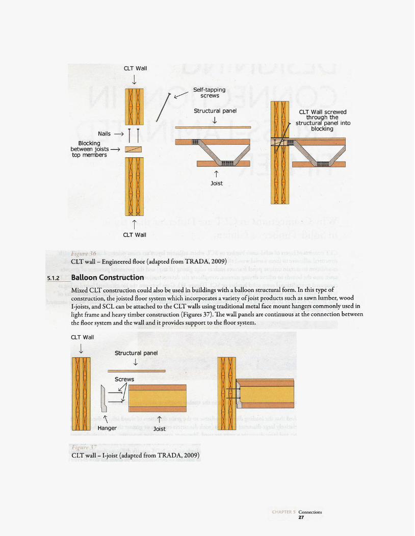
Figure 36 CLT wall - Engineered floor (adapted from TRADA, 2009) 27
Figure 37 CLT wall - I-joist (adapted from TRADA, 2009) 27
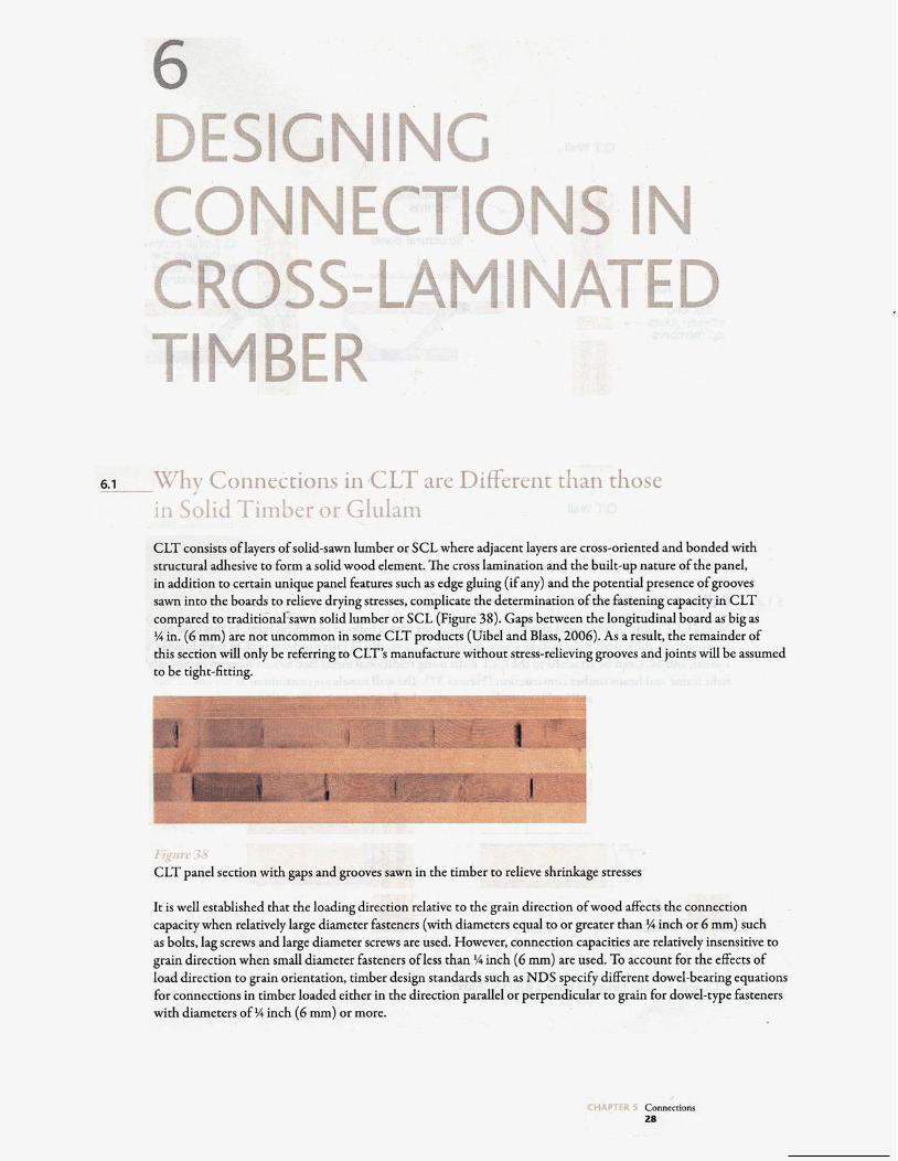
Figure 38 CLT panel section with gaps and grooves sawn in the timber to relieve shrinkage stresses 28
Figure39 Ductile failure modes typically experienced during testing ofself-tapping screws in CLT half-lapped connections 29
Figure 40 End and edge distances and spacings for dowel-type fasteners driven on edge (adapted from Draft CEN CLT standard, 2010) 32
Figure 41 Acoustic membrane inserted between walls and floors and underneath the metal bracket connector to provide air tightness (in exterior walls) and improve sound insulation 33
Figure 42 Tight fit between individual panels is ensured using special installation devices 34
Figure 43 Bolted lateral connection in CLT face lamination 36
Figure 44 Lateral resistance of half-lapped joint using lag screws 37
Figure 45 Withdrawal resistance of lag screws from CLT face lamination 39
Figure 46 Corner joint: lag screw lateral resistance in CLT edge 40
CHAPTER 5 Connections Vii
Figure 47 Corner Joint: lag screw withdrawal resistance in CLT edge 42
Figure 48 Nailed metal place connection to CLT (lateral and withdrawal) 43
CHAPTER 5 Connections viii
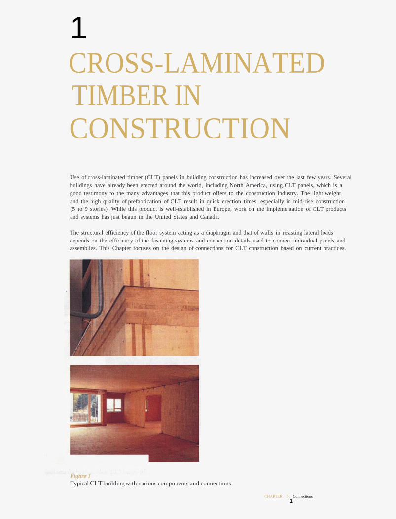
1 CROSS-LAMINATED TIMBER IN CONSTRUCTION Use of cross-laminated timber (CLT) panels in building construction has increased over the last few years. Several buildings have already been erected around the world, including North America, using CLT panels, which is a good testimony to the many advantages that this product offers to the construction industry. The light weight and the high quality of prefabrication of CLT result in quick erection times, especially in mid-rise construction (5 to 9 stories). While this product is well-established in Europe, work on the implementation of CLT products and systems has just begun in the United States and Canada.
The structural efficiency of the floor system acting as a diaphragm and that of walls in resisting lateral loads depends on the efficiency of the fastening systems and connection details used to connect individual panels and assemblies. This Chapter focuses on the design of connections for CLT construction based on current practices.
Figure 1 Typical CLT building with various components and connections
CHAPTER 5 Connections 1
COMMON STRUCTURAL SYSTEMS IN CLT There are several ways to design and construct CLT buildings. They all differ in the way the load-carrying panels/elements are arranged, the way the panels are connected together and by the type of wood and non-wood based materials used (such as the use of hybrid systems of construction). The most common forms of construction systems in CLT are:
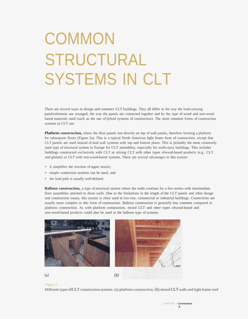
Platform construction, where the floor panels rest directly on top of wall panels, therefore forming a platform for subsequent floors (Figure 2a). This is a typical North American light frame form of construction, except that CLT panels are used instead of stud wall systems with top and bottom plates. This is probably the most commonly used type of structural system in Europe for CLT assemblies, especially for multi-story buildings. This includes buildings constructed exclusively with CLT or mixing CLT with other types ofwood-based products (e.g., CLT and glulam) or CLT with non-wood-based systems. There are several advantages to this system:
• it simplifies the erection of upper stories;
• simple connection systems can be used; and
• the load path is usually well-defined.
Balloon construction, a type of structural system where the walls continue for a few stories with intermediate floor assemblies attached to those walls. Due to the limitations in the length of the CLT panels and other design and construction issues, this system is often used in low-rise, commercial or industrial buildings. Connections are usually more complex in this form of construction. Balloon construction is generally less common compared to platform construction. As with platform construction, mixed CLT and other types ofwood-based and non-wood-based products could also be used in the balloon type of systems.
Figure 2 Different types ofCLT construction systems: (a) platform construction; (b) mixed CLT walls and light frame roof
CHAPTER 5 Connections 2
3 INTRODUCTION TO CONNECTIONS IN CLT ASSEMBLIES-OVERVIEW
3.1 General Connections in heavy timber construction, including those built with CLT, play an essential role in providing strength, stiffness, stability and ductility to the structure; consequently, they require careful attention by designers. Post-disaster surveys following strong earthquakes and hurricanes have shown that, among other reasons, structural failures often occur due to inadequately designed or improperly installed connections. The interruption of continuity in the timber structure caused by the presence of connections may result in a decrease in the overall strength and stiffness of the structure (i.e. if not properly designed or constructed) which in turn implies an increase in the cross-section of the assembled timber elements.
When structural members are attached with fasteners or some other types of metal hardware, such joints are referred to as “mechanicalconnections”.Typically, large fastener spacingas well as end and edge distances are required in most mechanical connections to avoid splitting and shear failures that are brittle in nature. The efficient design and fabrication of connections often determines the level of success of timber buildings when competing with other types ofstructural applications such as steel or concrete. This is particularly important for multi-story heavy timber structures and hybrid buildings, where CLT is used alone or could be used in combination with steel or concrete components.
The use of CLT panels enables a high degree of prefabrication at the plant. This is facilitated by the use of computer numerically controlled (CNC) machining technology to profile the panel for installation, at the plant, of conventional and sophisticated connection ststems with a high degree of accuracy and efficiency. The dimensional stability of CLT products due to the use of kiln-dried (KD) source material is better for connection ‘stability’ prior to installation and ensures good accuracy at installation.
In this section, a very brief overview of connection types is provided. More detailed information is provided in Section 4 of this Chapter.
3.2 Connection Systems Commonly used in CLT Assemblies Currently, there is a wide variety of fasteners and many different types of joint details that can be used to establish roof/wall, wall/floor, and inter-story connections in CLT assemblies or to connect CLT panels to other wood-based, concrete or steel elements in hybrid construction. While long self-tapping screws are typically recommended by CLT manufacturers and are commonly used for connectting panels to panels in floors and
CHAPTER 5 Connections 3
floor-to-wall assemblies, traditional dowel-type fasteners such as wood screws, nails, lag screws, bolts and dowels can also be effectively used in connecting panel elements together. Other types of traditional fasteners, including bearing type fasteners such as split rings and shear plates, and tooth plates, may have some potential; however, their use is expected to be limited to applications where high loads are involved. Some interesting innovative connection systems are finding their way to the CLT construction market. These include glued-in rods, the KNAPP® system and other systems that adopt similar concepts. Such systems have good potential for use in CLT applications, especially those that employ a high degree of prefabrication using CNC machining technology. Fortunately, major CLT panel and glulam manufacturing facilities are equipped with CNC technology which could facilitate the rapid adoption of such connection systems. The choice of the type of connection to use depends largely on the type of assemblies to be connected (i.e., panel-to-panel, floor to wall, etc.), panel configurations, and the type of structural system used in the building.
The following sections provide some basic information on the most commonly used types of mechanical fasteners in CLT assemblies. Detailed applications of these fasteners are presented in Section 4 of this Chapter.
3.2.1 Wood and Self-tapping Screws
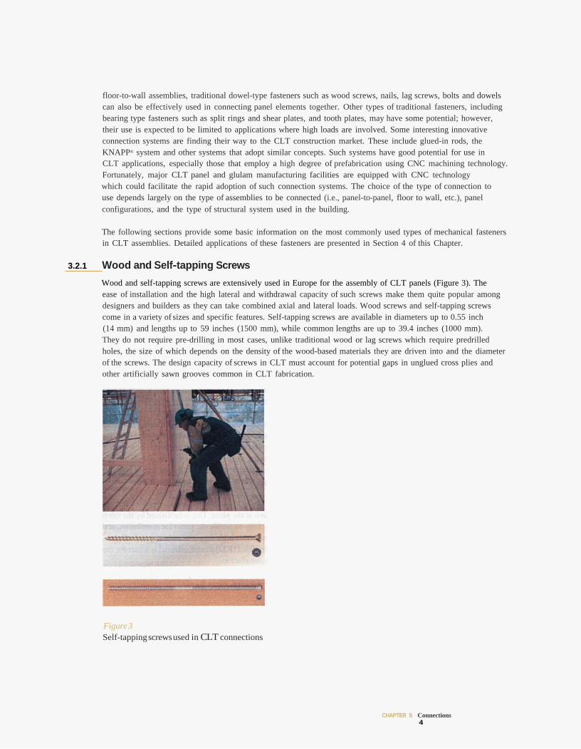
Wood and self-tapping screws are extensively used in Europe for the assembly of CLT panels (Figure 3). The ease of installation and the high lateral and withdrawal capacity of such screws make them quite popular among designers and builders as they can take combined axial and lateral loads. Wood screws and self-tapping screws come in a variety of sizes and specific features. Self-tapping screws are available in diameters up to 0.55 inch (14 mm) and lengths up to 59 inches (1500 mm), while common lengths are up to 39.4 inches (1000 mm). They do not require pre-drilling in most cases, unlike traditional wood or lag screws which require predrilled holes, the size of which depends on the density of the wood-based materials they are driven into and the diameter of the screws. The design capacity of screws in CLT must account for potential gaps in unglued cross plies and other artificially sawn grooves common in CLT fabrication.
Figure 3 Self-tapping screws used in CLT connections
CHAPTER 5 Connections 4
3.2.2 Nails
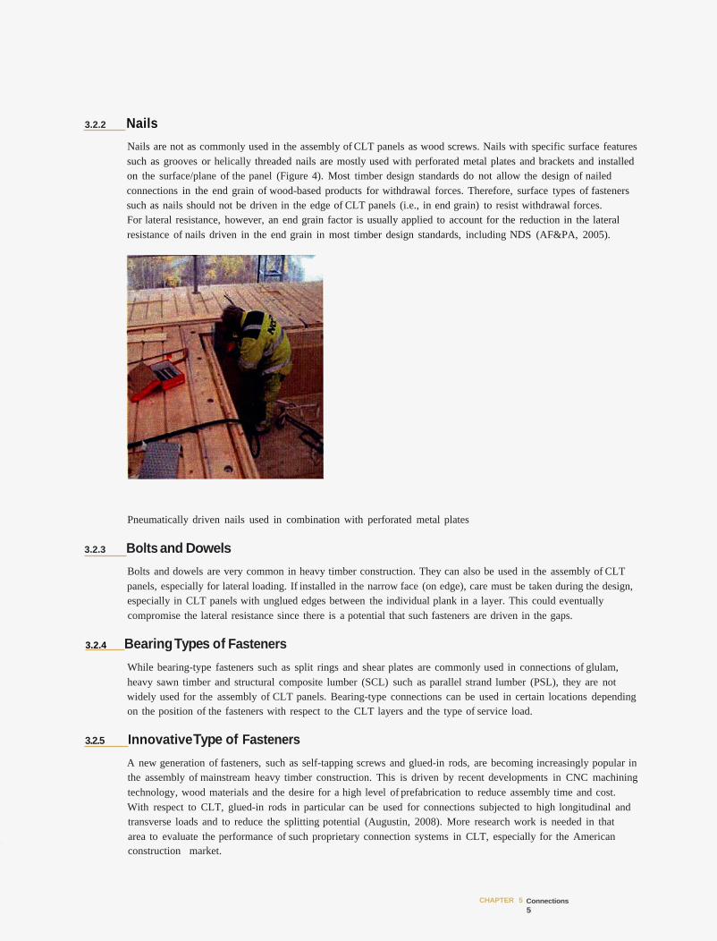
Nails are not as commonly used in the assembly of CLT panels as wood screws. Nails with specific surface features such as grooves or helically threaded nails are mostly used with perforated metal plates and brackets and installed on the surface/plane of the panel (Figure 4). Most timber design standards do not allow the design of nailed connections in the end grain of wood-based products for withdrawal forces. Therefore, surface types of fasteners such as nails should not be driven in the edge of CLT panels (i.e., in end grain) to resist withdrawal forces. For lateral resistance, however, an end grain factor is usually applied to account for the reduction in the lateral resistance of nails driven in the end grain in most timber design standards, including NDS (AF&PA, 2005).
Pneumatically driven nails used in combination with perforated metal plates
3.2.3 Bolts and Dowels
Bolts and dowels are very common in heavy timber construction. They can also be used in the assembly of CLT panels, especially for lateral loading. If installed in the narrow face (on edge), care must be taken during the design, especially in CLT panels with unglued edges between the individual plank in a layer. This could eventually compromise the lateral resistance since there is a potential that such fasteners are driven in the gaps.
3.2.4 Bearing Types of Fasteners
While bearing-type fasteners such as split rings and shear plates are commonly used in connections of glulam, heavy sawn timber and structural composite lumber (SCL) such as parallel strand lumber (PSL), they are not widely used for the assembly of CLT panels. Bearing-type connections can be used in certain locations depending on the position of the fasteners with respect to the CLT layers and the type of service load.
3.2.5 InnovativeType of Fasteners
A new generation of fasteners, such as self-tapping screws and glued-in rods, are becoming increasingly popular in the assembly of mainstream heavy timber construction. This is driven by recent developments in CNC machining technology, wood materials and the desire for a high level of prefabrication to reduce assembly time and cost. With respect to CLT, glued-in rods in particular can be used for connections subjected to high longitudinal and transverse loads and to reduce the splitting potential (Augustin, 2008). More research work is needed in that area to evaluate the performance of such proprietary connection systems in CLT, especially for the American construction market.
CHAPTER 5 Connections 5
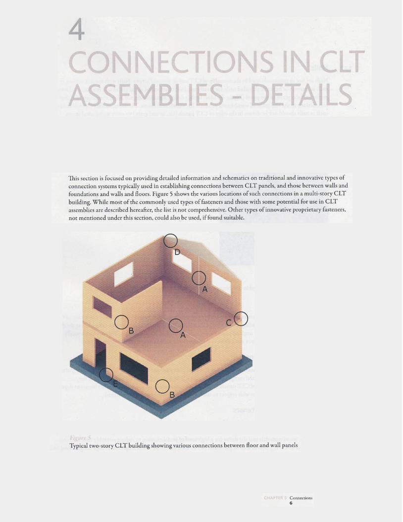
4.1 Panel-to-panel (Detail A) This is the fundamental form of connection that is typically used to form wall and floor assemblies. It is used to connect panels along their longitudinal edges. Due to production and transport limitations related to the size of the panel that can be delivered to building sites, panel-to-panel connections are established mostly on site. Connection details must be easy to assemble and should facilitate quick fabrication. The panel-to-panel connection facilitates the transfer of in- and out-of-plane forces through the wall or floor assembly. For example, when panel-to-panel connections are used in wall assembly, the connection must be designed to resist in-plane shear and out-of-plane bending. When the connection is used in floor assemblies acting as diaphragms, however, the connection must be capable of transferring in-plane diaphragm forces in principle, and maintain the integrity of the diaphragms and the overall, lateral load resisting system. Several possible panel-to-panel connection details are described below.
4.1.1 Internal Splines
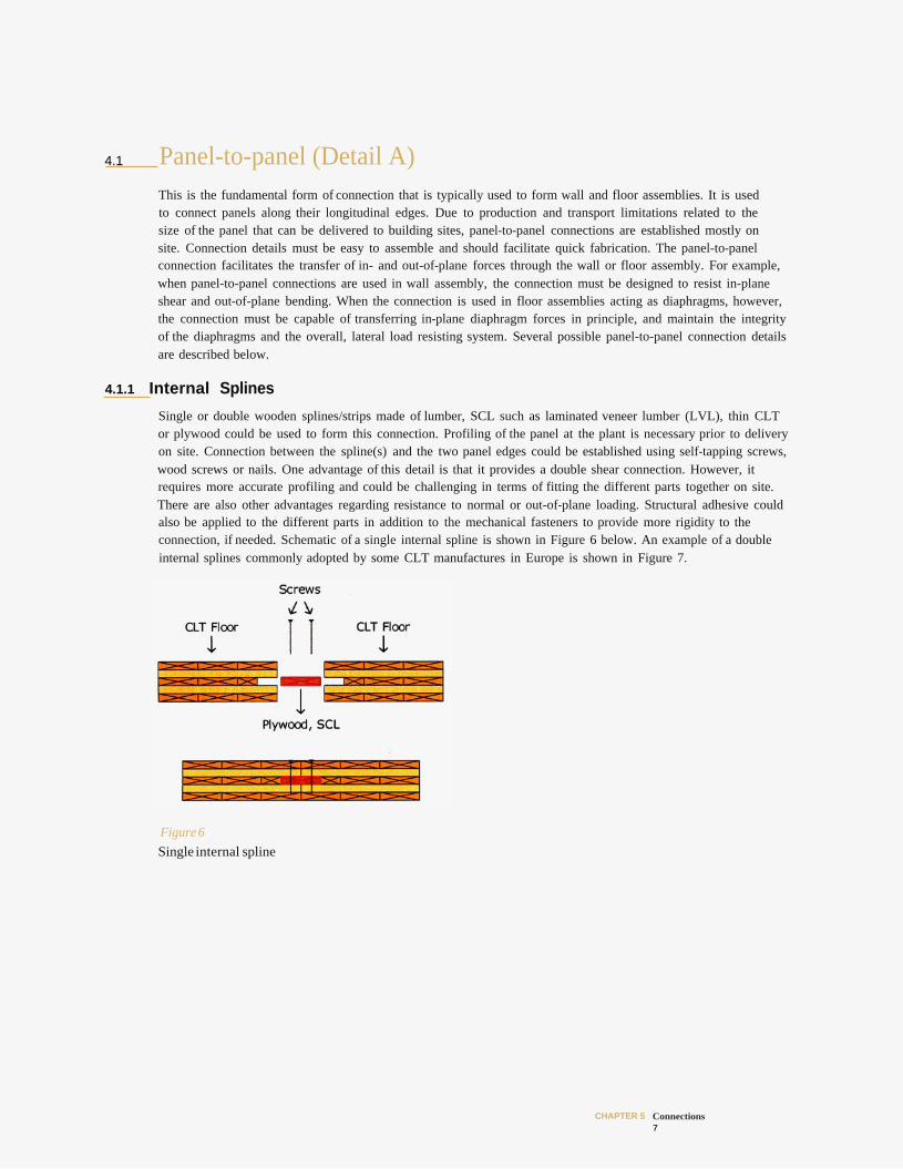
Single or double wooden splines/strips made of lumber, SCL such as laminated veneer lumber (LVL), thin CLT or plywood could be used to form this connection. Profiling of the panel at the plant is necessary prior to delivery on site. Connection between the spline(s) and the two panel edges could be established using self-tapping screws, wood screws or nails. One advantage of this detail is that it provides a double shear connection. However, it requires more accurate profiling and could be challenging in terms of fitting the different parts together on site. There are also other advantages regarding resistance to normal or out-of-plane loading. Structural adhesive could also be applied to the different parts in addition to the mechanical fasteners to provide more rigidity to the connection, if needed. Schematic of a single internal spline is shown in Figure 6 below. An example of a double internal splines commonly adopted by some CLT manufactures in Europe is shown in Figure 7.
Figure 6 Single internal spline
CHAPTER 5 Connections 7
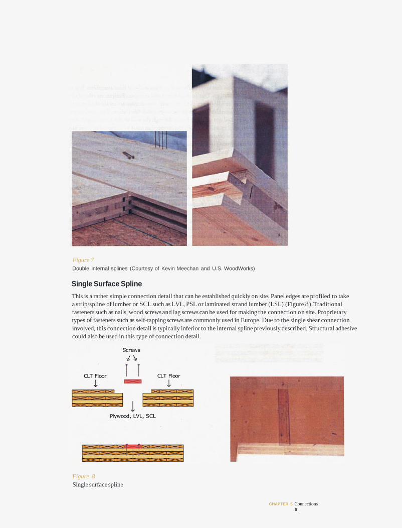
Figure 7 Double internal splines (Courtesy of Kevin Meechan and U.S. WoodWorks)
Single Surface Spline This is a rather simple connection detail that can be established quickly on site. Panel edges are profiled to take a strip/spline of lumber or SCL such as LVL, PSL or laminated strand lumber (LSL) (Figure 8).Traditional fasteners such as nails, wood screws and lag screws can be used for making the connection on site. Proprietary types of fasteners such as self-tapping screws are commonly used in Europe. Due to the single shear connection involved, this connection detail is typically inferior to the internal spline previously described. Structural adhesive could also be used in this type of connection detail.
Figure 8 Single surface spline
CHAPTER 5 Connections 8
4.1.3 Double Surface Splines
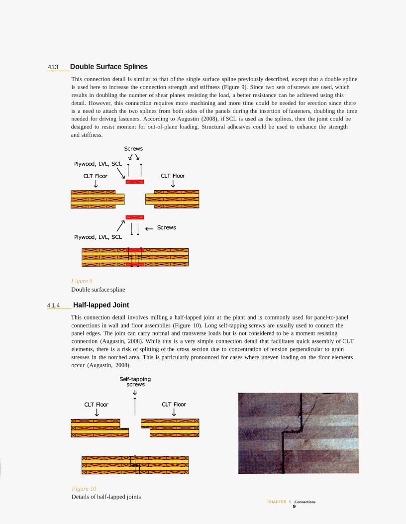
This connection detail is similar to that of the single surface spline previously described, except that a double spline is used here to increase the connection strength and stiffness (Figure 9). Since two sets of screws are used, which results in doubling the number of shear planes resisting the load, a better resistance can be achieved using this detail. However, this connection requires more machining and more time could be needed for erection since there is a need to attach the two splines from both sides of the panels during the insertion of fasteners, doubling the time needed for driving fasteners. According to Augustin (2008), if SCL is used as the splines, then the joint could be designed to resist moment for out-of-plane loading. Structural adhesives could be used to enhance the strength and stiffness.
Figure 9 Double surface spline
4.1.4 Half-lapped Joint
This connection detail involves milling a half-lapped joint at the plant and is commonly used for panel-to-panel connections in wall and floor assemblies (Figure 10). Long self-tapping screws are usually used to connect the panel edges. The joint can carry normal and transverse loads but is not considered to be a moment resisting connection (Augustin, 2008). While this is a very simple connection detail that facilitates quick assembly of CLT elements, there is a risk of splitting of the cross section due to concentration of tension perpendicular to grain stresses in the notched area. This is particularly pronounced for cases where uneven loading on the floor elements occur (Augustin, 2008).
Figure 10 Details of half-lapped joints
CHAPTER 5 Connections 9
4.1.5 Tube Connection System
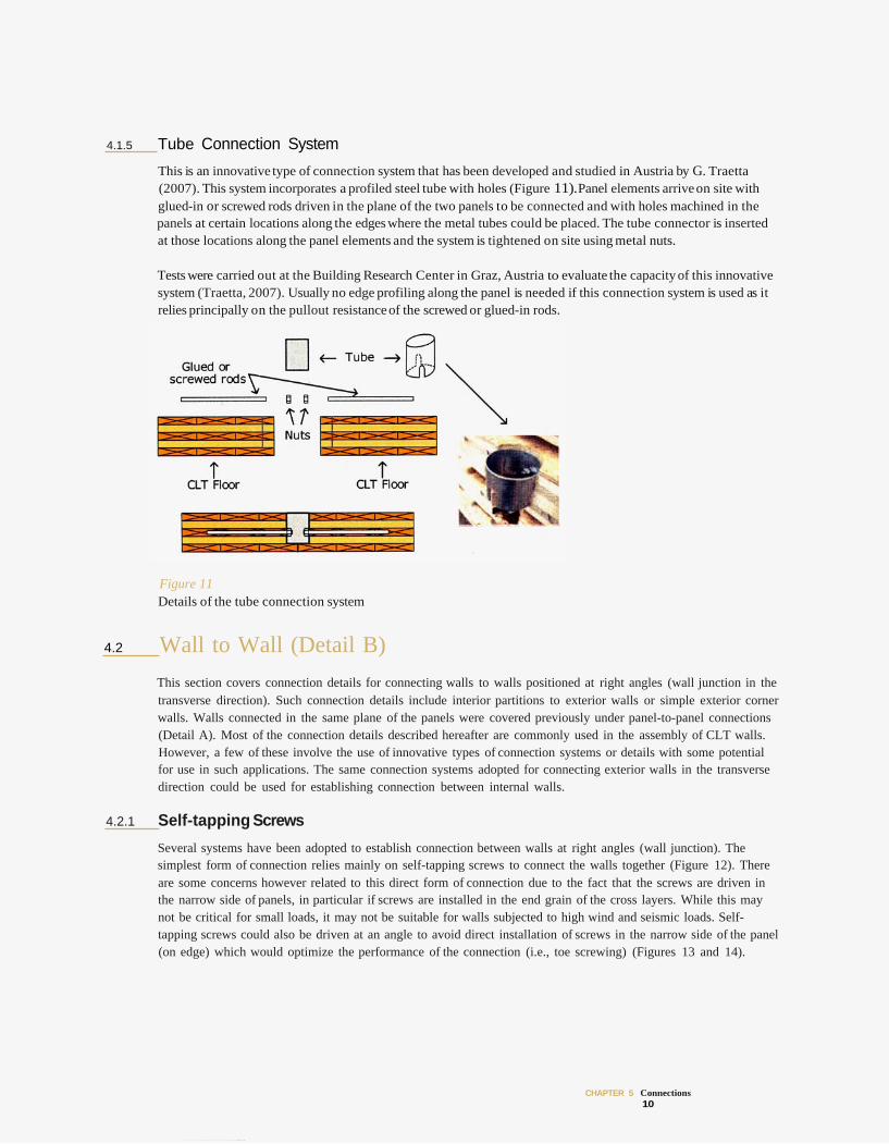
This is an innovative type of connection system that has been developed and studied in Austria by G. Traetta (2007). This system incorporates a profiled steel tube with holes (Figure 11).Panel elements arrive on site with glued-in or screwed rods driven in the plane of the two panels to be connected and with holes machined in the panels at certain locations along the edges where the metal tubes could be placed. The tube connector is inserted at those locations along the panel elements and the system is tightened on site using metal nuts.
Tests were carried out at the Building Research Center in Graz, Austria to evaluate the capacity of this innovative system (Traetta, 2007). Usually no edge profiling along the panel is needed if this connection system is used as it relies principally on the pullout resistance of the screwed or glued-in rods.
Figure 11 Details of the tube connection system
4.2 Wall to Wall (Detail B) This section covers connection details for connecting walls to walls positioned at right angles (wall junction in the transverse direction). Such connection details include interior partitions to exterior walls or simple exterior corner walls. Walls connected in the same plane of the panels were covered previously under panel-to-panel connections (Detail A). Most of the connection details described hereafter are commonly used in the assembly of CLT walls. However, a few of these involve the use of innovative types of connection systems or details with some potential for use in such applications. The same connection systems adopted for connecting exterior walls in the transverse direction could be used for establishing connection between internal walls.
4.2.1 Self-tapping Screws
Several systems have been adopted to establish connection between walls at right angles (wall junction). The simplest form of connection relies mainly on self-tapping screws to connect the walls together (Figure 12). There are some concerns however related to this direct form of connection due to the fact that the screws are driven in the narrow side of panels, in particular if screws are installed in the end grain of the cross layers. While this may not be critical for small loads, it may not be suitable for walls subjected to high wind and seismic loads. Self-tapping screws could also be driven at an angle to avoid direct installation of screws in the narrow side of the panel (on edge) which would optimize the performance of the connection (i.e., toe screwing) (Figures 13 and 14).
CHAPTER 5 Connections 10
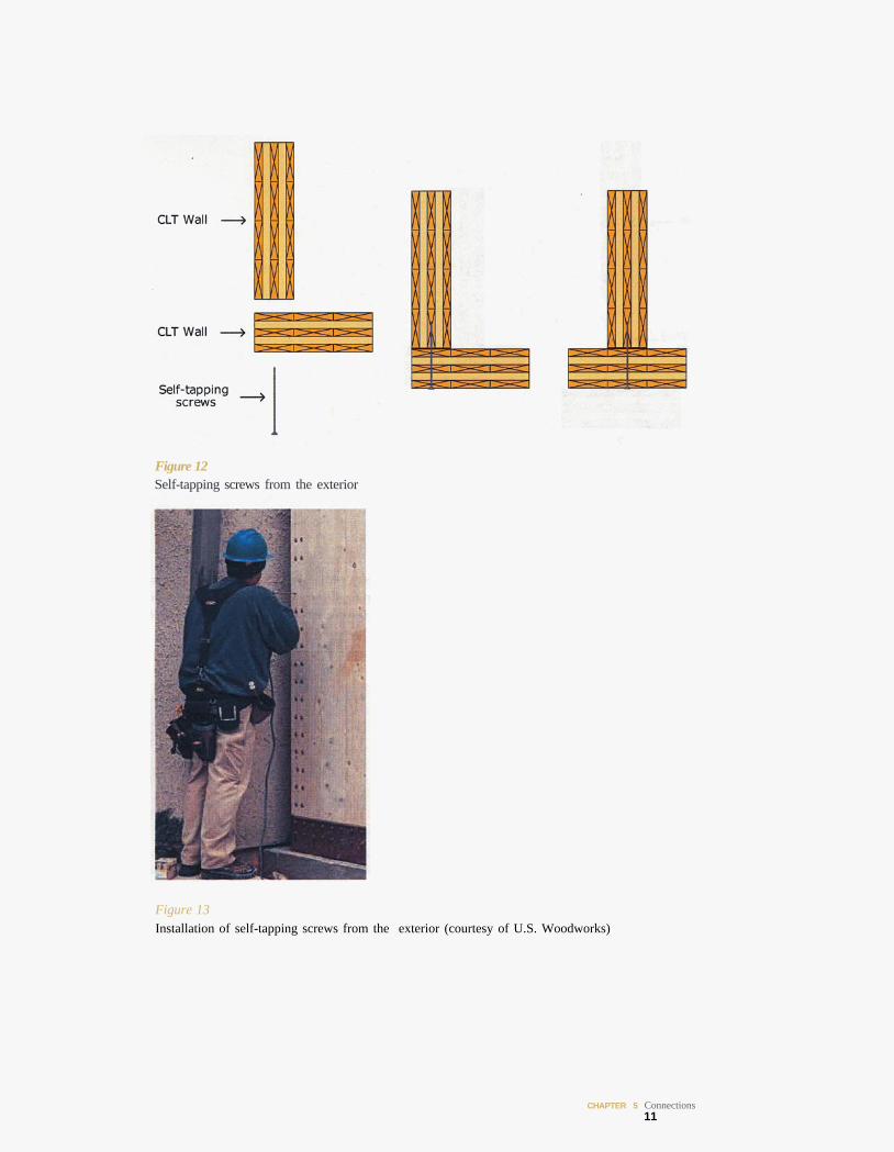
Figure 12 Self-tapping screws from the exterior
Figure 13 Installation of self-tapping screws from the exterior (courtesy of U.S. Woodworks)
CHAPTER 5 Connections 11
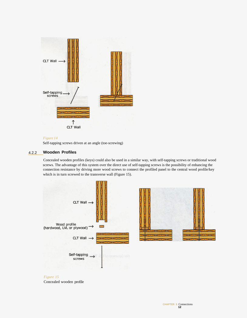
Figure 14 Self-tapping screws driven at an angle (toe-screwing)
4.2.2 Wooden Profiles
Concealed wooden profiles (keys) could also be used in a similar way, with self-tapping screws or traditional wood screws. The advantage of this system over the direct use of self-tapping screws is the possibility of enhancing the connection resistance by driving more wood screws to connect the profiled panel to the central wood profile/key which is in turn screwed to the transverse wall (Figure 15).
Figure 15 Concealed wooden profile
CHAPTER 5 Connections 12
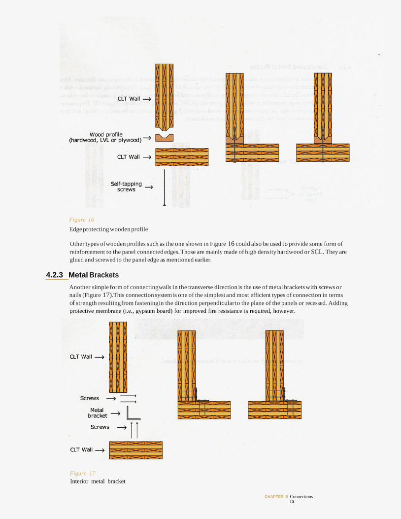
Figure 16 Edge protecting wooden profile
Other types ofwooden profiles such as the one shown in Figure 16 could also be used to provide some form of reinforcement to the panel connected edges. Those are mainly made of high density hardwood or SCL. They are glued and screwed to the panel edge as mentioned earlier.
4.2.3 Metal Brackets Another simple form of connectingwalls in the transverse direction is the use of metal brackets with screws or nails (Figure 17).This connection system is one of the simplest and most efficient types of connection in terms of strength resultingfrom fasteningin the direction perpendicularto the plane of the panels or recessed. Adding protective membrane (i.e., gypsum board) for improved fire resistance is required, however.
Figure 17 Interior metal bracket
CHAPTER 5 Connections 13
4.2.4 Concealed Metal Plates
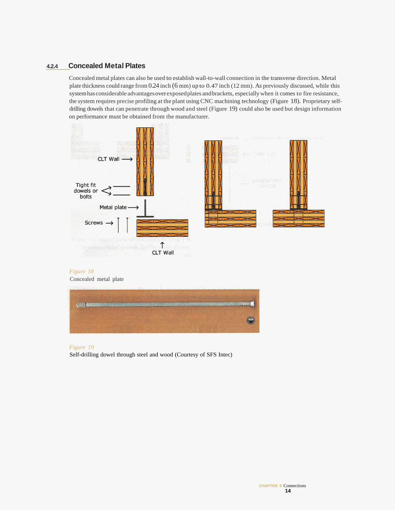
Concealed metal plates can also be used to establish wall-to-wall connection in the transverse direction. Metal plate thickness could range from 0.24 inch (6 mm) up to 0.47 inch (12 mm). As previously discussed, while this system has considerable advantages over exposed plates and brackets, especially when it comes to fire resistance, the system requires precise profiling at the plant using CNC machining technology (Figure 18). Proprietary self-drilling dowels that can penetrate through wood and steel (Figure 19) could also be used but design information on performance must be obtained from the manufacturer.
Figure 18 Concealed metal plate
Figure 19 Self-drilling dowel through steel and wood (Courtesy of SFS Intec)
CHAPTER 5 Connections 14
4.3 Wall to Floor (Detail C) Several possibilities exist when it comes to connecting walls to the floors above or connecting walls on the upper stories to floors, depending on the form of structural systems (i.e., platform vs. balloon), availability of fasteners and the degree of prefabrication. When platform construction is used, cumulative effects of bearing deformations should be addressed in the connection design.
4.3.1 Platform Construciton
4.3.1.1 Self-tapping Screws
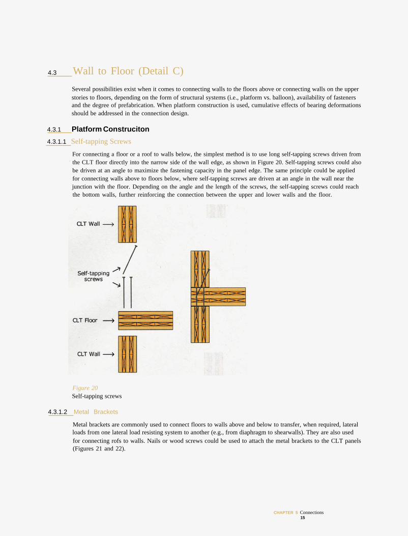
For connecting a floor or a roof to walls below, the simplest method is to use long self-tapping screws driven from the CLT floor directly into the narrow side of the wall edge, as shown in Figure 20. Self-tapping screws could also be driven at an angle to maximize the fastening capacity in the panel edge. The same principle could be applied for connecting walls above to floors below, where self-tapping screws are driven at an angle in the wall near the junction with the floor. Depending on the angle and the length of the screws, the self-tapping screws could reach the bottom walls, further reinforcing the connection between the upper and lower walls and the floor.
Figure 20 Self-tapping screws
4.3.1.2 Metal Brackets
Metal brackets are commonly used to connect floors to walls above and below to transfer, when required, lateral loads from one lateral load resisting system to another (e.g., from diaphragm to shearwalls). They are also used for connecting rofs to walls. Nails or wood screws could be used to attach the metal brackets to the CLT panels (Figures 21 and 22).
CHAPTER 5 Connections 15
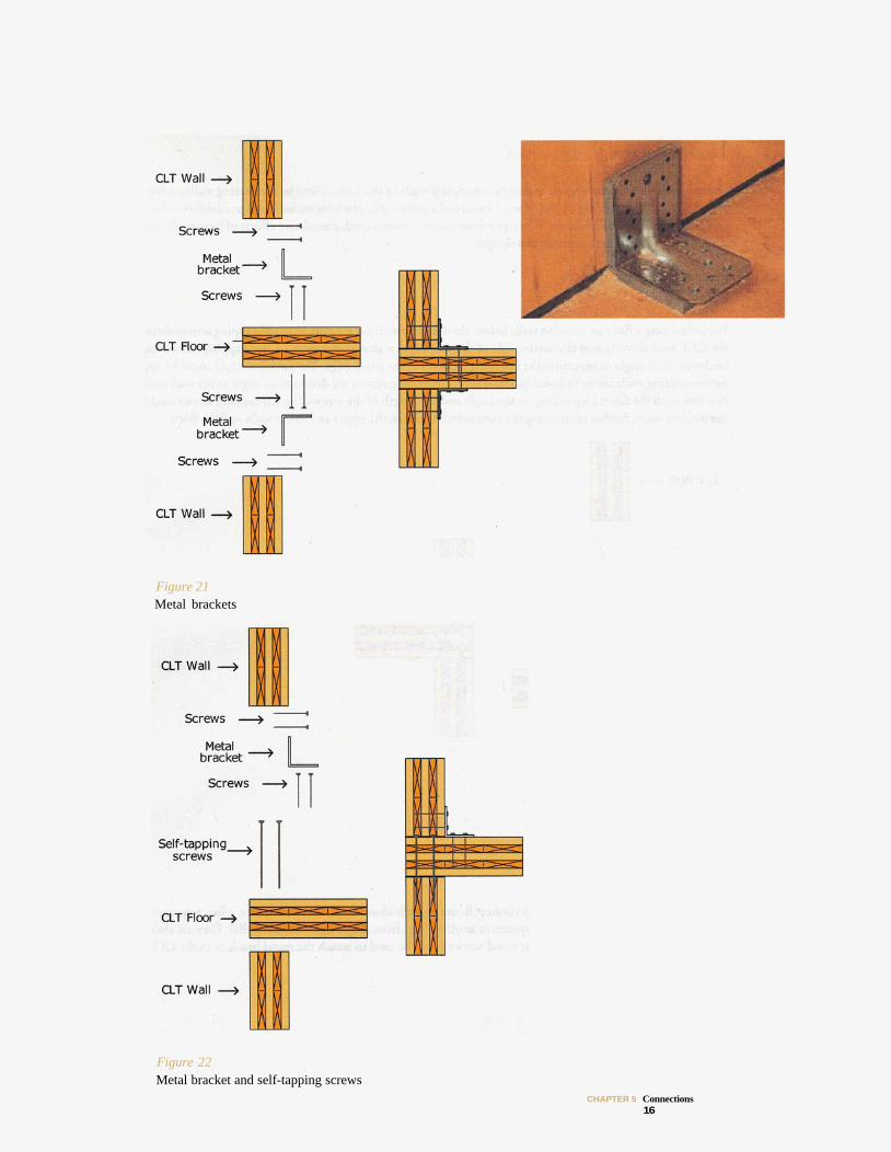
Figure 21 Metal brackets
Figure 22 Metal bracket and self-tapping screws
CHAPTER 5 Connections 16
4.3.1.3 Concealed Metal Plates
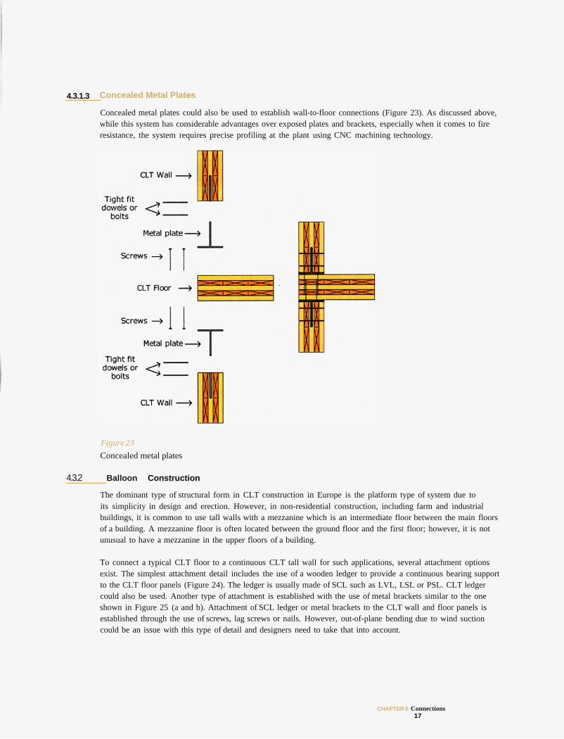
Concealed metal plates could also be used to establish wall-to-floor connections (Figure 23). As discussed above, while this system has considerable advantages over exposed plates and brackets, especially when it comes to fire resistance, the system requires precise profiling at the plant using CNC machining technology.
Figure 23 Concealed metal plates
4.3.2 Balloon Construction
The dominant type of structural form in CLT construction in Europe is the platform type of system due to its simplicity in design and erection. However, in non-residential construction, including farm and industrial buildings, it is common to use tall walls with a mezzanine which is an intermediate floor between the main floors of a building. A mezzanine floor is often located between the ground floor and the first floor; however, it is not unusual to have a mezzanine in the upper floors of a building.
To connect a typical CLT floor to a continuous CLT tall wall for such applications, several attachment options exist. The simplest attachment detail includes the use of a wooden ledger to provide a continuous bearing support to the CLT floor panels (Figure 24). The ledger is usually made of SCL such as LVL, LSL or PSL. CLT ledger could also be used. Another type of attachment is established with the use of metal brackets similar to the one shown in Figure 25 (a and b). Attachment of SCL ledger or metal brackets to the CLT wall and floor panels is established through the use of screws, lag screws or nails. However, out-of-plane bending due to wind suction could be an issue with this type of detail and designers need to take that into account.
CHAPTER 5 Connections 17
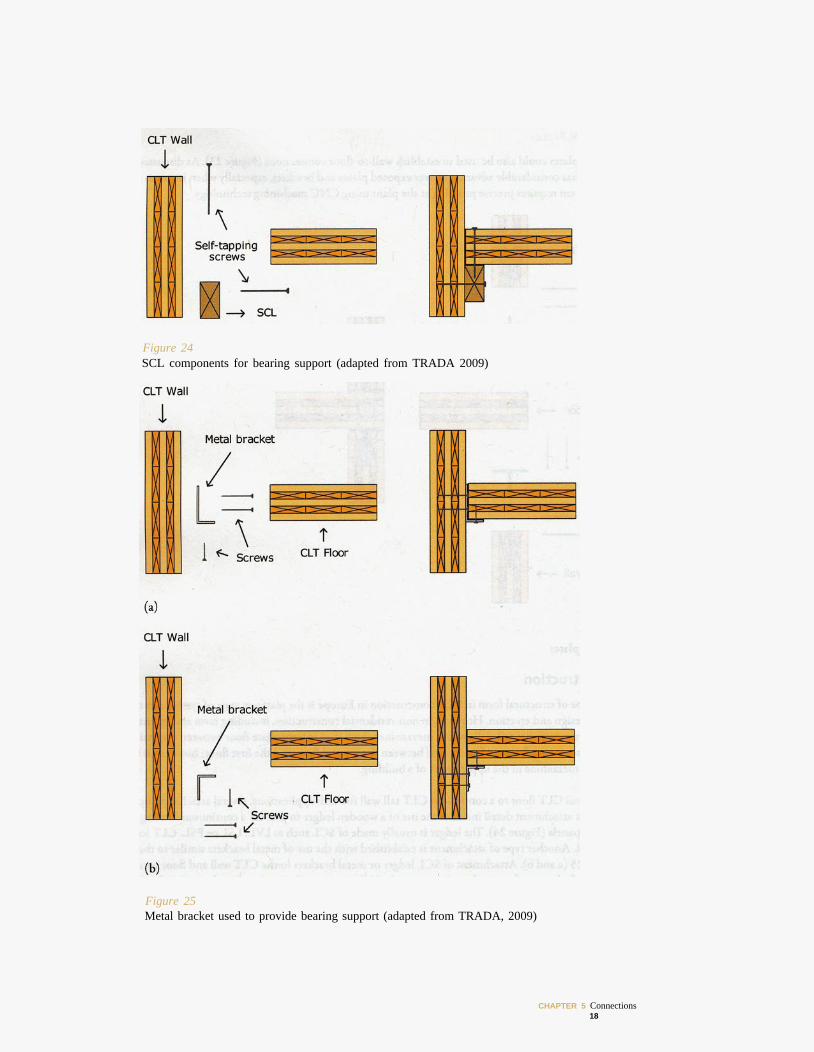
Figure 24 SCL components for bearing support (adapted from TRADA 2009)
Figure 25 Metal bracket used to provide bearing support (adapted from TRADA, 2009)
CHAPTER 5 Connections 18
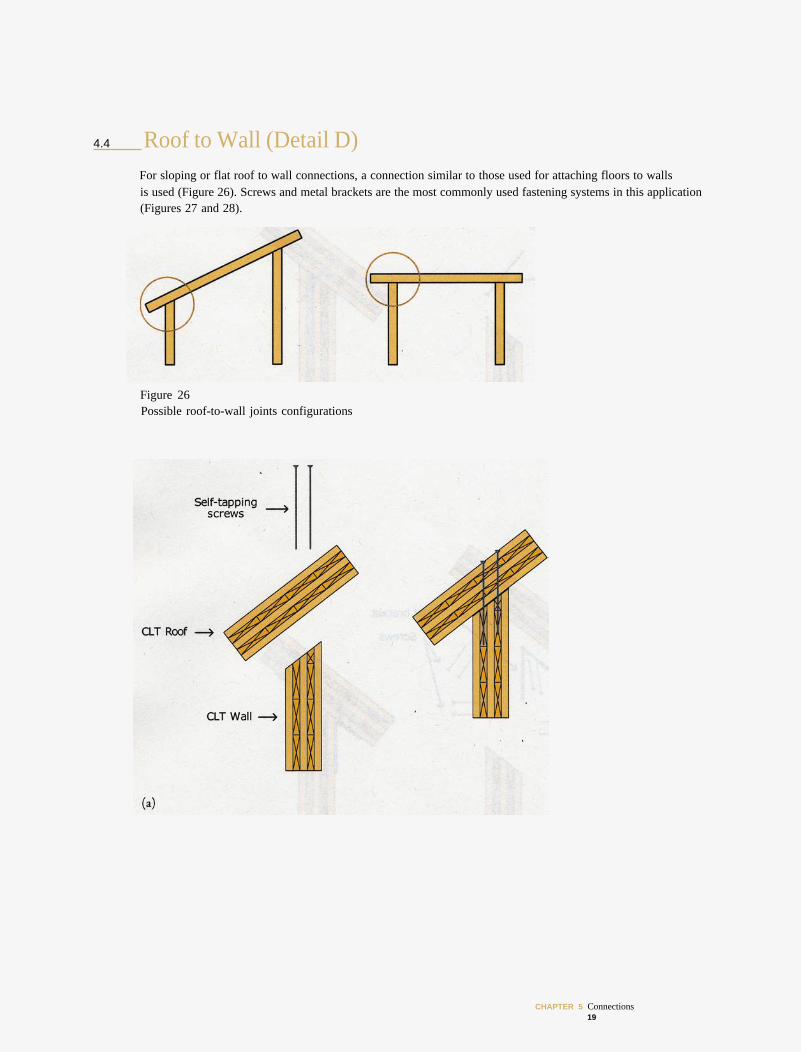
4.4 Roof to Wall (Detail D) For sloping or flat roof to wall connections, a connection similar to those used for attaching floors to walls is used (Figure 26). Screws and metal brackets are the most commonly used fastening systems in this application (Figures 27 and 28).
Figure 26 Possible roof-to-wall joints configurations
CHAPTER 5 Connections 19
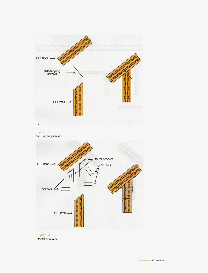
Figure 27 Self-tapping screws
Figure 28 Metal brackets
CHAPTER 5 Connections
4.5 Wall to Foundations (Detail E) 4.5.1"________I Visible/Exposed Plates
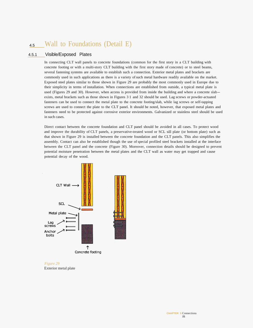
In connecting CLT wall panels to concrete foundations (common for the first story in a CLT building with concrete footing or with a multi-story CLT building with the first story made of concrete) or to steel beams, several fastening systems are available to establish such a connection. Exterior metal plates and brackets are commonly used in such applications as there is a variety of such metal hardware readily available on the market. Exposed steel plates similar to those shown in Figure 29 are probably the most commonly used in Europe due to their simplicity in terms of installation. When connections are established from outside, a typical metal plate is used (Figures 29 and 30). However, when access is provided from inside the building and where a concrete slab-exists, metal brackets such as those shown in Figures 3 1 and 32 should be used. Lag screws or powder-actuated fasteners can be used to connect the metal plate to the concrete footing/slab, while lag screws or self-tapping screws are used to connect the plate to the CLT panel. It should be noted, however, that exposed metal plates and fasteners need to be protected against corrosive exterior environments. Galvanized or stainless steel should be used in such cases.
Direct contact between the concrete foundation and CLT panel should be avoided in all cases. To protect wood and improve the durability of CLT panels, a preservative-treated wood or SCL sill plate (or bottom plate) such as that shown in Figure 29 is installed between the concrete foundation and the CLT panels. This also simplifies the assembly. Contact can also be established though the use of special profiled steel brackets installed at the interface between the CLT panel and the concrete (Figure 30). Moreover, connection details should be designed to prevent potential moisture penetration between the metal plates and the CLT wall as water may get trapped and cause potential decay of the wood.
Figure 29 Exterior metal plate
CHAPTER 5 Connections 21
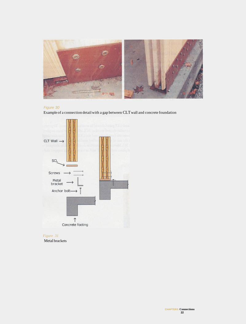
Figure 30 Example of a connection detail with a gap between CLT wall and concrete foundation
Figure 31 Metal brackets
CHAPTER 5 Connections 22
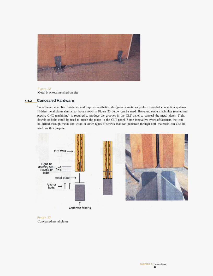
Figure 32 Metal brackets installed on site
4.5.2 Concealed Hardware
To achieve better fire resistance and improve aesthetics, designers sometimes prefer concealed connection systems. Hidden metal plates similar to those shown in Figure 33 below can be used. However, some machining (sometimes precise CNC machining) is required to produce the grooves in the CLT panel to conceal the metal plates. Tight dowels or bolts could be used to attach the plates to the CLT panel. Some innovative types of fasteners that can be drilled through metal and wood or other types of screws that can penetrate through both materials can also be used for this purpose.
Figure 33 Concealed metal plates
CHAPTER 5 Connections 23
4.5.3 Wooden Profiles
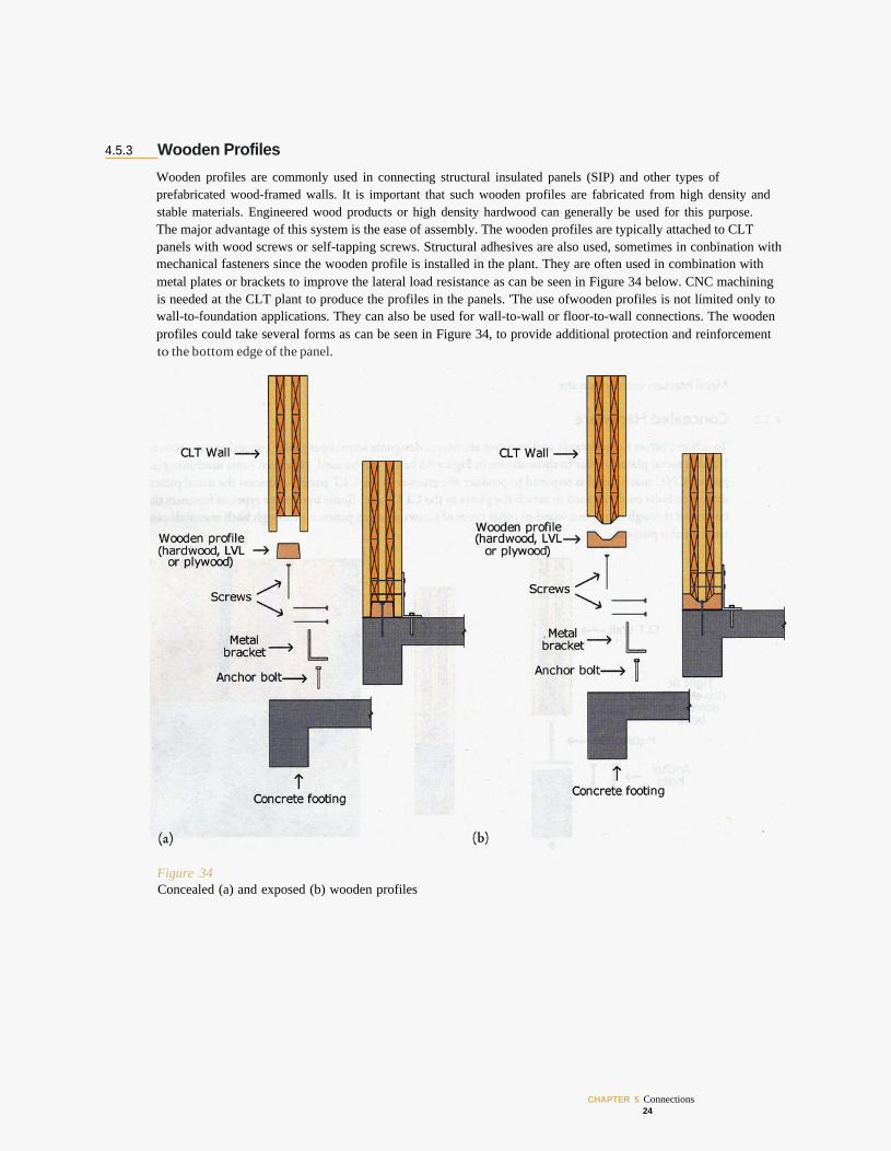
Wooden profiles are commonly used in connecting structural insulated panels (SIP) and other types of prefabricated wood-framed walls. It is important that such wooden profiles are fabricated from high density and stable materials. Engineered wood products or high density hardwood can generally be used for this purpose. The major advantage of this system is the ease of assembly. The wooden profiles are typically attached to CLT panels with wood screws or self-tapping screws. Structural adhesives are also used, sometimes in conbination with mechanical fasteners since the wooden profile is installed in the plant. They are often used in combination with metal plates or brackets to improve the lateral load resistance as can be seen in Figure 34 below. CNC machining is needed at the CLT plant to produce the profiles in the panels. 'The use ofwooden profiles is not limited only to wall-to-foundation applications. They can also be used for wall-to-wall or floor-to-wall connections. The wooden profiles could take several forms as can be seen in Figure 34, to provide additional protection and reinforcement to the bottom edge of the panel.
Figure 34 Concealed (a) and exposed (b) wooden profiles
CHAPTER 5 Connections 24
5 CONNECTIONS IN MIXED HYBRID CLT CONSTRUCTION– DETAILS Mixed systems using CLT with other types ofwood-based materials such as glued-laminated timber (glulam) are common. Mixed systems are becoming increasingly popular in Europe as a way to optimize the overall design by capitalizing on the positive attributes of the various products. Mixing CLT with other types of construction materials such as concrete and masonry or mixing different types of structural forms is also common.
5.1 Mixed CLT with Other Wood-based Materials and Systems In CLT assemblies, mixing different wood-based materials and different structural systems is done in such a way to optimize the design and to meet certain performance requirements. Therefore, it is not unusual to combine CLT wall assemblies with floor joist systems using glulam, wood I-joists, metal plated wood trusses or other types of engineered wood elements as the main floor support system, with either wood-based decking such as wood boards or wood structural panels. The following provides a brief summary of potential structural forms where CLT and other types of wood-based materials could be combined. Connection systems between those different materials are described.
5.1.1 Platform Construction For platform-type construction, the main structural supporting elements of the floor system rest on top of the walls below. In mixed construction where walls are made of CLT panels, typical joisted floor system is placed on top of those walls as can be seen in Figures 35 and 36.
CHAPTER 5 Connections 25
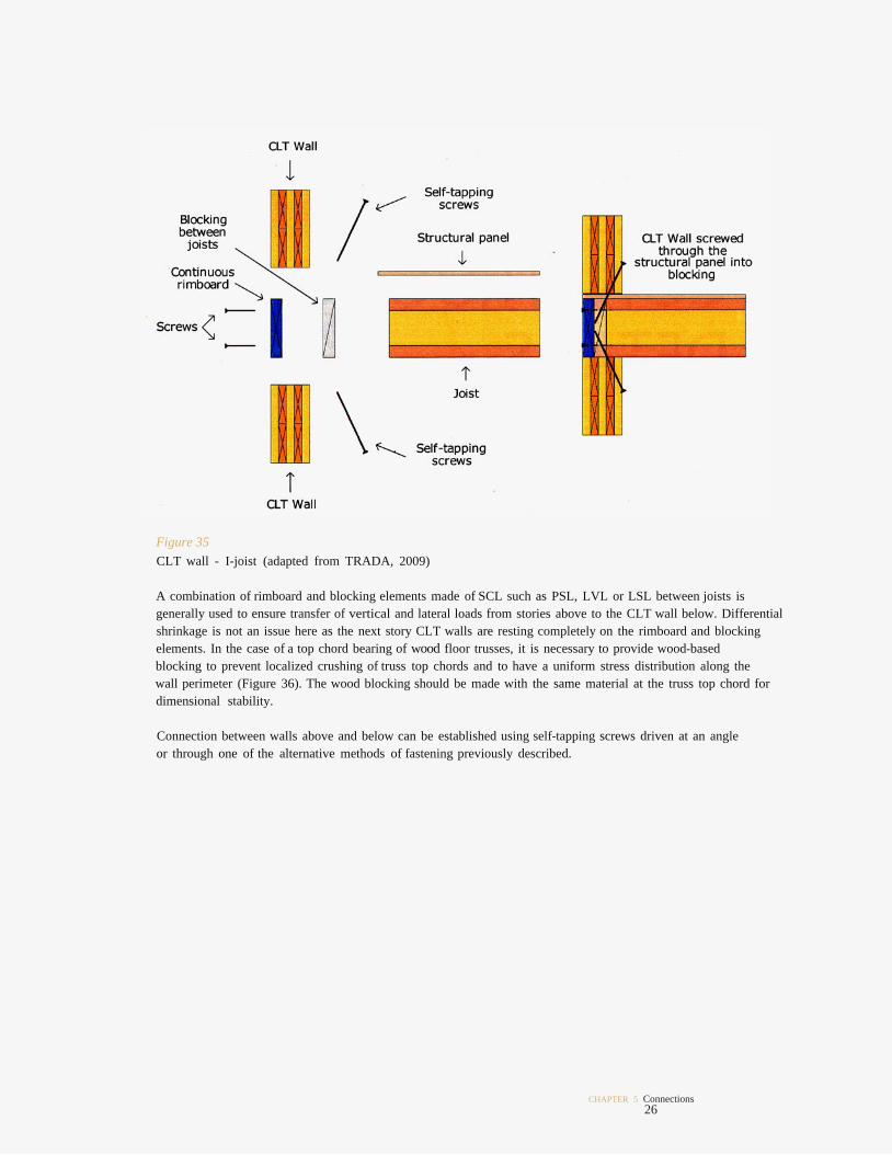
Figure 35 CLT wall - I-joist (adapted from TRADA, 2009)
A combination of rimboard and blocking elements made of SCL such as PSL, LVL or LSL between joists is generally used to ensure transfer of vertical and lateral loads from stories above to the CLT wall below. Differential shrinkage is not an issue here as the next story CLT walls are resting completely on the rimboard and blocking elements. In the case of a top chord bearing of wood floor trusses, it is necessary to provide wood-based blocking to prevent localized crushing of truss top chords and to have a uniform stress distribution along the wall perimeter (Figure 36). The wood blocking should be made with the same material at the truss top chord for dimensional stability.
Connection between walls above and below can be established using self-tapping screws driven at an angle or through one of the alternative methods of fastening previously described.
CHAPTER 5 Connections 26
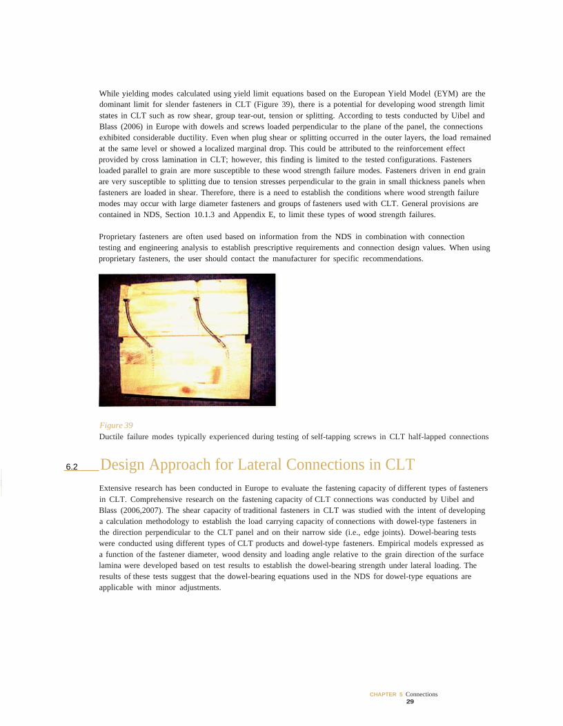
While yielding modes calculated using yield limit equations based on the European Yield Model (EYM) are the dominant limit for slender fasteners in CLT (Figure 39), there is a potential for developing wood strength limit states in CLT such as row shear, group tear-out, tension or splitting. According to tests conducted by Uibel and Blass (2006) in Europe with dowels and screws loaded perpendicular to the plane of the panel, the connections exhibited considerable ductility. Even when plug shear or splitting occurred in the outer layers, the load remained at the same level or showed a localized marginal drop. This could be attributed to the reinforcement effect provided by cross lamination in CLT; however, this finding is limited to the tested configurations. Fasteners loaded parallel to grain are more susceptible to these wood strength failure modes. Fasteners driven in end grain are very susceptible to splitting due to tension stresses perpendicular to the grain in small thickness panels when fasteners are loaded in shear. Therefore, there is a need to establish the conditions where wood strength failure modes may occur with large diameter fasteners and groups of fasteners used with CLT. General provisions are contained in NDS, Section 10.1.3 and Appendix E, to limit these types of wood strength failures.
Proprietary fasteners are often used based on information from the NDS in combination with connection testing and engineering analysis to establish prescriptive requirements and connection design values. When using proprietary fasteners, the user should contact the manufacturer for specific recommendations.
Figure 39 Ductile failure modes typically experienced during testing of self-tapping screws in CLT half-lapped connections
6.2 Design Approach for Lateral Connections in CLT Extensive research has been conducted in Europe to evaluate the fastening capacity of different types of fasteners in CLT. Comprehensive research on the fastening capacity of CLT connections was conducted by Uibel and Blass (2006,2007). The shear capacity of traditional fasteners in CLT was studied with the intent of developing a calculation methodology to establish the load carrying capacity of connections with dowel-type fasteners in the direction perpendicular to the CLT panel and on their narrow side (i.e., edge joints). Dowel-bearing tests were conducted using different types of CLT products and dowel-type fasteners. Empirical models expressed as a function of the fastener diameter, wood density and loading angle relative to the grain direction of the surface lamina were developed based on test results to establish the dowel-bearing strength under lateral loading. The results of these tests suggest that the dowel-bearing equations used in the NDS for dowel-type equations are applicable with minor adjustments.
CHAPTER 5 Connections 29
6.2.1 Fasteners Driven Perpendicularto the Plane of the Panel
For dowel-type fasteners where the dowel diameter is equal to or larger than 1/4 inch (6 mm), the dowel-bearing strengths, Fe, to use with the provisions of NDS 11.3 to calculate reference lateral design values for the two primary loading directions are:
Parallel to grain for the CLT ply at the shear plane:
[1]
Perpendicular to grain for the CLT ply at the shear plane:
[2]
Where:
= dowel-bearing strength parallel to grain (psi) for fastener where D 1/4 inch
= dowel-bearing strength perpendicular to grain (psi) for fastener where D 1/4 inch
G = minimum specific gravity of species used in CLT lay-ups
D = diameter (inches) of fastener penetration
Crossing layers will have different dowel-bearing strengths than the CLT ply at the shear plane. In most connections, the impact of this difference will be minimal; however, for connections using larger diameter fasteners or shorter dowel-bearing lengths, ls or lm, that is the “effective” length of the bearing length due to these layers should be reduced. For connections where the primary loading direction is parallel to grain for the CLT ply at the shear plane, the dowel bearing length should be reduced by multiplying the bearing length in the direction is perpendicular to grain for the CLT ply at the shear plane, the dowel-bearing length can conservatively
crossing plies (perpendicular to grain) by the ratio of For connections where the primary loading
remain unadjusted or be adjusted by increasing the bearing length in the crossing plies (parallel to grain) by the
design values based on parallel and perpendicular to grain design values should be used with these adjusted ratio of For connections loaded at an angle to grain, the procedures in-NDS, Appendix J, for developing
“effective” lengths.
For dowel-type fasteners where the dowel diameter is less than 1/4 inch (6 mm), the dowel-bearing strength, Fe, to use with the provisions of NDS 11.3 to calculate reference lateral design values loading at any angle to the grain is:
[3]
Where:
Fe = dowel-bearing strength (psi) for fastener where D < 1/4 inch.
6.2.2“_l-ll___- Dowel-type Fasteners Driven in the Narrow Side of the CLT Panel
For dowel-type fasteners installed in the narrow edge of CLT panels, the effects of inter-ply edge distance and end grain effects can be dramatic. For the purpose of developing design values for fasteners installed in this orientation, the dowel-bearing strength for fasteners with dowel diameters equal to or larger than 1/4 inch (6 mm) should be limited to 0.55 times from Equation (2), regardless ofthe actual grain orientation of the penetrated member. For fasteners with dowel diameters ofless than 1/4 inch (6 mm), the use of 0.67 times Fe from Equation (3) is adequate.
CHAPTER 5 Connections 30
CLT connections using split rings and shear plates should be designed using principles and limitations of NDS Chapter 12. However, end distance, edge distance, and spacing limits are based on the use of split rings and shear plates installed in solid-sawn or glued-laminated lumber. For CLT, additional wood strength requirements should be checked to prevent unanticipated wood failures such as net section area tension, row tear-out and group tear-out addressed in NDS Appendix E.
CLT connections using timber rivets are beyond the application limits in the NDS and are not recommended at this time. Specific wood strength provisions must be developed for this application.
When using proprietary fasteners, the designer should contact the manufacturer for specific recommendations.
6.3 Design Approach for Withdrawal Connections in CLT Withdrawal strength of large diameter self-tapping screws installed perpendicular to the plane of CLT panels or in CLT panel edges was also investigated by Uibel and Blass (2007). The withdrawal resistance was derived from tests using self-tapping screws with diameters ranging from 1/4 inch (6 mm) to 1/2 inch (12 mm). The location of the screws was selected in such a way to have them installed at the joint between two boards within a lamina, or between one lamina and another (in the glue line). Comparative analysis studies using those proposed equations versus those given in the NDS suggest that the withdrawal equations provided in the NDS 11.2 for lag screws, wood screws, nails and spikes are also applicable to CLT installed perpendicular to the plane of the CLT and are as follows:
Lag screws:
[4]
Wood screws:
[5]
Smooth-shank nails and spikes:
[6]
Post-frame ring shank nails:
[7]
Where:
W = reference withdrawal design value (lb.) per inch of thread penetration as permitted in NDS
G = minimum specific gravity of species used in CLT lay-ups
D = diameter (inches) of fastener penetration
For the purpose of developing design values for fasteners installed in the narrow edge of CLT panels, the withdrawal equations and provisions in the NDS for fasteners installed in end grain should be followed. As a result, lag screw withdrawal values should be multiplied by the end grain factor (Ceg) of 0.75, as per NDS 11.5.2.1. Wood screws, nails, and spikes should not be loaded in withdrawal from end grain. When using proprietary fasteners, the designer should contact the manufacturer for specific recommendations.
CHAPTER 5 Connections 31
6.4 Placement of Fasteners in Joints Minimum requirements are given in the NDS for loaded end and edge distances, fastener spacing in a row and spacing between rows of fasteners for a variety of traditional fasteners with diameters equal to or greater than 1/4 inch (6 mm) such as bolts, lag screws, and dowels. Recommendations for smaller fasteners such as nails, spikes, and wood screws are not explicitly provided in the NDS, which only details a requirement to avoid splitting. However, some guidance is provided in the NDS Commentary for these types of fasteners. These requirements can be applied conservatively to fasteners driven or placed in the direction perpendicular to the plane of the CLT panel since the cross laminations tend to reinforce the section. Fasteners placed in the narrow side (on edge) of the panel need special detailing requirements.
Realizing the importance of investigating the required end distances and spacing for fasteners driven or placed on edge, European researchers have developed minimum requirements for placement of self-tapping screws and dowels in CLT panels. This was done to avoid premature splitting and ensure the full bearing capacity of the dowels in the CLT is achieved. This is critical for CLT panels when they are connected at right angles (e.g., floorto-wall or wall-to-wall corner connections) and where fasteners are driven in the narrow side (on edge) of a panel. In such situations, the fastener may tend to force plies apart across the panel thickness due to excessive tension perpendicular to grain stresses. This could initiate premature splitting in the vicinity of the fastener, thereby weakening the connection.
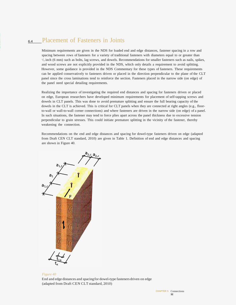
Recommendations on the end and edge distances and spacing for dowel-type fasteners driven on edge (adapted from Draft CEN CLT standard, 2010) are given in Table 1. Definition of end and edge distances and spacing are shown in Figure 40.
Figure 40 End and edge distances and spacing for dowel-type fasteners driven on edge (adapted from Draft CEN CLT standard, 2010)
CHAPTER 5 Connections 32
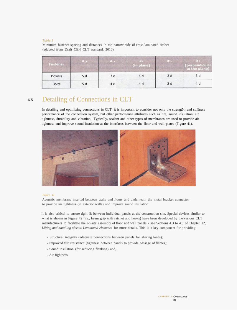
Table 1 Minimum fastener spacing and distances in the narrow side of cross-laminated timber (adapted from Draft CEN CLT standard, 2010)
6.5 Detailing of Connections in CLT In detailing and optimizing connections in CLT, it is important to consider not only the strengt5h and stiffness performance of the connection system, but other performance attributes such as fire, sound insulation, air tightness, durability and vibration,. Typically, sealant and other types of membranes are used to provide air tightness and improve sound insulation at the interfaces between the floor and wall plates (Figure 41).
Figure 41
Acoustic membrane inserted between walls and floors and underneath the metal bracket connector to provide air tightness (in exterior walls) and improve sound insulation
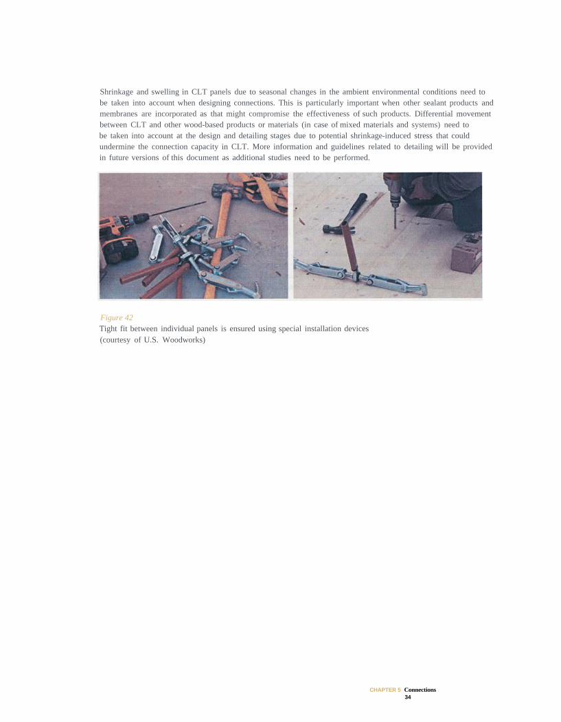
It is also critical to ensure tight fit between individual panels at the construction site. Special devices similar to what is shown in Figure 42 (i.e., beam grip with ratchet and hooks) have been developed by the various CLT manufacturers to facilitate the on-site assembly of floor and wall panels - see Sections 4.3 to 4.5 of Chapter 12, Lifting and handling ofcross-Laminated elements, for more details. This is a key component for providing:
- Structural integrity (adequate connections between panels for sharing loads);
- Improved fire resistance (tightness between panels to provide passage of flames);
- Sound insulation (for reducing flanking) and,
- Air tightness.
CHAPTER 5 Connections 33
Shrinkage and swelling in CLT panels due to seasonal changes in the ambient environmental conditions need to be taken into account when designing connections. This is particularly important when other sealant products and membranes are incorporated as that might compromise the effectiveness of such products. Differential movement between CLT and other wood-based products or materials (in case of mixed materials and systems) need to be taken into account at the design and detailing stages due to potential shrinkage-induced stress that could undermine the connection capacity in CLT. More information and guidelines related to detailing will be provided in future versions of this document as additional studies need to be performed.
Figure 42 Tight fit between individual panels is ensured using special installation devices (courtesy of U.S. Woodworks)
CHAPTER 5 Connections 34
7 DESIGN EXAMPLES
7.1 Example 1: Bolted Lateral Connection in Clt Face Lamination
7.1.1 Metal Plate Connection to CLT
3-ply grade E2 CLT (three times 1.5”plies = 4.5”, see Figure), specific gravity (G) = 0.50 1/4” steel plate, ASTM A36 steel, Fe = 87,000 psi
1” bolt with washers on each end, Fyb = 45,000 psi
Design Design for short-term loading (CD=1.6)
CM=1.0, Ct=1.0, Cg=1.0,
From NDS Table 11.3.3:
= 5600 psi
= 2250 psi
In this example, loading at the shear plane will be parallel to grain in the CLT. The bearing length of the fastener must be reduced.
Bearing length in wood:
(NDS 11.3.5)
Adjusted bearing length for lateral calculations:
CHAPTER 5 Connections 35
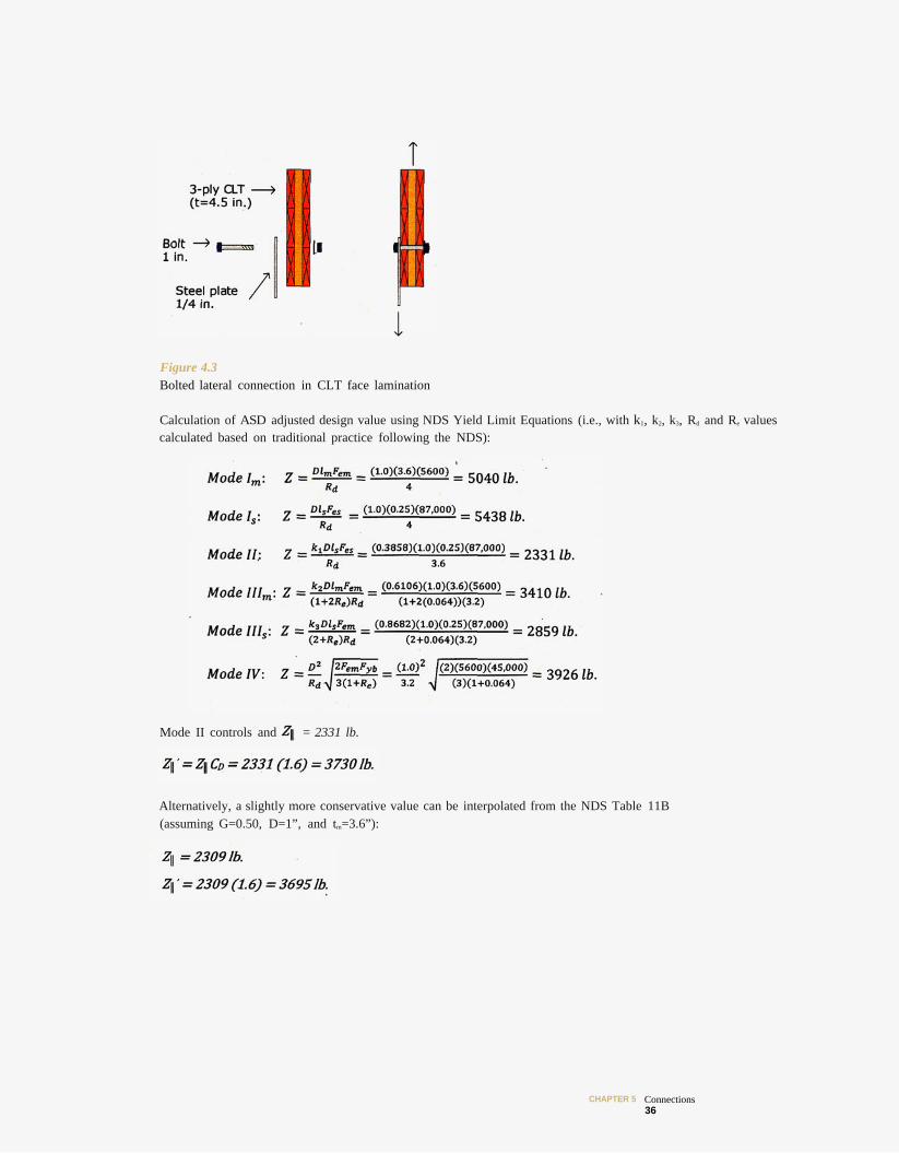
Figure 4.3 Bolted lateral connection in CLT face lamination
Calculation of ASD adjusted design value using NDS Yield Limit Equations (i.e., with k1, k2, k3, Rd and Re values calculated based on traditional practice following the NDS):
Mode II controls and = 2331 lb.
Alternatively, a slightly more conservative value can be interpolated from the NDS Table 11B (assuming G=0.50, D=1”, and tm=3.6”):
CHAPTER 5 Connections 36

7.2 Example 2: Lag Screw Lateral Connection in CLT Face Lamination
7.2.1 Design of Half-lapped Joint for Shear Parallel to the Face Grain of the Panels
Materials
3-ply grade E1 CLT (three times 1.375” plies = 4.125”, see Figure), specific gravity (G) = 0.42
3/8” lag screws, root diameter (Dr) = 0.265” lag screw legnth (L) = 4”
Tip length (E) = 0.22”, Fyb = 45,000 psi
Design
Design for short-term loading (CD=1.6)
From NDS Table 11.3.3:
Figure 44 Lateral resistance of half-lapped joint using lag screws
In this example, the grain orientation at the joint is perpendicular to the face grain of the CLT; therefore, loading of the lag screw at the shear plane will be perpendicular to grain. While the bearing length of the fastener can be adjusted, it is not required. For purposes of the example, both solutions will be provided.
CHAPTER 5 Connections
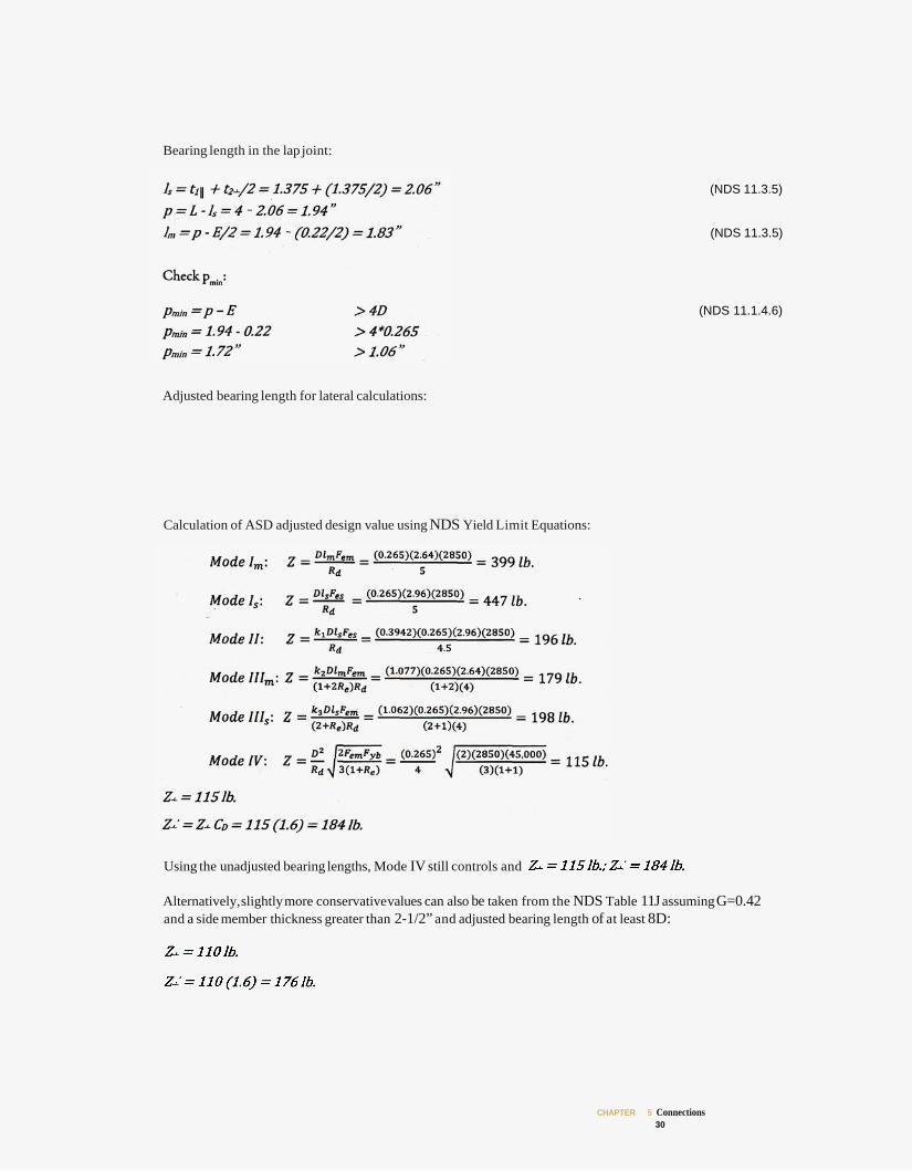
Bearing length in the lap joint:
(NDS 11.3.5)
(NDS 11.3.5)
(NDS 11.1.4.6)
Adjusted bearing length for lateral calculations:
Calculation of ASD adjusted design value using NDS Yield Limit Equations:
Using the unadjusted bearing lengths, Mode IV still controls and
Alternatively,slightly more conservativevalues can also be taken from the NDS Table 11J assuming G=0.42 and a side member thickness greater than 2-1/2” and adjusted bearing length of at least 8D:
CHAPTER 5 Connections 30
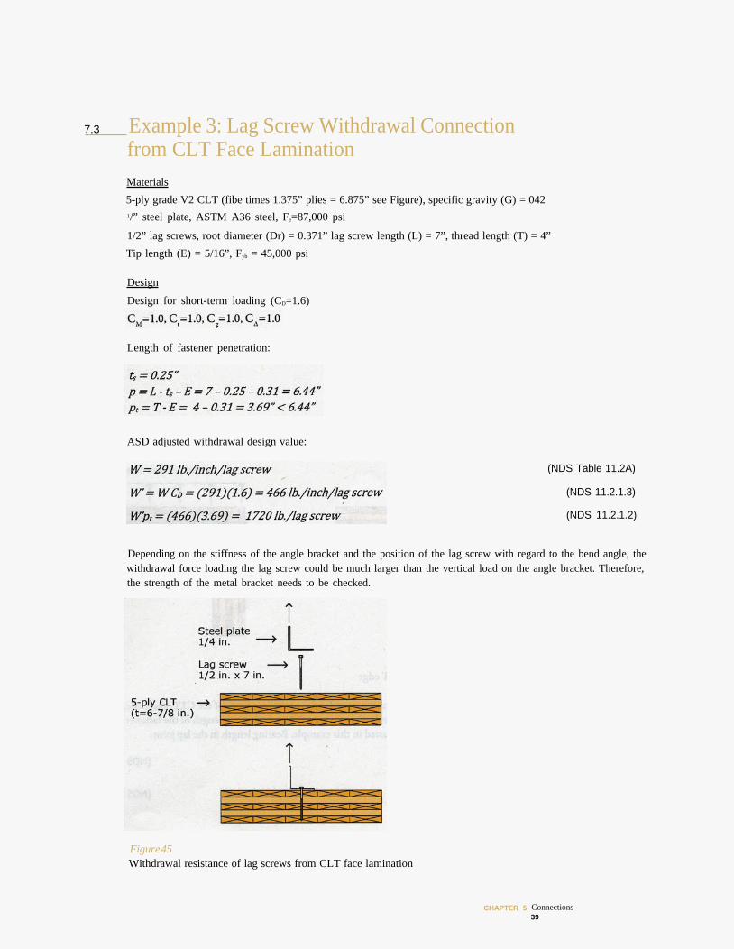
7.3 Example 3: Lag Screw Withdrawal Connection from CLT Face Lamination Materials
5-ply grade V2 CLT (fibe times 1.375” plies = 6.875” see Figure), specific gravity (G) = 042 1/” steel plate, ASTM A36 steel, Fe=87,000 psi
1/2” lag screws, root diameter (Dr) = 0.371” lag screw length (L) = 7”, thread length (T) = 4”
Tip length (E) = 5/16”, Fyb = 45,000 psi
Design
Design for short-term loading (CD=1.6)
Length of fastener penetration:
ASD adjusted withdrawal design value:
(NDS Table 11.2A)
(NDS 11.2.1.3)
(NDS 11.2.1.2)
Depending on the stiffness of the angle bracket and the position of the lag screw with regard to the bend angle, the withdrawal force loading the lag screw could be much larger than the vertical load on the angle bracket. Therefore, the strength of the metal bracket needs to be checked.
Figure 45 Withdrawal resistance of lag screws from CLT face lamination
CHAPTER 5 Connections 39
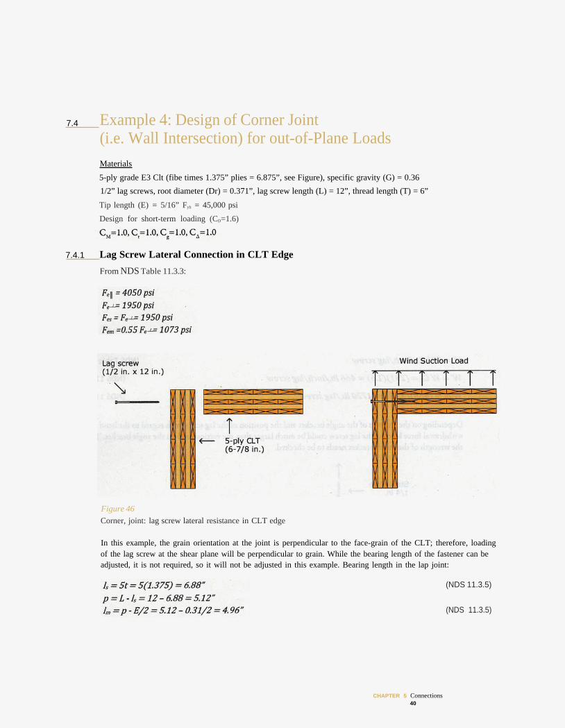
7.4 Example 4: Design of Corner Joint (i.e. Wall Intersection) for out-of-Plane Loads Materials
5-ply grade E3 Clt (fibe times 1.375” plies = 6.875”, see Figure), specific gravity (G) = 0.36
1/2” lag screws, root diameter (Dr) = 0.371”, lag screw length (L) = 12”, thread length (T) = 6”
Tip length (E) = 5/16” Fyb = 45,000 psi
Design for short-term loading (CD=1.6)
7.4.1 Lag Screw Lateral Connection in CLT Edge
From NDS Table 11.3.3:
Figure 46 Corner, joint: lag screw lateral resistance in CLT edge
In this example, the grain orientation at the joint is perpendicular to the face-grain of the CLT; therefore, loading of the lag screw at the shear plane will be perpendicular to grain. While the bearing length of the fastener can be adjusted, it is not required, so it will not be adjusted in this example. Bearing length in the lap joint:
(NDS 11.3.5)
(NDS 11.3.5)
CHAPTER 5 Connections 40
Check pmin:
(NDS 11.1.4.6)
Calculation of ASD adjusted design value using NDS Yield Limit Equations:
It should be noted that the loaded edge is prone to splitting. A splitting check of the panel with the screws inserted in the edge may be required. Alternatively, reinforcing the panel with fully threaded self-tapping screws is advisable.
7.4.2 Lag Screw Withdrawal Connection in CLT Edge
Length of fastener penetration:
ASD adjusted withdrawal design value:
(NDS Table 11.2A)
(NDS 11.2.1.3)
(NDS 11.2.1.2)
CHAPTER 5 Connections 41
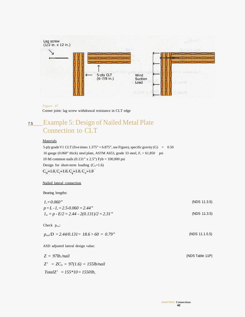
Figure 47 Corner joint: lag screw withdrawal resistance in CLT edge
Example 5: Design of Nailed Metal Plate Connection to CLT Materials
5-ply grade V1 CLT (five times 1.375” = 6.875”, see Figure), specific gravity (G) = 0.50
16 gauge (0.060” thick) steel plate, ASTM A653, grade 33 steel, Fe = 61,850 psi
10 8d common nails (0.131” x 2.5”) Fyb = 100,000 psi
Design for short-term loading (CD=1.6)
Nailed lateral connection
Bearing lengths:
1s =0.060” p = L -1s = 2.5-0.060 = 2.44” 1m = p - E/2 = 2.44 - 2(0.131)/2 = 2.31”
Check pmin:
pmin/D = 2.44/0.131= 18.6 > 60 = 0.79”
ASD adjusted lateral design value:
Z = 97lb./nail
Z’ = ZCD = 97(1.6) = 155lb/nail
(NDS 11.3.5)
(NDS 11.3.5)
(NDS 11.1.5.5)
(NDS Table 11P)
TotalZ’ = 155*10 = 1550lb,
CHAPTER 5 Connections 42
7.5
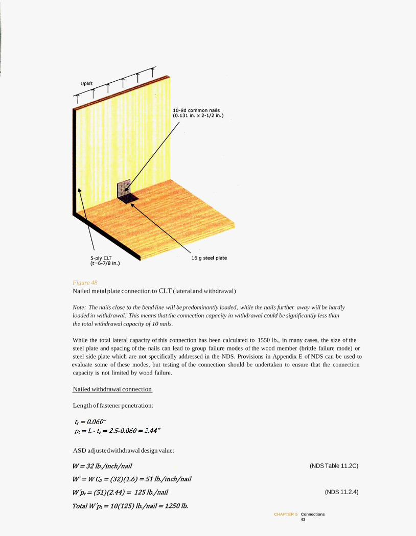
Figure 48 Nailed metal plate connection to CLT (lateral and withdrawal)
Note: The nails close to the bend line will be predominantly loaded, while the nails further away will be hardly loaded in withdrawal. This means that the connection capacity in withdrawal could be significantly less than the total withdrawal capacity of 10 nails.
While the total lateral capacity of this connection has been calculated to 1550 lb., in many cases, the size of the steel plate and spacing of the nails can lead to group failure modes of the wood member (brittle failure mode) or steel side plate which are not specifically addressed in the NDS. Provisions in Appendix E of NDS can be used to evaluate some of these modes, but testing of the connection should be undertaken to ensure that the connection capacity is not limited by wood failure.
Nailed withdrawal connection
Length of fastener penetration:
ASD adjustedwithdrawal design value:
(NDS Table 11.2C)
(NDS 11.2.4)
CHAPTER 5 Connections 43
Connections in timber construction, including those built with CLT, play an important role in maintaining the integrity of the timber structure and in providing strength, stiffness, stability and ductility. Consequently, they require detailed attention by designers.
Traditional and innovative connection systems have been used in CLT assemblies in Europe. Several types of traditional and innovative connection systems for connecting CLT panels to panels, walls to walls and walls to floors are described in detail in this Chapter. They are mostly based on the European experience.
Researchers in Europe have developed design procedures for traditional connections in CLT, including dowels, wood screws and nails which are commonly used in Europe for designing CLT assemblies. The proposed design procedure deals only with ductile failure modes to determine the lateral load resistance of such connections. Expressions were developed for the calculation of characteristic dowel-bearing properties of each type of fastener, depending on its location with respect to the plane of the panel (perpendicular to or on edge). The expressions were verified and results seem to correspond well with predictions. European Yield Model equations for ductile failure modes as given in Eurocode 5 were adopted for design using CLT fastener dowel-bearing equations.
Due to the reinforcing effect of cross lamination in CLT, it is speculated that current minimum geometric requirements given in the NDS for dowels, screws and nails in solid timber or glulam are applicable to CLT. However, designers need to be cautious about this as further verification is required, considering the specific features of each panel. Brittle failure modes need also to be taken into account and have not yet been investigated. Further work is needed to verify possible brittle failure modes associated with each type of fasteners in CLT connections as well as their behavior for seismic design.
CHAPTER 5 Connections 44
9 REFERENCES
American Forest & Paper Association (AF&PA). 20 12. National design specification (NDS) for wood construction commentary. Washington, DC: AF&PA.
Augustin, M., ed. 2008. Timber structures. Handbook 1 of Educational materials for designing and testing of timber structures: TEMTIS. Leonardo da Vinci Pilot Project No. CZ/06/B/F/PP/168007. Ostrava, Czech Republic: VSB-Technical University of Ostrava.
European Committee for Standardization (CEN). 2004. Eurocode 5: Design of timber structures. Part 1-1: General- Common rules and rules for buildings. EN 1995-1-1. Brussels: CEN.
.2011. Timber structures - Cross laminated timber - Requirements. Draft European Standard. Brussels: CEN/TC 124.
Gagnon, S. and C. Pirvu, eds. 2011. CLT Handbook : Cross-laminated timber. Canadian ed. Special Publication SP-528E. Québec, QC: FPInnovations. 1 v.
Mohammad, M., and W. Munoz. 2011. Connections in cross-laminated timber buildings. In CLT handbook, ed. S. Gagnon and C. Pirvu. Chapter 5. Québec, QC: FPInnovations.
TRADA. 2009. Cross laminated timber: Structural principles. High Wycombe, UK: TRADA.
Traetta, G. 2007. Connection Techniques for CLT elements. Paper presented at the Temtis Austrian Country Seminar: Cross-Laminated Timber, Graz, Austria.
Uibel, T., and H.J. Blass.2006. Load carrying capacity of joints with dowel type fasteners in solid wood panels. Paper presented at the 39th meeting of the Working Commission W18 - Timber Structures, International Council for Research and Innovation in Building and Construction, Florence, Italy, August 2006.
.2007. Edge joints with dowel type fasteners in cross laminated timber. Paper presented at the 40th meeting of the Working Commission W18 - Timber Structures, International Council for Research and Innovation in Building and Construction, Bled, Slovenia, August 2007.
CHAPTER 5 Connections 45

© 2013 FPlnnovations and Binational Softwood Lumber Council. All rights reserved.
The U.S. Edition of the CLT Handbook: cross-laminated timber can be electronically downloaded without charge from the website www.masstimber.com. Additional information can be obtained by visiting the websites of FPlnnovations, USFPL, American Wood Council (AWC), APA and U.S. WoodWorks. Hard copies can be obtained through AWC (www.awc.org).
No part of this published Work may be reproduced, published, or transmitted for commercial purposes, in any form or by any means, electronic, mechanical, photocopying, recording or otherwise, whether or not in translated form, without the prior writ ten permission of FPlnnovations and Binational Softwood Lumber Council.
The information contained in this Work represents current research results and technical information made available from many sources, including researchers, manufacturers, and design professionals. The information has been reviewed by professionals in wood design including professors, design engineers and architects, and wood product manufacturers. While every reasonable effort has been made to insure the accuracy o f the information presented, and special effort has been made to assure that the information reflects the state-of-the-art, none of the above-mentioned parties make any warranty, expressed or implied. or assume any legal liability or responsibility for the use, application of, and/or reference to opinions, findings, conclusions, or recommendations included in this published work, nor assume any responsibility for the accuracy or completeness of the information or i t s fitness for any particular purpose.
This published Work is designed to provide accurate, authoritative information but is not intended to provide professional advice. It is the responsibility of users to exercise professional knowledge and judgment in the use of the information.

Edited bv Erol Karacabeyli, P.Eng., FPlnnovations
Brad Douglas, P.E., AWC
FPlnnovations Pointe-Claire, QC
Special Publication SP-529E
201 3
Library and Archives Canada Cataloguing in Publication
CLT handbook: cross-laminated timber / edited by Erol Karacabeyli, Brad Douglas. -- U.S. ed.
(Special publication, ISSN 1925-0495; SP-529E) Co-published by U.S. Department of Agriculture, Forest Service, Forest
Products Laboratory, Binational Softwood Lumber Council (BSLC). Includes bibliographical references. Issued also in electronic format. ISBN978-0-86488-553-1
1. Laminated wood. 2. Laminated wood construction. 3. Engineered wood construction. 4. Laminated wood--Standards. 5. Laminated wood-Handbooks, manuals, etc. I. Karacabeyli, Erol, 1954-II. Douglas, Brad, 1960-III. Forest Products Laboratory (U.S.) IV. FPInnovations (Institute) V. Binational Softwood Lumber Council VI. Title: Cross-laminated timber. VII. Series: Special publication (FPInnovations (Institute)); SP-529E
TA666.C572013 624.1'84 C2012-908154-X
Library and Archives Canada Cataloguing in Publication
CLT handbook [electronic resource]: cross-laminated timber / edited by Erol Karacabeyli, Brad Douglas. -- U.S. ed.
(Special publication, ISSN 1925-0509; SP-529E) Co-published by U.S. Department of Agriculture, Forest Service, Forest
Products Laboratory, Binational Softwood Lumber Council (BSLC). Includes bibliographical references. Electronic monograph in PDF format. Issued also in print format. ISBN 978-0-86488-554-8
1. Laminated wood. 2. Laminated wood construction. 3. Engineered wood construction. 4. Laminated wood--Standards. 5. Laminated wood-Handbooks, manuals, etc. I. Karacabeyli, Erol, 1954-II. Douglas, Brad, 1960-III. Forest Products Laboratory (U.S.) IV. FPInnovations (Institute) V. Binational Softwood Lumber Council VI. Title: Cross-laminated timber. VII. Series: Special publication (FPInnovations (Institute) : Online) ; SP-529E
TA666.C57 2013 624.1'84 C2012-908155-8

![Blue Cross Complete of Michigan Connections · Blue Cross Complete of Michigan CONNECTIONS | 1 CONNECTIONS March/April 2018 ... antibody, syphilis test, RBC antibody screen, Rh[D]](https://img.pdfslide.us/doc/110x75/5f07d20f7e708231d41eea3c/blue-cross-complete-of-michigan-connections-blue-cross-complete-of-michigan-connections.jpg)