Embed Size (px)
Citation preview

Chapter 4
TECHNOLOGY
Photo credit: Federa/ Aviation Administration 1

Contents
The Airport and its Components . . . . . . . . . . . . . . . . . . . . . . . . . . . . . . . . . . . . . . . . . . . . . . . . .Airport and Airspace Technology . . . . . . . . . . . . . . . . . . . . . . . . . . . . . . . . . . . . . . . . . . . . . . . .Guidance, Surveillance, and Control . . . . . . . . . . . . . . . . . . . . . . . . . . . . . . . . . . . . . . . . . . . . . .
Microwave Landing System. . . . . . . . . . . . . . . . . . . . . . . . . . . . . . . . . . . . . . . . . . . . . . . . . . . .Surveillance Radar. . . . . . . . . . . . . . . . . . . . . . . . . . . . . . . . . . . . . . . . . . . . . . . . . . . . . . . . . . . .Traffic Management Techniques . . . . . . . . . . . . . . . . . . . . . . . . . . . . . . . . . . . . . . . . . . . . . . . .Supporting Technologies . . . . . . . . . . . . . . . . . . . . . . . . . . . . . . . . . . . . . . . . . . . . . . . . . . . . . .
Airspace Use Procedures . . . . . . . . . . . . . . . . . . . . . . . . . . . . . . . . . . . . . . . . . . . . . . . . . . . . . . . .Reduced Lateral Separation . . . . . . . . . . . . . . . . . . . . . . . . . . . . . . . . . . . . . . . . . . . . . . . . . . . .Reduced Longitudinial Separation on Final Approach . . . . . . . . . . . . . . . . . . . . . . . . . . . . .Separate Short Runways for Small Aircraft. . . . . . . . . . . . . . . . . . . . . . . . . . . . . . . . . . . . . .
Weather and Atmospheric Effects . . . . . . . . . . . . . . . . . . . . . . . . . . . . . . . . . . . . . . . . . . . . . . . . .Wake Vortex . . . . . . . . . . . . . . . . . . . . . . . . . . . . . . . . . . . . . . . . . . . . . . . . . . . . . . . . . . . . . . . .Wind Shear . . . . . . . . . . . . . . . . . . . . . . . . . . . . . . . . . . . . . . . . . . . . . . . . . . . . . . . . . . . . . . . . . .
Noise Control and Abatement . . . . . . . . . . . . . . . . . . . . . . . . . . . . . . . . . . . . . . . . . . . . . . . . . . .Aircraft Noise.... . . . . . . . . . . . . . . . . . . . . . . . . . . . . . . . . . . . . . . . . . . . . . . . . . . . . . . . . . . . .Aircraft Operating Procedures . . . . . . . . . . . . . . . . . . . . . . . . . . . . . . . . . . . . . . . . . . . . . . . . .
Airport Surface Uilization . . . . . . . . . . . . . . . . . . . . . . . . . . . . . . . . . . . . . . . . . . . . . . . . . . . . . . .Surveillance and Control . . . . . . . . . . . . . . . . . . . . . . . . . . . . . . . . . . . . . . . . . . . . . . . . . . . . . .Taxiways . . . . . . . . . . . . . . . . . . . . . . . . . . . . . . . . . . . . . . . . . . . . . . . . . . . . . . . . . . . . . . . . . . . .Apron and Gate Facilities . . . . . . . . . . . . . . . . . . . . . . . . . . . . . . . . . . . . . . . . . . . . . . . . . . . . .Terminal Facilities and Services . . . . . . . . . . . . . . . . . . . . . . . . . . . . . . . . . . . . . . . . . . . . . . . .Terminal Building Design.. . . . . . . . . . . . . . . . . . . . . . . . . . . . . . . . . . . . . . . . . . . . . . . . . . . . .Terminal Services . . . . . . . . . . . . . . . . . . . . . . . . . . . . . . . . . . . . . . . . . . . . . . . . . . . . . . . . . . . .
Landside Access . . . . . . . . . . . . . . . . . . . . . . . . . . . . . . . . . . . . . . . . . . . . . . . . . . . . . . . . . . . . . . . .Terminal Curbfront . . . . . . . . . . . . . . . . . . . . . . . . . . . . . . . . . . . . . . . . . . . . . . . . . . . . . . . . . . .Airport Ground Access.. . . . . . . . . . . . . . . . . . . . . . . . . . . . . . . . . . . . . . . . . . . . . . . . . . . . . . .
Applications of Technology to Airport Problems . . . . . . . . . . . . . . . . . . . . . . . . . . . . . . . . . . .
60
60
626266687 0
71717476
767 77 7
798 081
8 38 38 48 68 6889 0
9 39 59 6
9 7Capacity and Delay Problems at Selected Airports . ..............................100Prospective Technological Solutions . . . . . . . . . . . . . . . . . . . . . . . . . . . . . . .,. ...........101
List of Tables
Table Page13. Technology To Increase Airport Capacity and Reduce Delay . . . . . . . . . . . . . . . . . . . . . 6314. Summary of NAS Plan Benefits and Costs . . . . . . . . . . . . . . . . . . . . . . . . . . . . . . . . . . . . . 69IS. Airport Capacity Survey . . . . . . . . . . . . . . . . . . . . . . . . . . . . . . . . . . . . . . . ..............10216. Airport Technology Summary . . . . . . . . . . . . . . . . . . . . . . . . . . . . . . . .................104
List of Figures
Figure Pagey. Airport Components . . . . . . . . . . . . . . . . . . . . . . . . . . . . . . . . . . . . . . . . . . . . . . . . . . . . . . . . 618. Comparison of Microwave Landing System and Instrument Landing System . . . . . . . 659. Arrival and Departure Separations . . . . . . . . . . . . . . . . . . . . . . . . . . . . . . . . . . . . . . . . . . . . 75
10, Effects of Low-Altitude Wind Shear . . . . . . . . . . . . . . . . . . . . . . . . . . . . . . . . . . . . . . . . . . . 7811. Airport Landside Functional Flow . . . . . . . . . . . . . . . . . . . . . . . . . . . . . . . . . . . . . . . . . . . . . 8712. Airport Terminal Design Concepts . . . . . . . . . . . . . . . . . . . . . . . . . . . . . . . . . . . . . . . . . . . . 893.3. Federal Capital Funding of Airports and Related Facilities . . . . . . . . . . . . . . . . . . . . . . . . 9514. Zurich Airport and Rail Terminal Complex . . . . . . . . . . . . . . . . . . . . . . . . . . . . . . . . . . . . 9815. Off-Site passenger Terminal Concepts . . . . . . . . . . . . . . . . . . . . . . . . . . . . . . . . . . . . . . . . . 99

Chapter 4
TECHNOLOGY’
The airport system in place in the United Statestoday is extensive and highly developed; in gen-eral, it serves the Nation well. Still, there areproblems of congestion and delay at the busiestairports, where facilities are not adequate to ac-commodate demand at all times and in all condi-tions of weather and visibility. The Federal Avia-tion Administration (FAA) forecasts that growthof commercial and private aviation could be con-strained by lack of airport capacity, which it con-siders to be the most serious problem facing civilaviation through the remainder of this century. z
Recent policy statements by FAA acknowledgethat, with a few exceptions, the direct solutionof building new airports and expanding existingones may not be practical due to lack of suitablenew airport sites, physical limitations of presentfacilities, and concerns about environmental im-pacts of aviation on surrounding communities.3
Similar views have been expressed in two recentstudies of airport capacity,4 5 and there is a widelyheld opinion that, while the airport system is ex-pandable in the broad sense, there is little hopeof creating major new facilities in those key metro-politan areas where air travel demand and avia-tion activity continue to outstrip available airportcapacity unless airport planners can persuade sur-rounding communities that airports can be goodneighbors.
For this reason, the aviation community andFAA have sought technological solutions that will
IThis chapter is based on material prepared for OTA by Landrum& Brown, Inc.
‘National Airspace System Plan, revised edition (Washington, DC:Federal Aviation Administration, April 1983), p. 11-10.
31bid., p. I-5.4Report of the Industry Task Force on Airport Capacity Improve-
rnent and Delay Reduction (Washington, DC: Airport OperatorsCouncil International, September 1982).
5Report and Recommendations of the Airport Access Task Force(Washington, DC: Civil Aeronautics Board, March 1983).
ease congestion by allowing fuller and more effi-cient use of the airports we already have. Thistechnology includes new equipment for surveil-lance, navigation, and communication and revisedprocedures for using the airspace and airport fa-cilities. In this way, it is hoped that additional de-mand can be absorbed within the infrastructurenow in place, without adversely affecting sur-rounding communities.
This chapter examines technological measures,either currently available or under development,that could be employed to relieve congestion anddelay. It consists of a survey of possible improve-ments in airport technology, with emphasis on thecircumstances in which this technology would beapplicable, the extent to which it could increasethe amount of traffic handled, and the prospectsfor development and deployment over the com-ing years.
In aviation, the term technology typically bringsto mind sophisticated electronic and mechanicaldevices used for navigation, surveillance, com-munication, and flight control. Such devices areclearly of interest, but for the purposes of this re-port, technology is interpreted in a broader sense.As used here, technology refers not only to newdevices and equipment but also to new opera-tional concepts and procedures that they makepossible. Also, many in the aviation communitydraw a distinction between technology (meaningequipment and sometimes procedures) and civilengineering (referring to the design and construc-tion of physical components of the airport—theconcrete, so to speak). While recognizing that dif-ferent engineering disciplines and techniques areinvolved, this report does not make such a ciistinc-tion and considers the design and construction ofimproved physical components such as runways,taxiways, and terminal buildings as simply onemore form of technology that will add to airportcapacity or permit more effective and economi-cal use of the airport as a whole.
59

—.
60 . Airport System Development— — . —
THE AIRPORT AND ITS COMPONENTS
The airport is a complex transportation hubserving aircraft, passengers, cargo, and surfacevehicles. It is customary to classify the severalcomponents of an airport in three major catego-ries: airside facilities; landside facilities; and theterminal building, which serves as the interchangebetween the two’ (see fig. 7).
Airside components, sometimes called the aero-nautical surfaces, or more simply the airfield, arethose on which aircraft operate. Principally, theyare the runways where aircraft take off and land,the taxiways used for movement between the run-way and the terminal, and the apron and gateareas where passengers embark and debark andwhere aircraft are parked. Because the airspacecontaining the approach and departure paths forthe airfield has an important effect on runway uti-lization, it is also customary to include terminalarea airspace as part of the airside.
The terminal consists primarily of the buildingsserving passengers and is made up of passengerloading and waiting areas, ticket counters, bag-— — —
6 Some experts do not employ this tripartite classification. For ex-ample, R. Horonjeff and F. X. McKelvey, Planning and Design ofAirports (New York: McGraw Hill, 3d cd., 1983), distinguish onlybetween the airside and the landside, making the division at thepassenger loading gates and including the terminal as part of thelandside.
gage handling facilities, restaurants, shops, carrental facilities, and the like. Loading, handling,and storage areas for air cargo and mail, oftenseparately located, are also part of the terminalcomplex.
The landside is essentially that part of the air-port devoted to surface transportation. It beginsat the curbside of the terminal building and in-cludes roadways, parking facilities, and—in somecases—rail rapid transit lines and stations that arepart of a larger urban mass transit system. Cus-tomarily, only roadways and transportation fa-cilities on the airport property are considered partof the landside, even though they are actually ex-tensions of, and integral with, the urban and re-gional transportation network.
In the discussion that follows, attention is fo-cused initially on those airside components wherecapacity and delay problems tend to be severe.The landside and terminal areas are not trouble-free, however, and congestion of these facilitiescan have an important effect on the overall ca-pacity of the airport. An examination of possi-ble technological improvements in terminals andlandside access is included at the end of thischapter.
AIRPORT AND AIRSPACE TECHNOLOGY
Technological approaches to expanding airportcapacity or reducing delay fall into three broadcategories. First, there are improved devices andprocedures that will expedite the flow of air traf-fic into and out of the airport—i.e., techniquesthat will augment airside capacity or mitigate air-craft delay by increasing the runway operationrate. The second category includes techniques tofacilitate movement of aircraft on the airport sur-face. The purpose of these technologies is to moveaircraft from the runway to the passenger loadinggates and back again as expeditiously as possi-ble, thereby shortening the taxi-in and taxi-outcomponents of delay and easing congestion ontaxiways, aprons, and loading ramps. The thirdcategory embraces techniques that can be used toaid the transit of passengers through the terminal
building and the flow of vehicles on airport cir-culation and access roads. In contrast with the firsttwo categories, where the aim is to alleviate air-craft delay, the third category is intended to fa-cilitate the movement of people and to reduce thatpart of delay incurred in getting to and fromaircraft.
Thus, the survey that follows addresses thebroad question of airport capacity, not just air-side capacity or aircraft delay. The intent is toexamine ways to improve the overall adequacyand efficiency of the airport as a transportationhub. The underlying proposition is that delay–any form of delay—ultimately affects the passen-ger through loss of time and increased cost of airtransportation service. In this sense, it is parochial

Ch. 4—Techno/ogy ● 61
///////////t
Figure 7.—Airport Components
SOURCE Federal Avlatlon Admlnlstratlon
62 Airport System Development
to speak only of aircraft delay since the basic pur-pose of the air transportation system is to movepeople from origin to destination, in safety, withminimum expenditure of time and money. Allmeasures taken at airports to shorten travel time,to lower travel cost, or to lessen inconvenienceare of equal importance, regardless of whetherthey apply to the airside, the landside, or passagethrough the terminal.
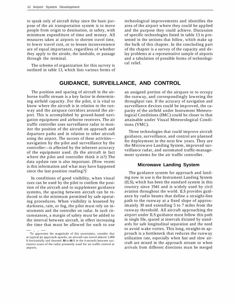
The scheme of organization for this survey isoutlined in table 13, which lists various forms of
technological improvements and identifies thearea of the airport where they could be appliedand the purpose they could achieve. Discussionof specific technologies listed in table 13 is pre-sented in the sections that follow, which make upthe bulk of this chapter. In the concluding partof the chapter is a survey of the capacity and de-lay problems at a representative sample of airportsand a tabulation of possible forms of technologi-cal relief.
GUIDANCE, SURVEILLANCE, AND CONTROL
The position and spacing of aircraft in the air-borne traffic stream is a key factor in determin-ing airfield capacity. For the pilot, it is vital toknow where the aircraft is in relation to the run-way and the airspace corridors around the air-port. This is accomplished by ground-based navi-gation equipment and airborne receivers. The airtraffic controller uses surveillance radar to mon-itor the position of the aircraft on approach anddeparture paths and in relation to other aircraftusing the airport. The success of these activities—navigation by the pilot and surveillance by thecontroller—is affected by the inherent accuracyof the equipment used. (Is the aircraft in factwhere the pilot and controller think it is?) Thedata update rate is also important. (How recentis this information and what may have happenedsince the last position reading?)7
In conditions of good visibility, when visualcues can be used by the pilot to confirm the posi-tion of the aircraft and to supplement guidancesystems, the spacing between aircraft can be re-duced to the minimum permitted by safe operat-ing procedures. When visibility is lessened bydarkness, rain, or fog, the pilot must rely on in-struments and the controller on radar. In such cir-cumstances, a margin of safety must be added tothe interval between aircraft, in effect increasingthe time that must be allowed for each to use— . . —
‘To appreciate the magnitude of this uncertainty, consider thatat typical jet approach speeds, an aircraft can travel almost 1,000ft horizontally and descend 50 to 60 ft in the 4 seconds between suc-cessive scans of the radar presently used for air traffic control atairports.
an assigned portion of the airspace or to occupythe runway, and correspondingly lowering thethroughput rate. If the accuracy of navigation andsurveillance devices could be improved, the ca-pacity of the airfield under Instrument Meteoro-logical Conditions (IMC) could be closer to thatattainable under Visual Meteorological Condi-tions (VMC).
Three technologies that could improve aircraftguidance, surveillance, and control are plannedfor deployment in the next few years. They arethe Microwave Landing System, improved sur-veillance radar, and automated traffic-manage-ment systems for the air traffic controller.
Microwave Landing System
The guidance system for approach and land-ing now in use is the Instrument Landing System(ILS), which has been the standard system in thiscountry since 1941 and is widely used by civilaviation throughout the world. ILS provides guid-ance by radio beams that define a straight-linepath to the runway at a fixed slope of approx-imately 30 and extending 5 to 7 miles from therunway threshold. All aircraft approaching theairport under ILS guidance must follow this pathin single file, spaced at intervals dictated by stand-ards for safe longitudinal separation and the needto avoid wake vortex. This long, straight-in ap-proach is a bottleneck that reduces the runwayutilization rate, especially when fast and slow air-craft are mixed in the approach stream or whenarrivals from different directions must be merged
Ch. 4—Technology . 63
Table 13.–Technology To Increase Airport Capacity and Reduce Delay
Area ofapplicationTechnology
Aircraft guidance, surveillance, and control:Microwave Landing System . . . . . . . . . . . . . . . .
Purpose Benefit
Improve precision ofnavigation; make moreflexible use of airspace
Improve surveillance; reduceseparation
Improve traffic flow
Increased capacity; reduceddelay; less noise impact
Airspace
Surveillance radar . . . . . . . . . . . . . . . . . . . . . . . . Airspace
Airspace
Improved safety; increasedcapacity
Reduced delayTraffic management techniques . . . . . . . . . . . .
Airspace use procedures:Reduced lateral separation for parallel and
converging runways Airspace
AirspaceAirspace
Increase utilization of multiplerunways in IMC
Reduce in-trail separationSegregate air traffic by size
and speed
Increased capacity
Reduced longitudinal separation . . . . . . . . . . .Separate short runways for small aircraft . . . .
Increased capacityIncreased capacity; reduced
delay
Weather and atmospheric effects:Wake vortex detection . . . . . . . . . . . . . . . . . . . .Wind shear detection . . . . . . . . . . . . . . . . . . . . .
AirspaceAirspace
Reduce in-trail separationAlert pilots to wind shear
Increased capacityImproved safety; reduced
delay
Noise control and abatement:Control of aircraft noise . . . . . . . . . . . . . . . . . . . Reduce aircraft noise Increased capacity; reduced
delayIncreased capacity: reduced
delay
Airspace
AirspaceAircraft operating procedures . . . . . . . . . . . . . . Lessen or distribute noiseimpacts
Airport surface utilization:Surveillance and control . . . . . . . . . . . . . . . . . . . Taxi ways Improve surveillance, control,
and guidance of aircrafton ground
Reduce runway occupancytime
Increase efficiency of taxiwayuse
Improve docking at gate;improve aircraftmaintenance and servicing
Increased capacity; reduceddelav; improved safety
High-speed turnoffs and improved taxiways. .
Taxiway marking and lighting . . . . . . . . . . . . . .
Apron and gate facilities . . . . . . . . . . . . . . . . . .
Runway
Taxi ways
Ramps andaprons
Increased capacity
Reduced delay
Increased capacity; reduceddelay
Terminal facilities and services:Terminal building design . . . . . . . . . . . . . . . . . . Terminal
Terminal
Increase utility and efficiencyof terminal building
Improve circulation interminal; reduce walkingdistance
Expedite ticket purchase andpassenger check-in
Expedite baggage check-in,transfer, and pickup
Make screening faster andmore reliable
Expedite customs andimmigration clearance
Increased capacity; reduceddelay
Reduced delay; greaterpassenger convenience
Passenger movers . . . . . . . . . . . . . . . . . . . . . . . .
Ticketing . . . . . . . . . . . . . . . . . . . . . . . . . . . . . . . . Terminal
Terminal
Terminal
Terminal
Reduced delay
Reduced delay
Reduced delay;security
Reduced delay
Reduced delay
Reduced delay
Reduced delay
Baggage handling . . . . . . . . . . . . . . . . . . . . . . . .
Passenger security screening . . . . . . . . . . . . . . improved
Federal Inspection Service . . . . . . . . . . . . . . . .
Airport access:Terminal curbfront design . . . . . . . . . . . . . . . . . Terminal;
landsideLandside
Land side
Facilitate airport entranceand exit
Facilitate automobile trafficflow
Reduce access time; lessen
Airport circulation roads . . . . . . . . . . . . . . . . . .
Airport ground access . . . . . . . . . . . . . . . . . . . .road congestion
SOURCE Office of Technology Assessment

64 ● Airport System Development— . . — . — — — — .
on the common final approach path. As a result,the capacity of the airfield under IMC, when thelong ILS common approach path must be used,is usually less than under VMC.
The runway utilization rate under IMC couldcome closer to that attainable under VMC if air-craft could follow multiple approach paths, de-scend at different approach angles, or aim at dif-ferent touchdown points on the runway—noneof which is practical with ILS. If this flexibilitywere possible, as it is under VMC, airfield capa-city would be less affected by weather conditions,and throughput would be governed almost ex-clusively by runway geometry and aircraft per-formance characteristics.
The Microwave Landing System (MLS), whichhas been under development by FAA for over adecade, would overcome some of the disadvan-tages inherent in the ILS. Because MLS uses abeam that scans a wide volume of airspace, ratherthan the pencil beam of ILS, it permits aircraftto fly any of several approach angles (includingtwo-step glide slopes) and, in the horizontal plane,to approach along curving paths that intersect theextension of the runway centerline at any chosenpoint. In effect, MLS offers a degree of freedomin using the airspace that is closer to that enjoyedunder conditions of good visibility (see fig. 8).
The chief motive for FAA in seeking to developand deploy the MLS is not the potential capacitybenefits, however, but its operational advantages—more precise guidance, ease of installation, im-proved reliability, less susceptibility to electro-magnetic interference, and greater number oftransmission channels. The capacity benefits aresecondary but still of great importance at someairports where the present ILS acts to constraincapacity in adverse weather conditions. In termsof its effect on capacity, the chief advantage ofMLS is that, in IMC, it allows pilots and con-trollers greater flexibility in selecting an approachpath so as to shorten the approach time, to avoidair turbulence generated in the wake of precedingaircraft, or to avoid noise-sensitive areas. Anotheradvantage is that MLS can provide guidance forthe aircraft during missed approach, allowing asafe exit from the terminal airspace and smoothreentry into the approach pattern. The availabil-
ity of missed approach guidance could have a sig-nificant capacity benefit at those airports with par-allel or converging runways that cannot now beused in IMC. A third advantage is that MLS canbe installed on runways where ILS is not possi-ble due to siting problems and on short auxiliaryrunways reserved for commuter and small gen-eral aviation (GA) aircraft.8 On some runways,MLS can increase capacity during IMC by pro-viding lower landing minimums than ILS andthereby allowing the airport to remain open inmarginal weather conditions. A fourth advantageof MLS is its capability to provide nonconflictingroutes into closely situated airports, where ap-proach or departure paths may mutually interfereand limit capacity utilization.
The capacity benefits of MLS are highly site-specific—depending on the runway configuration,the prevalence of adverse weather, the mix of air-craft using the airport, and the extent to whichthese aircraft are equipped with MLS receivers.Estimates by FAA indicate that the benefits couldrange up to 10 or 15 percent greater capacity atsome airports under IMC. The overall effects oncapacity at these airports would be somewhatsmaller since they depend on how often Instru-ment Meteorological Conditions occur. The neteconomic benefits are estimated by FAA to be$500 million over a 20-year period (1976 dollars),principally to air carriers and commuter airlinesin the form of reduced delay costs and savingsof passenger time.9
This estimate has been challenged in a recentreport by the Industry Task Force on Airport Ca-pacity Improvement and Delay Reduction. TheTask Force found that the chief advantages wereat small or remote airports served by helicoptersand commuter airlines and in high-density traf-fic areas where MLS could permit commuter air-craft to approach and land on separate short run-
6For a further discussion of MLS technology and its benefits, seeAirport and Air Traffic Control System (Washington, DC: U.S. Con-gress, Office of Technology Assessment, OTA-STI-175, January1982), pp. 92-96, 117; and Improving the Air Traffic Control System:An Assessment of the National Airspace System Plan (Washington,DC: Congressional Budget Office, August 1983), pp. 9-18.
‘An Analysis of the Requirements for, and the Benefits and Costsof the National Microwave Landing System (MLS), FAA-EM-80-7(Washington, DC: Federal Aviation Administration, June 1980).

Ch. 4—Technology ● 6 5
Figure 8.—Comparison of Microwave Landing System and Instrument Landing System
4 0- wide t W “(
Instrument landing system
No continuous distancemeasurement two discrete range Aindications provided by fan markers A
\* .
Outer
k ~
marker
Middle
Extended
I
— — \
SOURCE: Federal Aviation Administration
ways. 10 The direct benefits to major air carriers procedures that have not yet been tested andare much less clear, according to the Task Force, proven in an operational environment .11because they depend on use of curved or seg- -
FAA is now proceeding with MLS implemen-mented approaches and multiple glide paths— tation. A contract for production and installationof 172 units was let in late 1983, with follow-on

66 . Airport System Development
procurements planned for 1985-95 (900 units) and1996-2000 (350 units), making a total of approx-imately 1,425 installations by the beginning of thenext century. Priority will be given to large andmedium hub airports and to those airports nowlacking ILS because of siting restrictions or lackof available transmission channels.12 FAA esti-mates the total cost of ground equipment to be$1.33 billion. User costs for MLS receivers are esti-mated to be an additional $1.63 billion, bringingthe total cost for full deployment of MLS to nearly$3 billion over the coming 20 years.13 14
Replacement of the existing ILS poses two prob-lems that may complicate the transition to MLSand delay realization of the full benefits. Thereare at present about 650 ILS units in commissionat some 460 airports and another 150 or so unitsin various stages of procurement—some as re-placements for existing units, others as new in-stallations. The MLS transition plan calls for theseILS units to remain in service for many years tocome, until at least 60 percent of the aircraftroutinely using the ILS/MLS runway are equippedwith MLS. While ILS and MLS can be colocatedand operated simultaneously without signal in-terference, there may be procedural difficulties inblending aircraft equipped with ILS (and there-fore capable of only straight-in approaches) intoa traffic stream with MLS-equipped aircraft fly-ing curved or segmented approaches. Thus, thefull capacity benefits of MLS may not be attain-able at a given airport until all or nearly all air-craft are MLS-equipped and the ILS can be decom-missioned.
A second factor that may delay taking fulladvantage of MLS at specific sites is the agree-ment with the International Civil Aviation Orga-nization whereby the United States is committedto retaining ILS service at international gatewayairports until 1995. There are 75 such airports,— — . —
12 The aviation industry has voiced strong opposition to the Pro-posal for installing MLS at large and medium airports first, and inMay 1984 FAA agreed to a complete review of the deploymentstrategy. Depending on the outcome of this review, the early stagesof the MLS program schedule might be set back a year or more.
13 Microwave Landing System Transition Plan, APO-81-1 (Wash-ington, DC: Federal Aviation Administration, May 1981).
14 Preliminary Analysis of the Benefits and Costs TO Implement
the National Airspace System Plan, DO~/~AAIEM-82-2?2(Washington, DC: Federal Aviation Administration, June 1982).
generally the busiest U.S. airports and those mostprone to capacity and delay problems. RetainingILS service at these airports may influence someusers to defer purchasing MLS equipment foranother 10 years or more.
While the capacity gains attributable to MLSmay be rather small for the airport system as awhole, MLS does appear to offer promise at thoseairports where it could be used to create a moreflexible traffic pattern or to provide commuter andsmall GA aircraft access to an alternate runwayin IMC, thereby relieving pressure on the mainrunway used by large air carrier aircraft. Beyondthese direct benefits, moreover, MLS may permitprocedural changes that could also increase ca-pacity or reduce delay. These potential benefitsof MLS are discussed in a later section on airspaceuse procedures.
Surveillance Radar
Surveillance is accomplished by radar and asso-ciated electronic and computer systems that locate,identify, and display the position of aircraft in theairspace. In terminal areas, two types of radar arepresently used for this purpose: search radar(technically termed “primary radar”) and the ra-dar beacon system (sometimes called “secondaryradar”). Search radar emits signals and displaysthe returns reflected from the body of the aircraft,objects on the ground, and precipitation or weatherfronts, thereby providing a basic two-dimensionalmap of the airspace. The beacon system, knownas the Air Traffic Control Radar Beacon Systemor ATCRBS, displays only replies from aircraftequipped with electronic devices, called trans-ponders, that send out a coded signal when in-terrogated by the radar beacon. This signal in-dicates not only the position of the aircraft butalso its identity (flight number) and altitude (ifthe aircraft is equipped with an altitude-encodingtransponder). The beacon system is presently themain source of surveillance information for airtraffic control (ATC).
This radar-derived information is correlatedand presented to the air traffic controller on oneof four different types of display systems: TPX-42, ARTS II, ARTS III, or ARTS 111A. The TPX-42 is the least sophisticated equipment. It is a non-

Ch. 4—Technology ● 6 7
programmable device that correlates and displayssearch radar data and beacon returns on each suc-cessive sweep of the antenna. The TPX-42 is usedat airports with little traffic. The Automated Ra-dar Terminal System (ARTS II) is a program-mable data processor that displays primary andsecondary radar data on the controller’s scope butdoes not track aircraft or predict their position.It is used at airports with low to medium levelsof activity.
ARTS III detects, tracks, and predicts the posi-tion of aircraft. This information is presented onthe controller’s display as computer-generatedsymbols (denoting altitude, ground speed, andidentity) positioned alongside the secondary ra-dar return. ARTS 111 also incorporates featuresthat alert the controller when aircraft descendbelow minimum safe altitude or when two air-craft are approaching too closely and require ac-tion to assure safe separation—a feature knownas conflict alert. ARTS 111A is a refinement ofARTS 111 that is capable of tracking aircraft de-tected by search radar alone—i.e., aircraft notequipped with an ATCRBS transponder. ARTS111 and ARTS 111A equipment is installed at the62 busiest air traffic hubs.
FAA is now in the process of replacing muchof the primary radar and display equipment. Theexisting primary surveillance radars used at air-ports (ASR-4, ASR-5, and ASR-6) are based onvacuum tube technology that suffers from relia-bility problems and maintenance difficulties.Newer solid-state equipment (ASR-7 and ASR-8) has been installed at some locations, but theseradars, like earlier versions of ASR, are adverselyaffected by ground clutter, false targets generatedby flocks of birds, propagation anomalies, andmasking of aircraft returns by weather. Of theseshortcomings, weather masking is perhaps themost severe operational problem. The strong re-turn from storms conceals the weaker return fromaircraft detected on primary radar alone. To com-pensate, controllers alter the polarization of theradar to reduce weather echoes and make the air-craft return stand out more clearly, but this lessensthe apparent severity of weather fronts and pre-cipitation.
Between 1986 and 1990, FAA plans to installa new primary radar system (ASR-9) which willhave a separate weather channel allowing the con-troller to assess the severity of storms while re-taining the ability to detect small aircraft with-out transponders. The ASR-9 will also incorporatean improvement called Moving Target Detectionto overcome the problems of ground clutter andspurious targets. These improvements in primaryradar information, when coupled with the pres-ent radar beacon display, will provide the con-troller with a clearer and more accurate pictureof the airspace—thereby lessening workload andcreating a better basis for decisionmaking aboutaircraft movement around the airport. The esti-mated cost of installing 105 ASR-9 systems is $480million, with the option of adding 35 more in the1990s at a cost of roughly $125 million.ls
As radar systems are being upgraded, FAA alsoplans to improve the data processing and displayequipment used by air traffic controllers. Initially,the TP)(-42 system will be replaced by a new ver-sion of ARTS II, designated ARTS 11A, which willincorporate minimum safe altitude warning andconflict alert features like the present ARTS III.The ARTS III equipment will also be enhancedwith greater memory to handle heavier trafficloads and improved software that will reduce thenumber of false conflict alerts. In the period 1990-95, ARTS II and III will be replaced by new dataprocessing and display consoles, called sectorsuites, that will provide improved presentationof surveillance and weather data, display of traf-fic management and planning information, andautomated assistance to the controller in sep-arating and routing traffic in terminal airspace.lb
The immediate capacity benefit of the ASR-9radars will be surveillance information of im-proved reliability and accuracy, which will pro-vide the controller with a better picture of theairspace situation. Of even greater importance,the improved ASR-9 radar, the upgraded ARTSII and III, and the eventual installation of new sec-tor suites will support changes in traffic manage-ment techniques that will help the controller make
—
68 . Airport System Development
more efficient use of the airspace. These prospectsare discussed next.
Traffic Management Techniques
A major task of the air traffic controller is man-agement of traffic so as to maintain a smooth flowof aircraft to and from the airport with minimumdelay. This is done by the techniques of meter-ing, sequencing, and spacing.17 With current tech-nology, these are largely matters of controller artthat depend heavily on the individual’s skill andexperience. On a typical day, the controller mustmake literally hundreds of related decisions aboutthe order and timing of aircraft movements in thetraffic pattern under the prevailing conditions ofwind and weather. The chief problems that thecontroller must deal with in performing theseactivities are randomness in the arrival and depar-ture streams and differences in the speed and flightcharacteristics of successive aircraft using theairspace. The extent to which the controller is suc-cessful in applying the techniques of traffic man-agement has a significant influence on delay andefficient use of airport capacity.
It has long been recognized by ATC experts thatthe key to more effective traffic management,especially in circumstances of heavy demand, isto involve computers in the decisionmaking proc-ess. In some instances, this means providing thecontroller with computerized aids to decision-making—devices to collect, integrate, and displayinformation that will give a better picture of thetraffic situation and help in executing a controlstrategy. In other instances—particularly wheredecisionmaking is routine, repetitive, and reduc-ible to unambiguous rules—the approach is tosubstitute the computer for the human operator,thus relieving him of workload and guardingagainst human error and inconsistency.
As part of the planned modernization of theATC system, FAA is developing new softwarepackages that will assist in traffic management
17’ Metering is regulating the arrival time of aircraft in the terminal
area so as not to exceed a given acceptance rate. Sequencing entailsspecifying the exact order in which aircraft will take off or land.Spacing involves establishing and maintaining the appropriate in-terval between successive aircraft, as dictated by considerations ofsafety, uniformity of traffic flow, and efficiency of runway use.
at and around airports. Known under the collec-tive designation of Traffic Management System(TMS),18 this new software will perform severalimportant functions to increase the efficiency ofairport and airspace utilization: airspace con-figuration management, dynamic planning andcomputation of acceptance rate, tactical execu-tion of control strategy, runway configurationmanagement, and departure flow metering.
For incoming flights, TMS will establish anacceptance rate and order of landing based on esti-mated arrival time and predetermined flight paths.As aircraft progress toward the runway, TMS willadjust landing time and spacing between aircraftas necessary to eliminate gaps or surges in the traf-fic stream and to make efficient use of airspaceand runways. In the earlier stages of implemen-tation, the computer will generate recommendedinstructions and command messages for the con-troller to relay to pilots by voice radio. In laterstages, the computer will transmit commandsdirectly to individual aircraft by the Mode S datalink.19
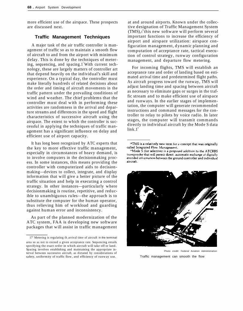
Photo credit: Federal Aviation Administration
Traffic management can smooth the flow

Ch. 4—Techno/ogy ● 6 9
Other components of TMS will contribute tomore efficient traffic management in other ways.Runway configuration management, a softwareprogram that has been under development at Chi-cago O’Hare since 1980, will assist controllers inestablishing the most efficient combination of ar-rival and departure runways for given conditionsof weather and demand. Departure flow meter-ing will help assure an appropriate blend of take-offs and landings and will feed aircraft out of theterminal area and into en route airspace.
FAA plans do not call for implementation ofTMS all at once, nor at all airports. The compo-nents are being developed separately and will betested and put in place as ready and where needed.The overall timetable is contingent on the devel-opment and installation of new computers andsector suites in terminal area control centers andon the development of companion software pack-ages for the en route ATC system—the AdvancedEn Route Automation (AERA) program. Full im-plementation of TMS, AERA, and related tech-nological changes will not occur until 1995 orlater.
TMS and AERA are tied together because FAA’slong-term response to air traffic growth involvesa general application of the flow management con-cept so as to provide strategic and tactical plan-ning, continuous performance monitoring, andflexible and adaptive exercise of control for theairspace as a whole. For example, en route meter-ing—which is a feature of AERA-will contrib-ute to efficient runway use by treating all arrivalsalong all routes as a single traffic pattern and ad-justing in-trail separation so as to achieve a steady
rate of delivery into the terminal area. The pres-ent method of flow management, which uses uni-form, preestablished in-trail separation, can re-sult in inefficient runway utilization (surges andgaps in the traffic flow) because it cannot adaptreadily when flow along arrival routes does notexactly match the nominal rate used as the basisfor selecting in-trail spacing.
The capacity benefits of TMS are difficult toestimate on a systemwide basis. The anticipatedbenefits are highly specific to conditions at the air-port site and particular patterns of demand. Fur-ther, it is not always possible to distinguish be-tween the benefits of TMS and those that wouldresult from other planned improvements in theATC system. Estimates published by FAA as partof an analysis of overall benefits and costs of theNational Airspace System Plan (NAS Plan) sug-gest that the benefits arising from improved traf-fic management and flow planning in terminalareas could be fuel savings on the order of 0.75to 1.25 percent. FAA calculates the value of thesesavings to be between $165 million and $280 mil-lion per year (1982 dollars) for the period 1993-2005. Of these savings, about 60 percent wouldaccrue to air carriers, with the remainder aboutequally distributed between business and privategeneral aviation.20
The FAA report does not provide a projectedcost for TMS alone, but lumps these costs withthose of AERA and other airport and airspaceprograms in the NAS Plan (see table 14). The total
Table 14.-Summary of NAS Plan Benefits and Costs (billions, 1982 dollars)
20-year totals Present (discounted) valuesa
Benefits costs Net Benefits costs Net

70 Airport System Development
costs are estimated to be $12 billion ($4 billionto aviation users and $8 billion to FAA) over thenext 20 years; the associated 20-year benefits arecalculated to be $24.7 billion to users, primarilyin fuel savings attributable to AERA and $24.3billion to FAA in operating cost savings. (All esti-mates in 1982 dollars. )
Supporting Technologies
In addition to programs aimed specifically atreducing delay and increasing the throughput ofmajor airports, FAA is pursuing other technologi-cal developments that will either facilitate theATC process or provide greater assurance ofsafety. Three particularly important developmentsof this sort are the Mode S data link, the CockpitDisplay of Terminal Information (CDTI), and theTraffic Alert and Collision Avoidance System(TCAS). These technologies will not, by them-selves, provide relief to the problems of conges-tion and delay in terminal areas, but they couldmake possible other technological improvementsor procedural changes to improve the flow oftraffic.21
The addition of Mode S to the present ATCRBStransponder has perhaps the most far-reaching im-plications for air traffic control. Mode S will allowthe air traffic controller to interrogate aircraft in-dividually and will make possible direct and selec-tive two-way digital communication between airand ground. Mode S thus will form the basis forthe more automated forms of air traffic controlenvisioned in the TMS and AERA programs.Equally important, Mode S will open up a new,high-capacity channel of communication that willprovide more complete and rapid exchange of in-formation and greatly reduce controller and air-crew workload by relieving them of the time-consuming process of transmitting, receiving, andacknowledging messages by voice radio. A thirdbenefit of Mode S is that it can enhance the sur-veillance function by reducing interference amongtransponder replies of aircraft operating close to-gether in terminal airspace.
An important potential application of the ModeS data link is that it could be used to improve the— — . —
“See Airport and Air Traffic Control System, op. cit., for moredetailed discussion of these technologies.
quantity and quality of information available inthe cockpit by providing a display of traffic inthe surrounding airspace. This display, CDTI, hasbeen under development for several years and hasbeen recommended by pilots and ATC experts asa valuable new tool to enhance safety and to aidmaneuver in terminal airspace. The CDTI, byshowing the location and path of nearby aircraft,could give the pilot an overall view of the trafficpattern and could provide an additional sourceof information under conditions of reduced visi-bility.
The CDTI is not envisioned as a substitute forground-based air traffic control nor as the basisfor independent maneuver to avoid collision orto assure safe separation. Rather, it is intendedas a supplemental display that will allow the pilotto “read” the air traffic pattern and to cooperatemore effectively and confidently with the ground-based controller in congested airspace. FAA, incooperation with the National Aeronautics andSpace Administration (NASA), is currently ex-ploring roles for a CDTI. The focus of this effortis to develop CDTI system requirements and todetermine the compatibility of these requirementswith Mode S and TCAS data sources.
The overriding concern in seeking ways to in-crease airport throughput and runway acceptancerates is maintaining safe separation among air-craft. Basic separation assurance is provided intwo ways: by application of the “see-and-avoid”principle in Visual Flight Rules (VFR) and by ATCprocedures and ground-based surveillance in In-strument Flight Rules (IFR). Pilots and others con-cerned with aviation safety have long advocatedadditional assurance in the form of an airborne(i.e., ground-independent) collision avoidancesystem. The system currently proposed by F&l—Traffic Alert and Collision Avoidance System—isan independent airborne device designed to useATCRBS (or Mode S) transponder informationfor generating a warning to the pilot that an ap-proaching aircraft is a threat and that evasive ma-neuver may be called for.
TCAS is in the development stage at presentand may not be ready for operational use untilthe late 1980s. The availability of TCAS, or anequivalent system of airborne collision avoidance,

Ch. 4—Techno/ogy . 71
will be an important factor in the decision toadopt revised procedures for increasing the effi-ciency of airspace use. Without assurance that safeseparation can be maintained and that there is a
backup to ground-based air traffic control, nei-ther airspace users nor FAA are likely to have theconfidence to proceed with revision of presentlongitudinal and horizontal separation standards.
AIRSPACE USE PROCEDURES
Procedures governing the use of terminal air-space and airport runways, which are designedprimarily to assure safety, sometimes slow ordisrupt the flow of traffic. In general, these pro-cedures consist of rules and standards pertainingto the permissible distances between aircraft invarious weather conditions and approach pat-terns. Actually, there are two sets of procedures:one for use in Visual Meteorological Conditions(VMC) and another, more stringent, set for usein Instrument Meteorological Conditions (IMC).Instrument Flight Rules —which are largely deter-mined by available navigation, communication,and surveillance technology—often cause delaysat busy airports because of the increased separa-tion standards and special safeguards that mustbe applied in restricted visibility.
There is a widely held, but not unanimous,view among airspace users that revisions of theexisting instrument flight procedures are practicaland that they would be warranted in the interestof reducing delay. While these revisions are some-times spoken of as capacity improvements, theywould not in most cases actually increase the ca-pacity of airports. Instead, they would allow ex-isting capacity to be used more fully or withgreater efficiency and would bring the through-put attainable under IMC closer to that whichprevails under VMC.
In response to urging from airspace users, FAAinstituted a comprehensive examination of air-space use procedures in October 1981. This ef-fort, known as the National Airspace Review(NAR) is a 42-month joint undertaking by FAAand the aviation industry “to identify and imple-ment changes which will promote greater effi-ciency for all airspace users and simplify [theATC] system. Additionally, the NAR will matchairspace allocations and air traffic procedures totechnological improvements and fuel efficiency
programs.”2 2 The portion of NAR concerned spe-cifically with terminal area ATC procedures wascompleted in July 1984.
Many of the procedural changes sought byairspace users and under study by FAA in NARwere also examined by a special aviation indus-try task force convened at the request of FAAunder the auspices of the Airport Operators Coun-cil International. The task force report, issued inSeptember 1982, strongly urged FAA to revisepresent airspace use procedures, especially thosepertaining to the use of multiple runways underInstrument Meteorological Conditions.23
Reduced Lateral Separation
Several of the proposed revisions would per-mit changes in the standards for lateral separa-tion of aircraft under instrument flight conditions.The present standards often severely restrictthroughput because they preclude use of all theavailable runways when visibility is reduced. Ifthe airport could continue to operate these run-ways, the disparity between IMC and VMC ac-ceptance rates could be substantially narrowed.The following are the major capacity-relatedchanges under consideration.
Converging Runways
Converging runways are those whose extendedcenterlines meet at a point beyond the runwaysthemselves. Simultaneous approaches to con-verging runways are presently authorized onlyduring VMC. The proposed procedure would ex-
25-420 0 - 84 _ 6

— —-
72 . Airport System Development
tend this authorization to IMC in certain circum-stances. The major problem to be overcome inusing converging runways under instrument con-ditions is development of procedures to assureseparation in the event of a blunder by one of theaircraft during the approach or in case both air-craft must execute a missed approach at the sametime. These procedures, in turn, depend on theavailability of improved surveillance radar, MLSto provide missed approach guidance, and per-haps automated aids for the controller to coordi-nate simultaneous approaches to two runways.
In time, it maybe possible to extend these pro-cedures to the case of intersecting runways-thosewhose surfaces actually cross at some point. Inaddition to the problems of blunder protectionand separation assurance during missed approaches,this configuration poses the risk of collision be-tween two aircraft on the ground, and there mustbe adequate safeguards that aircraft on both run-ways can stop or turn off before reaching the in-tersection. Because of the inherent safety prob-lems, most observers are skeptical about thefeasibility of using this type of runway layout forinstrument operations.
Dependent Parallel Runways
At present, instrument approaches maybe con-ducted on parallel runways that are as close as3000 ft apart so long as a diagonal separation of2 nautical miles (nmi) is maintained between ad-jacent aircraft. For parallel runways separated by2,500 ft, the diagonal spacing requirement is 2.5nmi. In addition, aircraft must be separated by1,000 ft vertically or 3 nmi horizontally as theyturn onto their parallel approach paths. Theserunways are termed dependent because the ap-proaches to each must be coordinated to main-tain the prescribed diagonal spacing. Hence, theoperational rate attainable on either is constrainedby the movement of aircraft on the other.
FAA studies suggest that the diagonal spacingrequirements for IFR operation on dependent par-allel runways could be reduced. For runwaysseparated by 2,500 ft, the standard could be re-duced from the present 2.5 nmi to 2 nmi with cur-rent technology and no other changes in existing
procedures. 24 Reducing the spacing requirementsfor approaches to parallel runways less than 2,500ft apart requires: 1) that the pilot be able to con-firm that he is, in fact, on approach to the properrunway since radar surveillance would no longerbe sufficient; and 2) that wake vortices from air-craft approaching one runway do not interferewith operations on the other. Because of wakevortex, current procedures require that aircraftapproaches to closely spaced parallel runways(less than 2,500 ft apart) be treated as approachesto a single runway and separated accordingly.
An operational solution to the wake vortexproblem on closely spaced parallel runways en-tails that the following additional conditions bemet:
●
●
●
●
●
there must be a steady crosswind to diminishthe effects of wake vortex, but the windvelocity must be less than maximum cross-wind limitation;small aircraft that are vulnerable to wakevortices must use the upwind runway of theclosely spaced pair;the threshold of the upwind runway mustbe displaced from that of the downwindrunway;the upwind runway must have a high-angleglide slope to allow for a steeper descent byvulnerable aircraft so that they can remainabove, and hence avoid, wake vortices; andwind monitors must be set up along the ap-proach path to ascertain that conditionsare favorable for the dissipation of wakevortices.
Satisfying these requirements may be difficultat airports that do not have runways with suitablystaggered thresholds and a sufficiently large num-ber of aircraft that can approach at a steeper thannormal glide slope to avoid wake turbulence. Inaddition, there are operational difficulties thatmay limit the applicability or the capacity benefitsof this procedure. First, the wake vortex gener-ated by a heavy aircraft carrying out a missed

Ch. 4—Techno/ogy . 73
approach could interfere with operations on theother runway. One possible solution would be torequire that both the leading and trailing aircraftexecute missed approaches along diverging pathswhenever the leading heavy aircraft misses the ap-proach. Second, interference from departurescould limit capacity gains since it may be neces-sary to retain present longitudinal separationstandards between heavy aircraft departing onone runway and small aircraft landing on theother in order to avoid wake turbulence. Finally,as the distance between parallel approaches is re-duced, there will be a need for more accurate sur-veillance to verify that aircraft are on approachto the proper runway. The radar now in use,which has a 5-milliradian accuracy and a 4-secondupdate rate, is probably not adequate for this pur-pose and may have to be replaced with new ra-dar capable of l-milliradian accuracy and 1-second update .25 Such radar performance has beenachieved in the Precision Approach Radar systemformerly installed at some airports but now de-commissioned. Military radar also has this capa-bility but would have to be adapted and testedbefore use in civil aviation.
Independent Parallel Runways
Independent instrument approaches to paral-lel runways separated by at least 4,300 ft arepresently authorized under the following condi-tions: 1) when aircraft are turned onto the ap-proach path, they must be separated vertically byat least 1,000 ft or laterally by 3 nmi from air-craft turning on approach to the other runway;and 2) a “No Transgression Zone, ” at least 2,000ft wide, must be maintained between the ap-proaches, with a separate controller assigned tomonitor this zone. A study by FAA indicates that,as with dependent parallel runways, reducinglateral spacing for independent parallel runwaysfrom 4,300 to 3000 ft would require installationof more accurate radar but no other changes incurrent procedures. 26
251bid.‘b Ibid.
Triple Parallel Runways
Demand at some of the busier airports, suchas O’Hare, Atlanta, Dallas/Fort Worth, Pitts-burgh, and Detroit, sometimes exceeds the capac-ity of the runway system in IMC, and additionof a third approach stream would be desirable.Current ATC procedures allow approaches to tri-ple parallel runways only during VMC. Revisionof separation standards to permit their use dur-ing IMC would significantly expand the time thatmaximum airfield capacity is available at thesefew very busy airports.
While the requirements for three parallel ap-proaches are similar to those for two parallel ap-proaches, the addition of a third runway com-plicates the approach procedures and limits possiblegains in capacity utilization. To be most effective,at least the outside pair of approaches should beindependent from each other, although both maybe dependent on the middle runway. If all threeparallel runways were dependent, there would beonly a minor increase in throughput compared tothat attainable with two dependent runways.Also, since a blunder on one of the outside ap-proaches could affect more than one other air-craft, establishment of triple independent paral-lel approaches necessitates two “No TransgressionZones, ” with a separate controller assigned tomonitor each. Because the l, 000-ft vertical separa-tion rule for aircraft turning onto parallel ap-proach paths still apply, final approach courses,particularly for the center runway, would belonger–thereby diminishing somewhat the through-put gain attainable with the triple parallel con-figuration.
A few airports have runway layouts that allowa converging approach to be added to two existingparallel approaches. This third approach is usedduring VMC, but in IMC the converging runwaymust be closed because separation between air-craft executing missed approaches cannot beassured visually.
The requirements for three approaches, one ofwhich is converging, are similar to those for twoconverging approaches. However, establishing thethird converging approach for use with a paral-lel pair involves additional safeguards because ablunder by an aircraft on one of the outside ap-

preaches affects more than one other aircraft. Themissed approach path for the converging runwaymust be coordinated with those of the other tworunways—a procedure that is quite complex andcannot be implemented without further researchand evaluation. In particular, FAA is studyingwhether MLS will be required to provide non-conflicting missed approach paths .27
Reduced Longitudinal Separationon Final Approach
Current procedures require longitudinal (in-trail) separation of 3 nmi between aircraft con-ducting instrument approaches to the same run-way In VMC, in-trail separations of 2.5 nmi

Ch. 4—Technology ● 7 5
For those airports where runway occupancy timeaverages so seconds or less, FAA studies indicatethat minimum in-trail separation of 2.5 nmi couldbe allowed in circumstances where wake vortexand ATC workload permit. Flight tests conductedby the U.S. Air Force have demonstrated the fea-sibility of 2.5-mile separation for military use.However, safety standards for commercial oper-ations are different than those for military oper-ations, and analysis of radar accuracy and updaterates, controller and pilot response times, and air-craft performance characteristics will be neededto determine whether 2.5-mile separation duringIMC is safe for civil aviation. Since there is a di-rect relationship between in-trail separation andthroughput, this procedural change would be avery effective method to reduce delay under in-strument flight conditions.
Present ATC procedures specify that the nom-inal longitudinal separation standards for VMCor IMC be adjusted to compensate for the possi-ble effects of wake turbulence. These separationstandards, shown in figure 9, are based on a three-way classification of aircraft according to grosstakeoff weight and attempt to account for thewake-turbulence characteristics of aircraft andtheir vulnerability to wake vortex encounters:
●
●
●
heavy ah-craft—maximum gross takeoffweight (GTW) in excess of 300,000 lb,large aircraft—maximum GTW between12,500 and 300,000 lb, andsmall aircraft—maximum GTW less than12,500 lb.
Definition of aircraft categories based on GTWalone is not an accurate index of of wake vortexgeneration for all aircraft, notably those aircraftwhose GTW is slightly over 300,000 lb such asthe DC-8 and B-767. As the number of B-767 air-craft in the fleet grows and as the re-engining pro-gram for DC-8S proceeds, aircraft whose GTWis roughly 300,000 lb will become an increasinglylarge proportion of the commercial aircraft fleet.If these aircraft continue to be classified as “heavy,”greater arrival separations will be required, withadverse effects on capacity and delay.
If aircraft were classified on the basis of moreprecise analytical or empirical data concerningtheir specific aerodynamic and wake-vortex char-acteristics, it might be possible to reduce the in-trail separation rules for some types. As a mini-mum, the use of approach weight rather thanmaximum GTW as the basis for separation cri-teria could be considered. To be even more pre-
Figure 9.—Arrival and Departure Separations
utical MilesInstrument Flight Rules
Lead
s 3 3 3
L 4 3 3
H 6 5 4
Minimum Departure Separations—SecondsVisual Flight Rules* Instrument Flight Rules
K —., I [ I f l - . - : l I I [
1 s I 35 I 45 [ 50
H I 120 I 120 I 90
KEY: S = Small, L = Large, H = Heavy (see text.)

76 ● Airport System Development
cise, wingspan, approach speed, and engine andflap configurations should also be taken into ac-count. A recommendation to this effect was madein the report of the Industry Task Force on Air-port Capacity Improvement and Delay Reductionand is now under consideration by FAA.31
Separate Short Runways forSmall Aircraft
The current practice in air traffic control is toorganize aircraft on approach according to timeof arrival, not type of aircraft. So long as the traf-fic mix is reasonably uniform, this practice hasa minor effect on throughput. At many airports,however, small aircraft represent a significant por-tion of traffic. To avoid wake turbulence gener-ated by the heavy and large classes of transports,these small aircraft are required to follow in trailat distances of 4 to 6 nmi from the larger aircraft.Since many of these small aircraft operate at slowspeeds, safety requires that larger and faster air-craft be spaced more than 3 nmi behind so thatthe leading small aircraft are not overtaken on ap-proach. One way to overcome these operationalpenalties would be to segregate small general avia-tion and some commuter aircraft into a separatetraffic stream using a different (short) runway. Atsome airports such a runway is already availablebut not usable for instrument approaches because
of inadequate instrumentation; at others, newrunways would have to be built and equippedwith MLS.
There is some disadvantage to separate shortrunways in that they do not provide as muchoperational flexibility as a full-length additionalair carrier runway. However, the separate shortrunway can be built at a fraction of the cost ofan air carrier runway, and runway siting prob-lems as well as local environmental issues maybe easier to resolve.
Ideally, the separate short runways for smallaircraft should be parallel to and operate inde-pendently from the main runway used by largeair carrier traffic. A short runway that is not par-allel to the main runway would not be availablefor use in IMC unless revised procedures for con-verging instrument approaches are also imple-mented; but even so, dependency on the mainrunway would limit the throughput gain becauseof the need to coordinate the two traffic streams.If the procedures described above to reduce spac-ing requirements for independent and dependentparallel approaches prove feasible, the siting ofthese short secondary runways could becomeeasier. Another development that would facilitatesiting of short runways and broaden the appli-cability of the concept would be installation ofMLS to allow curved approaches and steeper glideslopes by small aircraft, not only to alleviate waketurbulence problems but also to achieve a greaterrate of runway use.
WEATHER AND ATMOSPHERIC EFFECTS
Perhaps the single greatest technological need scribed above is a better method to detect or toin relieving delay at airports, aside from improved predict the occurrence of wake turbulence.radar to monitor aircraft more closely spaced interminal airspace, is development of techniques Beyond this, improvement in the ability to pre-to improve the detection and prediction of weather diet weather and atmospheric phenomena couldand atmospheric effects. Weather-related technol- lead to general reductions in delay. Present tech-ogies are typically viewed as safety improvements nology does not always permit sufficiently ac-rather than capacity improvements, but there are curate prediction of the time and magnitude ofsignificant exceptions—notably methods to pro- adverse weather conditions, making it necessarytect from wake vortices. Current aircraft arrival to increase safety margins and thereby reduceand departure separations are predicated in large throughput. The ability to foresee disruptions duepart on avoidance of wake vortices, and the key to weather would permit planning to compensateto many of the revised approach procedures de- fer the impacts on traffic flow.
Ch. 4—Technology 77
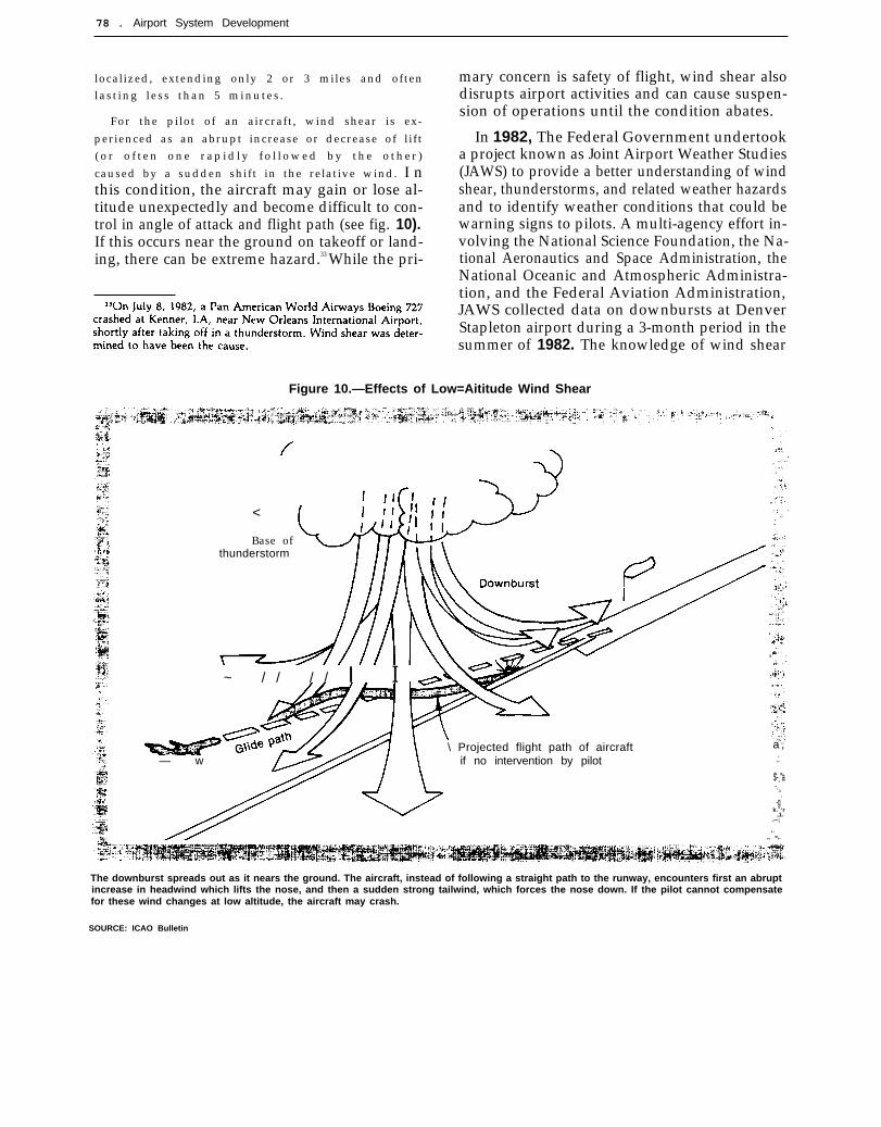
Wake Vortex
Wake vortex is an aerodynamic disturbancethat originates at the wingtips and trails in cork-screw fashion behind the aircraft. Since the strengthof the turbulence increases with lift, the strongestvortices occur behind heavy aircraft. These vor-tices spread downward and outward in the wakeof the aircraft and may persist along the flight pathfor as long as 2 or 3 minutes in still air. Whenthe aircraft is within 300 ft of the ground, the vor-tices can bounce off terrain and rise back towardthe flight path, creating even more disturbance.Wake turbulence can be of such strength andduration that it poses a hazard to following air-craft (especially smaller aircraft), and present pro-cedures require separation of 3 to 6 nmi depend-ing on the size of the leading and following aircraftand the movement of the airmass.32
Alternatives to the present procedural methodof avoiding wake turbulence are being soughtboth in the interest of safety and for the capacitybenefits that could be realized through closer spac-ing of aircraft in the approach zone. Two avenuesare being taken. FAA has concentrated on devel-opment of techniques to detect wake vortex andto predict its movement and persistence. NASAhas focused on aerodynamic research to providebetter understanding of the mechanics and causesof wake vortex and to develop designs to alleviateit at the source. NASA research indicates that cer-tain combinations of flaps, spoilers, and protru-sions on wing surfaces can reduce turbulence orcause it to dissipate more quickly. Unfortunately,many of these techniques also tend to increasenoise and reduce energy efficiency. Work is con-tinuing on ways to minimize wake vortex at anacceptable price in terms of noise and fuel con-sumption, but no ready solution is in sight. Thisis an important area of research and developmentsince the alternative—wake vortex detection andavoidance—has not been perfected to the pointthat pilots have confidence in its reliability.
FAA has sought to develop equipment and aconcept of operation that provide real-time vortex
32J. N. Barrer, “Operational Concepts for Reducing Vortex Spac-ings on Closely Spaced Parallel IFR Approaches, ” The MITRE Corp.,WP-81W520, September 1981.
sensing capability and to devise a predictivealgorithm that will warn pilots and controllers.An experimental device, known as Vortex Advi-sory System (VAS), was installed and tested atO’Hare in 1978. VAS is made up of wind sensorsmounted on towers along the approach path, acentral computer to process wind data and pre-dict the strength and movement of wake tur-bulence, and a display to alert the controller whena hazardous condition exists. VAS has not yetproven operationally acceptable, and FAA plansfurther development and test.
The disadvantage of VAS is that it does notdetect wake vortices; it only measures wind direc-tion and velocity, from which an inference canbe made about the presence and strength of waketurbulence. This deficiency is particularly evidentfurther out on the approach path (beyond themiddle marker) and in crosswind conditionswhere turbulence on one approach path maymigrate to a parallel approach. To overcome theselimitations, FAA is also investigating other tech-nological approaches such as short-wave radar,lasers, and infrared devices that could provide bet-ter long-range sensing and wider coverage.
No practical solution is now in view, and itseems likely that procedural methods to avoidwake turbulence will continue to be employed.So long as wake vortices cannot be reliably de-tected and predicted, the present separation stand-ards (perhaps with some modification to accountfor the aerodynamic characteristics of specifictypes of aircraft) will remain in force and precludeany throughput gains that might be achievedthrough reduced in-trail spacing.
Wind Shear
Wind shear is any sudden change in wind veloc-ity or direction. It may be associated with warmand cold fronts, low-level jet streams, or moun-tainous terrain. One of the most dangerous typesof wind shear is a downward surge of air strik-ing the ground and spreading out in all directions.This kind of wind shear is often associated withthunderstorms, but it may occur in other weatherconditions. These downdrafts, called microbursts,are difficult to predict because they are small and
78 . Airport System Development
localized, extending only 2 or 3 miles and oftenl a s t i n g l e s s t h a n 5 m i n u t e s .
For the pilot of an aircraft , wind shear is ex-
perienced as an abrupt increase or decrease of l ift( o r o f t e n o n e r a p i d l y f o l l o w e d b y t h e o t h e r )
caused by a sudden shift in the relative wind. I nthis condition, the aircraft may gain or lose al-titude unexpectedly and become difficult to con-trol in angle of attack and flight path (see fig. 10).If this occurs near the ground on takeoff or land-ing, there can be extreme hazard.33 While the pri-
mary concern is safety of flight, wind shear alsodisrupts airport activities and can cause suspen-sion of operations until the condition abates.
In 1982, The Federal Government undertooka project known as Joint Airport Weather Studies(JAWS) to provide a better understanding of windshear, thunderstorms, and related weather hazardsand to identify weather conditions that could bewarning signs to pilots. A multi-agency effort in-volving the National Science Foundation, the Na-tional Aeronautics and Space Administration, theNational Oceanic and Atmospheric Administra-tion, and the Federal Aviation Administration,JAWS collected data on downbursts at DenverStapleton airport during a 3-month period in thesummer of 1982. The knowledge of wind shear
Figure 10.—Effects of Low=Aititude Wind Shear
<
Base ofthunderstorm
~ / / / / I I
\ Projected flight path of aircraft~..
— wa ,
if no intervention by pilot .:. .$-=”a-.
“.-g
k. ‘r,1.
.-~;
,<
,, =,.
The downburst spreads out as it nears the ground. The aircraft, instead of following a straight path to the runway, encounters first an abruptincrease in headwind which lifts the nose, and then a sudden strong tailwind, which forces the nose down. If the pilot cannot compensatefor these wind changes at low altitude, the aircraft may crash.
SOURCE: ICAO Bulletin

Ch. 4—Technology ● 7 9
gained through JAWS will contribute to the LowLevel Wind Shear Alert System (LLWSAS) whichprovides the air traffic control tower with infor-mation on wind conditions near the runway.LLWSAS consists of an array of anemometers thatread wind velocity and direction around the air-port and signal the sudden changes that indicatewind shear. LLWSAS is now installed at 60 air-ports, and FAA plans to deploy 50 more by 1985.
Over the longer term, FAA is developing othersystems intended to provide better and moretimely weather information at airports, both toimprove safety and to help in traffic management.The Automated Weather Observing System(AWOS) will gather weather data from urtrnannedsensors, automatically formulate weather reports,and distribute them to airport control towers.AWOS will also broadcast this information topilots as voice synthesized messages over VHFradio. Implementation of the system, scheduledfor the period 1983-90, began with a l-yeardemonstration program in June 1983, when 21
units were put into operation at towered and non-towered airports in various locations. Full deploy-
m e n t a t 7 4 5 a i r p o r t s i s s c h e d u l e d t o b e g i n i n1 9 8 6 .34 A similar system, Joint Automated Weather
“Several GA user groups have argued that the AWOS timetablecould be accelerated by a year or more and have asked FAA to recon-sider the deployment schedule.
Observation System (JAWOS), is planned for in-stallation at some medium and large hub airports.JAWOS will automatically gather local weatherdata and distribute it to other air traffic controlfacilities and to the National Weather Service.
In cooperation with the Department of Defenseand the National Oceanic and Atmospheric Ad-ministration, FAA is also developing a next gen-eration nationwide weather network based onpulsed Doppler radar (NEXRAD). This networkwill provide more accurate information on pre-cipitation, reflectivity, wind velocity, and tur-bulence. NEXRAD will probably not provide theminute-to-minute observations needed to detectsmall localized downbursts that produce windshear, nor will it be able to detect wind shear inthe absence of precipitation. Still, NEXRAD willgreatly improve the quality and comprehensive-ness of the weather information available to airtraffic controllers and will be a significant aid inmanaging traffic to compensate for adverse weatherconditions. A total procurement of 160 units isplanned, with the last scheduled to be in place andthe system fully operational by 1992.
NOISE CONTROL AND ABATEMENT
Aircraft noise, especially the noise of jet air-craft, is one of the greatest barriers to airport uti-lization and expansion, and it is the most com-mon subject of complaint by airport neighbors.The areas of severest noise impact are just beyondthe ends of runways, but noise levels can be unac-ceptably high elsewhere along approach and de-parture paths where aircraft are close to theground. In legal actions brought by airport neigh-bors, the courts have generally found that the air-port operator is responsible for injury due to re-duced property value or nuisance and have awardeddamages to property owners and others affectedby noise.
There are two ways to reduce noise. One is toquiet the aircraft themselves, notably the engines,
and FAA has imposed progressively stricter noisestandards for aircraft in FAR 36 and FAR 91E.35
As a result, new aircraft entering service are muchquieter than earlier models, and some older air-craft have been equipped with new, quieter en-gines. While research is continuing on aircraftnoise, airframe and engine manufacturers tend tothe view that large-scale and cost-effective ad-vances in the technology of noise suppression willbe increasingly difficult to find.
35FAR part 36 defines noise requirements for certification of newaircraft and engines. FAR Part 91 Subpart E sets the timetable forcompliance and calls for retirement or retrofit of aircraft (both foreignand domestic) that do not comply with FAR Part 36 by 1985. Toprotect air service to small communities, FAR Part 91 Subpart Eallows three additional years (until 1988) for twin-engine aircraftwith 100 or fewer seats to achieve compliance.

80 ● Airport System Development
The other approach has been to impose opera-tional restrictions on airports—principally in theform of limits on the hours of use, frequency offlights, and the approach and departure routesthat may be taken. Airport operators and airlineshave resisted these measures since they reduce thecapacity of the airport overall or at peak timesand because noise abatement flight proceduresoften result in lengthier, less fuel-efficient pathsto and from the airport. Two studies of airportcapacity published recently have stressed the needto lessen some of these restrictions in the interestof increasing airport capacity and making moreefficient utilization of aircraft.3b 37
The discussion that follows addresses first pro-spective improvements in aircraft technology thatmight lessen noise, and then procedural solutionsto alleviate the noise problem.
Aircraft Noise
Aircraft noise has two components: enginenoise produced by moving engine parts and byair flow through the engine, and airframe noisecaused by the passage of air over aircraft surfaces.In early jet aircraft, the engine was the predomi-nant noise source. Advances in engine technol-ogy over the past 20 years have reduced enginenoise to the point where the engine and the air-frame are now about equal contributors to air-craft noise on landing. The engine is still the ma-jor noise source on takeoff.
Engine Noise
The principal sources of noise in a jet engineare: 1) the fan, 2) the compressor and turbine, and3) the exhaust. The relative importance of thesesources varies somewhat with the design of theengine and the operating regime, but exhaust noiseis generally the greatest of the three.
Efforts to reduce fan noise have centered onaltering the design of the fan blades and incor-porating sound absorbing material in the fan caseand the inlet and discharge ducts. Typically, this
36 Report and Recommendations of the Airport Access Tskk Force(Washington, DC: Civil Aeronautics Board, March 1983).
37 Report of the Industry Task Force on Airport Capacity Improve-
ment and Delay Reduction, op. cit.
sound absorption is accomplished by a liner ofporous material backed by cavities to trap sound.The newer aircraft engines now in service incor-porate these design concepts, but further, smallnoise reductions may still be achieved.
Compressor and turbine noise are generated in-side the engine by the compression, heating, andexpansion of the air passing through. Methods forreducing compressor and turbine noise have in-cluded redesign of compressor parts and turbineblades to modify their sound characteristics, anduse of sound absorbing material. Since the abilityto alter the design or configuration of the com-pressor or turbine is limited by mechanical andaerodynamic considerations and engine load re-quirements, it is expected that the principal methodto attain further reductions in compressor and tur-bine noise will be acoustic treatment in the intakeducts. Research is now aimed at development ofimproved acoustic material capable of withstand-ing the hot and cold environment of the com-pressor and turbine, and at reducing the cost ofthese noise suppression treatments.
Exhaust noise results from the turbulent mix-ing of hot, high-speed exhaust gases with the am-bient air. The way to reduce this noise is throughtechniques that lower the temperature and veloc-ity differential between the exhaust and the out-side air, but without loss of engine efficiency andthrust. In the early, pure turbojet engines, all ofthe intake air was passed through the hot sectionof the engine, from which it exited at high veloc-ity. These engines were very noisy. A later de-velopment diverted some of the air from the com-pressor around the combustion chamber andturbine and merged it with the exhaust stream—thus shielding the high-velocity exhaust with acooler, slower moving sheath of air from the com-pressor. These low bypass ratio engines were moreefficient and proved, on average, to be about 8decibels (dB) quieter than pure turbojets.38 Enginesintroduced in the 1970s made use of an evenhigher bypass ratio to achieve both greater fuelefficiency and a further 8- to 10-dB reduction ofnoise .39
38 The bypass ratio is the amount of air diverted around the com-bustor relative to that which passes through it.
39 For reference, a change of 3 dB is just perceptible to the humanear. A reduction of about 10 dB is perceived as halving the amoyanceof a sound source.

Ch. 4—Technology ● 8 1— .
Engine manufacturers are continuing to exploretechniques such as high-pressure turbines, exhaustdiffusers, and improved internal cooling methods–principally to increase engine efficiency but alsofor their potential to reduce noise. They are alsoevaluating internal flow mixers to combine low-velocity bypass air with higher velocity engineflow to produce an exhaust stream with less tur-bulence and a more uniform exit velocity. Theseefforts are yielding diminishing returns since fur-ther noise reduction involves very tightly coupledtradeoffs with fuel efficiency, production tech-niques, and maintenance costs. Attainment ofnoise levels significantly lower than those of FARPart 36 appears to be very difficult without a sac-rifice of fuel efficiency or a large cost penalty.
Airframe Noise
Airframe noise stems primarily from turbulentair flow past the undercarriage, leading and trail-ing edges of high-lift devices, aircraft cavities, andprojections from the aircraft surface. For an air-craft in flight, these noises intermingle and are notusually distinguishable as to source. The principalmethods available to reduce aerodynamic noiseare wing design, high lift systems, and aircraftstreamlining.
Recent exploratory development in aircraftwing design has included supercritical airfoil sec-tions and winglets. Aircraft using these wing de-sign features are currently being flight tested. Fun-damentally, the supercritical airfoil and wingletswould reduce drag and provide additional lift, butthey also serve to reduce aerodynamic noise some-what. Drag is exhibited as turbulence in the wakeof aircraft, and turbulence produces noise. Fur-ther, insofar as reduced drag and increased lift per-mit the aircraft to be operated at lower power set-tings on takeoff and landing, these aerodynamicimprovements might provide a secondary bene-fit of reduced engine noise.
Advanced high-lift systems make use of two-segment trailing edge flaps and a variable camberon the leading edge of the wing. High-lift devicesof this sort are currently used on Short Takeoffand Landing (STOL) aircraft such as the deHavillandDHC 7. They have also been incorporated in somelarge transport aircraft. The 747 and later model
727 aircraft have triple-slotted flaps, and the 767has both variable camber leading-edge flaps anddouble-slotted trailing edge flaps. These systemsdo not necessarily produce quieter aircraft; in fact,they may be noisier. However, high-lift devicespermit steeper approach and takeoff paths, therebyreducing the size and severity of the aircraft noisefootprint on the ground and leading—in effect—toless aircraft noise overall.
Techniques to streamline aircraft include place-ment of fairings around extended landing gear andother projections from the aircraft surface andenclosure of wing and body cavities. Such featuresare intended primarily to improve the aerody-namic performance of the aircraft, but they couldalso lessen aerodynamic noise. Another streamlin-ing technique involves strategic placement of theengines at locations where the airframe can actas a shield for engine noise. There are criticaltradeoffs between engine placement and aircraftperformance and safety that need to be treatedcarefully. There is also a need for additional re-search to improve the understanding of how theengines and airframe interact in the productionand suppression of noise.
Many of the techniques described above mightlessen aerodynamic noise, but the overall reduc-tion would probably be rather small. There is awidely held view among aircraft designers thatthe newest aircraft are close to the practical lowerlimit of aerodynamic noise and that further re-ductions will be technically difficult, prohibitivelycostly, and perhaps disadvantageous for otheraspects of aircraft performance. While some ofthese techniques will be pursued and might be in-corporated in future aircraft, the general opinionis that there are no aerodynamic solutions thatwill lead to large-scale reductions in aircraft noise.
Aircraft Operating Procedures
In addition to technological measures to reducenoise at the source, there is the the proceduralsolution of operating aircraft in a way that alle-viates the effect on noise-sensitive areas. Manysuch measures have already been adopted—somelocally, some more generally—and work is con-tinuing to improve these procedures, to devise
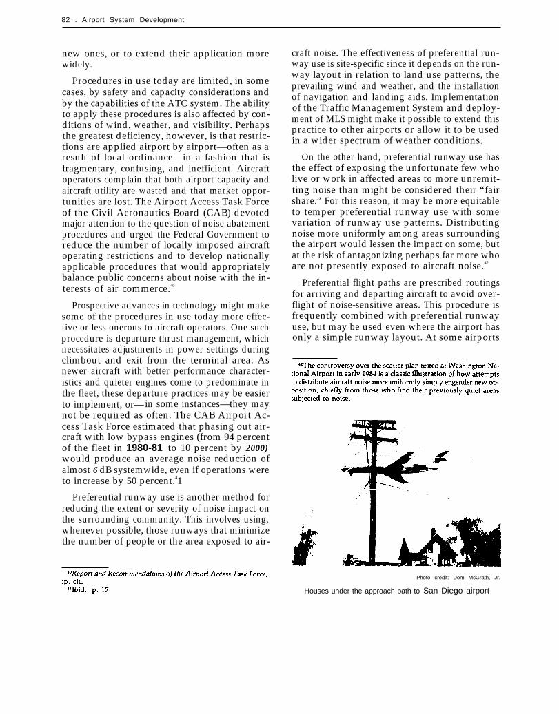
82 . Airport System Development
new ones, or to extend their application morewidely.
Procedures in use today are limited, in somecases, by safety and capacity considerations andby the capabilities of the ATC system. The abilityto apply these procedures is also affected by con-ditions of wind, weather, and visibility. Perhapsthe greatest deficiency, however, is that restric-tions are applied airport by airport—often as aresult of local ordinance—in a fashion that isfragmentary, confusing, and inefficient. Aircraftoperators complain that both airport capacity andaircraft utility are wasted and that market oppor-tunities are lost. The Airport Access Task Forceof the Civil Aeronautics Board (CAB) devotedmajor attention to the question of noise abatementprocedures and urged the Federal Government toreduce the number of locally imposed aircraftoperating restrictions and to develop nationallyapplicable procedures that would appropriatelybalance public concerns about noise with the in-terests of air commerce.40
Prospective advances in technology might makesome of the procedures in use today more effec-tive or less onerous to aircraft operators. One suchprocedure is departure thrust management, whichnecessitates adjustments in power settings duringclimbout and exit from the terminal area. Asnewer aircraft with better performance character-istics and quieter engines come to predominate inthe fleet, these departure practices may be easierto implement, or—in some instances—they maynot be required as often. The CAB Airport Ac-cess Task Force estimated that phasing out air-craft with low bypass engines (from 94 percentof the fleet in 1980-81 to 10 percent by 2000)would produce an average noise reduction ofalmost 6 dB systemwide, even if operations wereto increase by 50 percent.41
Preferential runway use is another method forreducing the extent or severity of noise impact onthe surrounding community. This involves using,whenever possible, those runways that minimizethe number of people or the area exposed to air-
craft noise. The effectiveness of preferential run-way use is site-specific since it depends on the run-way layout in relation to land use patterns, theprevailing wind and weather, and the installationof navigation and landing aids. Implementationof the Traffic Management System and deploy-ment of MLS might make it possible to extend thispractice to other airports or allow it to be usedin a wider spectrum of weather conditions.
On the other hand, preferential runway use hasthe effect of exposing the unfortunate few wholive or work in affected areas to more unremit-ting noise than might be considered their “fairshare.” For this reason, it may be more equitableto temper preferential runway use with somevariation of runway use patterns. Distributingnoise more uniformly among areas surroundingthe airport would lessen the impact on some, butat the risk of antagonizing perhaps far more whoare not presently exposed to aircraft noise.42
Preferential flight paths are prescribed routingsfor arriving and departing aircraft to avoid over-flight of noise-sensitive areas. This procedure isfrequently combined with preferential runwayuse, but may be used even where the airport hasonly a simple runway layout. At some airports
Photo credit: Dom McGrath, Jr.
Houses under the approach path to San Diego airport
Ch. 4—Technology ● 8 3
the use of preferential flight paths is limited bythe availability or capability of the installed land-ing and navigation aids. It is expected that MLSwill enhance the ability to use noise-avoidanceflight paths since it provides more precise and flex-ible approach guidance with a wider range of cov-erage than the existing ILS. MLS would permitmultiple final approach paths, including curvedapproaches. The ability to fly curved approachpaths will enable aircraft to avoid noise-sensitiveareas in IMC much as they do now in VMC andwill aid in the reduction of noise levels for air-
ports with noise-sensitive land uses located underthe straight-in approach path. MLS would alsoallow some aircraft to fly steeper approach paths,which—by keeping aircraft higher as they passover development around the airport-will reducethe area of high noise impact. In FAA studies ofthe application of MLS to specific sites, it wasfound that the use of curved and segmented IMCapproaches made possible by installation of MLSat airports such as La Guardia, Minneapolis, SanFrancisco, Seattle, and Washington Nationalcould lead to significant noise reductions.
AIRPORT SURFACE UTILIZATION
An airport is an interconnected set of physicalfacilities and components. For it to function effi-ciently, the capacities of each of these elementsmust be matched. Relief of a bottleneck in onepart of the airport will not have the desired ef-fect on overall throughput unless other parts arecapable of absorbing a greater influx of traffic.Indeed, a common experience is that enlargementof one part of the airport complex simply shiftsthe delay elsewhere, to the next most constrain-ing element.
Nowhere is this more evident than on the air-port surface. Measures to augment runway capac-ity or to increase the flow of traffic through theairspace may be of little practical benefit unlessaircraft are able to move expeditiously on and offrunways and to and from the terminal building.It is on airport taxiways and aprons that aircraftare closest together and that their speed is lowest.If the movement of aircraft on the airport surfaceis constrained by runway and taxiway design andlayout, by operational procedures, or by poor vis-ibility, the effect ripples throughout the airportand airspace, and delays accumulate.
This section examines three types of technol-ogy deployed on the airport surface: surveillanceand control systems, taxiway design and lighting,and equipment used at parking aprons and gates.In general, new airport surface utilization tech-nologies will not lead to major increases of air-side capacity, which is largely determined byavailable runways and airspace use procedures.The primary capacity benefits are indirect—in-
creased safety, especially during inclement weather,and relief of operational impediments to makingefficient use of the airside.
Surveillance and Control
Surveillance and control of aircraft movementon the airport surface is accomplished largely byvisual means. In darkness or fog—and even ingood visibility at large, complex airports-AirportSurface Detection Equipment (ASDE) is used byair traffic controllers to augment and confirm in-formation obtained from visual surveillance of theairport surface. Used primarily at high activityairports, ASDE allows controllers to locate andmonitor the movement of aircraft and groundequipment on runways, taxiways, and apron areas.
The existing equipment, designated ASDE-2,utilizes tube technology, which presents reliabilityand maintenance problems. In addition, utility ofASDE-2 is limited by display resolution, bright-ness, airport map definition, and poor weatherpenetration capability. The last is particularly sig-nificant under conditions of precipitation or fog,when the system is needed the most. Under theseconditions, visual surveillance is virtually impos-sible, and ASDE is the controller’s primary meansto obtain the necessary information.
A new system utilizing solid state technologyis programmed for deployment by 1986-89. Thissystem, ASDE-3, is expected to increase reliabilityand reduce system maintenance, in addition to im-proving display resolution and weather penetra-

. .
84 Airport System Development
tion. More accurate information on the specificlocation and movement of aircraft and groundequipment on the airport surface provided byASDE-3 might allow reductions in safety-dictatedseparation of aircraft and promote more efficientutilization of runways and taxiways. Ultimately,small gains in airfield capacity could result.
Research and development on more advancedsystems will be needed since even ASDE-3 can-not identify aircraft and surface vehicles under allweather conditions or be used by the controllerto guide them to their destinations. At present,the capability of navigation systems to help air-craft land in very low visibility (Category IIICoperations) exceeds that of surveillance and con-trol systems to guide them after they are on theairport surface.
The Tower Automated Ground SurveillanceSystem (TAGS) is a display enhancement intendedfor use in conjunction with ASDE at major air-ports. The ASDE-3 search radar provides a mapof the airport and the location of aircraft on theairport surface, which are shown graphically onthe ASDE display. TAGS will provide, for trans-ponder-equipped aircraft, a flight identificationlabel alongside the position indicator on the ASDEdisplay. Since TAGS operates by receiving asignal transmitted directly by aircraft equipment,the system would be virtually immune to weather.Presentation of flight identity by TAGS wouldalso improve ground control capability in goodvisibility. TAGS is presently in the exploratoryphase of development and probably will not beready for deployment until the 1990s.
Taxiways
The design and layout of taxiways, particularlythose that provide egress from runways, have animportant effect on runway occupancy time(ROT) .43 The placement of exit taxiways, wherelanding aircraft turn off the runways, and theangle at which these taxiways intersect the run-ways can be crucial. Poorly placed exit taxiways
prolong runway occupancy by forcing incomingaircraft to taxi at low speed for some distancebefore clearing the runway. Taxiways that leavethe runway at right angles force the aircraft tocome almost to a complete stop before turning.Since the runway occupancy rule (with a few ex-ceptions in VMC) does not allow an approachingaircraft to cross the runway threshold while thepreceding aircraft remains on the runway, longerrunway occupancy either forces the air traffic con-troller to increase arrival spacing or causes someapproaching aircraft to execute a go-around—both of which are disruptive of throughput.
At some airports, relocating taxiways so thataircraft with shorter stopping distances can leavethe runway sooner would lower ROT by as muchas 20 to 30 percent. At others, providing a drift-off area alongside the runway or redesigning taxi-ways so that they diverge from the runway grad-ually and allow aircraft to turn off at higher speeds(i.e., sooner after landing) would have much thesame effect. However, translating reduced ROTinto a corresponding throughput gain is notstraightforward since it depends on whether therunway layout, the airspace geometry, and theATC procedures will permit closer arrival spac-ing to take advantage of the shorter runway oc-cupancy. Still, it is an avenue to be explored, andamong the recommendations of the Industry TaskForce on Airport Capacity Increase and Delay Re-duction were several that urged FAA and airportoperators to adopt measures that would assistfaster exit from runways.44 One of these was toadopt procedures and rules that would increasethe motivation of pilots to use specified rapid exitsand improve the coordination between controllersand pilots in minimizing ROT.
Marking and lighting of taxiways can be as im-portant as their design and physical layout in ex-pediting ground movement of aircraft. For run-way exits to be used to their full potential, pilotsmust be able to detect their location and identifythe one they are to use with ample Ieadtime. Thisis especially critical at night and during periodsof poor visibility. A taxiway marking and lightingsystem that conveys the necessary information to
44Report of the Industry~ Task Force on Airport Capacity Improve-ment and Delay Reduction, op. cit., pp. 11-14.

Ch. 4—Technology ● 8 5
pilots in a clearly understandable fashion willpromote more efficient utilization of airfieldpavements.
Research and development are in progress onseveral aspects of marking and lighting. For exittaxiways, the major efforts are to improve thelighting pattern and the configuration, spacing,and orientation of components in a way that pro-motes ready identification of the exit and providesvisual guidance for safe and prompt transitionfrom the runway to the taxiway. Among the areasunder study are improved lighting and signing fortaxiway intersections, traffic control signals andlighting systems for ground guidance, and meth-ods for controlling lighting patterns and intensityfrom the tower. Development is also proceedingon new lighting techniques such as lights that uselow voltage electricity, light-emitting diodes, andelectroluminescent components to relieve some ofthe deficiencies of present lighting, which pilotscharacterize as “the blueberry pie maze. ”
To optimize the use of airport pavements andto make proper decisions related to safety, pilotsand controllers must have accurate and up-to-date
information on surface conditions that affect air-craft ground movement and stopping character-istics. Perhaps the most noticeable changes inthese characteristics are aircraft braking and stop-ping distance on wet or icy pavement, which areimportant not only from a safety standpoint butalso because of the effect on capacity.
One major effort is to devise pavement designsand surface treatments that will improve traction.Research is also being conducted on means to pro-vide information that will allow pilots and con-trollers to predict aircraft stopping capability andskid risk more accurately under various runwaysurface conditions. Items such as pavement sen-sors that continuously monitor pavement condi-tion and coefficients of friction are being exam-ined. Attention is also directed at developmentof better methods to convey this information tothe pilot and, ideally, to provide braking guidanceor warning of specific hazardous conditions andlocations. The primary concern is safety, but bet-ter information about pavement condition andaircraft performance when traction is reducedwould also yield a capacity benefit in that a moreaccurate delineation of safety limits might make
Photo credit’ Federal Aviation Administration
Night life at Chicago O’Hare

86 . Airport System Development— . — —
it possible to relax some of the present conserv-ative rules governing aircraft movement on thesurface in slippery conditions.
Apron and Gate Facilities
Opportunities to relieve airport surface conges-tion extend up to the parking spaces at the gates.Aircraft docking is typically accomplished by aramp agent with flashlights and hand signalsguiding the flight crew for proper parking of theaircraft and assuring that the wing tips have safeclearance from buildings, ground equipment, andother aircraft. New optical, electrical, electronic,and mechanical devices are being developed toprovide flight crews with positive visual guidancethat will permit more rapid and accurate dock-ing. This technology will allow apron space to beused more efficiently and help prevent the delaysthat arise when aircraft must be repositioned inorder to mate with fixed ground support systemsand passenger loading bridges.
While needs and procedures vary by airline andby airport, the aircraft servicing functions com-monly performed at an airport include fueling,engine start, galley and cabin service, electricalground power, towing, passenger stair or loadingbridge operation, and handling of baggage, mail,and cargo. In addition, various routine or specialaircraft maintenance functions are conducted.
Several technological advances offer reductionsin servicing time and cost. At some airports,ground power is now being provided by fixed sys-tems mounted on the passenger loading bridge orin underground pits. Similarly, fixed pneumaticsystems are being developed to provide groundpower and aircraft engine start. These installationsease the congestion caused by mobile units clus-tered around aircraft on the ramp and provide fora more efficient servicing operation. Auxiliarypower units now provided on most newer aircraftalleviate congestion by replacing ground equip-ment needed for electric service, air start, and air-conditioning. These self-contained units also assistin quick turnaround, thereby reducing gate oc-cupancy time. Special pallets and handling equip-ment provide for efficient transfer and loading of
bags and cargo. While use of this technology savestime at the gate, the loading and unloading of thepallets themselves can sometimes be time-con-suming due to mechanical problems and align-ment difficulties.
These improvements in technology help easesurface congestion in two ways, Those that speedturnaround lessen gate delays and enhance through-put. Those that reduce the apron space neededfor service vehicles and equipment allow more air-craft to be parked in a given area, thereby directlyincreasing apron capacity and helping to ease air-port surface congestion in general.
Terminal Facilities and Services
The airport terminal-the building itself and thepaved areas surrounding it on the airside and thelandside—is the zone of transition for passengers,providing the link between surface and air trans-portation. Design and operation of the terminalhave an influence on both airside capacity andground access and on overall throughput of theairport complex. This basic relationship, illus-trated in figure 11, dictates that the design of theterminal complex must reconcile the requirementsof three operational areas:
●
●
●
airside—where aircraft are serviced andpassengers board,terminal building—the collection point con-taining facilities for passenger processing andservices during transfer between airside andlandside, andlandside—the area accommodating groundtransportation (roadways, parking areas,etc.).
Basically, the terminal and associated landsidefacilities are long-term installations with relativelystable patterns of use. They are largely independ-ent of the specialized aircraft and airline passengerprocessing functions that occur on the airside. Incontrast, the airside is characterized by short-term, impermanent use which is closely tied tochanging aircraft technology with a useful life ofabout 10 to 15 years. The essence of airport ter-minal design is to strike an appropriate balance

Ch. 4—Techno/ogy . 87
AIRPORT PARKING
Spec!al Report 159, 1975”
between these somewhat contradictory require-ments.45
The principal effect of the terminal on the air-side is through the design of aprons and gates,which determines the number of aircraft that canbe accommodated at one time and the turnaroundtime for passenger boarding and aircraft servic-ing. As seen in the previous section, gate andapron operations can also have a wider—thoughnot major—effect on airside throughput. The im-
pacts of terminal design usually do not extendbeyond the apron and gate area, and terminalbuilding characteristics have scant influence onthe design of other airside components such astaxiways and runways.
Overall, the influence of the terminal on thefunctional requirements and performance of air-side facilities is relatively small compared with theinverse effect that the airside exerts on the ter-minal.4b The primary purpose of the terminal isto transfer passengers and their baggage betweensurface and air transportation with minimumtime, confusion, and inconvenience. The func-
4’Horn and Orman, op. cit.
25-420 0 - 84 - 7

gg . Airport System Development
tional requirements and choice of design for a ter-minal complex must take into account the pas-senger and baggage flows resulting from aircraftsize, traffic mix, schedules of operation, and typeof service provided (origin-destination or connect-ing flights). As a design task, this involves the in-tegration of three major parts of the terminal: air-side gates, passenger collection and service areas,and landside access and egress. Since these partsare highly interactive, it is important that theseparation between them be kept to a minimumand that traffic flow smoothly among the parts.
This would be a fairly straightforward taskwere it not for the need to design the airside in-terface so that it can be adapted to accommodatecontinually changing aircraft technology, airlineservice patterns, and traffic volumes. At somelarge hubs, the steadily increasing size of aircraftand their fixed-point servicing requirements, whencoupled with growing passenger and automobiletraffic, have led to terminal complexes of a sizethat imposes inconvenience and delay on passen-gers. In response, airport designers have beenforced to add an intermediate transportationmode within the terminal itself (moving sidewalks,transport buses, fixed rail systems, and other suchpeople movers) to aid passengers in transferringbetween the airside and the landside.47
The discussion that follows touches first on gen-eral questions of terminal building design and thenon technology of specific features that might beimproved to facilitate passenger movement or toreduce passenger inconvenience and delay. Itshould be recognized that these aspects of designand operation will have little, if any, effect on air-side capacity and throughput even though theymight lead to substantial reductions in the over-all trip time for air travel. It should also be rec-ognized that such matters have been of little in-terest to FAA or to policymakers in the FederalGovernment. They are, of course, keenly impor-tant to airport operators and—to a lesser extent—airlines because they constitute investment needsthat must be balanced against airside capacity ex-pansion in the overall program of capital improve-
“M. Brink and D. Maddison, “Identification and Measurementof Capacity and Levels of Service of Landside Elements of the Air-port,” in Airport Landside Capacity, op. cit.
ment for airports. Recent estimates indicate thatover half of the large hub airports are experienc-ing congestion and delay within terminal buildingsand that over 30 large and medium hubs are con-templating investments in terminal expansion orimprovement, with a total cost of $4 billion. 48 49
Terminal Building Design
Airport terminals can be grouped into four cat-egories according to their basic design concept:
●
●
●
●
centralized with finger piers—a common hallwith branching corridors leading to aircraftgates;centralized with satellites—a central con-course surrounded by small, separate clustersof gates and waiting areas, each connectedto the concourse by walkways or peoplemovers;linear or gate arrival—usually semicircularbuildings with ground access on one side andaircraft gates on the other, designed so as tominimize walking distance through the ter-minal; andtransporter— a compact passenger facilitywith buses or special vehicles used for trans-port to a remote aircraft parking apron.
These concepts are embodied in pure form onlyat a few airports which have been built on entirelynew sites. At most airports the design of the ter-minal building has evolved and been modified inresponse to traffic growth and local conditions,giving rise to a hybrid that incorporates featuresof two or more of the basic concepts (fig. 12). Atairports with land available adjacent to the ex-isting facility, the design has tended to evolve intoa finger pier arrangement, sometimes with sepa-rate unit terminals for commuter airlines or groupsof new air carriers for whom there is not roomin the main terminal. At airports where the ter-minal has grown to the limits of available landarea, satellite terminals and remote hardstandparking have typically developed. Transporterand satellite terminal concepts utilizing people-

Ch. 4—Technology ● 8 9
[ I
I J
[ 1
ii)r0n.(ncm
1=

SW ● Airport System Development
moving equipment have been adopted at some air-
ports to enhance the attractiveness of the terminal
for passengers since they eliminate the extremewalking distances associated with long piers ex-tending from central terminals. The transporterconcept has the additional advantage of allow-ing a small terminal building, free of the con-straints imposed by aircraft parking gates.
At a new site, the choice of terminal design islargely dependent on the volume and type of traf-fic expected. Centralized terminals are best for air-ports with a high proportion of transferring pas-sengers, especially those changing from one airlineto another. The gate-arrival design works well fororigin-destination passengers and commuter air-lines since it shortens the transit from the curb-front to the aircraft gate. The unit terminal withpassenger transporters can handle peaks of traf-fic efficiently, but only if the traffic is made uplargely of origin-destination passengers. In the ex-pansion of existing terminals, these same con-siderations come into play, but the choice maybe constrained by the design of the existing struc-ture, the available land, and the on-airport roadnet.
Misestimation of traffic volume or the type ofservice to be provided can sometimes render evena well-conceived design inefficient or inappro-priate. Dallas-Fort Worth Airport, for example,was planned with the expectation that origin-destination traffic would predominate. Since air-line deregulation, the growth of hubbing—whichtypically requires passengers to change planes atthe airport—has thwarted the effectiveness andconvenience of the design. At O’Hare, the needto adapt the concourses for passenger securityscreening has created long and circuitous routesfor transferring passengers. Efforts to encouragegreater use of Dunes Airport for short and medi-um-length domestic flights have been hindered bythe design of the terminal since the need to gofrom apron to terminal and back again by mobilelounges greatly increases the time and inconven-ience of interline connection. Kennedy Airport,planned with separate terminals for major airlines,is well-suited for origin-destination passengers andfor transfers to flights on the same airline, but veryinconvenient for interlining domestic passengers
and those coming in on international flights andcontinuing to other U.S. destinations.
Clearly, no single design is best for all circum-stances. Traffic patterns, traffic volume and flowcharacteristics (e.g., peaking), the policies of in-dividual carriers using the airport, and local con-siderations (e.g., esthetics and civic pride) dictatedifferent choices from airport to airport and fromone time to another. The airport planner, whois required to anticipate conditions 10 to 15 yearsin the future, must often resort to guesswork.Even if the guess is right initially, conditionschange—as the above examples illustrate—and re-sult in a mismatch between terminal architectureand the traffic to be served. To guard against this,airport planners now tend to favor flexible designsthat can be expanded modularly or offer the op-portunity for low-cost, simple modification asfuture circumstances may demand.
Terminal Services
These precautions, of course, are of little helpin terminals that have already been built for onetype of traffic but forced to accommodate another,or where demand outstrips capacity. Many air-ports will continue to suffer from inappropriateor outdated designs that lead to congestion anddelay in passenger areas and diminish the over-all utility of the airport as a transportation hub.For such airports, an alternative to a new or ex-panded terminal as an avenue of relief from con-gestion is to correct specific features that causebottlenecks by applying improved technology thatwill compensate for design inadequacies. Someof these partial technological remedies are dis-cussed next.
Passenger Movers
To speed passenger movement through the ter-minal and to lessen the inconvenience of walk-ing long distances to board flights or to reachlandside exits, some airports have turned to pas-senger movers. so Several technologies are avail-able, covering a broad spectrum of cost. They in-
Ch. 4—Technology . 91
elude buses, mobile lounges, moving sidewalks,and automated guideway systems. The choice ofany of these involves a tradeoff between theirservice characteristics and cost (capital and oper-ating) against those of adding new gates or ter-minal wings. This tradeoff is very sensitive to therate of use, the specific vehicle chosen, and thecost of gate construction. Passenger movers tendto be more cost effective than gates if the rate ofuse is high. Variation in traffic load is also im-portant, and analysis indicates that passengermovers are best suited to serving those locationsand intraterrninal trips where there is a great fluc-tuation in demand. 5l
Buses and mobile lounges add to airside sur-face traffic; they are also labor-intensive andtherefore costly to operate. For these reasons, air-ports with finger piers or satellite terminals havesometimes opted for automated vehicles such asmoving sidewalks or guideway transit systems.Moving sidewalks are not an entirely satisfactoryoption. They are costly to operate and maintain,and their speed must be slow to allow passengersto board and descend safely. Thus, they provideonly a marginal decrease in passenger movementtime, although they greatly reduce the effort oflong passages through the terminal complex.There is some experimentation with acceleratingdevices and transition techniques that would per-mit greater line speeds and still afford comfortableand safe boarding and descent. If these experi-ments are successful, the utility of moving side-walks will be greatly increased.
For longer distances or where the volume oftraffic is large, automated guideway systems aresometimes practical. Several different types areavailable, varying principally in terms of propul-sion, vehicle size, and complexity of the guidewaynetwork and control system. Reliability and traincontrol system design were problems in the firstsystems installed at airports (Dallas-Fort Worth,for example), but the technology has improvedrapidly and now appears to give good service atairports such as Atlanta and Orlando. Capitalcosts of vehicles and guideway construction re-main high, and they are still difficult and expen-
51 R. De Neufville, Airport Systems Planning (London: Macmillan,1976); pp. 118 ff.
sive to maintain. The view of airport designersis that these systems are cost effective only at afew very large airports, and there is reluctanceto utilize this technology except as a last resort.
Ticketing
The ticket counter serves three major functions:ticket transactions, baggage check-in, and flightinformation. Of these, the most time-consumingare ticket transactions (which often include bag-gage check-in for the individual passenger). Tech-nologies to speed ticket counter operations or toeliminate them altogether are being explored, bothto reduce delays in the terminal and to cut air-line personnel costs. Computerized ticket systemsavailable today offer passengers advance reser-vations and sales, preassignment of seats, andautomatic tagging of baggage. They will probablybe used more widely by the major air carriers,some of whom may also offer them to small car-riers under a service contract. A companion de-velopment is the computerized aircraft manifestthat has been implemented by some airlines. Thesesystems typically produce aircraft load sheets,passenger manifests, and automatic telex reser-vations. They greatly reduce the administrativework at the counter and expedite airline dispatchfrom the gate.
Ticket dispensing machines similar to thoseused for banking are now in limited use by someairlines at a few locations and for selected routes.Improvement of these machines so that they canhandle a larger number of routes and fare struc-tures could promote wider use, with correspond-ing reduction in the amount of activity that mustbe conducted at the ticket counter. This technol-ogy could also be extended to sale of tickets offthe airport property. With the deregulation oftravel agencies, the range of services provided bythese firms has expanded, offering passengers analternative to purchasing tickets at the airport.Travel agents now account for more than 60 per-cent of airline ticket sales in the United States. Theentry of mass-marketing firms such as Sears andTicketron into the air travel field may further de-crease the need for ticketing at airport terminals,reducing airline personnel and equipment require-ments, and alleviating congestion at terminalticket counters.

.
92 . Airport System Development
Baggage Handling
The handling of baggage, especially baggageclaim at the end of a flight, is a common and=for passengers—particularly onerous form of de-lay in terminals. At most airports, baggage han-dling is the responsibility of the individual air car-riers, but some airports operate a consolidatedbaggage service—either with airport personnel oron a contract basis—in the interest of speedingthe process and reducing the cost. Reduction ofthe delays and passenger inconvenience associatedwith baggage handling has been approached inthree ways: more efficient procedures for check-in and claim, automated handling and sorting,and elimination of some baggage handling by en-couraging carry-on luggage.
One of the simplest and most widely appliedmethods to expedite baggage handling is curbsidecheck-in. This separates baggage handling fromother ticket counter and gate activities, therebydisencumbering those locations and allowing bag-gage to be consolidated and moved to aircraftmore directly. Another method is replacement ofthe baggage claim carrousel with loop conveyorbelts that allow passengers greater access to theirluggage without increasing the size of the claimarea.
Sorting baggage, moving it to and from theapron, and aircraft loading and unloading aretime-critical and labor-intensive operations. Tech-nologies to improve this process include high-speed conveyors to transport baggage between theterminal and the flight line, often used in conjunc-tion with pallets or containers that can be put onand taken off aircraft with labor-saving equip-ment. Computerized sorting equipment, capable
“ of distributing bags with machine-readable tags,has been installed at some airports. These devicesare not yet fully satisfactory since the encodingand reading of tags are time-consuming and some-what unreliable.
To handle peak loads, automated systems musthave a larger capacity because they are less flexi-ble than manual systems. Redundancy is a mustwith an automated system, which increases thecapital cost. As these automated systems improveand come into wider use, a further step is to in-stall self-service systems that allow passengers to
check and claim luggage either in the terminal,at the curbside, or at remote locations on or offthe airport property. While such a developmentwould be primarily a labor-saving measure by air-lines and airport operators, it might also speedtransit through the airport for many passengers.
The functional equivalent of automated, self-service baggage handling systems—and one thatmay be cheaper and more reliable—is expandedcapacity within the aircraft for carry-on luggage.With the advent of stronger and lighter materials,aircraft designers have been able to reconfigurecabins to provide larger and more secure storagespace on board. New aircraft universally containsuch overhead storage bins, and many airlineshave converted older aircraft to incorporate sim-ilar enclosed overhead storage. A further devel-opment might be provision of a common baggagespace either within the cabin or in a special mod-ule that could be transferred to the cargo bay.Passengers entering and leaving the aircraft wouldpass through this space and handle their ownbaggage.
Passenger Security Screening
To deter aircraft hijacking, the Federal Govern-ment has established regulations to ensure safepassage for the traveling public. These regula-tions, implemented in January 1973, require secu-rity screening of passengers and carry-on articles.Over the past decade, security screening has be-come an accepted fact of life for air travelers anda problem for airport designers and operatorssince the security checkpoints tend to disruptpassenger flow and—in some instances—forceremodeling of the terminal.
The equipment used today consists of X-raymachines with moving belts and magnetometersfor metal detection. This system, which replacedmanual search, significantly increased the capacityand capability of the screening process. The chiefdrawback of the existing equipment is that, whileeffective in detecting metal, it has limited capa-bility to detect explosives and volatile substances.
New technology for screening cargo and bag-gage is being investigated. The aim is both tospeed the screening process and to increase thethoroughness and reliability of detection. The new

Ch. 4—Technology ● 9 3
Photo credit’ Los Angeles Department of Airpofls
Customs and immigration: once gracious . . .
systems under development make use of improvedbomb and explosive sensing techniques such asvapor detection, bulk detection, and computerizedtomography.
Federal Inspection Service
The United States has 24 airports of foreignentry where Federal Inspection Service (FIS) forclearing passengers and cargo is provided byCustoms, Immigration, and Agriculture officials.Clearance procedures are rigid and time-consum-ing, and FIS processing has been a major causeof delay at high-volume ports of entry.
The U.S. Department of State is now issuingmachine-readable passports that may help ex-pedite FIS clearance. Additional procedures andtechnologies are being investigated to achievegreater capacity, reduced clearance time, andhigher agent productivity. Alternative proceduresand physical arrangement of facilities are the prin-cipal areas of concentration.
The system employed at most airports of en-try today is the Customs Accelerated PassengerInspection Service (CAPIS), which provides sep-arate immigration and customs checkpoints.CAPIS is highly time-consuming for passengersand labor-intensive to operate. A new system, re-ferred to as One Stop, combines immigration andcustoms functions at a single station. Althoughpromising, this system has not yet achieved itsexpected capacity in tests and demonstrations.Chicago O’Hare and Houston IntercontinentalAirport are experimenting with another approachthat uses a modified version of the standard Euro-pean system known as “Red-Green,” where trav-elers who do not have goods to declare are sep-arated from those who do, with only the latterpassing through a secondary inspection station.Also under study are hybrid systems that com-bine features of CAPIS, One-Stop, and the “Red-Green” concepts.
LANDSIDE ACCESS
Photo credit: U.S. Depatiment of Transportation
. . . now streamlined
It is a truism that nearly every airplane trip the figures vary among airports, it is generallybegins and ends with an automobile ride, and estimated that over 90 percent of all airline pas-there is no clearer manifestation of our depend- senger trips to and from airports are by privateence on the automobile than at the terminal curb- automobile or taxi. At medium and small airports,side and on the access roads to the airport. While the figure is probably close to 100 percent since

— .
● Airport System Development
these communities tend not to have well-devel-oped public transit providing a practical alterna-tive to the automobile.
A further indication of the symbiosis betweenthe airplane and the automobile is the emergenceand growth of the car rental industry. This busi-ness has its origin in the need for air travelers tohave transportation to and from airports in cit-ies away from home. While many car rental firmshave since branched out into other markets, thebulk of their business is still rentals to airlinepassengers, and revenues from this activity area major source of income for airport operators.
Not all trips to the airport are made by airlinepassengers or those who come to meet travelersor drop them off. For airport workers (account-ing for perhaps one-third of all access trips) andcalls by delivery vans, service representatives, andothers with business on the airport property (alsoabout one-third of all access trips), the automobilelikewise predominates. Some (especially airportworkers) come at times when public transit is notavailable or when service is infrequent, and theyhave almost no alternative but to drive to the air-port and park.
At many airports, automobile traffic is a prin-cipal source of landside congestion and delay. Ofthe 33 major airports surveyed by the IndustryTask Force on Airport Capacity Improvement andDelay Reduction, the most common problemareas were at the curbside (20 airports) and onairport circulation and access roads (11 airports) .52Similar findings were obtained in a survey of air-ports performed for this assessment. Of the 39large, medium, and small hubs and commuter air-ports sampled, 23 indicated present or anticipatedproblems with parking, curbfront circulation, on-airport roads, or access routes. A recent reviewof airport problems by FAA found that 23 of 41major metropolitan area airports are sufferingfrom capacity constraints imposed by landsidecongestion or lack of adequate access.53
Perhaps the best known example of the effectthat landside access can have on airport opera-
52 Report of the Industry Task Force on Airport Capacity Improve-ment and Delay Reduction, op. cit.
53 Metropolitan Area Assessment Report, op. cit.
tions is at Los Angeles International Airport(LAX). Because of limited capacity of airport cir-culation roads and the inability of the freewaysand city streets near the airport to absorb a greatervolume of automobile traffic, regional transpor-tation authorities imposed a capon aircraft oper-ations and annual passenger volume permitted atthe airport. Much of the impetus for the recentexpansion at LAX was to relieve this landside con-straint, and a large share of the $700 million mod-ernization program now nearing completion therewas expended to double-deck roads leading to andfrom the terminal and to remodel the terminalcomplex so as to segregate arriving and depart-ing automobile traffic .54
LAX is not an isolated example. Chicago O’Hareis proposing a $1 billion program of airport mod-ernization, a large share of which will be to “bringaging and congested terminal and roadway facil-ities into balance with underutilized airside capac-ity. “55 St. Louis spent $78 million of the total $273million in funds programmed through 1983 onhighways and airport frontage roads on or adja-cent to the airport property.sb The Port Author-ity of New York and New Jersey has launched a$1.5 billion modernization plan for the three NewYork airports. Important parts of this plan arenew roadways and local transportation to im-prove airport access and additional parking spacearound the terminals. s’
Only a few landside improvements and airportaccess projects are eligible for Federal aid fromthe Airport and Airway Trust Fund. The FederalHighway Administration (FHWA) and the UrbanMass Transportation Administration (UMTA)also provide funds for landside development, andthe airport operator or local airport authority con-tributes an important share through retained ear-nings and revenue bonds. Funding of landsideinvestments is a complex multijurisdictional ar-rangement with wide variation from airport to air-
54B. Sweetman, "The New LAX Prepares 1984, ” hteravia, JUIY
1983, pp. 724-725.55 J. Ott, “$1 Billion Upgrade Planned at O’Hare,” Aviation Week
& Space Technology, Aug. 8, 1983, pp. 35-36.“J. Ott, “Expansion Eases St. Louis Congestion,” Aviation Week
& Space Technology, May 23, 1983, pp. 35-36.“E. Kozicharow, “New York Port Authority Boosting Airport
Capacity,” Aviation Week & Space Technology, May 9, 1983, pp.33-34.
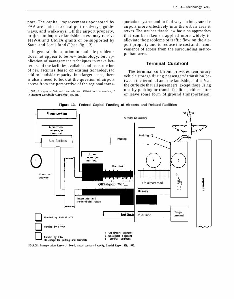
Ch. 4—Technology ● 9 5
port. The capital improvements sponsored byFAA are limited to on-airport roadways, guide-ways, and walkways. Off the airport property,projects to improve landside access may receiveFHWA and UMTA grants or be supported byState and local fundss8 (see fig. 13).
In general, the solution to landside problemsdoes not appear to be new technology, but ap-plication of management techniques to make bet-ter use of the facilities available and constructionof new facilities (based on existing technology) toadd to landside capacity. In a larger sense, thereis also a need to look at the question of airportaccess from the perspective of the regional trans-— —
58A. J. Negrette, “Airport Landside and Off-Airport Interaction, ”in Airport Landside Capacity, op. cit.
portation system and to find ways to integrate theairport more effectively into the urban area itserves. The sections that follow focus on approachesthat can be taken or applied more widely toalleviate the problems of traffic flow on the air-port property and to reduce the cost and incon-venience of access from the surrounding metro-politan area.
Terminal Curbfront
The terminal curbfront provides temporaryvehicle storage during passengers’ transition be-tween the terminal and the landside, and it is atthe curbside that all passengers, except those usingnearby parking or transit facilities, either enteror leave some form of ground transportation.
Figure 13.—Federal Capital Funding of Airports and Related Facilities
J Bus facilities I—
o1
Nonurbanbusway
Airport boundary
I Parking
i
Qff?akpop ‘Mxi “$,,+
Interstate andFederal-aid roads
b
❑ Funded by FHWA/UMTA
❑ Funded by FHWA
❑1—Off-ajrport segment
Funded by FAA 2—On-airport segment
(1) except for parking and terminals 3—Terminal segment
Parking (1)
1 #
1-Z
On-airport roaduJ—cm~ .5: E
Busway ~ ~
tCargo
truck lane terminal
SOURCE: Transportation Research Board, Airporf Landslde Capacity, Special Report 159, 1975.

● Airport System Development
Curbfront congestion is a particularly difficultproblem to solve because the facilities there areintimately tied to the design of the terminal build-ing and airport characteristics such as activitylevel (peak passenger volume), user characteris-tics (mode of transportation, mix of passengersand well-wishers, and number of bags), and vehi-cle characteristics (type, number of passengers,and dwell time at the curb). The most practicalapproaches are physical expansion or modifica-tion of facilities and procedural changes to im-prove passenger and vehicle flow.
The most common forms of physical improve-ment are additional curbfrontage, bypass lanes,multiple entry and exit points in the terminalbuilding, remote park and ride facilities, andpedestrian overpasses or underpasses. These im-provements are intended to increase the utiliza-tion of curbfrontage by vehicular traffic or, in thecase of park and ride, to reduce demand on thecurbfront by diverting passengers from privatecars to high-volume vehicles. Walkways to seg-regate foot and vehicular traffic promote pedes-trian safety and facilitate roadway traffic by elim-inating conflicts between pedestrians and vehicles.
In some cases, procedural changes—either aloneor in conjunction with low-cost physical modifica-tions such as signing or lane dividers—are an ef-fective alternative to expensive construction orremodeling of the curbfront. For example, park-ing restrictions combined with strict enforcementwill reduce curbside congestion and dwell time indischarging and boarding passengers. Short-termparking islands or reserved sections along thecurbfront, defined by roadway marking or sim-ple dividers, may segregate vehicles picking upor discharging passengers from those that musthandle baggage or enter the terminal for brief er-rands. Similarly, separation of private cars fromtaxis, buses, and limousines can diminish conflictsamong these kinds of traffic and improve the flowto and from the curbfront. An effective approachat some airports has been provision of bus serv-ice from remote parking to the terminal and reg-ulations to discourage bringing private automobilesto the terminal building. None of these measuresis a substitute for adequate curbside capacity, butthey can lead to more efficient use of the facil-
ities available and perhaps compensate for defi-ciencies in terminal and curbfront design.
Airport Ground Access
Aside from expansion or improvement of theroad network leading to the airport, most effortto facilitate airport ground access has focused onsubstitutes for the automobile. Bus or airlinelimousine service has proved workable in somecities, but patronage is generally low because ofthe infrequency of service or the inconvenienceof getting between origin or destination and a cen-trally located bus terminal. Helicopter shuttle be-tween the airport and city center has been tried;but it is expensive, unreliable because of weather,and objectionable to the community because ofnoise.
A solution that has been advocated by manyplanners is a rail rapid transit system, either oper-ated exclusively to and from the airport or as partof a regional network. Cleveland, for example,built a rapid transit extension to Hopkins Inter-national Airport in 1968; and the Washington,DC, Metro system includes a station near, but notat, the main terminal at National Airport. Pro-posals to provide such service-either by con-struction of a new line to the airport or by link-ing an existing line to the airport by a feederbus—have been advanced for several other cit-ies. 59
In part, this interest has been stimulated by ex-amples in foreign countries, which either have orare planning rail service to airports. Paris Charlesde Gaulle Airport has a rail station a little overa mile from the terminal with connection providedby shuttle bus. Amsterdam (Schiphol), Birming-ham, Dusseldorf, Frankfurt, Gatwick, Heathrow,Orly, Vienna, and Zurich already have rail sta-tions in or immediately adjacent to the airport ter-minal. Cologne and Munich 2 will have such serv-ice by 1985. Haneda Airport in Japan has a monorail
. . . . . . . . . .59 A survey by the U.S. Aviation lndustry Working Group in 1979
found that eight U.S. airports-AtIanta, Baltimore-Washington In-ternational, Kennedy, Los Angeles International, Oakland, Miami,Ontario (California), and San Francisco—were considering someform of rail link. Of these, Kennedy and Oakland have establishedsuch service, but in both cases it is by a bus connection with transitstation off the airport property.

Ch. 4—Technology ● 9 7
line from the center of Tokyo to the terminal,which brings passengers to within 300 ft of check-in counters. Toronto and Montreal (Dorval) inCanada have rail lines that are close by but notintegral with the terminal (a connecting bus ortaxi trip is needed to complete the link), and Mon-treal International (Mirabel) will soon have directservice from the airport to the downtown areawith 13 intermediate stops. Figure 14, a cutawaydrawing of the Zurich airport, illustrates the con-cept of the integrated airport-rail complex.
De Neufville points out that rail transit is nota universal solution to the airport access prob-lem. ’” In most major U.S. cities, there is not a re-gional rail network to be tied into the airport; and,without it, there is little prospect that an exclusiveline between downtown and the airport would beviable. Few passengers want to travel between theairport and the central business district, and evenfewer want to go during rush hour. Rail transit,with its fixed routes and corridor structure, doesnot serve well in the U.S. setting, where there iswide dispersion of origins and destinations for air-port passengers. The capital costs of such systemsare likely to be high, and it is doubtful that oper-ating expenses could be covered from the fare box,necessitating subsidy from the municipality or theairport. There may be public resistance to build-ing a system to serve airport users exclusivelywhen other parts of the metropolitan area couldprofit perhaps more from rail rapid transit serv-ice. Finally, the service characteristics of rail tran-sit do not lend themselves particularly well to air-port trips. Passengers encumbered by baggagefind rail transit inconvenient because there is nostorage space on trains and narrow aisles may bedifficult to negotiate with luggage in hand. If thereare intermediate stops—as there almost certainly
6 0 D e N e u f v i l l e , o p . c i t . , p . 7 .
would be if the rail line attempts to serve morethan a few who want to travel from city centerto the airport— the trip is prolonged, and trainsmay be crowded with passengers riding for otherpurposes.
These arguments do not necessarily deny thevalidity of foreign experience, but they raisedoubts about the viability of rail transit access toairports in this country —where we do not havethe population densities, the existing urban railnetwork, and the tradition of public transit thatare characteristic of Europe and Japan.
An alternative to rail transit, which accom-plishes the same purpose but with greater flex-ibility and somewhat lower cost, is the remoteairline terminal (fig. 15). This is a facility for proc-essing arriving and departing passengers at a siteoff the airport property and transferring them tothe terminal by group transportation. The off-airport terminal may include facilities for ticket-ing, baggage handling, and parking. Connectionwith the airport can be provided by public tran-sit, special airport bus, or helicopter shuttle. Thetechnology to implement this concept exists, andit has been tried in several cities.
The popularity of the remote terminal concepthas waned in recent years, largely because indirectcosts tend to offset the benefits. Trip origins anddestinations are becoming more and more scat-tered throughout the urban area, to the extent thattrips to and from the city center now account forless than a quarter of airport patronage. On theother hand, the increasingly tighter restrictionson airport terminal and landside expansion maymake this concept worth reexamining, particularlyif a way can be found to build and operate a net-work of small dispersed facilities adapted to theurban-suburban pattern of business and residencein major metropolitan areas.
APPLICATIONS OF TECHNOLOGY
In the search for solutions to capacity and de- ●
lay problems, the value of new technology is ●
typically measured by its ability to achieve one ●
or more of the following results: ●
TO AIRPORT PROBLEMS
increased capacity,higher efficiency (or throughput),greater safety,improved reliability,

98 ● Airport System Development

Ch. 4—Technology . 99
Figure 15.—Off-Site Passenger Terminal Concepts
Airporf terminal
Airport terminal
Exclusiveairport transport
Helicopteraccess
Off site terminal
ProcessingI
Airport terminal
#
Connectingpassengers only
SOURCE: Airpoti Landside Capacity, Transportation Research Board, Special Report 159, 1975.
● greater accuracy, tance, but it has little relationship to capacity and● lower cost, and delay unless—as is often the case with procedures• greater convenience. and rules—the requirement for safety precludes
some measure for increasing capacity or through-The first two are direct benefits; they constitute put. Thus, if some new method of assuring safety
relief of the problem of how to accommodate a is found and it also allows a subsequent changehigher level of demand. Safety is of prime impor- in procedures or utilization of airport facilities,
. Airport System Deve lopment
safety improvements may give rise to a second-ary capacity-related benefit. Reliability, accuracy,cost, and convenience are operational benefits.They are worth seeking in and of themselves, butthey have little direct relation to capacity exceptinsofar as they are attributes that lead to adop-tion of new technology or hasten its implemen-tation.
The description of airside, terminal, and land-side technologies presented in the first part of thischapter has touched on all of these prospectivebenefits. The emphasis has been on their poten-tial to relieve capacity and delay problems, butother attributes have been cited where they ap-pear relevant either to the future use of the tech-nology or to the choice of one form of technol-ogy over another.
To provide additional perspective on the valueof new and emerging technologies from the stand-point of capacity and efficiency, OTA surveyeda sample of 54 airports to determine the natureof the capacity and delay problems they now faceor expect to face within 10 years. The survey alsoexamined specific technological remedies thatmight be applied at each airport. The results ofthis survey, presented below, should not be in-terpreted as a prescription for planning and im-plementation of new technology at these airportsor for the airport system as a whole. Rather, thesurvey attempts to show the general extent towhich technology can improve the capabilities ofthe airport system and relieve congestion anddelay.
No attempt is made to quantify the systemwidecapacity increase or delay reduction that mightresult from application of new technology. Thesebenefits are highly dependent on the operationalconditions and physical characteristics of the in-dividual airport. Although certain airports maybe similar in some respects, there is little basis forconcluding that what works at one will necessarilybe of the same benefit to others. Thus, the tabula-tion of technological measures considered appro-priate to the airports surveyed should be viewedsimply as a general map of the forms of reliefavailable and their possible application to theproblems at representative airports.
Capacity and Delay Problems atSelected Airports
The airports surveyed consist primarily oflarge, medium, and small hubs, cross-categorizedby the predominant type of traffic—long-, medi-um-, and short-haul. Also included are a few com-muter service, reliever, and general aviation air-ports. The sample was not scientifically drawnand stratified to represent the airport system asa whole. In choosing these 54 airports, the intentwas to include as many types as possible so asto indicate the general problems that airports face,but the focus was on those where congestion anddelay tend to be greatest and have the more pro-nounced effect on air transportation—hence, thepredominance of large and medium hubs in thesample.
Another consideration governing the choice ofairports was other recent studies of airport capac-ity and delay. The report of the Industry TaskForce on Airport Capacity Improvement and De-lay Reduction contained a survey of 33 major air-ports; 19 of these are included in the OTA sam-ple. A study of capacity and delay performed byFAA in 1981, examined 19 large airports, of whichthe OTA ‘sample includes 13.61 Another FAAstudy described airport problems in 41 metro-politan areas.b2 The OTA sample includes airportsin 27 of these metropolitan areas, although notalways the major airport or all the airports thatFAA examined in their survey of the region. Byoverlapping the OTA sample with these otherstudies, the intent was to provide a cross-referenceto these reports and an indication of the similarityof findings.
Table 15 indicates the nature of the capacityand delay problems found in the OTA survey.For each of the airports, deficiencies and bot-tlenecks in the following areas were identified:
● airspace,● airfield,● taxiway,● apron,
Ch. 4—Techt?ology ● 101
●
●
●
●
●
●
●
gates,terminal building,parking,curbfront,on-airport roads,off-airport roads, andenvironment and noise.
Entries in the table indicate whether problemsor limitations exist now (E) or are expected in thefuture (F). The most severe problem area is iden-tified by a dagger. In all cases, this informationwas obtained from published sources (FAA reports,airport master plans, regional transportationstudies, and the like), supplemented with tele-phone interviews to confirm the findings or to re-solve differences among the source documents.
One of the highlights of this survey is thatairspace and airfield problems are widespread andaffect airports of all sizes. Of the 30 large andmedium hub airports, 23 reported existing orfuture airside limitations. So, too, did 17 of the24 smaller airports—an indication that this formof capacity limitation is not solely a function ofthe size of the airport. Gate and terminal prob-lems, not surprisingly, are confined almost ex-clusively to larger airports served by major aircarriers.
Perhaps the most striking result of the surveyis that landside congestion and delay at the curb-front, in parking areas, and on circulation andaccess roads are of equal rank with airside prob-lems at large and medium hub airports. The samenumber of airports —23 large and medium hubs—cited the landside and the airside as problem areas.For 10 of these airports, the airside is or will bethe most severe problem; for 8 it is the landside.This suggests that efforts to relieve congestion anddelay should not focus entirely on the airfield andairspace. Landside access is also a pressing con-
cern. The point is even stronger if the terminalbuilding is grouped with the landside. The airsideis the most severe problem area at 10 large andmedium airports, while at 15 the problem is innonaeronautical areas.
Prospective Technological Solutions
To complete the analysis, an assessment wasmade of the various forms of technology thatmight be applied to remedy problems at the sam-ple airports. Table 16 lists the results. The spe-cific problem areas cited earlier in table 15 havebeen combined into four general categories: air-side, airport terminal, surface access, and envi-ronment and noise. Listed under these headingsare technologies that have the potential to relieveor mitigate capacity and delay problems at the54 sample airports.
Table 16 does not constitute a comprehensivelist of all technologies that might be applied, onlyOTA’S estimate of those that offer the greatestpromise or would be the most practical to imple-ment. Identification of a technology as applica-ble to a given airport does not necessarily implythat FAA or the airport operator plans to imple-ment it, nor that capacity and delay problemswould thereby be “solved. ” In some cases, the ca-pacity gains provided by these technologies willbe small, or they may provide benefits only incertain weather conditions or for a small part ofthe day. Thus, table 16 should be interpretedsimply as a general indication of how the tech-nologies described here can be related to a set oftypical airports. For those familiar with conditionsat these particular airports, table 16 may also pro-vide insights on the relationships among variousmeasures to increase capacity or to reduce delayand on the dynamics of airside, terminal, andlandside interactions.

.
102 ● Airport System Development
1
I
I
I
I
I
I
I
I
I
I
I
L
I
I.1.l II I I
I I
1 ;-1I Iw LL L I l u l I I L L I U I Iu w W i l l
1 : ~
iii LL w - w
u L L L LU - w ’w
1 ~ 1
I II.1.l w
I
I
I
I
I
3=2’v.-
U U I L I
I LL I .L I
I I
II
I I
w i i u I I u
i iw -
iLIi”
I Lu’
Lu-
LL I LI.Lii u’I I Lu I
(.)n. .. x. 1 - - 1
sm3
0(.)
.-0L
i ia

Ch. 4—Technology ● 103
a
I
I-LLLi’
I
I
Ku-
1
I
I Lu-
1
-1 -1
u-w-
1
Lw“
I
I
I
L
I
I
Lw-
LLl
I I I I I I I
I I
I
I
I
I
I
I
I
I
I
+Lu
I
I
I
I
w
w
I
I
I
I
I
I
I
I
I
I
I
I
I
I
I
I
I
I
I
I
I
I
I
I
I
I
I
I
I
I i i I Iu-
‘ I L - 1 ILLl
I l l II
I
w
I
I
I
I
I
I u u I
I
u
I
I
I
I
I I l l II Lu
I I I l l I I Iw u LLl
u
I
Iiii
I
I I I I I
I
I
I I
Lu LLl w
I
I
I I
I I
I
I
w Lu
uii
I
uu-
1
I LLL-
I.Lu-
a0
c-0cal=
l.?
1 :-I :-w Lu
I I I Lu I I I I I I
+I LILl- Ill :’I l l I I
.I I I Iu
I
IA
+u-LLi- 1
kLL- 1 I i
w-I I I
. .. .o : :
s::, .. ... . x
1-. .. .. .. .
5a)-CzEi
N<
4
25-420 0 - 84 - 8
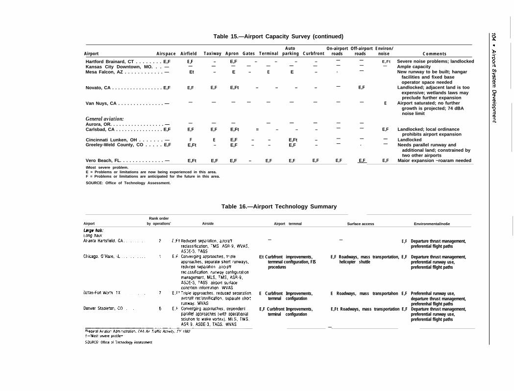
Table 15.—Airport Capacity Survey (continued)
Auto On-airport Off-airport Environ/Airport Airspace Air f ie ld Tax iway Apron Gates Termina l park ing Curbf ront roads roads noise C o m m e n t s
Hartford Brainard, CT . . . . . . . . E,FKansas City Downtown, MO. . . —Mesa Falcon, AZ . . . . . . . . . . . . —
E,F – E,F – – – –— — — — — — —Et – E – E E –
——.
—
—
——
——
E,F
— E,Ft—
Severe noise problems; landlockedAmple capacityNew runway to be built; hangar
facilities and fixed baseoperator space needed
Landlocked; adjacent land is tooexpensive; wetlands laws maypreclude further expansion
Airport saturated; no furthergrowth is projected; 74 dBAnoise limit
——
Novato, CA . . . . . . . . . . . . . . . . . E,F E,F E,F E,Ft – – – – E,F
Van Nuys, CA . . . . . . . . . . . . . . . — E— — — — — — — —
General aviation:Aurora, OR. . . . . . . . . . . . . . . . . . —Carlsbad, CA . . . . . . . . . . . . . . . . E,F
— — — — — —E,F E,F E,Ft = – – –
—— E,F
—
Landlocked; local ordinanceprohibits airport expansion
LandlockedNeeds parallel runway and
additional land; constrained bytwo other airports
Maior expansion ~roaram needed
Cincinnati Lunken, OH . . . . . . . —Greeley-Weld County, CO . . . . . E,F
F E E,F – – E,Ft –E,Ft – E,F – – E,F –
—. —
Vero Beach, FL. . . . . . . . . . . . . . — E,Ft E,F E,F – E,F E,F E,F E,F E,F——tMost severe problem.E = Problems or limitations are now being experienced in this area.F = Problems or limitations are anticipated for the future in this area.
SOURCE: Office of Technology Assessment.
Table 16.—Airport Technology Summary
Rank orderAirport by operatlonsa Airside Airport termmal Surface access Environmental/no6e
— — E,F Departure thrust management,preferential flight paths
Departure thrust management,preferential runway use,preferential fllght paths
Et Curbfront improvements, E,F Roadways, mass transportation, E,Ftermmal conftguratlon, FIS helicopter shuttleprocedures
E Curbfront Improvements, E Roadways, mass transportahon E,Ftermmal configuration
Preferenhal runway use,departure thrust management,preferenhal flight pathsDeparture thrust management,preferential runway use,preferential flight paths
E,F Curbfront Improvements, E,Ft Roadways, mass transportation E,Fterminal configuration
—.

Ch. 4—Technology . 105
I
I I I l l+L L L
u - u ”L
L u “
I IL
I u“L
U u ”
IL
u-L L
L u ”
L
u - u !+u
+U L L Ju w
+L u -
L U“ u“ L u
+-L L L
u- U “ w
+L
u“L
+ -W - u
+u
+ u - L L
L w - U“
Nco
m c T . r - -l i l m O m .. . -
xt - >
z c 1n
x1 -

106 ● Airport System Development
I I
I
I I
I
1
I
I
I
I I
I
L
U “ uu-LLl
L L
u“uu-
U“ w
I I I
I
I I I I
I
I
I
I
I II
I
L u-Ui
I
L
u“L
w“+uU J w
I II I I I
ms
I I
L L ; ~+LL iu -u ’ u ”
u-U“u U J U J L u
0 ?( n
U-J
I =1+++ +- +- +- ++-i-L
+
L L U L &L . +
U L L * I L
u - U - U ” U - L U U U “ u l u ” u u i t i t i ” m u ”
+uI-Ii L u
+ L .U J u
a l L n C u. - m m u
- JL
, +3 G.!