Embed Size (px)
Citation preview
Chapter 4
STUDIES ON POLY(VINYL CHLORIDE)/UNEAR LOW DENSITY
POLYETHYLENE BLENDS

STUDIES ON POLY{VINYL CHLORIDE)/LINEAR LOW DENSITY
POLYETHYLENE BLENDS
The widespread development of plastics and
plastic products all over the world has also brought it
with a huge problem. Plastics, today form a sizable
fraction of solid wastes, a large portion of which are
commodity plastics. Their lack of biodegradability 1S
generating new problems such as lack of landfill sites,
growing water and land surface litter etc. Recycling by
reprocessing of plastic waste 1S a solution to the major
problem created by the plastic consumer society. This
method of reutilisation of solid plastic waste is used as
a base for producing secondary products, lowering energy
costs, and reducing environmental pollution. Also :.he
increase in the price of polymeric raw materials is making
the recycling of consumer waste to secondary produc:.s
attractive. Polyethylene 1S a major component of the
plastic waste. Eighty per cent of the polyethylene waste
is con t amina t ed wi th other polymer s 1 ike pol ypropy 1 ene ,
1-3 polystyrene, poly(vinyl chloride) etc. However,
separating these polymers and then recycling them
individually, introduces an addition costly step in the
143

144
reprocessing route. Instead, reprocessing of the mixed
plastic waste is becoming more popular ln view of the
economic benefits.
Several researchers have studied the blends of
low density polyethylene (LDPE) with polystyrene (PS), 4.5"
high density polyethylene (HDPE) and polypropylene (pP).
Mikkonen et 2 al. studied the rheological, morpho-
logical and mechanical properties of the LDPE/plasticised
PVC blends. The PVC/PE blend is now utilised in several
applications like blister packaging, low halogen-low smoke
fire resistant electric cable sheathing etc. 6,7 Many of
the problems associated with recycling of mixed plastic
wastes are identifiable in the processing/reprocessing of
PVC/PE mixtures. Processing of the PVC/PE mixtures is not
likely to yield products with the expected mechanical
properties because of the poor adhesion of the phases due
d " "b'l' 8-10 to the thermo ynamlc lncompatl 1 lty. In literature,
various methods have been suggested for the reactive
compatibilisation of such immiscible blends for demanding
applications. The mechanical properties and the technical
performance of the immiscible blends would be more nearly
additive if the interfacial zone is strengthened. One way
to do this is to add interfacially active agents to the

145
immiscible " 8,10 m1xture. Thus the interfacial energy
between the immiscible phases is reduced ensuring a finer
dispersion upon mixing and higher stability against phase
" f "b"l" 11 separat1on. Most common types 0 compat1 1 1sers are
1. block, graft or random copolymers
2. co-solubilisers enhancing the interpenetration of
resin domains
3. co-reactors, catalysts enhancing chemical reaction
between the resins
4. modifications or additives enhancing specific
interactions.
In the present study an attempt 1S made to
modi ft _ the immiscible PVC/PE blend by various methods
listed above. The polyethylene selected for the study is
the newest member of the polyolefine family viz., linear
low density polyethylene (LLDPE), since it is fast
replacing low density polyethylene (LDPE) in many
applications. LLDPE has a greater degree of stiffness and
higher tensile strength than LDPE and also has a more
regular crystalline structure, higher melting point and a
better fracture resistance at low temperature. Coupled

146
with these attractive properties is the low pressure
manufacturing advantage of LLDPE compared to the high
pressure technique employed for LDPE. While LDPE is
manufactured by high pressure process in which polymeriza-
tion occurs by a radiCol mechanism, LLDPE 1S produced by
low pressure process with Ziegler-Natta or Phillips
catalysts in the presence of sufficient amounts of olefinic
comonomers. Although with respect to its density LLDPE is
a low density polyethylene from the point of view of its
structure it is a linear polyethylene containing short
. d h' 12 Sl e c a1ns.
...-_...l...-_~.J---~ __ I _JJ---,.--L
LDPE with branched chains LLDPE with short side chains

147
CHLORINATED POLYETHYLENE (CPE) AS A MODIFIER
FOR PVC/LLDPE BLENDS
Block and graft copolymers with the segments or
blocks chemically identical or similar to the components
of the blend have been found to be the most useful to act
as compatibilising agents. Since vinyl chloride can only
be polymerised by a radical mechanism, production of block
copolymers of PVC is difficult and a constitutive block
miscible with PVC is the only alternative 13
me.t hod.
Chlorinated polyethylene, a block like polymer with
segmented structure, has been suggested as a compati-
biliser for HDPE/PVC and PS/PVC . 14
mlxtures. Bataille et
al. lS have studied the influence of CPE, EVA etc. on the
physical and processing properties of LDPE/PVC mixtures.
Also the ability of block chlorinated polyethylene to
improve the ductility of blends of LDPE and PVC has
previously been reported by Locke 16
and Paul. Hence in
the present study, CPE is selected as the modifier for
PVC/LLD PE bl ends. In PVC blends, the improvement in the
fusion state of PVC is found to be one of the mechanisms
by which the modifiers act (previous chapter). Hence
PVC-l with a lower molecular weight was chosen for
modification by CPE since it is easier to achieve a better
fusion state with a PVC grade of lower K value.

Experimental
Polymer blends
plasticorder equipped
148
were
with
prepared on a
roller blades.
Brabender
Mixing
conditions were 170°C and 30 rpm. LLDPE was added first,
then CPE and finally PVC along with its heat stabiliser
(4 phr tribasic lead sulphate). Samples were prepared by
compression moulding at 180°C for 3 minutes. The tensile
properties of the blends were determined according to
ASTM D 638 on a Zwick universal testing machine using a
cross head s~eed of 50 mm/min.
Results and Discussion
Fig.4.1 shows the effec~ of adding CPE (10 parts
per 100 parts of PVC and LLDPE) on the tensile properties
of PVC-l/LLDPE-l and PVC-l/LLDPE-2 blends. The tensile
properties of the unmodified PVC/LLDPE blends are far
below the expected average values of tensile strength.
This result is probably due to the incompatibility of the
constituents resulting from large differences in the
polarity and crystallinity, and hence their incapability
to combine the properties of the constituent polymers. A
second reason specific to this blend might be the state of
fusion of PVC particles in the blend, since it has a

149
30 ------------ .-----.. - .. -----
o n..
22
\ \ \ \ \ \ \
\ \ \ \
\ '\
~ \ \
\ \\ '\\ \ \
\~e\ \ \
~:\\\ \ \
\. \ 6 \ \
\ \ \ \ ::?: 18-
::r: f(.9 Z W er: fU)
\ e\ '\ '\
A - PVC /LLOPFl r.U-]J[]
d - (PE MODIFlED
B - PVC / LUWE2 SLEm
Si _ CPE fvKJOIFIED
I 1\
::J 1 t. (/)
• I
I I
,6.8 Z W 1-
/
10
1-------'-----_---I. ____ ---L,-.. __ . __ . .J_. ______ ---1....
10 20 30 LO 50 o PVc. CONTENT ( "la )
Fig.4.l: Effect of CPE modification on the tensile
strength of PVC/LLDPE blends

150
distinct structure of primary particles different from
other commodity
17-20 styrene.
plast ics such
PVC-l/LLDPE-l
as polyethylene or poly-
shows marginally better
strength than PVC-l/LLDPE-2 blends. This might be due to
the better molecular weight/viscosity matching of the
PVC-l and LLDPE-l grades than tha t of PVC-l and LLDPE-2
blends. Also it seems to be more sensitive to the
addi tion of CPE. Hence further studies on CPE modifica-
tion have been done on PVC-l/LLDPE-l blends.
The effect of three grades of CPE (all grades
added at a concentration of 10 parts per 100 parts of PVC
and LLDPE) in improving the tensile strength of PVC/LLDPE
blends is shown in Fig.4.2. While all the three grades
are success ful in br i ng i ng about some improvement in the
strength, CPE-l is the best showing that it has the ideal
molecular weight/viscosity characteristics to emulsify the
PVC/LLDPE blends. Hence CPE-l was chosen for further
studies.
Fig.4.3 shows the effect of the variation of CPE
content on the tensile strength and elongation at break of
50/50 PVC/LLDPE blends. It is found that increasing the

o a... 2:
.,
30-·'
22
~ 18-t.9 :z w 0: f-(j)
W ...J
lfi z ~ 1/,
10
151
A - ePEl MODIFIr:D
8 - CPE2 tv1ODJr-IED
C _ CPE3 MODIFIED
o - l}\JM)~FIED
~------~--------~ ________ -L _________ L---_____ ~ o m w ~ ~ ~
PVC CONTENT ( %)
Fig.4.2: Effect of different types of CPE on the
tensile strength of PVC/LLDPE blends

152
1 G -
60
0/ 15-
/ 50
....... 0 Of' -----Cl ........... 6 ::G
.et a.. ~ 2: 14 - 40 0::
:x: III
l- 0 ~ ~ .cl; Z ~ W z er:: 0 t- H lJ'l 30 ~ w
0 .cl;
....J l!) Vi 13 'z z 0 W ...:I !- tzJ
20 '
12
6. 10
\ 5 10 15 20 25
ePE C.ONTENT( Oh)
Fig.4.3: Variation of tensile strength and elongation
'at break of 50/50 PVC/LLDPE blend with CPE
content

153
amount of CPE steadily improves the elongation at break of
the blends while the tensile strength falls. A compromise
has to struck for overall improvement in mechanical
properties. Ten per cent by weight of the total polymer
is taken as the optimum CPE concentration Slnce the
tensile strength does not start falling sharply at this
concentration. CPE concentration was fixed at this level
for further studies.
Morphological Studies
The morphology of the blends was investigated
using an opt i ca I mi croscope. The sur face morpho logy 0 f
the blends observed with the optical microscope at a
magnification of 330 is shown in Figs.4.4 to 4.7. As is
evident from the photograohs the morphology of the
different systems varies with composition. CPE modifica-
tion makes a more regular and homogeneous distribution of
the dispersed phase of the PVC/LLDPE blends. All the
morphological observations are in accordance with the
tensile properties of these blends. The CPE modified
blends show improved mechanical strength because of the
better co-continuous nature of the phases permitting stress
transfer of the components across the interface.

r
Fig
.4.4
2
0/8
0
PVC
/LL
DPE
b
le
nd
(un
mod
if
ied
) F
ig.4
.5
20
/80
PV
C/L
LD
PE
bl
end
(C
PE
m
od
ifi
ed
)
Op
tica
l m
icro
sco
pe
ph
oto
gra
ph
s o
f th
e
PVC
/L
LD
PE
ble
nd
s
... '" ..

Fig
.4.6
4
0/6
0
PVC
/L
LD
PE
ble
nd
(u
nm
od
ifie
d)
Fig
.4.7
4
0/6
0 PV
C/L
LD
PE
ble
nd
(C
PE
m
od
ifie
d)
Op
tica
l m
icro
sco
pe
ph
oto
gra
ph
s o
f th
e
PV
C/L
LD
PE
b
len
ds
... '" '"

156
Processability Studies
Investigation of the rheological pro!?erties of
the mixtures was done to assess their behaviour during
melt processing. Moreover, the rheological properties of
the mixtures permit the study of the structure of the
It 21-24
me s. The effect of CPE on the melt viscosity and
melt elasticity of PVC/LLDPE blends is investigated.
Experimental
Me 1 t rheo log i cal propert i es were measured on a
capillary rheometer (Goettfert visco-tester 1500) using a
capillary die of circular cross section (length 30 mm
diameter 1 mm) over a wide range of shear rates at 160,
170, 180 and 200°C. Apparent viscosities and shear rates
were calculated according to Hagen-Poiseuille law. The
true values of shear stress, shear rate and viscosity
were ca lcula t ed by correct i ng the appa ren t val ues. Th e
true shear rate (Yw
) was calculated by applying the
Rabinowitsch correction according to the equation. 23
"( w = ( 3n + 1) -(,
4n wap!?
where the In' values were determined as the slo!?es of the
shear stress-shear rate flow curves at different points.

157
Similarly Bagley correction was applied for correcting the
28 shear stress. The pressure drops~ for three different
dies of length/radius ratios 20, 40, 60 were measured for
each shear rate, and plotted. The intercept at L/R = 0
was taken as the entrance pressure loss (p ) c for that
shear rate. Then the true shea r st ress was ca 1 cula ted
from the expression,
1 w = .op - Pc R
L 2"
The true viscosity was calculated according to the
equation,
'1 =
Results and Discussion
Fig.4.8 gives a comparison of apparent and true
viscosities against shear rate for 40/60 PVC/LLDPE blend.
The true viscosity values are only slightly displaced from
the apparent values probably because the apparent values
were taken with a capillary of fairly high L/R ratio (60).
Also since the evaluations in the present study are of a
comparative nature, Bagley and Rabinowitsch corrections
were not employed for further rheological studies.

158
4.0
tJ)
t1 Q..
3.6
3.2
o APPAHENT VISCOSITY
[:}. TRUE VISCOSITY
'12·8 ~ l-V) o u If)
> l!) o ...J
24
20
16~ ________ ~~ ________ ~~ ___________ L-__________ ~
10 2(J 30 40
LOG SHEAR RA lE J ~" 50
Fig.4.8: Comparison of appar-ent and tr-ue viscosities
with shear- r-ate (curves) for 40/60 PVC/LLDPE
blend

159
Fig.4.9 shows the variation of viscosity (l!) of
the blends with blend composition at 170°C, at different
shear rates. Since the dependence of viscosity on
composition is essentially linear at low and high shear,
it may be concluded that there is no substantial change in
the structure of the melt for the composition range
studied. At higher shear rates, th~ straight lines
becomef almost parallel to the X-axis obviously because of
the higher pseudoplasticity of PVC. When CPE is added it
enhances the viscosity of the system, particularly at
lower shear rates. This effect may be due to the
interactions which contribute towards increasing the
strength of the blenos. At higher shear rates I this
effect is not so pronounced suggesting that better
properties can be obtained mechanical compati-
bilisation of the blends at high shear. Large increase in
torque values is also observed for a CPE modified .
PVC/LLDPE blend compared to unmodified PVC/LLDPE blend
d u r i n g Bra 1. end er she a r m i xi n g ( Fig. 4 • 1 0 ) • This result
also suggests strong interactions among the constituents
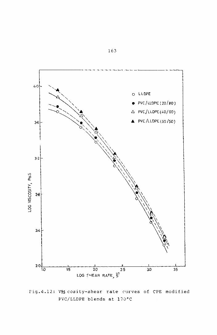
at low rates of shear. 25 ,26 Figs.4.11 and 4.12 show the
viscosity-shear rate curves of PVC/LLDPE and CPE modified
PVC /L LDPE bl ends. The strong non-Newtonian behaviour of
the blends at higher shear rates is evident from these
figures.

t/)
cP '\
>-l-t/)
0 u Vl
> ~ 0 ---.J
4,0
3.6
3·2
2.8
160
---- ePE MODIFIED
UNMODIFIED
_,. A-"'_---A-23.045 ----h.-----~ ~
---~=.-- t1 ~-~ __ -3-
57.65 () ___ - - -<)_.- _. ()_
() - - - - -- () -=-- ()- ~- -.....& ----A\-- - -!- - - - --1- ---- Lh.- '~5'2 s' ' J.\
230.L.S' ---~-- - --~-- --- -$- -- - -$=--
576,()S' A t .f. _____ ._ -- -.- - - --- -----I A
1152.0 S' -- - -~- - -- ---~- '-- - --~- - - - -'-Z1-~ 1728.0 S'
2,4 - ---1--- - - --1-- -- -- -I------I=. ----g-~- - ---8-------8---- - -:B=-
2304.0 S'
20 30 40 50 PVC, COtHEN T (010)
Fig.4.9: viscosity of the PVC/LLDPE blend as a function
ef composi t i cn at d if fe reo t sbea r rates at 170<':

E
z ~
tll
:..::.> o c:::
o f-
B G
~ ~
C P
E
MO
DI F
lED
~---
----
----
----
----
UN
MO
DIF
IED
2
, ~
o 2
4 6
~
TIM
E(
MIN
)
Fig
.4.1
0:
To
rqu
e
cu
rves
of
the
ePE
m
od
ifie
d
50
/50
P
VC
/LL
DP
E
ble
nd
s
an
d
un
mo
dif
ied
f-'
(J'I ......

V1
Cl c....
" >-t--Ul 0 U If")
:; 19 0 -I
162
4.2 i' -------------------------------.
o LLDPE
• PVC/LLDPE(20/S0)
3.£ 6. PV C /L LOPE (" 0 /60)
I A PVC/LLDPE(50/50)
J 3.0
2.6
2·2 \ \
'-:-___ --'-__________ L ____ --'--____ LI _..J
1.0 1.5 :: ,J 2.5 3.0 35
LOG SHeAR RATE, S'
Fig.4.11: Viscosity-shear rate curves of FVC/LLDPE
bler.Js at 170°C
163
4-0
o l LOPE
• PVC /LlOPE ( 20180 )
6 PVCjLLOPE(40/GO)
A PVC /LLOPE (50/50)
2.0J.--__ -.l. ____ -L ____ -L-___ ---J. ____ --'----'
1.0 1·5 20 2·5 3.0 35 LOG ~~EAR RATE S'
J
Fig.4.12: V1s cosity-shear rate curves of CPE modified
PVC/LLDPE blends at 170°C
164
Fig.4.13 shows the flow curves of typical blends
at 170°C. It is interesting to note that the flow curves
of the unmodified and modi fied blends show some
distinctive features. The unmodi f ied blend curve can be
approximated as three straight lines. These straight
lines may indicate different polymer melt structures and
the fusion of PVC particles may be the key factor in
deciding the melt structure. The initial straight line
may indicate a flow behaviour where PVC particles remain
largely unfused, while the intermediate region, a region
of shear where most of the fusion takes place, and the
final straight line may be the normal melt behaviour of
the blends. The intermediate region is not so pronounced
and may be absent for CPE modified blends supporting the
earlier proposition that CPE improves the fusion behaviour
of PVC particles. This effect can be further observed
from Fig.4.14 which is a plot of log "1 vs liT for a 20%
PVC blend at different shear rates. The slopes of these
curves are proportional to an apparent activation energy
for viscous flow. The activation energy has considerable
practical importance because it expresses the temperature
dependence of viscosity of the material. The acti' ation
energies calculated from the slopes of the lines are shown
in Table 4.1. The lower activation energies obtained from

5·7
5.6
5.5
o a.. 5.4 1./"--If'I W c:: l-t!)
Cl: <t 5·3 w :r: If)
I!> o -1
165
~~/ .. /~3~9~/.o/v LA--;:/ O~/
4 ",::"~~Ci ____ /,(J~'" lY.?---". ___ // i •
/l/w1A: / /---------/ / /
/~/ 6/ I ~ 0 A PVC I LLDPE(20/S0)
/ I I
/ / / / I.. /
/ / I cl
I r I J I /
AI ePE MODIFIED
B pveiLLDPE(40/60)
S' CPE M:>DlFIED
e pvcl LLDPE(50/50)
C' CPE MODIFIED
1/ 1;/ / 5.2 . C!(J /
III / Cl. / al / /
5.1 / /~/ 8 . 0
A I /1 A
1.5 2.0 2·5 3.0 3·5 LOG SHEAR RATE~ S1
. Fig.4.13: Shear stress--shear rate curves of modified
and unmodified PVC/LLDPE blends at 170DC

166
4.0
3.5
tIl
/, () 57G.O 5
~ 3.0 '\
> ~
in o U IJ1
> l!) o ....J
-1
A~ .~ ..
2.5 • b.~ --. ~---.~ ______ ~=__________O 2880.05' ______________ 0
--6 ______
-0
2.0._ ............ _______ ~--------~-----~ 2·,0 2-25 2 ·30
l!TxlrY Kl
Fig.4.14: Variation of viscosity with temperature of
20/80 PVC/LLDPE blend at different shear
rates

167
Table 4.1: Variation of flow activation energies of
Shear rate S-l
23.0
57.6
115.2
230.4
576.0
1152.0
1728.0
2304.0
pve/LLDPE blends with shear rate
20 per cent pve/LLDPE blend
Unmodified ePE modified kJ/mole kJ/mole
22.4 19.3
19.3 15.2
16.9 14.4
14.4 11.5
10.9 6.3
9.1 5.8
8.6 5.5
8.3 5.3
ePE modified blends show that ePE is an active flow
improver. Further, it seems that, for each blend at a
particular temperature, there is a particular shear, which
exhibits a transition from one melt structure to oth~r.
Figs.4.15 and 4.16 show the plots of log
viscosity vs liT for the pve/LLDPE and ePE modified
~VC/LLDPE blends at a particular shear rate. The
activation energies calculated fr(~ the slopes of the
straight lines are shown in Table 4.2. It can be observed

3.7
If)
d D...
~
>- 3.5 ~
Ln 0 U lfl
> ~ 0 .J
3.3 -
3,1 r-
!
no
168
I
n5 '/h1C' 1~1
0 LLDPE
• PVC /l LDPE( 20 /80 )
t::. PVC/LLDPE (40/60)
.&. PVC /L LOPE ( 50 /50 )
2,J0
Fig.4.15: variation of viscosity with temperature
of PVC/LLDPE blends with blend composi
tion at a Ehear rate of 23.0 8-1

If'1
d 0...
>-I-
4.2 -
4.1
4.0
(/)1 o 3.8 u If'1
>
8 -'
3.7
3.6
3·5 2-20
169
o LLDPE
• PVC/LLDPE(20/80)
b. PVC /LLDPE (40/60)
A PVC/ LLDPE (50/50)
2·25
,/r x 103 ~' 2-30
Fig.4.16: Variation of viscosity with temperature of
ePE modified PVC/LLDPE
composit.io:1 at a shear
!:,'1ends
rate
",ith b1E':nd -1 of 23.0 S

170
Table 4.2: variation of artivation energy of the PVC/LLDPE
blends with blend composition
Activatjon energy at a shear rate Percentage of 23.0 S-l comROsition of pvc : LLDPE Unmodified ePE modified
kJ/mole kJ/mole
0 100 23.94 19.15
20 80 19.14 17.23
40 60 17.42 15.11
50 50 13.40 10.44
tha t, the f low act i va t i on energy decreases wi t h increase
in PVC content. Also, CPE modification reduces the flow
activation energy of the blends, in all the cases.
Melt Elasticity
The melt elasticity of the blends was measured
from the extrudate swell ratio, D /D.22/24/27 e The
extrudatc. emerging frorr the capillary was collected and
the di2meter of the E:xtrudate was measurEd at. various
points. The extrudate swell ratio wns calculated as the
ratio of the diameter ef the extrud~te D to the diameter e
of the capillary die D.

171
A plot of extrudate swell ratio vs blend
composition of PVC/LLDPE b.Lend at constant shear rate IS
presentee in Fig.4.17. It can be seen from the figure
that the value of D /D e increases with the shear rate.
This is expected because the recoverable elastic energy
built up In the melt while flowing In the capillary
increases as shear rate is increased. The figure also
reveals that, for every value of shear rate, the extrudate
swell of the blends decreases with PVC content. Similar
decrease in extrudate swell ratio with increase of PVC
content, has been reported by earlier workers in other PVC
bl d 2,27
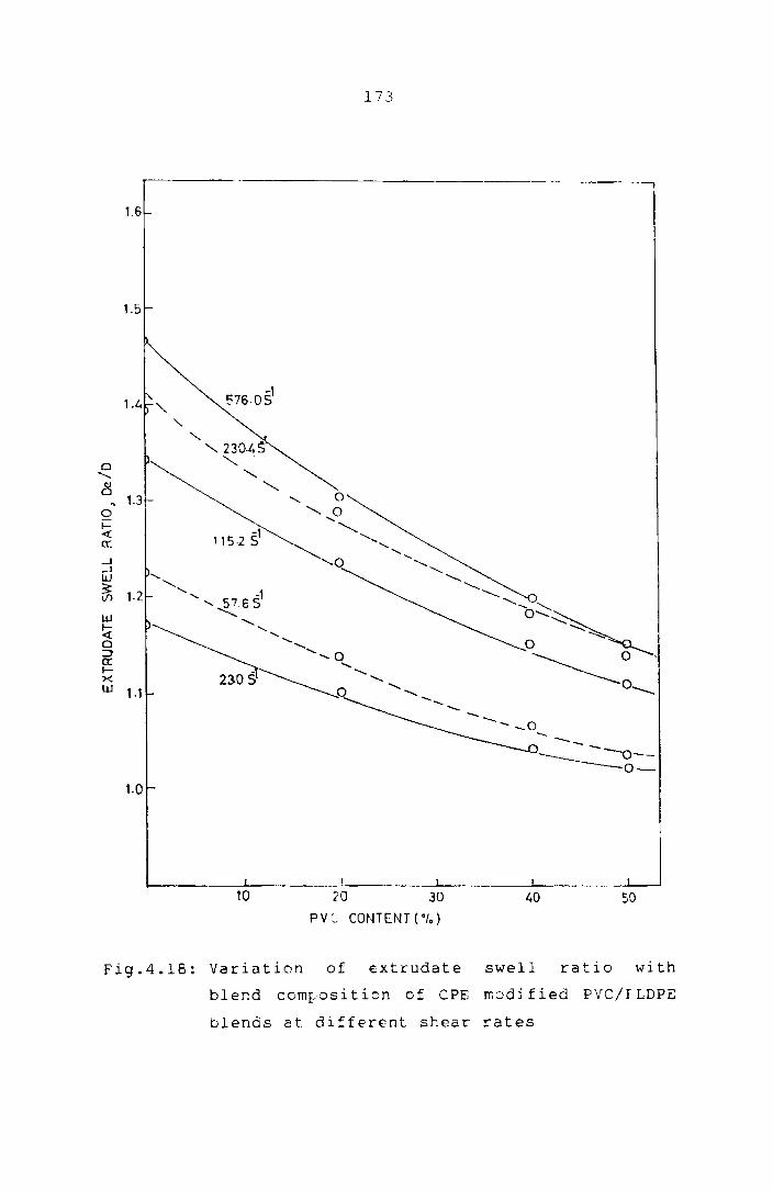
en s. The plots of extrudate swell ratio as a
function of blend composition at constant shear rate for
ePE modified blend is shown in Fig.4.18. It is found that
ePE modification does not make any significant change in
the extrudate swell behaviour of the blends.
Flow instabilities associated with shearing flow
often cause the polymer melt extrudates to have sLlrface
deformations or irregularities. A smooth extrudate can be
obtaine''l up:.o a certai" critical shear rate but beyond
this shear rate, surface roughness occurs. The roughness
increases as the shear rate increases and in some cases

o
--tJ
,·6
'·5
1'"
o 1.3 , o ~ a: -l -l W
~ W I<t o ::J er. ~-x w 1.1-
I-a
o
172
o
10 20 38 40 50
pvc CONTENT ('/.)
FiS.4.17: variation of extrudate s~ell ratio with blend
composition of PVC/LLDPE blends at different
shear rat~s
173
r---------------------------------------------------------__ ~ 1.6
1.5
Cl '-8
~ 1.3 0 1= <t ex: ---I ---I W
~ W I-et 0 :;) 0: l-X W , .,
- --_____ 0--0-
1.0
10 20 30 40 50
PVC- CONTENT(O,.)
Fig.4.18: Variation of extrudate swell ratio with
blend cornrosition of CPE rr.odj fied pvc/r LDPE
blends at different shear rates
174
the extrudate fractur(s completely and is called melt
24 fracture. The origin of the melt fracture is due to the
excessive elastic energy stored during the flow.
The surface cha~acteristics of the extrudates of
the blends are shown in Figs.4.19 to 4.26. Figs.4.19 and
4.20 show the extrudate photographs of the 20/80 and 40/60
PVC/LLDPE blends at various shear rates. The surface
roughness of these blends is first observed at a shear
rate of and 1152 s-l respectively. The
photographs of the extrud~tes of CPE modified blends are
given in Figs.4.2l and 4.22. In this case also the
surf a ce roughness sta rt s onl y at the correspondi ng shea r
rates of the unmodified blends and hence CPE modification
does not seem to affect processing as far as the surface
chc~acteristics are considered.
Figs.4.23 and 4.24 show the extrudate
photographs of the unmodified and CPE modified LLDPE. The
surface roughness develops at a fairly low shear rate of
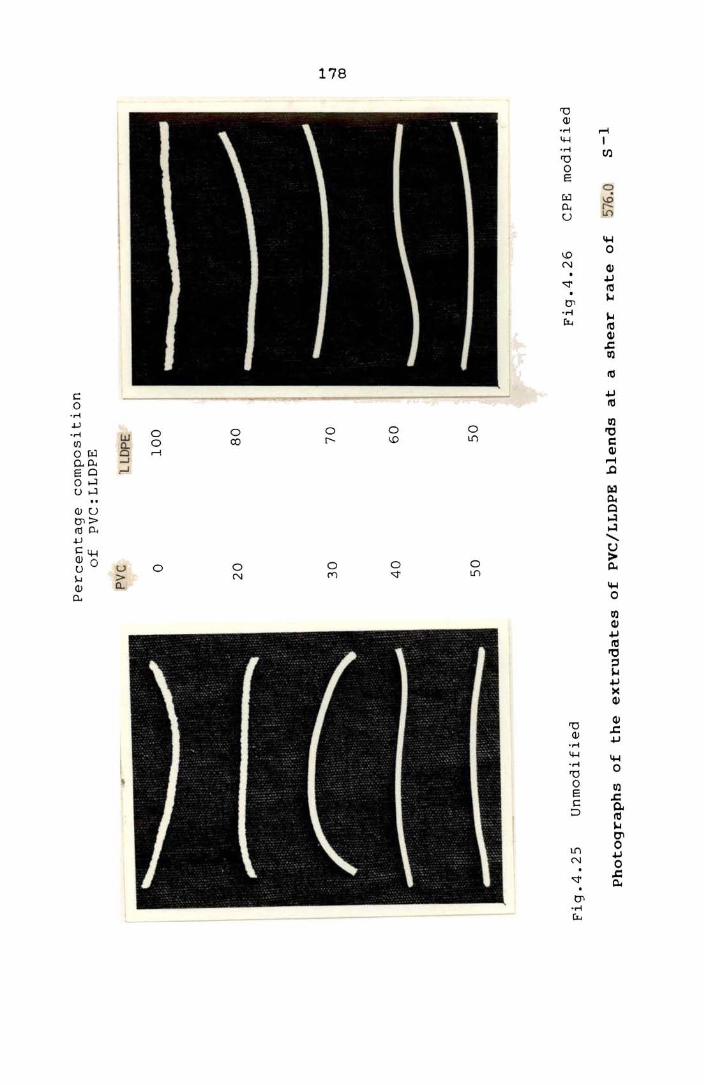
-1 115.2 S • Figs.4.25 and 4.26 show the effect of adding
PVC to LLDPE on the surface c~aracteristics of the latter
-1 at a shear rate of 576.0 S • Surtace roughness disappears
with the progressive addi_ion of PVC. This shows that

Fig
.4.1
9
20
/80
P
VC
/LL
OP
E
(un
mo
dif
ied
)
-1
Sh
ea
r
ra
te
(S
)
23.0
57
.6
11
5.2
23
0.4
57
6.0
23.0
57
.6
11
5.2
23
0.4
57
6.0
11
52
.0
Fig
.4.2
0
40
/60
P
VC
/LL
OP
E
(un
mo
dif
ied
)
Ph
oto
gra
ph
s o
f th
e
ex
tru
da
tes
of
PY
C/L
LD
PE
b
len
ds
at
va
rio
us
sh
ear
ra
tes
~ .., ~

Fig
.4.
21
20
/80
P
VC
/LL
DP
E
(CP
E
mo
di
fied
) F
ig.4
.22
4
0/6
0
PV
C/L
LD
PE
(C
PE
mo
dif
ied
)
Ph
oto
gra
ph
s o
f t
he
ex
tru
da
tes
of
PVC
/LL
DPE
b
len
ds
at
va
rio
us
shea
r
rate
s

-1
Sh
ea
r
ra
te
(S
)
23.0
23.0
57
.6
57
.6
• --~
• •
• -~
• •
Fig
.4.2
3
LLD
PE
(un
mo
dif
ied
) F
ig.4
.2
4
LL
DPE
(C
PE
m
od
ifie
d)
Ph
oto
gr
ap
hs
of
the
extr
ud
ate
s o
f L
LD
PE
at
va
rio
us
sh
ea
r
ra
tes
Fig
.4.2
5 U
nm
od
ifie
d
Percen
tag
e
co
mp
osi
tio
n
of
PV
C:
LL
DP
E
PV
C
lLll
PE
o 1
00
20
8
0
30
7
0
40
6
0
50
5
0
Fig
.4.2
6
CPE
m
od
ifie
d
Ph
oto
gra
ph
s o
f th
e
ex
tru
da
tes
of
PV
C/L
LD
PE
b
len
ds
at
a sh
ea
r
ra
te o
f 57
6.0
S
-1
... ..., (Xl

179
elastic nature of the melts of the PYC/LLDPE is reduced by
the addition of pvc. This behaviour is in conformity with
the die swell characteristics of PYC/LLDPE blends.
MODIFICATION OF PVC/LLDPE BLENDS BY CO-CROSSLINKThlG US:rn:; DCP
Crosslinking of polymers improves their
mechanical stability at high temperature, creep and
tensile properties. Polyolefines are sometimes modified
with organic peroxides to alter their processability and
mechanical . 29,30
propertles. It is known that the
effectiveness cf the chemical crosslinking of polyolefines
can be increased by the use of co-agents. Various radical
initiators, amines etc., can act as co-reactants/co-agents
h · h h h h . 1 . b h' 29 w lC en ance t e c emlca reactlon etween t e reSlns.
The use of such co-agents is of great importance in the
case of polymers containing tertiary carbon atoms in the
chain. The abili ty of organic peroxides to function as
crosslinking agent for PYC also has been described
. 30-33 earller. If two pOlymers which are incompatible can
be co-crosslinked I it may be possible to achieve better
properties and better technical performance. The
1 it era t ure conta ins i nforma t lon a bout the improvement in
physico-mechanical properties of immiscible polymer blerds

180
h h 1 ° kO 34,35 t roug co-cross ln lng. Nakamura et al.36
studied
the effect of partial co-crosslinkirg on the mechanical
properties of PVC/PE blend. In this study the effect ef
modifying PVC/LLDPE blends by dicumyl peroxide is
reported, since such modification is likely to introduce
some co-crosslinking in PVC/LLDfS blends, it may improve
the compatibility, mechanical behaviour, thermal
resistance, creep resistancE, ~olvent resistance etc., of
the blends.
Experimental
Polymer bleods were prepared on a Brabender
plasticorder. Mixing conditions were 160°C and 30 rpm.
LLDPE was added first, then PVC with its heat
stabiliser(s) and finally DCP was added. Three different
stabilisers viz., Tribasic lead sulphate (4 parts per 100
parts of PVC ie., 4phr), IrgastabA70 (4phr), ZnO
(4 phr)/MgO (4 phr)/stearic acid (3 phr) were used in this
study. Test samples were prepared by compression m~ulding
at l80°C for 3 minute~. The tensile propc:rti€E ef the
blends were determined on a Zwick univers2l testing
mschine using a cross head speed of 50 mm/min.

181
Results and Discussion
For determining the effect of co-crosslinking, the
higher molecular weight polymers (PVC-2 and LLDPE-I) were
used. Fig.4.27 shows the Brabender torque curves of the
30/70 PVC/LLDPE blend. A large increase in torque value
is obtained upon DCP addition. It shows that DCP
introduces some crosslinking in the matrix. When the
samples for tensile testing were prepared, mixing was done
at 160°C to prevent crosslinking during mixing permitting
it to occur during compression moulding done at 180°C.
Another observa t i on from the figure is t ha t there is a
pronounced increase in the band width of the torque curve
at the end of mixing in the case of DCP modified blends.
This may be due to the higher crosslink density at the end
of mixing.
It is well known that crosslinking changes the
stress-strain behaviour of the polymers. Fig.4.28 shows
the tensile stress-strain curves of an unmodified and DCP
modified 20/80 PVC/LLDPE blend containing different PVC
stabilisers. All the blends show some improvement in the
yield strength with modification by DCP which shows that
the matrix has become stronger by the crosslinking an:3 from
the better compatibility re2ulting from it.

E
z '"
w
=>
o 0:: o I-
6
WIT
fIOU
T
OC
P
WIT
H
OC
P
\ \ \
2
2 4
6 8
2 4
G
8
TIM
E (
MIN
)
Fig
.4.2
7:
Bra
ben
der
torq
ue
cu
rves
of
the
un
mo
dif
ied
an
d
DC
P
mo
dif
ied
P
VC
/LL
DP
E
ble
nd
(3
0/7
0)
at
18
0°C
f-'
00
N

0 .~ .
cJ')
cJ')
I.J..I
0:
I-
cJ')
16
12 B~
/ //
UN
MO
DIF
IED
4~
1 T
BlS
2 IR
GA
ST
AB
3 Z
nO I
MgO
/ SA
100
200
300
2
3
I~
100
ST
RA
IN( ·
f.)
~
zoo
,r--3
7.
MO
DIF
IED
300
Fig
.4.2
8:
Str
ess-str
ain
cu
rves
of
an
u
nm
od
ifi,
..,d
an
d
DC
P m
od
ifie
d
PV
C/L
LD
PE
(2
0/8
0)
ble
nd
co
nta
inin
g
dif
feren
t sta
bil
isers
I-'
CP
w

184
Since organic peroxides are also likely to
introduce degradative reactions In the polymer, the
mechanical behaviour of the samples containing three
different PVC stabilisers is compared in Fig.4.28.
Eventhough TBLS is staining and shows maximum colour
development, it shows maximum strength. Irgastab A 70
(amino crotonate) being metal free shows least colour
development, but lower mechanical ~trength compared to
TBLS. 37 This is probably due to the plasticising action
of this liquid stabiliser. MgO/ZnO/stearic acid
stabilised mixture also develops colour. It shows the
lowest yield strength and maximum elongation at break.
This is likely to be due to a lower crosslink density in
the matrix resulting
stabiliser.
from a higher loading of the
The effect of various levels of DCP on the
tensile strength of PVC/LLDPE blends is shown In
Fig.4.29. The blend having 0.5 phr DCP does not show any
significant' improvement in tensile properties. The blend
which has 1.5 phr DCP exhibits m'uch better mechanical
properties, but colour development is very pronounced.
So an optimum concentration of DCP may be taken as 1 part
per 100 parts of PVC and LLDPE.

, I rI-!J Z
25-
w 10rc:: r-lfl
W -l Vi Z W r-
5
o 10
185
o DCP 15phr
DCP 10po,r
• DCP 05phr
UNMODIFIED
I
20 30 50 PVC CONTENT(°r.)
Fig.4.29: Tensile strength of PVC/LLDPE blend as a
function of composition--Effect of DCP
concentration

186
RADIATION MODIFICATION
When polymers are irradiated, chemical compounds
are created which ln turn lead to permanent changes in
certain properties. The absorption of radi~nt energy can
cause the breakdown of the chemical bonds. Breakage of
the bond gives rise to free radicals which crosslink with
other radicals. Consequences of the irradiation of
polymers are not only the formation of crosslinks but also
molecular breakdown due to breakage of the main chain. As
a result, irradiation can lead to improvement
(crosslinking) or degradation (breakdown) of the
. . 38,39 propertles of the materlal. The chemi cal s t ruct ure
of the polymer and the radiation conditions decide the
dominating reaction. The properties of both PVC and PE
can be modified by high energy radiation. 40 ,41 Since such
modifications are likely to introduce some co-crosslinking
in the PVC/PE blend, it may improve the compatibility and
other properties of the blend. Further, while chemical
crosslinking is known to affect crystallinity of the
matrix and hence may adversely affect the mechanical
behaviour, radiation crosslinking is found to affect
42 crystallinity only less severely.

187
Experimenlal
Polymer blends were prepared on the Brabender
plasticorder. M i x in g con d i t ion s we r e 160 ° Can d 30 rpm.
LLDPE was added first, then PVC with its heat stabiliser
and finally 1 phr DCP was added as accelerator. Test
samples were moulded at 160°C fer 3 minutes to minimise
DCP induced crosslinking.
subjected to gamma radiation
Then
of
such samples were
different dosages.
Tens i 1 e propert i es were det ermi ned on a Zwi ck un i ver sa 1
testing machine using a cross head speed of 50 mm/min.
Results and Discussion
done by
dosages.
Radiation modification of PVC/LLDPE blends wG\S
subjecting the blends to various radiation
Table 4.3 shows the variation of tensile
propert ies and colour development of the unmodified and
radiation modified blends of 30/70 PVC/LLDPE blends with
radiation dosage. As in the case of DCP modification,
higher dosages give rise to degradations leading to colour
development. An irradiation dcoage of about 3 Mrads is
found to be an optimum giving rise to some crosslinking in
the matrix without serious degradation. Fig.4.30 gives a
188
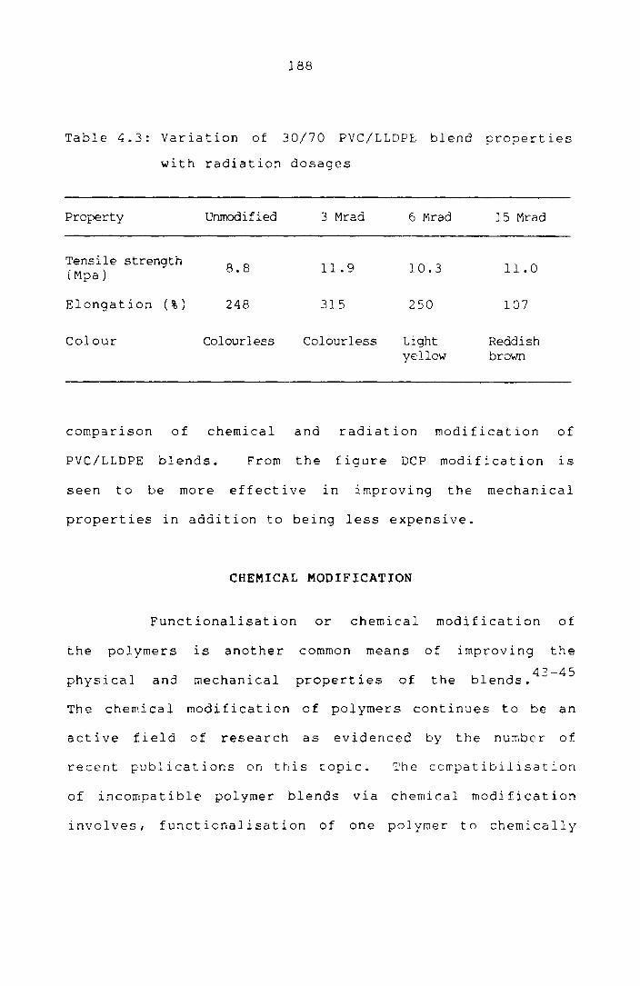
Table 4.3: Variation of 30/70 PVC/LLDPE blend properties
with radiation dosages
Property Unmodified 3 Mrad 6 Mrad 15 Mrad
Tensile strength 8.8 11.9 10.3 11.0 (Mpa)
Elongation ( % ) 248 315 250 107
Colour Colourless Colourless Light Reddish ydlow brown
comparison of chemical and radiation modification of
PVC/LLDPE blends. From the figure DCP modification is
seen to be more effective in improving the mechanical
properties in addition to being less expensive.
CHEMICAL MODIFICATION
Functionalisation or chemical modification of
the polymers is another common means of improving the
physical and mechanical properties of the blends.43
-45
The chemical modification of polymers continues to be an
active field of research as evidenced by the number of
recent publications on this topic. The compatibilisation
of incompatible polymer blends via chemical modification
involves, functionalisation of one polymer to chemically

c Cl. ::E ::r:' to Z W a: tIf)
25
15
w 10 -' Vi z W t-
5
, \
10
189
• UNMODIFlED
6 RAD1AT]ON MODIFIED
o CHEtv1JCALLY MODJFIED
20 30 50 PVC CONTENT (0/.)
Fig.4.30: Tensile strength of PVC/LLDPE blend as a
function of composition--Comparison of chemical~radiation modification
190
link with the molecules of another type of polymer. For
example, pp can be functionalised to chemically link with
NBR during melt .. 43 mlxlng. Good mechanical properties are
generally obtained from the linkages formed between the
molecules of the two polymers. The compatibility
enhancement ln polyolefine/styrene maleic anhydride via
polar interactions was recently reported by Simmons et
al. 46 In this study acrylic acid, maleic anhydride,
phenol i c res i nand P-pheny 1 ene d i ami ne a re used for the
chemical modification of PVC/LLDPE blends. Dicumyl
peroxide is used as a sensibilizing agent in the case of
acrylic acid and maleic anhydride. 4l
Experimental
PVC/LLDPE blends of various compositions (PVC
content varied from 0 to 50% of the total polymer weight)
were prepared on the Brabender plasticorder. The level of
modifiers and stabilisers used for a 20/80 PVC/LLDPE blend
is shown in Table 4.4 as an example.
FunctionalisaLion
a) Acrylic acid/maleic anhydride
PVC with its heat stabiliser (2.5 phr tribasic
lead sulphate) was melt mixed with LLDPE at a temperature

191
Table 4.4: Recipe for the 20/80 PVC/LLDPE blend
PVC and Stabiliser
PVC = 8 9 (20% of total polymer)
TBLS 0.2 9 (2.5 parts per 100 parts of PVC)
Po1yethylene
LLDPE = 32 9
Modifiers
a) Acrylic acid
DCP
b) Maleic anhydride
DCP
= 1·2 9 (3 parts per 100 parts of PVC and LLDPE (3phr))
0.08 9 (0.2 phr)
= 1·2 9 ( 3 phr)
= 0.08 9 (0.2 phr)
c) P-pheny1enediamine= 1·2 9 ( 3 phr)
d) Phenolic resin-l = 1.2 9 ( 3 phr)
snC1 2 0.16 9 (0.4 phr)
MgO = 0.003 9 (0.07 phr)
e) Phenolic resin-2 1·2 9 ( 3 phr)
snC12 = 0.16 9 (0.4 phr)
MgO = 0.003 9 (0.07 phr)

192
of 150°C and 30 rpm. After 2 minutes, Dep (0.2 phr) was
added as the free radic~~ precursor/ and then acrylic acid
or maleic anhydride (3 phr) was added. Mixing was
continued for another 3 minutes.
b) Phenolic resin modification
Mixing was done at a temperature of 180°C and
30 rpm. After melt mixing of PVC and LLDPE/ phenolic
resin was added along with Sne12
as the accelerator.
After 3 min. MgO was added to neutralise the free acid.
The total mixing time was 8 min.
c) P-phenylene diamine modification
The mixing conditions were 18Doe and 3D rpm.
P-phenylene diamine (3 phr) was added after the melt
mixing of PVC and LLDPE. The mixing was continued until
the torque reached a steady value.
The test samples were prepared by compression
moulding at 180°C for 3 min. in a laboratory hydraulic
press. Tensile properties were determined on a Zwick
universal testing machine using a cr-oss head speed of
50 mm/min.

193
Results and Discussion
Fig.4.31 shows the Brabender torque curves of
the unmodified and acrylic acid modified PVC/LLDPE (40/60)
blends at 180°C. A large increase in torque occurs with
the addition of acrylic acid along with DCP (0.2 phr).
The Increase in torque (viscosity) is probably due to
1) co-crosslinking of the polymers in presence of
carboxylic acid and/or 2) grafting of carboxylic acid on
to the polymer chains. Since DCP concentration was low,
the grafting of carboxylic acid is probably the dominating
. 47,49 reactIon. .
The mixing temperature seems to be very critical
for successful chemical modifications. When the mixer
temperature is ~ 180°C the torque curves of the acrylic
acid modified blends resemble those of the unmodi fied
blends without any significant increase in torque values
(Fig.4.32). Hence for preparing test pieces of the
modified blends, mixing was done at 150°C and then
compression moulding at 180°C for sufficient time for the
modifying action to take place.
The preferred site for the grafting IS possibly
the tertiary carbon atom of LLDPE and the carbon atom to

32 2!J
E
16
'z , L;
J a et
o t-
8
'UN
MO
DiF
1ED
I O~
4 8
o T
lME
( M
IN)
o 4 TIMEu,.,n~)
8 12
Fig
.4 .
31
: B
rab
en
der
torq
ue-c
urv
es
of
the
40
/60
P
VC
/L L
DPE
b
l en
d
at
18
00
C
I--' ~ ~

3J
, .... ~ :-
-
~ 1G
r
:~ I
§ I
o f-
I I Br o
\ !
0
15
0C
4 TJME(~~lN )
8
o I '"' Ti~.1~(M1N )
Fig
.4.3
2:
Bra
ben
der
torq
ue-c
urv
es
of
the
acry
lic
acid
m
od
ifie
d
30
/70
PV
C/L
LD
PE
b
len
d at
15
0°C
an
d
18
0°C
i-'
1.0
Vl

196
which the chlorine atom is attarhed In PVC. Grafting can
give rIse to strong interaction between the phases.
Another observation is that, with increase of PVC content,
there is a pronounced i ncrea se in the bandw i dt h 0 f the
torque curve at the end of mixing (Fig.4.33,. Similar
beha v i our wa s also observed whe n L LDPE a lone wa s cross-
linked with various concentrations of DCP. Hence it may
be concluded that the Increase in the bandwidth of the
curve is due to higher crosslink density and that PVC is
more susceptible to crosslinking and modification than
LLDPE.
The acrylic acid grafting on the polymer chains
was confirmed by IR spectra. IR spectra of the modi fied
blends (excess carboxyl ic acid free) were taken wi th a
Beckman Infrared spectrophotometer. Fig.4.34 shows the IR
spectra of unmodified, acrylic acid modified and acrylic
acid--DCP modified LLDPE. It shows that acrylic acid
grafting occurs only in the presence of DCP. The band at
1730 cm -1 shows the presence of )c=O groups. The IR
spectrum of 30/70 PVC/LLDPE blend also shows acrylic acid
grafting (Fig.4.35).
The variation of tensile strength with composi
tion for thE unmodified and carboxylic acid modified

32
E 2
4
z ~ g 1
6 ~
8
I I I
pvc/
LLD
PE
(O /
10
0)
I .
, i : . I ,
. P
VC
/
LLD
PE
:( 3
0/7
0)
.P'J
C /
LL
DP
E( S
O/5
0)
01
I!
! I
I I!
I
~ g
12
4 8
12
L. 8
12
-:',
1E
(tvI
!\;
TIIv
1E:M
1N)
T1M
EU
v'!lN
)
Fig
.4.3
3:
Vari
ati
on
in
th
e
natu
re
of
the
Bra
ben
der
torq
ue
wit
h
PVC
co
nte
nt
f-'
\,0
...
J

GOI-\
.. --
LLO
PE

\- ----------
l ----'-~ 0
r---, 0
i ,-<)
'-------------iO _ 0
:r:: t' --- Cl- 'V
I -- I \V
.-~=--=--===.. ... -..,
/----- I l.-< I -....
!
I /
'7J I 0
\ ~f: E
i ~-
!
I
I 0-
"'--
\.~
\ g
"'-. .,'
I ...... '~----- u-- I
,
! ---- I I '<.'
~ ,.---------==-:=::-:> Is -,..., u
I /' ro
I ~ -, ",
! i r-
i 0 ------=-===-~-=.:> (1
t'
I r--
, ,'- .r---:
I '-- r-- i>-o
I~ .-i r-i
0 I"l
!~. >.
I \..J
U-l 0 :.j U
! 0_ i<: :1.1
0 -, (;~ ro
I .-l ~
I .-l
-:=?
.......... L!J ~
U ,- 0 'V
> I ~
CL I >- c
CJ i E r-i
\ ;0 ::l ..0 le, \..J In ..,.;
r'J W
I u 0-Q.I Cl 0.. ...:l
'-- :r: rJj ...:J
-----~ -u----- I I '--
----- 0 ..---------_._-----------:-..:..=:.::. 10 0:: >
// ju H c.. I~'; I
! ! l:", er!
l f le -<:;
I 0-'
-t; --'''-'--- ----- .. -------, I i-: -., C·} r.:..
(:)
(Civ ) :; )r~\tj J ):.'6 ~ J"1tL

200
PVC/LLDPE blends is sho\<:n in Fi9.4.36. Go:)d ir.:provement
in tensile strength is found to result fro~ the chemical
modifiration. ! i 9 .4 . 37 s how ~ the \- a r i c t i 0:1 i nth e y i e 1 d
stress. I t l sal so f 0 u ne" ;\ a tin C J: e <:; sin 9 t ~ e con c e n t !" a -
tions of acryJ ie acid/r.:aleic anhydrioE: or DCP does not
result 1n further in:prv\lE-rnent in properLies. Chemical
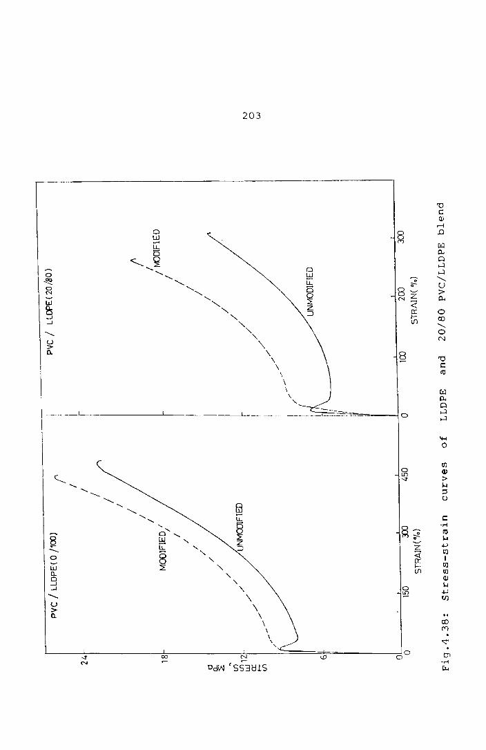
~odification lS found to vary the stress-s~!"ain beheviour
substantially (Fig.4.38).
Fig. 4 . 39 9 1. V est he e f f e c t 0 f ch en.i c .~d me Cl i f i ca
tions using phenolic resin and P-phen~lene diamine on the
tensile strength of PVC/LLDPE blends. The abili ty of
phenolic resin to improve the ultimate properties of PE or
pp ble:1d with NBR has previously bee") reported. Both
types of phenolic l-esins (high methylol type and resin
ccntain:ng hexamine) were used for the technological
compatibilisation. Even though these modi Eications result
in marginal improvements, it is not comparable with the
improvement obtained with carboxylation.
CARBOXYLIC ACID MODIFIED PVC/LLDPE BLEt~D AS fIN ADHESIVE
Earlier studies show that the intr.oduction of
some polar groups can increase the adt€~ive bond strEngth
of pclyolefines to various materials (~pecially metals.

201 --------------------- .. -------... -.------~
28
UI\\'vXiU!I-Il::Q
o MALEIC ANINDRIDE tv(D1FIED
24 • ACRYLIC ACID rv'ODIFIED
\
20
1G
& 2:
'\ ~ f-<....') L. UJ
12 Cl: 1-(f)
W -.J
V) z: W f-
B
o 10 20 30 40 50
PVC CONTENT("Io)
Fig.4.36: variation of tensile strength with
composition for the unmodified and
carboxylic acid modified PVC/LLDPE blends

1 3
12
1 1 .
202
.. --.---. -- --_ .. _-_._----- .. _. ------.---------
MmF1ED rln) / (ACRYLIC A/
•
/ /e
------__ L-__ .- -. ---:::!-:' :----__ ---J.'::--____ ..."., __ . __ ---''--_
o 10 20 30 40 ~)O PVC CONTENT( 0'0)
Fig.4.37: Variation of yield stress ~ith composition
of PVC/LLDPE blends
24
18
a ~ If)
If) 12
w
0:
: !-
If)
,,- J~
11
'"
pvc
/ LL
DP
E( 01
100
)
/ /
./
MO
D1F
IED
/
/
/
/
/ /
/
/ / /
/
/ /
/ /U
NM
OO
FIE
D /
/ / I
r I I r i I I i f I ! 1
r ~I ! i/I :1/
/
.--'"
/'
./
./
PV
C /
LL
DP
E(
20
/80
)
t / / tv
()D1F
IED
/ / / /
/ /
/ /
/ /
/ /
/
UN
MO
DIF
IED
01
, ,
, r
, 1
' o
150
JX)
450
0 10
0 20
0 30
0 S
TR
AIN
(%)
ST
RA
IN(
"10)
Fig
.4.3
8:
Str
ess-s
train
cu
rves
of
LL
DPE
an
d
20
/80
P
VC
/LL
DP
E
ble
nd
I\J o w

d [!.
:L,14
~ 10~1 .-J
G 2 W !-
6
2
o 10
A.
o
•
20
204
P. PHFNYLE: £ DIA'<l!<::: MCfJiF1E D PHENOLIC RESH~ 2 M'X)IFlED
PHEr\j:U~ RESiN 1 MJJIFiEO
30
Fig.4.39: Variation of tensile
composition of PVC/LLDPE tlend~
wit.h
205
Ethylene copolymers with polar groups were found to have
such adhesive properties. The polarity of the groups on
the polymer chcin lS utilised to support adhesion to
. . 1 12 var10US mater1a s. 48 Hjertberg Et al. have studied the
effect of various functional groups on the adhesion
capability of polyolefine to metals. They found that
carboxylic acid is very effective in increasing the
adhesion between the po1yethylene and metal. In this
study acrylic acid and maleic anhydride modified PVC/LLDPE
blend, is investigated fur its adhesive properties with
metals.
Experimental
Thin metal sheets (steel and aluminium) were
cleaned wi t h emery paper and then degreased. Then the
sheet metal and the polymer were pressed together in a
laboratory hydraulic press at 180°C for 3 min at
120 kg/cm 2 Then the metal/polymer sample pressure. was
taken out of the hydraulic press, cooled to room
temperature and the peel resistance (adhesive bond
strength) of the joint was determined. The adhesive bond
s t reng ths between meta 1 a nd modi f i ed pol ymer bl ends were
assessed from the resistance to peeling of a 25 mm strip
polymer sample from the metal surface, angle of pE.eling
being 180 0 at 50 mm/min test speed.

206
Results and Discussion
PVC/LLDPE blends are found to show good adhesive
properties to metals such as steel and aluminium. The
bond strength is found to be much superior in the presence
of pvc. This result confirms our earlier observation that
chemical modification of the PVC/LLDPE blend is more
efficient than that of LLDPE alone. The peel strength of
the carboxylic acid modified LLDPE and its blend with pvc
is given in Table 4.5.
Table 4.5: variation of peel strength of the carboxylic
acid modified PVC/LLDPE blends with blend
composition
Percentage composition of PVC : LLDPE·
o 100
20 80
30 70
40 60
50 50
PEEL RESISTANCE (N/mm)
Acrylic acid treated Maleic anhydride treated
Steel Aluminhnn Steel Aluminium
8.90 6.62 5.24 3.48
9.82 8.25 5.86 4.47
15.34 10.81 6.26 4.71
12.00 10.12 5.50 4.41
11.68 7.37 3.51 2.82

207
The peel strength of the modified PVC/LLDPE
blends is found to improve steadily with PVC content but,
when the PVC content exceeds 30% of the total weight, the
strength of the polymer matrix IS not suffl~ient to
support the high bond strength. It is found that the
i nt roduct ion of pol ar funct 2 i.a 1 groups to PVC/LLDPE blend
increases adhesion and blend compatibility which ~kes them
suitable for sophisticated end uses In place of me e
expensive polymers.
The water and temperature resistance of the
adhesive bond is important when its practical utility is
considered. To assess the water resistance of the
adhesive bond the specimens were immersed in boiling
water. The resistance to boiling water IS shown in
Table 4.6.
The boiling water resistance of the adhesive
bond for acrylic acid
high but the modified
resistance even after
not very modified LLDPE alone IS
PVC!LLDPE blends show very good
in boiling 50 hrs of immersion
water. This observation is also In conformity v.Jith the
earlier observation that the presence of pvc increases the

------------- ---------31cr:G Cf.:~1pC..=iLj:::;;;
r't: r- C E:;~ tag e
?vr : U nr-s
c leO
')" ~ , 80
~!:J le)
40 60
50 50
I Lit i (-; 1 ;;- Ej e 1 E~:: €!~g t h
6.62
8.25
lCi.80
10.10
7.37
?f:€ol [:rength (N/n~r.") cf:€', :. :-, :. '( E. ~ I. irnrne r ~: l \.. ~-;
5.62
:-' • -:<,1
4.62
4.28
a ,3 h e s i \' e b 0 n d s t r en g t h • Ti~e chemical resi~tance of the
acrylic acid mrdified bl~nd~ was determined by keeping it
in the respecti'.'€ chemicals at a;:-,oiE:-nt tenlpt'Lature for O!1€
The perCt'nt agE' i nor-case j n 'weight ef the acrylic
EciC m0~ific6 blEn6~ in oil, tcl1J( ne -. r ,., --. - ,.-, t r - t c" U"· --) C _'; . '- t - 1._ a e l .-:: - \ ~ 3

209
Table 4.7: Chemical resistance of the acrylic acid
modified PVC/LLDPE blends
Percentage PERCENTAGE INCREASE IN WEIGHT
compos i- At room temp. for tion of
7 days At 70°C for 24 hrs
pvc : LLDPE Oil Toluene Con.HN03 Oil H2O
0 .. 100 5.0 21.4 3.3 30.6 1.4
20 80 2.7 28.6 2.6 30.0 1.6
30 70 2.4 25.6 2.4 17.1 2.1
40 60 1.0 23.8 3.2 14.3 1.6
50 50 1.3 25.0 3.8 13.1 2.1
The blends are found to have good chemical
resistance in these media. The blends also possess good
dimensional stability in hot oil and hot water.
210
REFERENCES
1. C.Sadrmohaghegh, G.Scott and Setudeh, Polym. Plast.
Technol. Eng. 24 (2 & 3) 149 (1985)
2. Raija Mikkonen and Antti. Savolainen, J. Appl. Polym.
Sci. 39 1709 (1990).
3. T.Palotas, J.Somfalvi and K.KupL Int. Polym. Sci.
Technol. 17 (2) T/19 (1990).
4. A.Ghaffar and G.Scott, Eur. Polym. J. 14 631 (1978).
5. A.Ghaffar, C.Sadrmohaghegh and G.Scott, Eur. Polym. J.
17 941 (1981).
6. L.K.Sanghi, A.S.Bhattacharyya, B.Mukherjee, A.K.Sen,
P.P.De, Anil K.Bhowmik, Proc. Int. Wire Cable Symp. 38
306 (1989).
7. Ralph H.Thomas and S.Thomas, Polymer News, 8 (6) 169
(1982).
8. D.R.Paul and S.Newman (Eds), Polymer Blends, Academic
Press, 1, Chapter 6 (1978).

211
9. J.A.Manson and L.H.Sperling, Polymer Blends and
Composites, Plenum Press (1976).
10. O.Olabisi, L.M.Robeson and M.T.Shaw, Polymer-Polymer
Miscibility, Academic Press, Chapter 5 (1979).
11. L. A . Ut r a c k i, Po 1 ym • P 1 a st. Te c h n 0 1. En g . 22 ( 1) 2 7
(1984).
12. Daniele Romanini, Polym. Plast. Technol. Eng. 19 (2)
201 (1982).
13. M.M.Coleman, C.J.Serman, D.E.Bhagwager and
D.C.Panita, Polymer 31 (7) 1187 (1990).
14. M.Xanthos, Po1ym. Eng. Sci. 28 (21) 1392 (1988).
15. P.Bataille, C.Jelicouer and H.P.Schreiber, Society of
Plastic Engineers Antec. 30th Annual Technical
Conference, New York, Technical papers, p.475,
(1980).
16. C.E.Locke and D.R.Paul, J. Appl. Polym. ScL 17 2597
(1973).

212
17. H.Munstedt, J. Macromol. Sci.-Phys. B14 (2) 195
(1977).
18. J.Francis, K.E.George and D.J.Francis, Kautschuk
Gummi Kunststoffe 43 (3) 193 (1990).
19. C.H.Hoffmann, Polym. P1ast. Technol. Eng. 20 (2) 197
(1983) •
20. J.T.Lutz, Polym. Plast. Technol. Eng. 21 (2) 99
(1983).
21. C.L.Sieglaff, Polym. Eng. Sci. 9 81 (1969).
22. U.K.Saroop, K.K.Sharma and K.K.Jain, J. Appl. Polym.
Sci. 38 1421 (1989).
23. B.Rabinowitsch, Z. Physik. Chem. A145 1 (1929).
24. J.A.Brydson, Flow Properties of Polymer Melts, Second
edition, George Godwin, London, Chapter 3 (1981).
25. C.D.Han, Multiphase Flow in Polymer Processing,
Academic Press, New York (1981).

213
26. L.A.Utracki and M.R.Kamal, Po1yrn. Eng. Sci. 22 96
(1982).
27. K.T.Varughese, P.P.De and S.K.Sanyal, J • Vinyl
Technol, 10 (4) 166 (1988).
28. E.B.Bag1ey, J. AppJ. Phys. 28 557 (1957).
29. D.W.Woods, W.K.Busfield and I.M.Ward, Plast. Rubb.
Process. App1. 9 (3) 155 (1988).
30. J.de Boer an1 A.J.Pennings, Polymer 23 (13) 1944
(1982).
31. L.Ka1afski and V.M.Zhiznevskii, Int. Po1ym. Sci.
Techno1. 14 (5) T/73 (1987).
32. L.L.Valdiserri and G.V.Reed, Rubber World 170 (5) 40
(1974).
33. Vratislav Duchacek and Antonin Kuta, J. Appl. Polym.
Sci. 27 1549 (1982).
34. Y.Nakamura, K.Mori and R.Takesawa, Int. Polyrn. Sci.
Techno1. 7 (7) T/9 (1980).

214
35. Y.Nakamura, K.Mori and R.Takesawa and M.Saito, Int.
Polym. Sci. Techno1. 7 (2) T/89 (1980).
36. Nakamura, Yoshoro, Watanabe, Akira, Mori, Kuinoi,
Tamura Kosaku, Miyazaki Hitosi, J. Polym. Sci. 25 (3)
127 (1987).
37. w.v.Titow, PVC Technology, Elsevier Applied Science
Publishers, fourth edition, Chapter 10, p.347 (1984).
38. G.S.Ivchenko, T.K.Shaposhnikova, S.N.Ll'n,
B.M.Vanyushkin and V.G.Konkov 8 (7) T/78 (1981).
39. Z.S.Egorova, V.I.Dakin, V.L.Karpov and R.S.Barshtein,
Int. Po1ym. Sci. Techno1. 7 (9) T/3 (1980).
40. W.Birkigt, R.Mul1er and K.Posse1t, Int. Polym. ScL
Techno1. 15 (5) T/12 (1988).
41. M. Ma teev and M. Ni kol ova, P last. Rubb. Process. Appl.
15 241 (1990).
42. L.M.Kulkarni and R.Mashelkar, Polymer 22 1665 (1981).

215
43. A.Y.Coran and R.Pate1, Rubb. ChCil. Technol. 56 (5)
1045 (1983).
44. N.e.Liu, W.T.Baker and K.E.Russel1, J. Appl. Po1ym.
Sci. 41 9 (1990).
45. D.N.Schulz and S.R.Turner, Rubb. Chem. Techno1. 55
(3) 809 (1982).
46. A.Simmons, W.E.Baker, Po1ym. Cornrnur.. 31 (1) 2 (1990).
47. L.P.Kru1 , Yu I.Matusevich and A.M.Nikiforov P1ast
MassYI 7 77 (1990).
48. T.Hjertberg and J .E.Lakso, J. Appl. Po1ym. Sci. 37
1287 (1989).
49. Jayarnma Francis and K.E.George, J. E1ast. and Plast.
(in press).