Embed Size (px)
Citation preview
CHAPTER 4 Stress Transformation

ANALYSIS OF STRESS
• For this topic, the stresses to be considered are not on the perpendicular and parallel planes only but also on other inclined planes.
x
z
y
b
A
a
b a
P P
(A body subjected to load P)
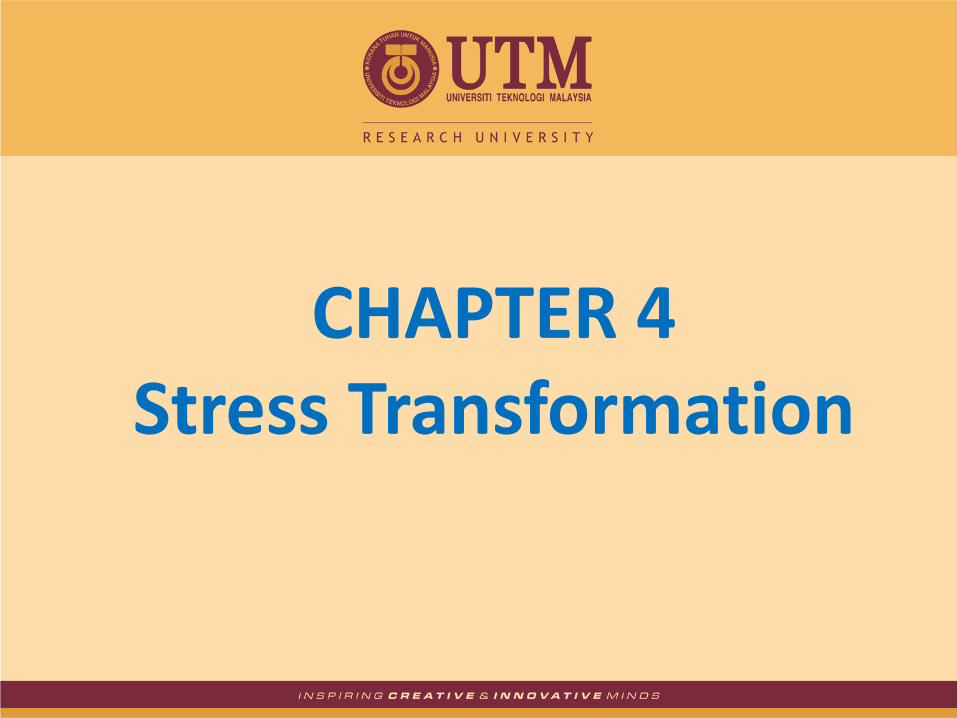
• On plane a-a, normal force, N produces normal stress.
• On plane b-b, normal force, N produces normal stress and shear force, V produces shearing stress.
ANALYSIS OF STRESS
P P
N = P cos
V = P sin
Area = A/cos
𝜎 =𝑁
𝐴=
𝑃
𝐴

ANALYSIS OF STRESS
𝜎𝑛 =𝑃 𝑐𝑜𝑠𝜃
𝐴𝑐𝑜𝑠𝜃
=𝑃
𝐴 𝑐𝑜𝑠2𝜃 = 𝜎𝑥 𝑐𝑜𝑠2𝜃
𝜏 =𝑃 𝑠𝑖𝑛𝜃
𝐴𝑐𝑜𝑠𝜃
= −𝑃
𝐴 𝑠𝑖𝑛𝜃 𝑐𝑜𝑠𝜃 = −𝜎𝑥 𝑠𝑖𝑛𝜃 𝑐𝑜𝑠𝜃
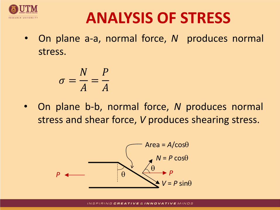
• On an element, there are 6 components of stress: x , y , z , xy , yz , and zx
• If the z axis is not considered or the stresses are independent with the z axis, then there exist only stresses in the x and y directions.
x z
y
ANALYSIS OF STRESS

• This state of 2-dimensional stress is known as plane stress.
z = xz = yz = 0
All directions shown (axes and on element) are taken as positive.
x
y’ y x’
x
a
a
y
x
y
xy
ANALYSIS OF STRESS UNDER 2D

• Stresses on an element can be transformed using 2 methods:
(i) Equations Method
(ii) Mohr Circle
STRESS TRANSFORMATION

i) Equations Method
• Consider an element rotated an amount of about the z-axis.
• Stresses on an inclined plane will be yielded and can be expressed in terms of x , y , xy and .
STRESS TRANSFORMATION
x
y’
A sin
y
x’ x’y’
xy
x
x’
xy (A sin) cos
A A cos

Sign Convention:
Positive if counter-clockwise and usually taken from the vertical surface (x-plane) to the intended plane
Positive if tension or in the direction of positive axis
Positive if in the direction of positive shear (counter-clockwise) xy = yx
STRESS TRANSFORMATION
+xy
+y
+x

Normal Stress:
Shear Stress:
Note: If is clockwise, then put a negative sign in the equation(s)
STRESS TRANSFORMATION
𝜎𝑥′ =𝜎𝑥 + 𝜎𝑦
2+
𝜎𝑥 − 𝜎𝑦
2 𝑐𝑜𝑠2𝜃 + 𝜏𝑥𝑦 𝑠𝑖𝑛2𝜃
𝜎𝑦′ =𝜎𝑥 + 𝜎𝑦
2−
𝜎𝑥 − 𝜎𝑦
2 𝑐𝑜𝑠2𝜃 − 𝜏𝑥𝑦 𝑠𝑖𝑛2𝜃
𝜏𝑥′𝑦′ = −𝜎𝑥 − 𝜎𝑦
2𝑠𝑖𝑛2𝜃 + 𝜏𝑥𝑦 𝑐𝑜𝑠2𝜃
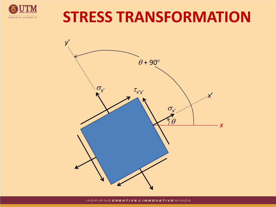
STRESS TRANSFORMATION
x
x’
y’
x’
y’ x’y’
+ 90
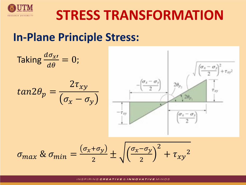
In-Plane Principle Stress:
STRESS TRANSFORMATION
Taking 𝑑𝜎𝑥′
𝑑𝜃= 0;
𝑡𝑎𝑛2𝜃𝑝 =2𝜏𝑥𝑦
𝜎𝑥 − 𝜎𝑦
𝜎𝑚𝑎𝑥 & 𝜎𝑚𝑖𝑛 =𝜎𝑥+𝜎𝑦
2±
𝜎𝑥−𝜎𝑦
2
2+ 𝜏𝑥𝑦
2

Maximum In-Plane Shear Stress:
STRESS TRANSFORMATION
Taking 𝑑𝜏
𝑥′𝑦′
𝑑𝜃= 0;
𝑡𝑎𝑛2𝜃𝑠 = −𝜎𝑥 − 𝜎𝑦
2𝜏𝑥𝑦
𝜏𝑚𝑎𝑥 & 𝜏𝑚𝑖𝑛 = ±𝜎𝑥−𝜎𝑦
2
2+ 𝜏𝑥𝑦
2

Average Normal Stress:
When substituting the values for 2s into the equation for normal stress (σx’), there is also a normal stress on the plane of maximum in-plane shear stress, which can be determined by:
STRESS TRANSFORMATION
𝜎𝑎𝑣𝑔 =𝜎𝑥 + 𝜎𝑦
2

The state of plane stress at a point on a body is shown on the element in the Figure. Represent this stress state in terms of the principal stresses.
EXAMPLE 1
x
y
20 MPa
90 MPa
60 MPa
xy
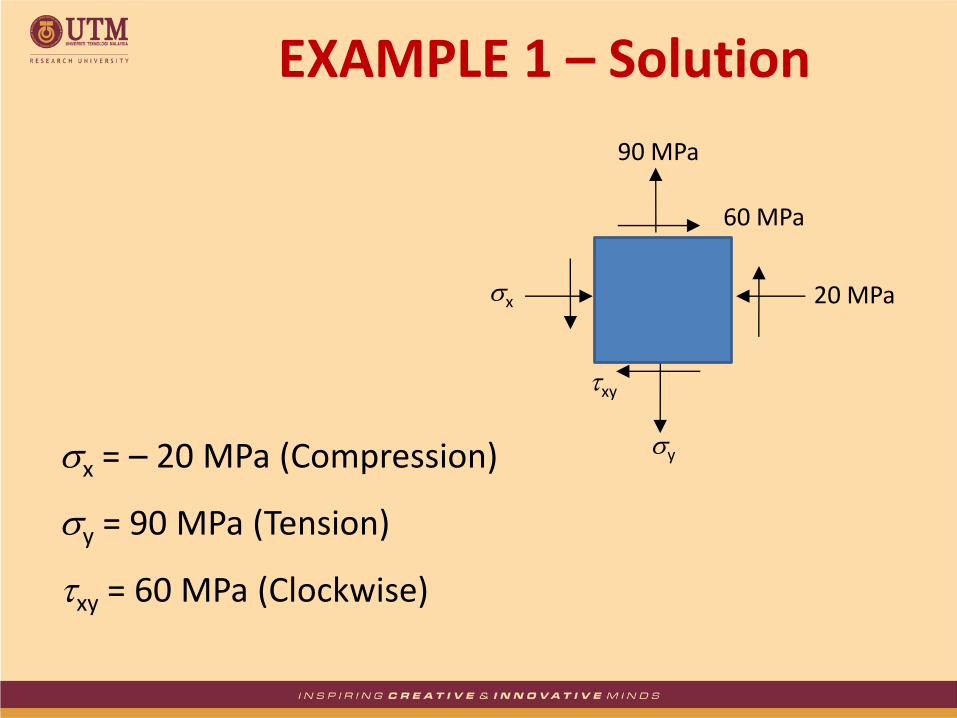
x = – 20 MPa (Compression)
y = 90 MPa (Tension)
xy = 60 MPa (Clockwise)
EXAMPLE 1 – Solution
x
y
20 MPa
90 MPa
60 MPa
xy

Principal Stresses
EXAMPLE 1 – Solution
𝜎𝑚𝑎𝑥 & 𝜎𝑚𝑖𝑛 =𝜎𝑥 + 𝜎𝑦
2±
𝜎𝑥 − 𝜎𝑦
2
2
+ 𝜏𝑥𝑦2
𝜎𝑚𝑎𝑥 & 𝜎𝑚𝑖𝑛 =−20 + 90
2±
−20 − 90
2
2
+ 602
𝜎𝑚𝑎𝑥 & 𝜎𝑚𝑖𝑛 = 35 ± 81.4 max = 35 + 81.4 = 116 MPa min = 35 – 81.4 = 46.4 MPa

Orientation of Element
EXAMPLE 1 – Solution
𝑡𝑎𝑛2𝜃𝑝 =2𝜏𝑥𝑦
𝜎𝑥 − 𝜎𝑦
𝑡𝑎𝑛2𝜃𝑝 =2 × 60
−20 − 90
2p2 = 47.49 p2 = 23.7 2p1 = 47.49 + 180 = 132.51 p1 = 66.3

The principal plane on which each normal stress acts can be determined by applying:
𝜎𝑥′ =𝜎𝑥 + 𝜎𝑦
2+
𝜎𝑥 − 𝜎𝑦
2 𝑐𝑜𝑠2𝜃 + 𝜏𝑥𝑦 𝑠𝑖𝑛2𝜃
𝜎𝑥′ =−20 + 90
2+
−20 − 90
2 𝑐𝑜𝑠 −47.49° + 60𝑠𝑖𝑛 −47.49°
x’ = 46.4 MPa
Hence, σmin = 46.4 MPa acts on the plane defined by θp2 = 23.7°, whereas σmax = 116 MPa acts on the plane defined by θp1 = 66.3°.
EXAMPLE 1 – Solution

By replacing the θp1 and θp2 into the equation for shear stress:
𝜏𝑥′𝑦′ = −𝜎𝑥 − 𝜎𝑦
2𝑠𝑖𝑛2𝜃 + 𝜏𝑥𝑦 𝑐𝑜𝑠2𝜃
𝜏𝑥′𝑦′ = −−20 − 90
2𝑠𝑖𝑛 −47.49° + 𝜏𝑥𝑦 𝑐𝑜𝑠 −47.49°
x’y’ = 0 MPa
No shear stress acts on this element.
EXAMPLE 1 – Solution

The state of plane stress at a point on a body is represented on the element shown in the Figure. Represent this stress state in terms of the maximum in-plane shear stress and associated average normal stress.
EXAMPLE 2
x
y
20 MPa
90 MPa
60 MPa
xy

Maximum In-Plane Shear Stresses
MPa
xy
yx
4.81
602
9020
2
max
2
2
max
2
2
max
EXAMPLE 2 – Solution

Orientation of Element
3.111
5.2225.421802
3.21
5.422
602
90202tan
22tan
1
1
2
2
s
s
s
s
s
xy
yx
s
EXAMPLE 2 – Solution

The proper direction of max on the element can be determined by applying the equation:
MPayx
yx
xy
yx
yx
4.81
5.42cos605.42sin2
9020
2cos2sin2
''
''
''
EXAMPLE 2 – Solution

Average Normal Stress Besides the maximum shear stress, as calculated above, the element is also subjected to an average normal stress determined from the equation:
MPaavg
avg
yx
avg
35
2
9020
2
EXAMPLE 2 – Solution
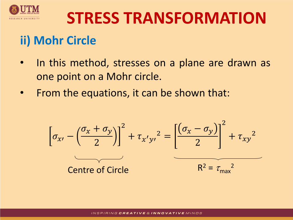
ii) Mohr Circle
• In this method, stresses on a plane are drawn as one point on a Mohr circle.
• From the equations, it can be shown that:
Centre of Circle R2 = max2
STRESS TRANSFORMATION
𝜎𝑥′ −𝜎𝑥 + 𝜎𝑦
2
2
+ 𝜏𝑥′𝑦′2 =
𝜎𝑥 − 𝜎𝑦
2
2
+ 𝜏𝑥𝑦2

Steps for constructing Mohr Circle: 1. Determine centre of circle, C (x, y)
x = avg , y = 0
2. Determine point A (x, xy) : coordinate when = 0
x = +ve (tension) or –ve (comp)
xy = +ve (counter clockwise) or –ve (clockwise)
3. Determine point A’ (y, yx) : coordinate when = 90
4. Draw circle connecting A and A’ with C as the centre
5. The datum (reference line) in Mohr circle is line AC
6. All angles must be determined from line AC ( = 0)
STRESS TRANSFORMATION
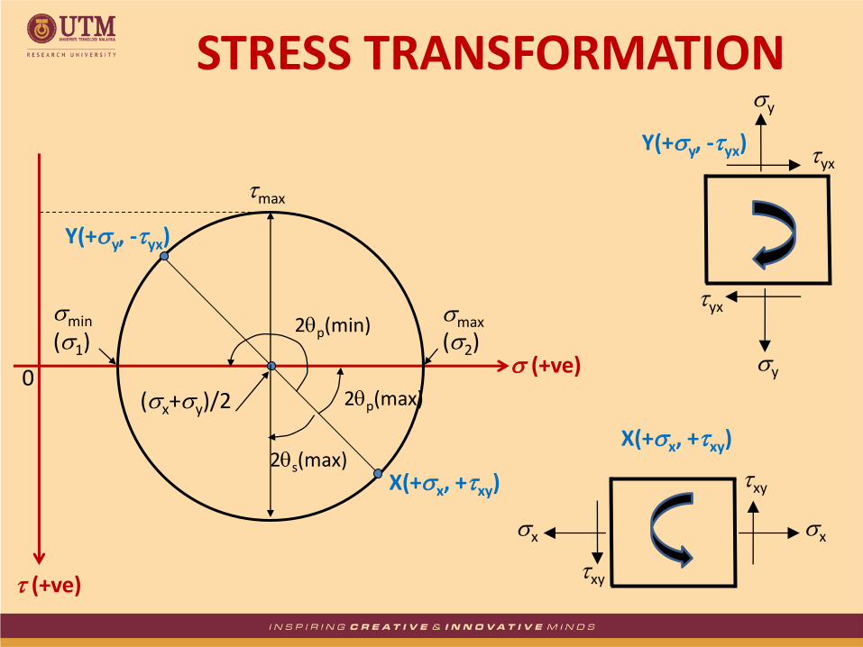
max
0
min (1)
(+ve)
(x+y)/2
(+ve)
max
(2)
2p(max)
2p(min)
y
y
yx
yx
Y(+y, -yx)
x x
xy
xy
X(+x, +xy) 2s(max)
STRESS TRANSFORMATION
X(+x, +xy)
Y(+y, -yx)

The state of plane stress at a point on a body is represented on the element shown in the Figure. Determine the principal stresses and the orientation acting at this point.
EXAMPLE 3
x
y
20 MPa
90 MPa
60 MPa
xy

Construction of the Circle
x = –20 MPa (Compression)
y = 90 MPa (Tension)
τxy = 60 MPa (Clockwise)
EXAMPLE 3 – Solution
The Centre of Circle is at:
The Radius of the Circle is:
𝜎𝑎𝑣𝑔 =𝜎𝑥 + 𝜎𝑦
2=
−20 + 90
2= 35 𝑀𝑃𝑎
𝑅 =𝜎𝑥 − 𝜎𝑦
2
2
+ 𝜏𝑥𝑦2 =
−20 − 90
2
2
+ 602 = 81.4 𝑀𝑃𝑎
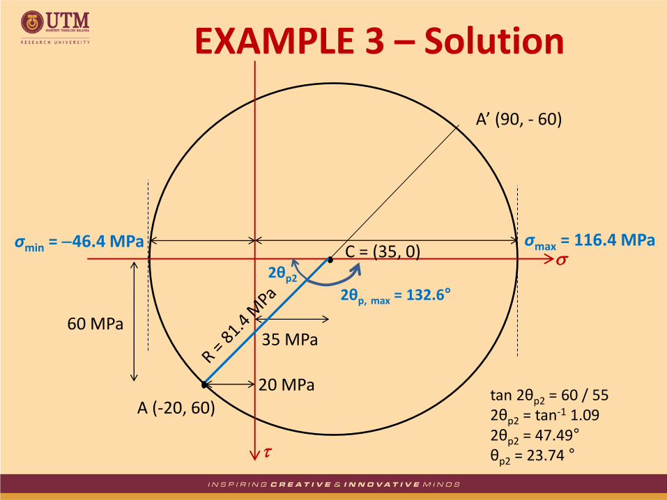
tan 2θp2 = 60 / 55 2θp2 = tan-1 1.09 2θp2 = 47.49° θp2 = 23.74 °
EXAMPLE 3 – Solution
35 MPa
20 MPa
60 MPa
σmax = 116.4 MPa σmin = 46.4 MPa
2θp, max = 132.6°
A (-20, 60)
A’ (90, - 60)
C = (35, 0) 2θp2

The state of plane stress at a point on a body is represented on the element shown in the Figure. Determine the maximum in-plane shear stresses and the orientation of the element upon which they act.
EXAMPLE 4
x
y
20 MPa
90 MPa
60 MPa
xy

tan 2θs1 = 55 / 60 2θs1 = tan-1 1.09 2θs1 = 42.5° θs1 = 21.3 °
EXAMPLE 4 – Solution
35 MPa
20 MPa
τmax = 81.4MPa
2θs1 = 42.5°
τmin = 81.4MPa
A’ (90,- 60)
A (-20, 60)

EXAMPLE 4 – Solution
81.4 MPa x’
y’
x
35 MPa 21.3

The state of plane stress at a point on a body is represented on the element shown in the Figure. Represent this state of stress on an element oriented 30° counterclockwise from the position shown.
EXAMPLE 5
x
y
20 MPa
90 MPa
60 MPa
xy

tan 2θ = 55 / 60 2θ = tan-1 1.09 2θ = 42.5° θ = 21.3 °
= 60° – 42.5° = 17.5 °
At Point B:
x’ = 35 + 81.4 sin17.5°
x’ = 59.48 MPa
x’y’ = 81.4 cos 17.5°
x’y’ = 77.63 MPa
EXAMPLE 5 – Solution
35 MPa 20 MPa
42.5°
A (-20, 60)
= 17.5°
x’
x’y’
B’
B
C

EXAMPLE 5 – Solution
35 MPa 20 MPa
42.5°
A (-20, 60)
= 17.5°
x’
x’y’
B’
B
C
x’y’
x’
= 17.5°
At Point B’:
y’ = 81.4 sin 17.5° 35
y’ = 10.52 MPa
x’y’ = 81.4 cos 17.5°
x’y’ = 77.63 MPa

EXAMPLE 5 – Solution
x’
y’
x 30

An element is subjected to the plane stresses shown in the figure. (a) Determine normal stress and shear stress acting
on the plane that is inclined at 20o as shown in the figure.
(b) Determine the maximum normal stress and its orientation.
(c) Sketch the plane of the maximum normal stress by showing its values and orientation.
(d) Determine the maximum shear stress.
30 N/mm2
30 N/mm2
50 N/mm2
50 N/mm2
20o
CLASS EXERCISE