Embed Size (px)
Citation preview
8/8/2019 Chapter 4-Second Edition
http://slidepdf.com/reader/full/chapter-4-second-edition 1/29
Introduction to Telecommunications by Gokhale
CHAPTER 4
VOICE
COMMUNICATIONS
8/8/2019 Chapter 4-Second Edition
http://slidepdf.com/reader/full/chapter-4-second-edition 2/29
2
PSTN Public Switched Telephone Network
± Based on star, ring or mesh topologies
± Consists of transmission paths and nodes
± Originally designed to carry voice but being used more
and more to carry data
Nodes
± Exchange or switching points where two or more paths
meet, enabling the users to share transmission paths
8/8/2019 Chapter 4-Second Edition
http://slidepdf.com/reader/full/chapter-4-second-edition 3/29
3
Switching
Switch
± Sets up a communication path on demand and takesit down when it is no longer needed
Switching
± Routing information to different parties
8/8/2019 Chapter 4-Second Edition
http://slidepdf.com/reader/full/chapter-4-second-edition 4/29
4
Switching System Components Switching matrix
Controller Database
Line circuits
Trunk circuits
Common equipment
8/8/2019 Chapter 4-Second Edition
http://slidepdf.com/reader/full/chapter-4-second-edition 5/29
5
Characteristics of Switching Systems Blocking networks
± Older networks with fewer paths than terminations
so all users cannot be served simultaneously
Non-blocking networks
± Enable a connection independently of the amountof traffic
Virtually non-blocking networks
± Compromise between blocking and non-blockingnetworks
8/8/2019 Chapter 4-Second Edition
http://slidepdf.com/reader/full/chapter-4-second-edition 6/29
6
K ey Terms in Switching Systems
Common control systems ± Translation of the telephone number, automatic call routing,
digit conversions, and trunk signaling
Direct control systems ± Lack alternate routing and digit translation capabilities
Virtually non-blocking ± Not totally non-blocking but provides enough paths so users
are rarely blocked
Busy Hour Call Attempts (BHCA) ± The number of calls the system can handle during peak hour
Concentration or line-to-trunk ratio ± Determines the probability that a call will be completed
8/8/2019 Chapter 4-Second Edition
http://slidepdf.com/reader/full/chapter-4-second-edition 7/29
7
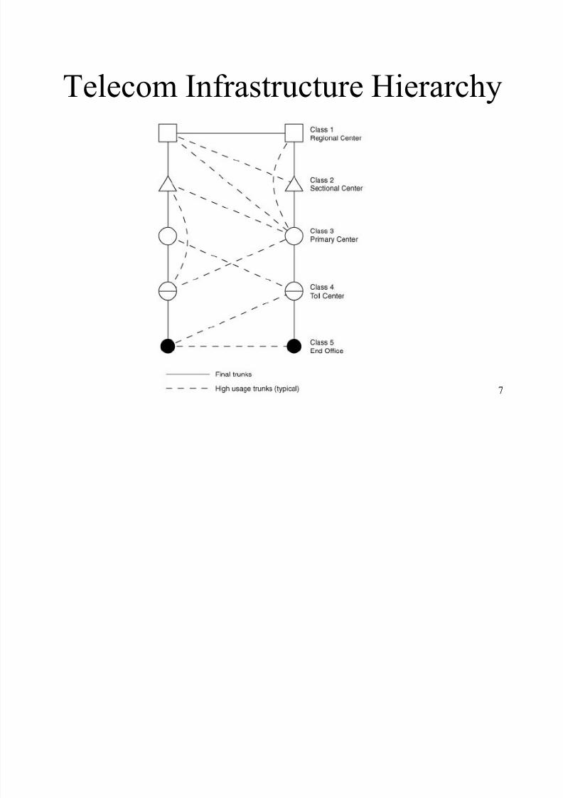
Telecom Infrastructure Hierarchy
8/8/2019 Chapter 4-Second Edition
http://slidepdf.com/reader/full/chapter-4-second-edition 8/29
8
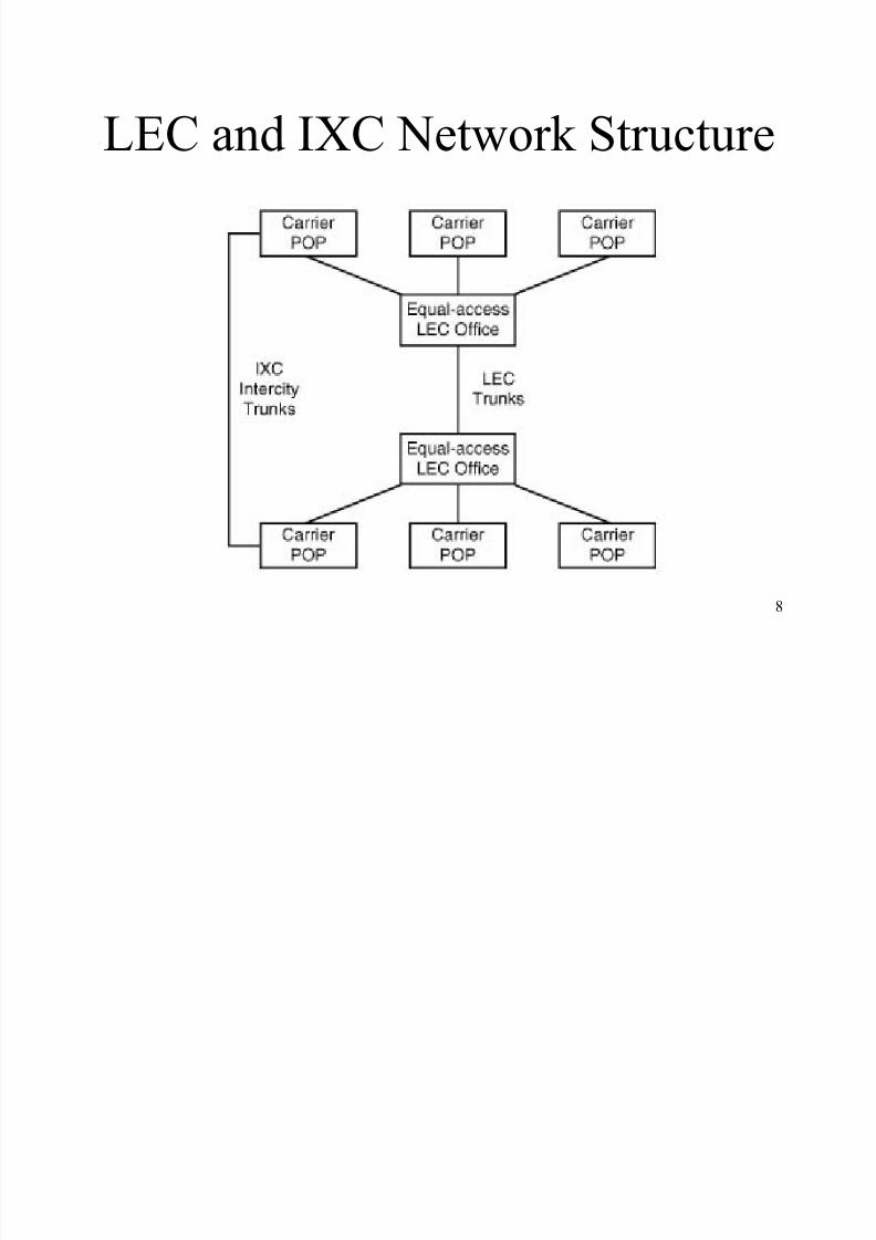
LEC and IXC Network Structure
8/8/2019 Chapter 4-Second Edition
http://slidepdf.com/reader/full/chapter-4-second-edition 9/29
9
Telephone Cable Architecture
Telephone Cable Hierarchy
± Trunks (in North America, that are same as³Junctions´ in Europe)
High-speed digital carriers that interconnect nodes
± Feeders
± Branch Feeders
± Station Drops (local loops, subscriber lines)
One pair of UTP wire that is usually analog
8/8/2019 Chapter 4-Second Edition
http://slidepdf.com/reader/full/chapter-4-second-edition 10/29
10
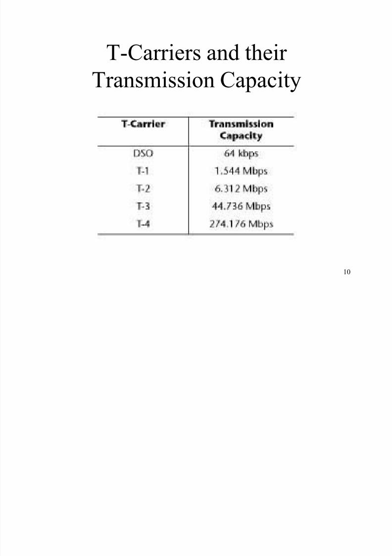
T-Carriers and their
Transmission Capacity
8/8/2019 Chapter 4-Second Edition
http://slidepdf.com/reader/full/chapter-4-second-edition 11/29
11
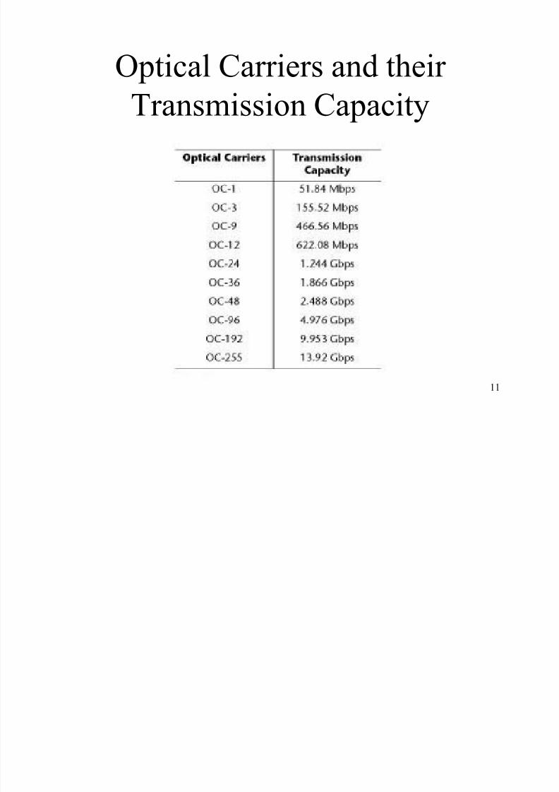
Optical Carriers and their
Transmission Capacity
8/8/2019 Chapter 4-Second Edition
http://slidepdf.com/reader/full/chapter-4-second-edition 12/29
12
Line Conditioning Line Conditioning
± Is used to tighten telephone company parameters so that
they can transfer data at higher speed with reduced
errors
Propagation delay
± Time taken by a signal to travel from source to
destination and ³envelope delay distortion´ measures
the variance in propagation delay within the voice band
Attenuation distortion
± Gain fluctuations with frequency
8/8/2019 Chapter 4-Second Edition
http://slidepdf.com/reader/full/chapter-4-second-edition 13/29
13
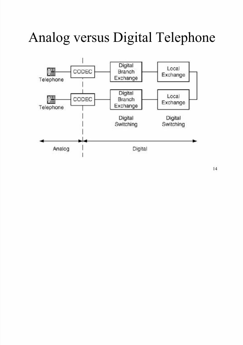
Analog versus Digital Telephone Distinction between the analog versus
digital telephone is where the Codec is
located.
± If it is inside the telephone, it is digital.
± If the Codec is in the telephone company¶s
equipment, the telephone is analog.
8/8/2019 Chapter 4-Second Edition
http://slidepdf.com/reader/full/chapter-4-second-edition 14/29
14
Analog versus Digital Telephone
8/8/2019 Chapter 4-Second Edition
http://slidepdf.com/reader/full/chapter-4-second-edition 15/29
15
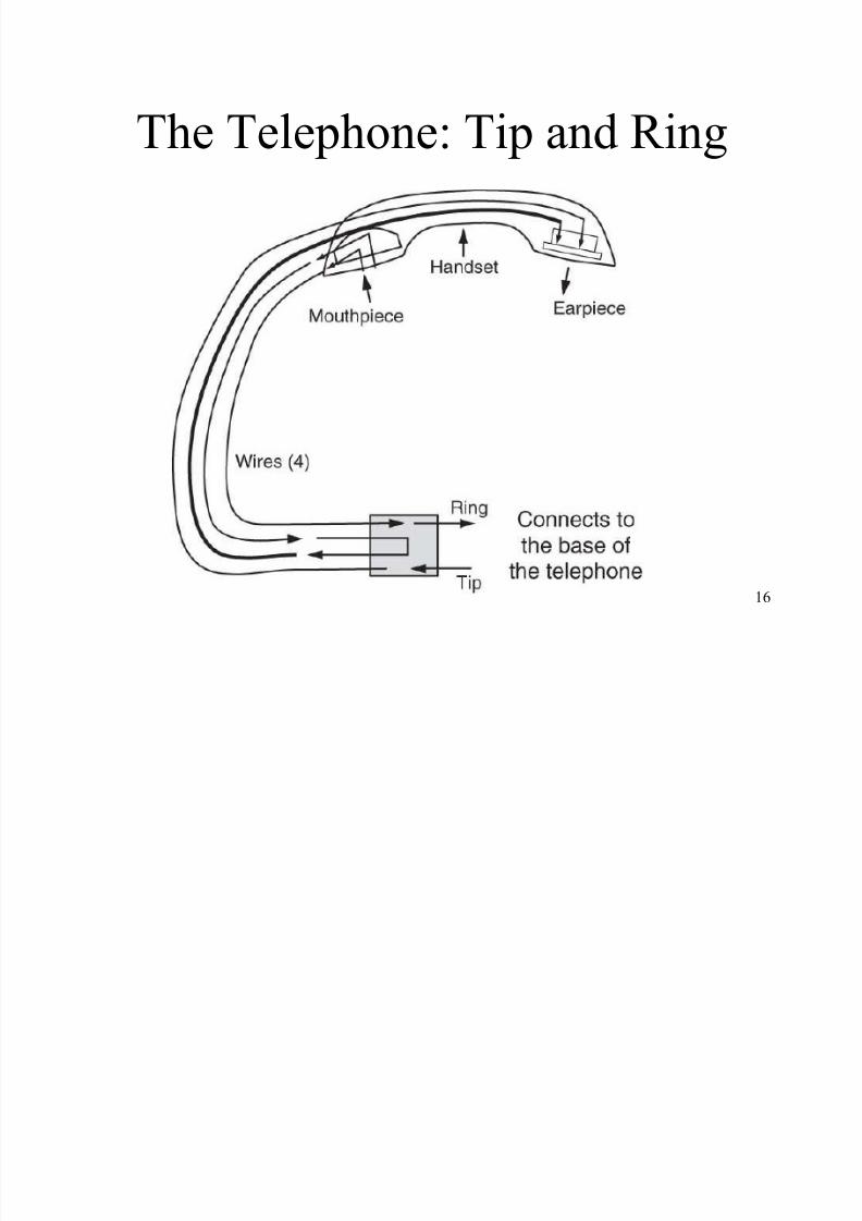
The Telephone Telephony
± Science of translating sound into
electrical signals
Tip and Ring
± Transmit and Receive wire that connect
the instrument to a plug in the wallusing RJ-11 jack
8/8/2019 Chapter 4-Second Edition
http://slidepdf.com/reader/full/chapter-4-second-edition 16/29
16
The Telephone: Tip and Ring
8/8/2019 Chapter 4-Second Edition
http://slidepdf.com/reader/full/chapter-4-second-edition 17/29
17
Outgoing Call Pulse Dial
± In general, pulse repetition rate is between8 and 11 pulses per second (pps)
Dual Tone Multiple Frequency (DTMF) ± Most commonly used signaling system today
± More reliable and faster than ³pulse dial´
± Transmission rate is 7 digits per second
± Consists of a frequency matrix
Multi-Frequency (MF)
± Used on trunk circuits
± Transmission rate is 7 digits per second
8/8/2019 Chapter 4-Second Edition
http://slidepdf.com/reader/full/chapter-4-second-edition 18/29
18
Incoming Call Ringer Equivalence Number (REN)
± Is used to ensure that the local exchange can
provide the correct amount of power required to
ring the telephone
The Ring voltage is about 90 to 105 volts AC
with a frequency of 20 Hz The ±48 volts DC that is always on the line
operates the telephone when it is being used
8/8/2019 Chapter 4-Second Edition
http://slidepdf.com/reader/full/chapter-4-second-edition 19/29
19
Line Signaling: Loop Start Current flows only when the phone is off-hook
Local exchange senses that and provides a dial
tone No need for accurate ground references betweenthe local exchange (remote end) and the telephone(local end)
Tip and Ring wires may be reverse
Problem of ³glare´ (when both the local end andthe remote end attempt to access the circuit at thesame time)
8/8/2019 Chapter 4-Second Edition
http://slidepdf.com/reader/full/chapter-4-second-edition 20/29
20
Line Signaling: Ground Start Usually used only on trunks and PBXs
Minimizes the possibility of ³glare´
Tip and Ring wires cannot be reversed
Local end and remote end must be at the
same potential
8/8/2019 Chapter 4-Second Edition
http://slidepdf.com/reader/full/chapter-4-second-edition 21/29
21
Trunk Signaling Out-of-band
± Separate network to pass call setup, charging, and
supervision information In-band
± Carries call setup, charging, and supervisioninformation over the same circuit
Advantages of out-of-band over in-band
± Lower susceptibility to fraud
± Lower setup time
± Capable of supporting virtual networks
8/8/2019 Chapter 4-Second Edition
http://slidepdf.com/reader/full/chapter-4-second-edition 22/29
22
In-band Signaling Methods Single Frequency
± Most common in-band analog signaling system
± Idle or busy status indicated by the presence or absenceof a 2600 Hz tone in the U.S.
E&M Signaling (recEive and transMit)
± Used on digital four-wire circuits
± Type I: Common in North America
± Type II: Usually on Centrex circuits
± Type V: Most popular outside North America
8/8/2019 Chapter 4-Second Edition
http://slidepdf.com/reader/full/chapter-4-second-edition 23/29
23
Out-of-band Signaling Method Common Channel Signaling
± Most common out-of-band signaling system
Signaling System Seven (SS7) Standard
± HDLC-based protocol developed by CCITT ± Uses layered protocol that resembles the OSI model
± Message Transfer Part of SS7 (bottom three layers of
OSI) Telephony User Part (top four layers of OSI)
± Components: Service Switching Point (SSP) or Action Control Point (ACP)
Signal Transfer Point (STP)
Service Control Point (SCP) or Network Control Point (NCP)
8/8/2019 Chapter 4-Second Edition
http://slidepdf.com/reader/full/chapter-4-second-edition 24/29
2
4
Intelligent Network Services
Caller Identification
Automatic Call Distribution (ACD)
± Distributes calls evenly among multiple agents Voice processing systems
± Interactive Voice Response (IVR)
Example: Users selecting an option using voice
± Automated Attendant or Auto Answer (AA) Example: Automatic greeting followed by ACD
± Voice mail
Example: Electronic mailbox
8/8/2019 Chapter 4-Second Edition
http://slidepdf.com/reader/full/chapter-4-second-edition 25/29
25
Different Types of Telephone Lines ISDN line: All-digital transmission line
T-1 line: Digital high-capacity phone line
Tie trunk: Point-to-point connection DID (Direct Inward Dial) line: Dials extensions
directly without the intervention of an operator
DOD (Direct Outward Dial) line: Uses an access code
FX circuit: Provides users with a local telephonenumber for a remote location
Toll free line: Reverse billing service
8/8/2019 Chapter 4-Second Edition
http://slidepdf.com/reader/full/chapter-4-second-edition 26/29
26
PBX Private Branch Exchange (PBX)
± Popular choice for large businesses
± Enables switching of in-house calls
± Much less expensive than connecting an
external line to every telephone
± Provides centralized support such as voice mail ± Highly reliable but they are big, expensive, and
difficult to configure
8/8/2019 Chapter 4-Second Edition
http://slidepdf.com/reader/full/chapter-4-second-edition 27/29
27
Centrex Centrex (Central Office Exchange Service)
± Popular choice for small-to-medium sized
businesses because it provides the features of aPBX without having to buy one
± Service offered by the telephone companywhere most of the equipment resides
± Special circuit called Station Message DetailInterface (SMDI) links the local exchange tothe Centrex customer
8/8/2019 Chapter 4-Second Edition
http://slidepdf.com/reader/full/chapter-4-second-edition 28/29
28
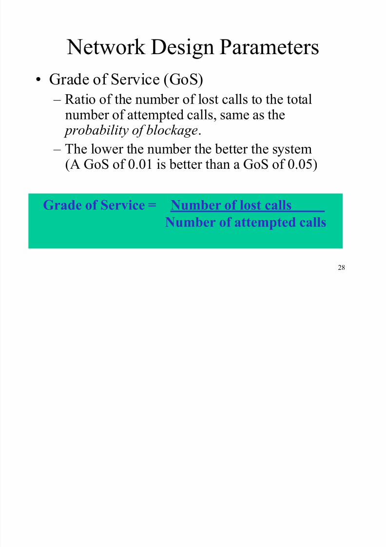
Network Design Parameters
Grade of Service (GoS)
± Ratio of the number of lost calls to the totalnumber of attempted calls, same as the
pr obability of blockage. ± The lower the number the better the system
(A GoS of 0.01 is better than a GoS of 0.05)
Grade of Service = Number of lost callsNumber of attempted calls
8/8/2019 Chapter 4-Second Edition
http://slidepdf.com/reader/full/chapter-4-second-edition 29/29
29
Network Design Parameters
continued«
Estimated Traffic
± Traffic is the term that quantifies usage. Usageor total t r affic intensity is measured in centi-callseconds (CCS) = 100 call seconds of traffic inone hour. 36 CCS = 100% utilization
Network Design
± Trade-off between cost and quality of service
± Optimum designs: cost-savings whilemaintaining quality