Embed Size (px)
Citation preview

45
CHAPTER 4
REACTOR STATICS
The study of a nuclear reactor operating in a steady-state is termed reactorstatics; both short and long time variations represent dynamic characteristicsand will be discussed in the next chapters. Our description here will focus oncertain reactor core parameters such as neutron multiplication and on somebasic spatial distributions such as the neutron flux.
4.1 REACTOR CRITICALITY
We begin our analysis of the reactor core with a description of the neutroninduced fission process. In Fig. 4.1 we show graphically some of the eventswhich lead to the steady-state condition in a CANDU nuclear reactor. A slowor thermal neutron, possessing a speed of approximately 2200 mis, is absorbedin a Uranium-235 nucleus. This Uranium-236 nucleus subsequently breaks up intotwo fission fragments of unequal mass and concurrently emits several high energyneutrons whose energies are in the MeV range. These high energy neutrons subsequently migrate through the reactor core and, in doing so, may undergo anumber of reactions; for example, they may become absorbed in the structuralmaterial in the core or even escape from the reactor core entirely. The oneprocess of partiCUlar importance to the CANDU reactor is that the neutron losesits large kinetic energy by elastic collision predominantly in the heavy watermoderator. Once the neutron has attained a relative low kinetic energy it ismote likely to induce fission in Uranium-235 and thus contribute to the maintenance of the chain reaction. Such a sequence of events represents a life-historyof a neutron and may be viewed as one generation. The time required for thiscycle is relatively short, about 0.001 s; the path traced out by a neutronduring its life-history may very well exceed several meters.
Several pertinent questions come to mind when considering the above sequence ofevents. How is it possible to insure that for everyone neutron which causesfission exactly one neutron will cause a subsequent fission in order that asteady-state chain reaction can be maintained? How is the chain reaction influenced by the material composition of the core ann hy the ~ize of the reactor?What is the role of the neutron density and what is the effect of fission products?Some of the answers to these questions will become clear forthwith while otherswill be discussed in subsequent chapters.
46
uranium235.e
slownputron
HEAv¥=W"MEFl__Jli!fllIIfKt1TIIK--
e/e
.STAGE IVSTAGE III
he;:e~•fission
•fissionproduct
fissionproduct
STAGE II._-_.----_.. '-
235uraniume
STAGE I
•"putronslow
FIG. 4.1: Illustration of fission chain reaction and subsequent events.
One parameter which has become widely used in the analysis of nuclear reactorsis called the effective multiplication constant and identified by the symbolkeff' This parameter represents the ratio of neutrons of two successive generations in a finite reactor. That is
(4.1)Number of neutrons in a subsequent generationkeff = ....--,.......:.-'--,;--'-'-=-'-'-:--'-..::..;.;..=---.;.-'-'--';,--:--'-----'--'-'1-.---"-------;-;,-Number of neutrons in the preceding generation
Clearly, if keff = 1, a steady-state condition exists because the neutron population does not change with time. If keff > 1 then the neutron density isincreasing with time and, since the reactor power varies with the number ofneutrons causing fission, the reactor power increases with time; such a situationexists during reactor start-up .. If keff < 1 then the fission rate decreaseswith time since the neutron density decreases. These effects are graphicallyillustrated in Fig. 4.2.
The above description suggests an effective method of reactor control: it isa matter of controlling the number of neutrons in the reactor. If the reactorpower is to be decreased or if the reactor is to be shut down, then controlrods containing strong neutron absorbing materials are inserted into the core;the neutrons absorbed in the control rod thus contribute to a neutron deficiencyin the core resulting in a decrease in the fission rate. Withdrawal of thecontrol rods has the reverse effect. Other possibilities such as neutron boosterrods and moderator level variation may also be employed in reactor control andwill be discussed in subsequent chapters.

C't':W
~o0.
ex:olt.)
<rwex:
r-------------
TIME
------,i
47
FIG_ 4.2: Variation of reactor power with time for different values of theeffective multiplication constant keff .
We now consider some of the reaction processes which effect the number of neutronsin successive generation to permit a quantitative representation for keff. Thenumerical values chosen here for the various parameters will be those whichapproximately apply to the CANDU reactor.
1. Initi a1 Conditi onWe suppose that initially 100 neutrons appear in a given neutron
generation as a result of the fission processes. That is, the denominator in Eq. (4.1) is 100; we now wish to follow these 100 neutronsthrough a complete cycle and thus determine the expression for thenumerator in Eq. (4.1).
2. Fast FissionBefore these 100 neutrons have a chance to slow down, several
of these high energy neutrons. say 2, may cause fission in twoUranium-238 nuclei; supposing that in one fission we have 3 fissionneutrons appearing while in the other 2. Thus, the number of neutronshas increased to 103. This effect is called the fast fission effectand is described by the fast fission factor, E, which, in this case,has the value
E = (100 - z) + 5 =100 1.03 (4.2)
3. Fast Neutron LeakageSince these 103 neutrons possess a relatively high energy their

48
path between inter'dctions wi th nuclei is very ldrge. Hence, some ofthese neutrons may escape entirely from the reactor core. Supposingthat 4 neutrons escape; this now leaves 103 - 4 = 99 neutrons of theoriginal 100. This effect is called the fast non-leakage probability,PF, and is given by
(4.3)
4. Resonance Escape ProbabilityThe remaining 99 neutrons now undergo a slowing down process
involving primarily elastic scattering in the moderator. However, inthe course of neutron migration. some of these neutrons may encounterisotopes such as Uranium-238 which exhibits very strong resonanceabsorption in the intermediate energy range. Some 10% of the fissionneutrons are absorbed in these resonances leaving 99 - 10 = 89 neutrons.This possibility serves to define the resonance escape probability,p, which in this case, has the value of
p = 9999 10 = 0.899 . (4.4)
5. Thermal UtilizationNow that 89 of the original 100 neutrons have reached thermal
energy we must recognize that neutron absorption can take place inmaterials other than in the nuclear fuel. Approximately 5 neutronsare removed in this parasitic process leaving 89 - 5 = 84 neutrons.The factor describing this phenomena, designated by, f, and calledthermal utilization, is therefore given by
f = 89 - 5 0 94484 =. . (4.5)
6. Thermal Neutron LeakageIn a manner similar to fast neutron leakage, thermal neutrons may
also leak from the reactor core as well. This may involve some 4neutrons leaving 84 - 4 = 80 neutrons. The appropriate thermal nonleakage probability. PT- is found to be
84 - 484 = 0.952 (4.6)
7. Fission Neutrons per Neutrons AbsorbedHavinq fo110winq the history of 100 neutrons throuqh the various
events we have now arrived at the point where of the orlginal 100neutrons 80 are now absorbed in natural uranium. Not all of theselead to fission because uranium does have a definite parasitic capturecross section. However, the ratio of fission neutrons emitted perthermal neutron absorbed is of the order 1.25; this parameter ;srepresented by the symbol 11:
11 = 1.25 . (4.7)
49
Hence, the number of new fission neutrons resulting from the absorptionof the 80 thermal neutrons is therefore
n x 80 = 1.2~ x 80 = 100 . (4.8)
Thus starting with an initial set of 100 fast fission neutrons, the same numberof neuLrons has been pruduced in the subsequent generation.
The definition for keff may now be cast in quantitative form.steps above we note that the number of neutrons in the secondgiven by the product of the factors enumerated: lOOsPFpfPTn.multiplication constant is hence represented by
Retracing ourgeneration isThe effective
(4.9)
where the factor 100 has been cancelled in the numerator and denominator. Thatis. keff is independent of the number of initial neutrons and hence is noteffected by power level.
The first four factors in Eq. (4.9) - often called the four-factor-formula is the multiplication constant appropriate for a reactor of infinite size andrepresented by
(4.10)
The product PFPT accounts for fast and thermal leakage associated with reactorsof finite size. We may therefore write
(4.11)
where P represents the probability that neither a slow nor a fast neutronwill escape from the reactor.
The neutron cycle, as discussed above, is illustrated graphically in Fig. 4.3.
4.2 APPROACH TO CRITICAL
In the preceding section we described the several processes which are of particular importance to the determination of the state of criticality of a fissileassembly. Each parameter listed in Eq. (4.9) can, in principle, be calculatedfor a given material composition possessing a specified geometric shape. Indeed.these calculations are always carried out to determine the fuel loading of anuclear reactor. This is not to suggest that, based on calculations alone, thereactor core materials are assembled up to the composition specified and thatit is then expected to be exactly critical. Indeed, because of uncertainties

50
in the nuclear processes involved and approximations in the mathematical andcalculational models, it is required practice that an approach to criticalprocedure be employed when the reactor is first made critical.
INITIALFISSIONNEUTRONS
'------------~- --- ---------- ------------ -----'----------------------- ------
FIG. 4.3: Illustration of the neutron cycle; the numerical values listed areapproximate and correspond to the valves used in the text.
The approach to critical can best be described by reference to a graphicalrepresentation. Consider Stage I of Fig. 4.4. This represents the reactor corefully loaded with fuel but containing no moderator. Since any fission neutronswhich might thus appear - either as a result of spontaneous fission or inducedby a small isotopic neutron source - will not slow down due to the absence of amoderator, very few thermal neutrons which might cause fission will exist, hencethe reactor is far subcritical.
Now consider the case in which some heavy water moderator has been added. StaqeII in Fig. 4.4. Some neutron moderation is now taking place and, as a consequence,some neutron multiplication is occurring. As more moderator is added, more

FIG. 4.4: Illustration of the approach tocritical. The moderator level is successively raised and the neutron density measuredat each step.
fissions occur and the neutrondensity in the core increases toa new level. Eventually, at somecritical height of the moderator,criticality will occur whichmeans that a strict balanceexists between (l) neutronproduction by fission, (2)neutron removal by absorption,and (3) neutron escape from thereactor by leakage. From hereon, the appropriate managementof control rods provides thenecessary operating mechanism.
The above can be described analytically and thus provide abasis for monitoring the approachto critical. Supposing a neutrondetector were located so as toprovide an indication of an average neutron density in themoderator. If, at a given timeduring the approach to critical,the effective multiplicationconstant was given by keff thenif n number of neutrons areintroduced in the reactor corethey will produce nkeff neutronsin the second generatlon. Thesenk neutrons subsequently leadto (nkeff)keff = nk~ff neutronsin the next generatlon and soon. The neutron density asrecorded by the detector at anymoderator level is given by the infinite
STAGE I
STAGE II
1H
TSTAGE III
TH
1
series
51
S = n + nkeff + nk~ff + nk~ff + ... ,
= n(l + keff + k~ff + k~ff + ... ) . (4.12)
Since the reactor is subcritica1, keff is less than unity and the above seriescan be shown to be written as
S = n( 11 )keff
(4.13)
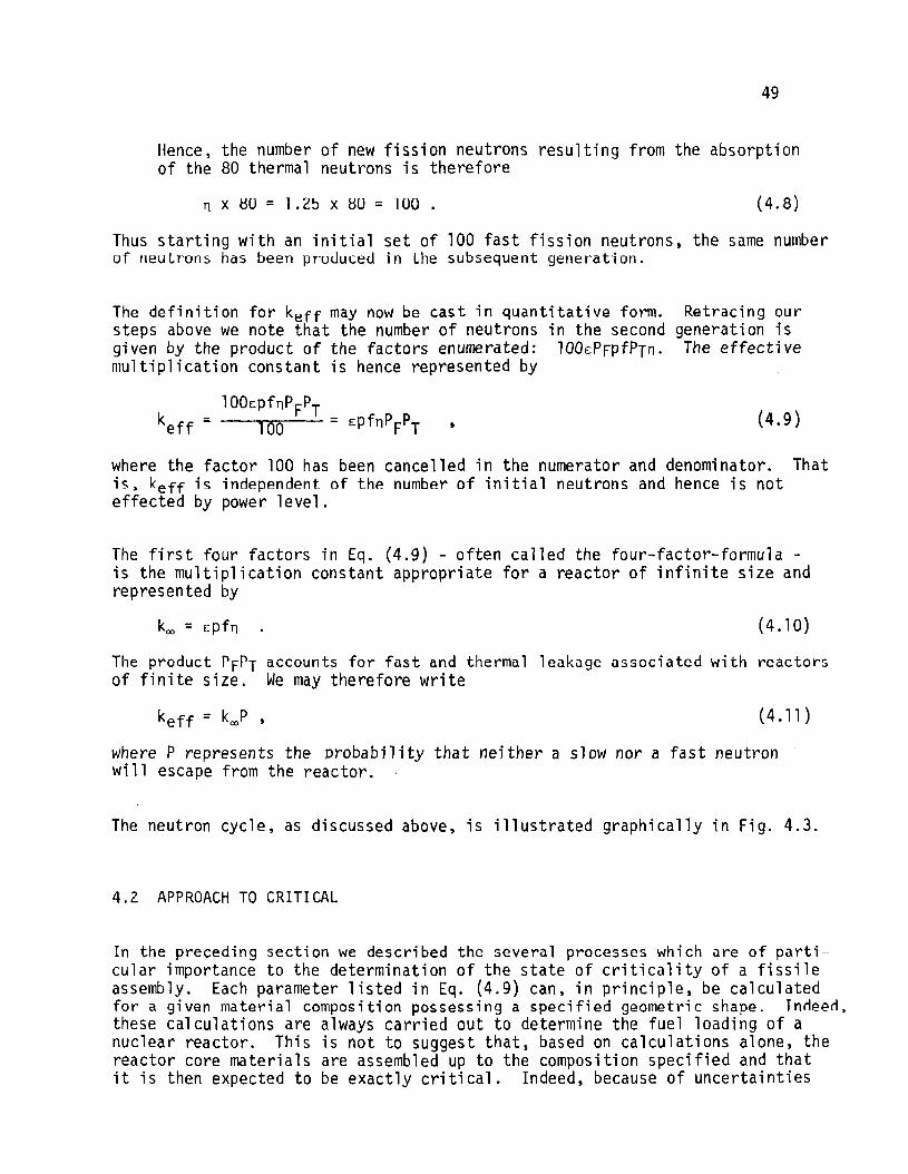
As the moderator level continued to be raised, keff approaches unity and hencethe neutron count rate, S, approaches an increasingly large number. The moderator height at which the reactor is critical is determined by extrapolation the
52
the inverse of the detector count rate, liS, to zero. This is graphicallyshown in Fig. 4.5. Except for emergency dumps and other designed operatingprocedures, the moderator level ;s kept just below this critical height.The control rods arp then us~d to provide overall reactor control. This subject will be further discussed in a subsequent chapter. Of more immediateinterest in the problem of specifying the neutron flux in the reactor core.
MEASURED POINTS x
a:Cltu\.I.Iwt-lWe(Cla:U-lCl~
\.1.1;:)<1)0a:uw>:2
CRITICALMODERATORHEIGHT
MODERATOR HEIGHT, H
FIG. 4.5: Inverse of neutron detector count rate as a function of moderatorhei ght.
4.3 NEUTRON DIfFUSION ANALYSIS
In the preceding sections we have discussed some of the processes which areimportant to the attainment of a steady-state critical condition in a reactorcore. We now consider such a steady-state core from the standpoint of determining the neutron density or the neutron flux density. A knowledge of howthe flux varies in a reactor is important since many of the vital processes,such as fuel burnup, are directly related to the neutron flux.
We recall that the neutron-nucleus interaction density at a point ~ ;n the corefor the i'th type of process may be written
(4.14)
where the symbolism is used as defined previously. Also, in view of our discussion of energy dependence, we assume here that the neutron flux, ~(r) ;ssuitably averaged so that Eq. (4.14) adequately represents the interactiondensity rate (neutrons/cm3-s) at the point!" The above expression may betermed an energy-averaged interaction density.
53
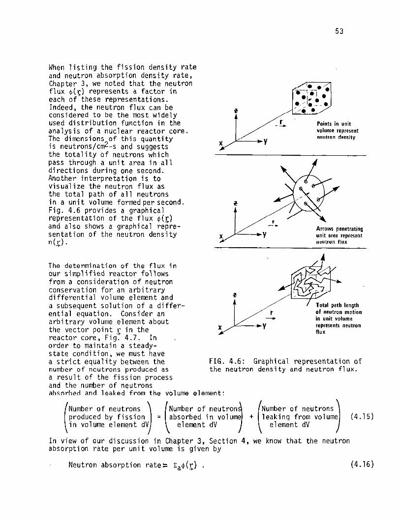
FIG. 4.6: Graphical representation ofthe neutron density and neutron flux.
(4.15)
Points in unitvolume representnl!lJtron density
Arrows penetratingunit area representneulrun flux
Total path lengthof neutron motionin unit volumerepresents neutronflux
r-
(
Number of neutrons1+ leaking from volume
element dV
4, we know that the neutron
x
x
The determination of the flux inour simplified reactor followsfrom a consideration of neutronconservation for an arbitrarydifferential volume element anda subsequent solution of a differential equation. Consider anarbitrary volume element aboutthe vector point r in thereactor core, Fig-:- 4.7. Inorder to maintain a steady-state condition, we must havea strict equality between thenumber of neutrons produced asa result of the fission processand the number of neutronsah~orhed and leaked from the volume element:
(
Number of neutrons) (Number of neutron,produced by fission = absorbed in volumein volume element dV element dV
In view of our discussion in Chapter 3, Sectionabsorption rate per unit volume is given by
When listing the fission density rateand neutron absorption density rate,Chapter 3, we noted that the neutronflux $(~) represents a factor ineach of these representations.Indeed, the neutron flux can beconsidered to be the most widelyused distribution function in theanalysis of a nuclear reactor core.The dimensions of this quantityis neutrons/cm2-s and suggeststhe totality of neutrons whichpass through a unit area in alldirections during one second.Another interpretation is tovisualize the neutron flux asthe total path of all neutronsina un it volume formed per second.Fig. 4.6 provides a graphicalrepresentation of the flux ~(!)
and also shows a graphical representation of the neutron densityn(~) .
Neutron absorption rate:: Ea~(~) . (4.16)

54
The number of neutrons produced by fission as a result of neutron absorptionis equal to the absorption rate times the neutron multiplication constant kro .Hence,
Neutron production rate = krol:a<pCr)
DIFFERENTIALUNITVOLUME
r7R
J
FIG. 4.7: Differential arbitrary volume element in reactor core.
(4.17)
(4.18)
The neutron leakage term in Eq.' (4.15) can be determined from a detailed neutronconservation analysis. We consider the following procedure. Let ~(+) representthe neutron current vector. Then, the total number of neutrons leaklng from thedifferential volume element. Fig. 4.7. is given by taking the normal componentof this vector and integrating it over the differential volume element. That is
Neutron leakage rate= f ~Cr).d~t,V
This vector integral expression can be reduced to a volume integration usingthe Divergence Theorem of vector algebra
fJ(r)·dA = J v·J(r)dV ,-+ -+ -+ -+ -+ -+
t,V t,V
(4.19)

55
Here v represents the del operator. Since Eq. (4.19) represents the totalnumber of neutrons leaking from the volume element per second, then the numberof neutrons leaking per unit volume per second is given by its integrant, thus
Neutron leakage rate=. v.J(r)-+-+-+
The balance equation, Eq. (4.7), may now be written symbolically as
kooEa~(r) = Ea~(r) + v·J(r)-+ -+ -+ -+ -+
(4.20)
(4.21 )
Although this equation is analytically correct for our simplified reactor modeland thus far is free of any approximations, it is of little utility because itrepresents one equation in two functions: namely the neutron flux ~(t) and theneutron vector current ~(!). A relationship between those two functions must besought.
It is physically plausible to consider a neutron diffusion phenomena whichdescribes the motion of neutrons from regions of high neutron density to regionsof low neutron density; this process is similar to heat diffusion and massdiffusion. Indeed. the relationship is between the current quantity and thegradient of a density quantity; that is, the neutron current ~(r) is proportionalto the gradient of the neutron density, net}. -+
(4.22)
or, written in the form of a direct equality
(4.23)
(4.24)
(4.26)
where 8 is a constant. We use the definition of the neutron flux, ~(r) = n(r}v,into Eq. (4.23) and write -+ -+
vJ C!;} = -8 ~ ~(r;) = -D~~Cr;} .
Here, 0 is called the diffusion constant. Inserting Eq. (4.24) into Eq. (4.21)yields
kooEa~Cl:) = Ea<p(.l:' + Y'[-OY~(r)J = EaCr) - ov2<pCr} . (4.25)
We may rewrite this equation in the more common formk - 1
v2<p(r) + (=L2 )<p(r) = 0
where
L2 = OlEa' {4.27}
This parameter L2 is called the diffusion area and, pictorially, is proportionalto the area swept out by a neutron from the time it appeared as a thermalneutron to the time it is absorbed.
56
Equation (4.26) represents the differential equation for the macroscopic fluxin the one-speed description. Since the parameters koo and L2 are constantswe define
82 = koo - 1 (4.28)r~ L2 '
where 82 is called the material buckling. Note that it is fully described bythe mat~ria1 composition of the homogeneous core since both parameters, k
ooand
L?, depend only on the material.
In the following section we consider the solution to Eq. (4.26) and thus determine an additional condition relating the geometry of the cylindrical core toits material properties.
4.4 MACROSCOPIC FLUX
We summarize some of the salient points of our analysis thus far. The energyaveraged neutron flux in cylindrical geometry of an unreflected homogeneouscor'e satisfies d differential equation of the form
(4.29)
which, in cylindrical geometry and recognlzlng that for azimuthal symmetry theposition vector r is defined by the pair of coordinates (r,z), is written as
-+
} ~r r ~ (r,z) + :~~ (r,z) + B2~(r,z) = 0 (4.30)
Finding a function ~(r,z) which satisfies this partial differential equationand the boundary conditions is now our objective. Fig. 4.7 shows the orientation of the coordinate system for the CANDU geometry.
We proceed to solve Eq. (4.30) based on two important, although very legitimate,assumptions for systems such as the CANDU reactor. We assume that under steadystate conditions the neutron flux in the r-direction is independent of the fluxin the z-direction and hence propose a solution given by the product of twoindependent functions ~r(r) and ~z(z):
(4.31 )
Further, we assume that the neutron flux may be considered to be zero on thesurface of the core. Both of these assumptions represent approximations butit is a remarkable fact that in spite of these assumptions and those embodiedin the derivation of the neutron diffusion equation, Eq. (4.26), the resultantsolution is a remarkably good approximation when applied to large homogeneousreactors of the CANDU type. Let us proceed with the solution.
(4.32)
57
We substitute the proposed solution form, Eq. (4.31) into Eq. (4.30) and, aftersome manipulation, obtain
1 ~ r d~r(r) + 1 d2~z(z) + B2 = 0 .~r(r) dr dr ~z(z) dz2
Since the first and second terms in this equation depend only on rand z respectively and together combine with a constant to add to zero, each of these functionsmust be equal to a constant. Hence, we write
and
2= -a. (4.33)
where
(4.34)
(4.35)
Thus. rather than solving one second order partial differential equation. wehave two second order ordinary differential equations to solve; techniquesfor solving such ordinary equations are well known. We write immediately
and
~r(r) = ArJo(2.405 ~) ,
requi ri ng that
2ex =
and
(4.36)
(4.37)
(4.38)
(4.39)
In writing down the above independent solutions, we have incorporated the zeroflux boundary condition referred to above and have required that only thosesolutions which are physically real - that is. finite everywhere - are takeninto account. In addition, we have taken only the dominant terms which areapplicable in a steady-state reactor. The function J o(2.405 r/R) is calledan Ordinary Bessel function of Order Zero while cos(nz/L) is the trigonometercosine function.
58
The lIldcroscopic flux in the CANDU cylindrical reactor in our homogeneous coreis thus given by
~(r,z) = AoJ o(Z.405 f)COS(H Z) ,
and the constant B2 is
(4.40)
(4.41 )
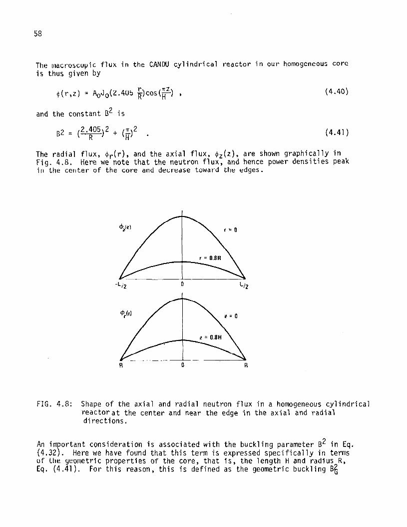
The radial flux, ~r{r), and the axial flux, ~z(z), are shown graphically inFig. 4.8. Here we note that the neutron flux, and hence power densities peakin the center of the core and decrease toward the edges.
R R
FIG. 4.8: Shape of the axial and radial neutron flux in a homogeneous cylindricalreactorat the center and near the edge in the axial and radialdirections.
An important consideration is associated with the buckling parameter B2 in Eq.(4.32). Here we have found that this term is expressed specifically in termsof the geometric properties of the core, that is, the length H and radius R,Eq. (4.41). For this reason, this is defined as the geometric buckling B~
59
(4.42)
to distinguish it from the material buckling B~, Eq. (4.28). Since both fluxequations, Eq. (~.26) and Eq. (~.29) describe the neutron flux for a steadystate critical reactor, the two buck1ings must of necessity be the same. Hencethe geometric properties are related to the material properties and we equateB~ with B~
k - 1 (2 .~05)2 + (~)200
L2 =
or, in a more common form
k00
1+ L2B2 =
1 G
(4.43)
(4.44)
Thus, to attain a steady-state critical reactor the materials composition mustbe s02chosen and the reactor dimensions so specified that the parameters k~> L2and BG satisfy Eq. (4.44).
4.5 HETEROGENEOUS CORE
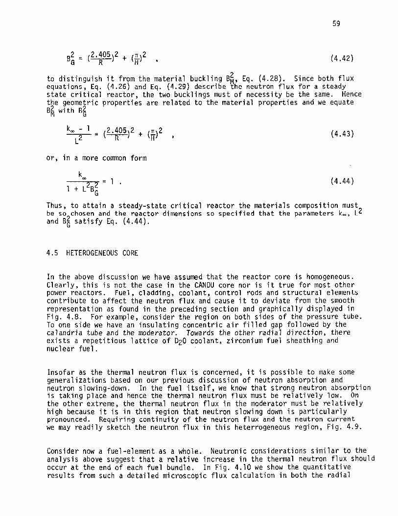
In the above discussion we have assumed that the reactor core is homogeneous.Clearly, this is not the case in the CANDU core nor is it true for most otherpower reactors. Fuel, cladd1ng, coolant, control rods and structural elelllenLscontribute to affect the neutron flux and cause it to deviate from the smoothrepresentation as found in the preceding section and graphically displayed inFig. 4.8. For example, consider the region on both sides of the pressure tube.To one side we have an insulating concentric air filled gap followed by thecalandria tube and the moderator. Towards the other radial direction, thereexists a repetitious lattice of D20 coolant, zirconium fuel sheathing andnuclear fuel.
Insofar as the thermal neutron flux is concerned, it is possible to make somegeneralizations based on our previous discussion of neutron absorption andneutron slowing-down. In the fuel itself, we know that strong neutron absorptionis taking place and hence the thermal neutron flux must be relatively low. Onthe other extreme, the thermal neutron flux in the moderator must be relativelyhigh because it is in this region that neutron slowing down is particularlypronounced. Requiring continuity of the neutron flux and the neutron currentwe may readily sketch the neutron flux in this heterrogeneous region, Fig. 4.9.
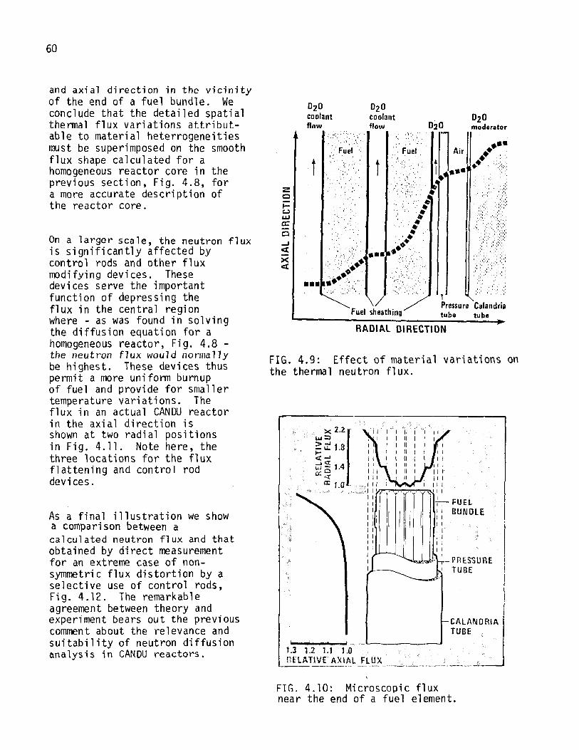
Consider now a fuel-element as a whole. Neutronic considerations similar to theanalysis above suggest that a relative increase in the thermal neutron flux shouldoccur at the end of each fuel bundle. In Fig. 4.10 we show the quantitativeresults from such a detailed microscopic flux calculation in both the radial
60
FunBUN OLE
lPressure Calandriatube tube
t
02 0coolantflow
.<' ,
,', Fuel
RADIAL DIRECTION
Fuel sheathing
t
°2°coolantflow
CALANORIATUBE
:2:C
lt.)wa:o-I«Xct
x 2.21'w::l
~ it 1,8<t .......J et 4wot.c.::~
a: La .
I ! ! .... .,-L--. ._..._--'
1.3 1.2 1.1 1.0nUATIV£ AXIAL flUX----_... -.-. -"=-:...:__.----------._._"--~--,--
PRESSUREI TUBE
FIG. 4.9: Effect of material variations onthe thermal neutron flux.
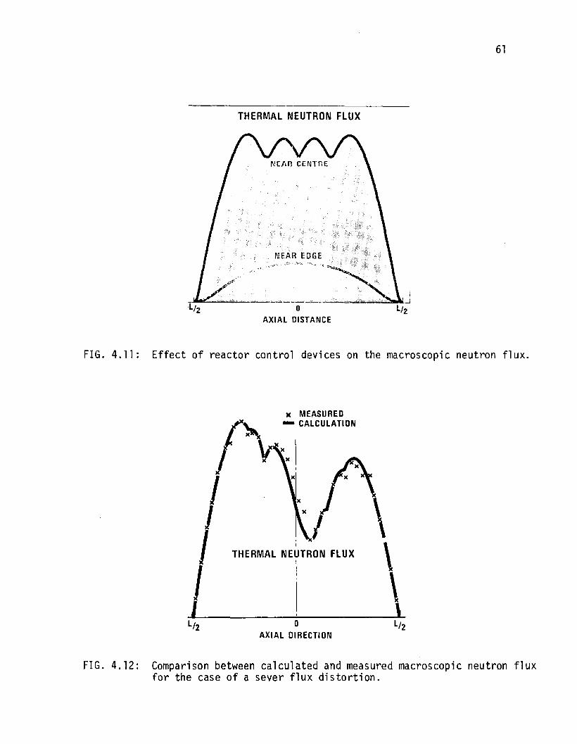
On a larger scale, the neutron fluxis significantly affected bycontrol rods and other fluxmodifying devices. Thesedevices serve the importantfunction of depressing theflux in the central regionwhere - as was found in solvingthe diffusion equation for ahomogeneous reactor, Fig. 4.8 -the neutron flux would nonnal1ybe highest. These devices thuspermit a more uniform burnupof fuel and provide for smallertemperature variations. Theflux in an actual CANDU reactorin the axial direction isshown at two radial positionsin Fig. 4.11. Note here, thethree locations for the fluxflattening and control roddevi ces.
As a final illustration we showa comparison between acalculated neutron flux and thatobtained by direct measurementfor an extreme case of nonsymmetric flux distortion by aselective use of control rods,Fig. 4.12. The remarkableagreement between theory andexperiment bears out the previouscomment about the relevance andsuitability of neutron diffusionanalysis in CANDU reactors.
and axial direction in the vicinityof the end of a fuel bundle. Weconclude that the detailed spatialthermal flux variations attributable to material heterrogeneitiesmust be superimposed on the smoothflux shape calculated for ahomogeneous reactor core in theprevious section, Fig. 4.8, fora more accurate description ofthe reactor core.
FIG. 4.l0~ Microscopic fluxnear the end of a fuel element.
THERMAL NEUTRON flUX
I
61
THERMAL NEUTRON flUX
FIG. 4.11: Effect of reactor control devices on the macroscopic neutron flux.
\\\
____~-----:'lo L/2
AXIAL DIRECTION
FIG. 4.12: Comparison between calculated and measured macroscopic neutron fluxfor the case of a sever flux distortion.

62