Embed Size (px)
Citation preview

Chapter 4Optimal Pulse Shaping for Ultrafast LaserInteraction with Quantum Systems
Hyosub Kim, Hangyeol Lee, Jongseok Lim and Jaewook Ahn
Abstract Coherent control method steers a quantum system to a desirable finalquantum state among a number of final states otherwise possible in a given light-matter interaction, by using a specially shaped light form programmed in its spectraland/or temporal domain. In this chapter, we briefly review a number of light-formshaping methods previously considered for coherent control of ultra-fast laser interac-tion with atoms, and provide their application examples along with their experimentaldemonstrations.
4.1 Introduction
Latest development in laser optics manifests a new capability of light, other thanthe traditional use of light as a viewing tool, which is the use of light as a controltool. In particular, along with the advent of ultra-fast optical techniques, it becomespossible that the versatile light forms are newly engineered by programming theamplitude and shape functions of the broad frequency range of an ultra-fast opticalpulse. As a result, the programmed spectral and/or temporal shape of a laser pulsecan be used as a quantum-mechanical means to control the dynamics of a quantumsystem. This field of optical research is refereed to as coherent control, or quantumcontrol, or more specifically to emphasize the usage of ultra-fast laser, “ultra-fastquantum control.”
Examples of the coherent control concepts demonstrated in terms of shaped light-matter interactions can be found in numerous experiments. To list a few, historicallyWilson and coworkers [1] experimentally realized closed-loop feedback control ofoptimal pulse shape for efficient population transfer in molecular system. Gerber
H. Kim · H. Lee · J. Lim · J. Ahn (B)
Department of Physics, Korea Advanced Institute of Science and Technology (KAIST),291 Daehak-ro, Yuseong-gu, Daejeon 305-701, Koreae-mail: [email protected]
K. Yamanouchi et al. (eds.), Progress in Ultrafast Intense Laser Science XI, 73Springer Series in Chemical Physics 109, DOI: 10.1007/978-3-319-06731-5_4,© Springer International Publishing Switzerland 2015
74 H. Kim et al.
and coworkers [2] also demonstrated the coherent control in the photo-dissociationprocess of molecules, by using shaped ultra-fast optical pulses which were adaptivelyprogrammed in a closed control loop consisted of a laser programming apparatusand a photo-fragment mass spectroscope. Although the adaptive control methods arepowerful in many real applications, we leave this class of coherent control meth-ods aside and focus on the open-loop coherent control method, where the laserpulse shape is first designed by solving the Schrödinger equation for the given light-matter interaction. In that context, Silberberg and coworkers [3] initiated the pulseshape design research in terms of coherent control in their demonstration of atomicnonlinear absorption process. Other examples can be found, for example, in opticalsecond-harmonic generation [4], optical third-harmonic generation [5], multi-photonabsorption [6, 7], and coherent anti-Stokes Raman scattering [8]. More advancedapplications can be found in in-vivo fluorescence microscopy [9], coherent controlquantum bits in Rydberg atoms [10], and semiconductor [11] to list a few.
The research of coherent control of quantum dynamics has become possible inmany ways thanks to the development of laser pulse shaping apparatus in the lasttwo decades [12]. Among many apparatus, spatial light modulators (SLM), in par-ticular, allow a relative easy way to engineer the interference among the transitionpathways of a multi-photon absorption process, because of their Fourier domainspectral shaping capability [3, 6]. Also, acousto-optic programmable dispersive fil-ters (AOPDF) provide more sophisticated ways of pulse-shaping in the context of thischapter, showing its capability, for example, in the strong-field multi-photon absorp-tion control of alkali atoms [7, 13]. A combination of those pulse-shaping devicescan transform a well-defined gaussian-shape pulse to an arbitrary pulse shape ofprogrammed spectral phase, amplitude, and also polarization [14–18].
4.2 Types of Pulse Shaping
Before we begin to describe the coherent control experiments, we categorize theways of pulse shaping methods. To do that, we first need to define an ultra-fast laserpulse.
The ultra-fast laser pulse can be represented either in time domain as E(t), or infrequency domain E(ω), where their mutual relation is given by the complex Fouriertransform (F ). The most interesting case in this context of ultra-fast optical pulseshaping is a moderately short pulse, which means the center carrier frequency ω0,and the bandwidth of the pulse Δω are related as Δω � ω0 [19]. Then, without aloss of generality, the electric field is factored into the envelope and carrier functionsgiven by
E(t) = 1
2ε(t)eiφ(t)eiω0t + c.c., (4.1)
4 Optimal Pulse Shaping for Ultrafast Laser Interaction 75
and its frequency domain representation is given by
E(ω) = F {E(t)} = |E(ω)|eiΦ(ω), (4.2)
where the tilde denotes a complex value and, since E(t) is real function, a relationE(ω) = E∗(−ω) holds.
It is noted that we neglect the spatial profile of the laser pulse, which often playsan important role in nonlinear optical process in terms of spatial average effect [20],but we assume the given light-matter interaction is performed in an uniform spatialintensity region only.
As seen in (4.1), the electric field of the pulse is described by its center carrierfrequency ω0 and its transient envelope function ε(t). The Fourier transform of thistemporal profile yields the same analogy in the frequency domain, which is centeredat ω0. Here, we call |E(ω)| as a spectral amplitude and Φ(ω − ω0) as a spectralphase. It is noted that the spectral phase is a function of frequency, and, in particular,if the spectral phase is a constant over the whole spectrum range, the laser pulse isreferred to as a Fourier transform-limited pulse.
The spectral phase can be expanded into a Taylor series as
Φ(ω) = Φ(ω0) + Φ ′(ω − ω0) + 1
2Φ ′′(ω − ω0)
2 + 1
6Φ ′′′(ω − ω0)
3 + · · · , (4.3)
where the constant phase Φ(ω0) is the carrier-envelop phase, Φ ′ is the movement ofpulse envelope along the positive time direction, (which is in fact equivalent to thefrequency shift of ω0), Φ ′′ is the linear spectral chirp, and Φ ′′′ is the quadratic spectralchirp, etc. As a pulse shape contains both the envelop shape and phase informationat the same time, pulse shaping control is equivalent to both the amplitude andphase shape manipulation of the laser pulse. Also, as the actually time and frequencydomains are related with respect to the Fourier transform relation, only one of thedomain control, either time or frequency, is sufficient for the generation of a desiredshape programming of a laser pulse.
The pulse shaping device generally operates in spectral domain, to be discussedin Sect. 4.3, so we can categorize the types of pulse shaping in spectral domain asfollowing:
1. Amplitude shaping (lose photons: irreversible shaping)
a. Spectral amplitude blockingb. Wavelength scanning (regular spectroscopy)
2. Phase shaping (temporal rearrangement of spectral components)
a. Spectral chirpingb. Multiple pulses (e.g., 2D-Fourier transform spectroscopy)c. Spectral phase gatingd. Spectral phase step
76 H. Kim et al.
The amplitude shaping methods in spectral domain inevitably lose photons, and,therefore, this type of pulse shaping methods is intrinsically an irreversible process.However, to be described in Sect. 4.4, certain light-matter interactions are betterperformed with a smaller set of spectral components of light. For example, in thetwo-photon absorption case in a three-level atom with an intermediate energy level,a certain part of laser spectrum participates to the net absorption as a destructivequantum interference. Therefore, removing those spectral components, to make theremaining absorption pathways all constructively interfere with each other, couldenhance the net absorption probability. This method is known as spectral blocking[6, 21, 22]. Another method is a wavelength scanning which could be implementedby allowing only a narrow spectral region of an ultra-fast pulse and blocking theothers.
The spectral phase shaping is a way of temporal rearrangement of spectral com-ponents, and this method allows a variety of ways of spectral manipulation of a laserpulse. For example, spectral phase gating method provides a narrow spectral windowregion (phase-gated window) to be of different phase from the others, and scans thephase-gated spectral window from one end to the other end of the laser spectrum.Also, one can make a spectral phase step in a certain spectral location of the spectrumand scan the phase-step location, or one can implement a modulated spectral phasefunction Φ(ω) = A cos(Bω + C) and by controlling the modulation amplitude A,the modulation frequency B, or the modulation phase C , respectively, the popu-lation transfer among the energy levels of the given light-matter interaction can beenhanced or suppressed. Another example is a use of multiple laser pulses, which canbe programmed in the phase-shaping in spectral domain. For example, a set of threelaser pulses with a fixed carrier-envelope phase and variable time delays implementstwo-dimensional Fourier transform spectroscopy. One could change the frequencyde-tuning, the spectral linear chirp, or the spectral quadratic chirp by changing Φ ′,Φ ′′, or Φ ′′′, respectively, which subject will be discussed in more detail in Sect. 4.5.Lastly, if the transition phase information is completely known a priori, then a spec-tral phase function which maximizes the given transition can be programmed to bediscussed in Sect. 4.6.
4.3 Pulse Shaping Devices
Although the pulse shaping methods are performed in both the Fourier and timedomains, the tailored pulse can be described in either domain completely. Thus weconcentrate on the frequency domain1 shaping here. When we deal with a pulse atfrequency domain, angular dispersive optical elements, such as a prism or a diffrac-tion grating, can be used [23, 24]. As such optical elements disperse each chromaticcomponent at a different spatial position in the real plane, managing each chromatic
1 We notice that Fourier domain and frequency domain have the same physical meaning in thischapter.

4 Optimal Pulse Shaping for Ultrafast Laser Interaction 77
Fig. 4.1 An optical pulse shaper combined with a pair of diffraction gratings and a liquid crystalSLM. Phase, and amplitude, or both phase and amplitude are controllable according to respectivetypes of configurations of an SLM, inserted wave plates, and polarizers. The image is from [27]with permission by the publisher
ray at different position would possibly manipulate the shape of the pulse in thefrequency domain. In the contrary to frequency domain, time domain control canbe done by acousto-optic effect [16]. Programmable acoustic waves generated bypiezo-electric transducer in an acousto-optic crystal convolute with incident pulsesand generate desired pulse shape.
Spectral amplitude and phase functions can be controlled either by a fixedmask [23], or by a variable masks: For example, SLM [25, 26], AOPDF [17], andetc [27]. We briefly describe the working principles of SLM and AOPDF, before westart to discuss the experiments performed with these devices.
4.3.1 Spatial Light Modulator
SLM is an array of optical phase or amplitude (or both) modulators made out of liquidcrystals. The liquid crystal in a nematic phase is a uniaxial birefringent material andits molecular orientation is easily controllable by means of an applied electric field.A usual setup, shown in the Fig. 4.1, is used as an optical pulse shaper, where anSLM pulse shaper is located in the Fourier plane of a 2f-to-2f configuration of lensand diffraction grating setup, also known as Martinez zero-dispersion stretcher setup[27, 28]. The phase of light transmitted through each liquid crystal pixel is given asa function of both the incident polarization and the electric field applied to the pixel.For example, in the case of a phase-only modulation SLM, the extra-ordinary axis ofthe liquid crystal is oriented originally parallel to incident polarization and, when theelectric field is applied to the propagating direction of light, optical path length can bemanaged without birefringence. With appropriate combinations of half-wave platesand polarizers, amplitude-modulation and both amplitude-and-phase modulation arealso possible.

78 H. Kim et al.
Fig. 4.2 Schematic of the AOPDF. Traveling acoustic wave diffracts phase-matched optical mode.The image is from [17] with permission by the publisher
4.3.2 Acousto-Optic Programmable Dispersive Filter
The working principle of AOPDF is based on collinear acousto-optic interaction,where a programmed acoustic wave diffracts different spectral components, of anultra-fast laser pulse, that are respectively phase-matched with different acousticmodes in the AOPDF [16]. Thus, the output laser spectral amplitude Eout is pro-grammed as Eout ∝ Ein S(αω), where Ein is the input laser spectral amplitude andS(αω) is the acoustic mode amplitude and α is the ratio between the speed of soundand the speed of light in the crystal (Fig. 4.2).
4.4 Spectral Amplitude Blocking
4.4.1 A Ladder-Type System
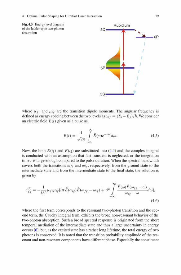
As the first example of coherent control experiments, we consider the spectral block-ing among spectral amplitude shaping methods. The quantum system under consid-eration is the three-level system in a ladder configuration of atomic rubidium (Rb).The three energy levels are the 5S (the ground state), 5P1/2 (the intermediate state),and 5D states (the final state), as shown in the Fig. 4.3. The coherent light source isfrom a mode-locked Ti:sapphire laser, of which the wavelength center is at 778 nmand the broad wavelength width of 18 nm in FWHM (the full width at half maximum)covers both the upper and lower intermediate states energy separation.
The transition probability amplitude to the final state is given by the second ordertime dependent perturbation theory [6] as,
c(2)(t) = − 1
�2
∑
i
μ f iμig
t∫
−∞
t1∫
−∞E(t1)E(t2)e
iω f i t1 eiωig t2 dt2dt1, (4.4)
4 Optimal Pulse Shaping for Ultrafast Laser Interaction 79
Fig. 4.3 Energy level diagramof the ladder-type two-photonabsorption
5D
5P
5S
Rubidium
6P
where μ f i and μig are the transition dipole moments. The angular frequency isdefined as energy spacing between the two levels as ωi j ≡ (Ei − E j )/�. We consideran electric field E(t) given as a pulse as,
E(t) = 1√2π
∞∫
−∞E(ω)e−iωt dω. (4.5)
Now, the both E(t1) and E(t2) are substituted into (4.4) and the complex integralis conducted with an assumption that fast transient is neglected, or the integrationtime t is large enough compared to the pulse duration. When the spectral bandwidthcovers both the transitions ω f i and ωig , respectively, from the ground state to theintermediate state and from the intermediate state to the final state, the solution isgiven by
c(2)f g = − 1
i�2 μ f iμig[iπ E(ωig)E(ω f g − ωig) + P
∞∫
−∞
E(ω)E(ω f g − ω)
ωig − ωdω],
(4.6)
where the first term corresponds to the resonant two-photon transition and the sec-ond term, the Cauchy integral term, exhibits the broad non-resonant behavior of thetwo-photon absorption. Such a broad spectral response is originated from the shorttemporal mediation of the intermediate state and thus a large uncertainty in energyoccurs [6], but, as the excited state has a rather long lifetime, the total energy of twophotons is conserved. It is noted that the transition probability amplitude of the res-onant and non-resonant components have different phase. Especially the constituent
80 H. Kim et al.
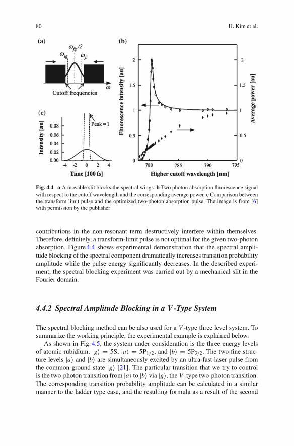
Fig. 4.4 a A movable slit blocks the spectral wings. b Two photon absorption fluorescence signalwith respect to the cutoff wavelength and the corresponding average power. c Comparison betweenthe transform limit pulse and the optimized two-photon absorption pulse. The image is from [6]with permission by the publisher
contributions in the non-resonant term destructively interfere within themselves.Therefore, definitely, a transform-limit pulse is not optimal for the given two-photonabsorption. Figure 4.4 shows experimental demonstration that the spectral ampli-tude blocking of the spectral component dramatically increases transition probabilityamplitude while the pulse energy significantly decreases. In the described experi-ment, the spectral blocking experiment was carried out by a mechanical slit in theFourier domain.
4.4.2 Spectral Amplitude Blocking in a V-Type System
The spectral blocking method can be also used for a V -type three level system. Tosummarize the working principle, the experimental example is explained below.
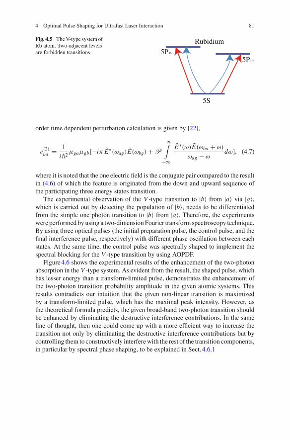
As shown in Fig. 4.5, the system under consideration is the three energy levelsof atomic rubidium, |g〉 = 5S, |a〉 = 5P1/2, and |b〉 = 5P3/2. The two fine struc-ture levels |a〉 and |b〉 are simultaneously excited by an ultra-fast laser pulse fromthe common ground state |g〉 [21]. The particular transition that we try to controlis the two-photon transition from |a〉 to |b〉 via |g〉, the V -type two-photon transition.The corresponding transition probability amplitude can be calculated in a similarmanner to the ladder type case, and the resulting formula as a result of the second
4 Optimal Pulse Shaping for Ultrafast Laser Interaction 81
Fig. 4.5 The V-type system ofRb atom. Two-adjacent levelsare forbidden transitions
5S
5P1/2
5P3/2
Rubidium
order time dependent perturbation calculation is given by [22],
c(2)ba = 1
i�2 μgaμgb[−iπ E∗(ωag)E(ωbg) + P
∞∫
−∞
E∗(ω)E(ωba + ω)
ωag − ωdω], (4.7)
where it is noted that the one electric field is the conjugate pair compared to the resultin (4.6) of which the feature is originated from the down and upward sequence ofthe participating three energy states transition.
The experimental observation of the V -type transition to |b〉 from |a〉 via |g〉,which is carried out by detecting the population of |b〉, needs to be differentiatedfrom the simple one photon transition to |b〉 from |g〉. Therefore, the experimentswere performed by using a two-dimension Fourier transform spectroscopy technique.By using three optical pulses (the initial preparation pulse, the control pulse, and thefinal interference pulse, respectively) with different phase oscillation between eachstates. At the same time, the control pulse was spectrally shaped to implement thespectral blocking for the V -type transition by using AOPDF.
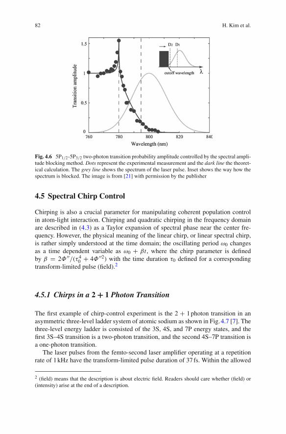
Figure 4.6 shows the experimental results of the enhancement of the two-photonabsorption in the V -type system. As evident from the result, the shaped pulse, whichhas lesser energy than a transform-limited pulse, demonstrates the enhancement ofthe two-photon transition probability amplitude in the given atomic systems. Thisresults contradicts our intuition that the given non-linear transition is maximizedby a transform-limited pulse, which has the maximal peak intensity. However, asthe theoretical formula predicts, the given broad-band two-photon transition shouldbe enhanced by eliminating the destructive interference contributions. In the sameline of thought, then one could come up with a more efficient way to increase thetransition not only by eliminating the destructive interference contributions but bycontrolling them to constructively interfere with the rest of the transition components,in particular by spectral phase shaping, to be explained in Sect. 4.6.1
82 H. Kim et al.
Fig. 4.6 5P1/2-5P3/2 two-photon transition probability amplitude controlled by the spectral ampli-tude blocking method. Dots represent the experimental measurement and the dark line the theoret-ical calculation. The grey line shows the spectrum of the laser pulse. Inset shows the way how thespectrum is blocked. The image is from [21] with permission by the publisher
4.5 Spectral Chirp Control
Chirping is also a crucial parameter for manipulating coherent population controlin atom-light interaction. Chirping and quadratic chirping in the frequency domainare described in (4.3) as a Taylor expansion of spectral phase near the center fre-quency. However, the physical meaning of the linear chirp, or linear spectral chirp,is rather simply understood at the time domain; the oscillating period ω0 changesas a time dependent variable as ω0 + βt , where the chirp parameter is definedby β = 2Φ ′′/(τ 4
0 + 4Φ ′′2) with the time duration τ0 defined for a correspondingtransform-limited pulse (field).2
4.5.1 Chirps in a 2 + 1 Photon Transition
The first example of chirp-control experiment is the 2 + 1 photon transition in anasymmetric three-level ladder system of atomic sodium as shown in Fig. 4.7 [7]. Thethree-level energy ladder is consisted of the 3S, 4S, and 7P energy states, and thefirst 3S–4S transition is a two-photon transition, and the second 4S–7P transition isa one-photon transition.
The laser pulses from the femto-second laser amplifier operating at a repetitionrate of 1 kHz have the transform-limited pulse duration of 37 fs. Within the allowed
2 (field) means that the description is about electric field. Readers should care whether (field) or(intensity) arise at the end of a description.

4 Optimal Pulse Shaping for Ultrafast Laser Interaction 83
Fig. 4.7 The asymmetric three-level energy ladder in atomic sodium and the 2+photon transitionpathway from 3S to 7P via 4S. The direct four-photon ionized atom signal is 1,000 times smallerthan the 4S-7P sequential 2 + 1 photon transition, thus the system is valid as a closed three-levelsystem. The image is from [7] with permission by the publisher
laser bandwidth there is no intermediate state during the two-photon 3S–4S transition,and, therefore, the 3S–4S transition is non-resonant.
When the chirp rate was controlled by AOPDF, as in Fig. 4.8, the 7P state popu-lation was measured as a function of the chirp rate of the excitation laser pulse. Theexperimental results show highly asymmetric behavior of the three photon excitedstate population given as a function of the chirp rate. The physical origin of theasymmetry can be explained by the different excitation pathways: One is the 4S-state mediated sequential 2 + 1 photon excitation path and the other is a direct threephoton excitation path. In the case of the former path, the first two-photon excita-tion has a higher frequency (777 nm) and the last one-photon excitation has a lowerfrequency (781 nm), thus the transient character of the excitation process prefers anegative chirp rate and, therefore, is the main reason of the observed asymmetry.The latter path has no reason to have such an asymmetry, rather it shows symmetricbehavior with zero population at zero chirp rate, which can be easily observed inthe green dot-dashed line in Fig. 4.8. The reason can be understood based on theeffect of the dynamic Stark shift which makes the intensity proportional resonancelevel de-tuning in the presence of the laser pulse [29]. In this scenario, the zero chirppoint has the highest intensity, because the largest dynamic Stark shift occurs, andthe direct three photon transition path becomes far off de-tuned from the resonanceenergy condition, which explains the symmetric nature of the intensity shape witha dip at the zero chirp region. Interference between direct path and sequential pathcauses also considerable effect in multi-photon transition system [30]. However, inthe 2 + 1 photon system, calculation based on perturbation theory shows that chirprates in the experiment are not enough to observe interference fringes.

84 H. Kim et al.
Fig. 4.8 Sodium 2 + 1 photon transition measured as a function of the chirp rate. Experimentalresults plotted by dots are compared with the theoretical calculation (the lines). The 2 + 1, photonsequential transition pathway is in the blue dashed line and the three photon direct transition is inthe green dot-dashed line which are asymmetric and symmetric respectively. The black solid linerepresents the total absorption rate. The image is from [7] with permission by the publisher
4.5.2 Chirps in Two-Photon Transitions
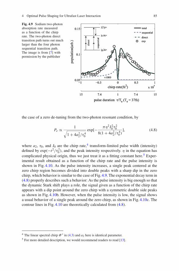
The excitation suppression due to the dynamic Stark effect can be better identified byobserving the 3S−4S two-photon transition. As shown in Fig. 4.9, 3S–4S two-photondirect transition path is dominant compared to the four-photon sequential transitionpath,3 and, therefore, an observation of the 4 s state population as a function of thechirp rate provides a clear evidence for the dynamic Stark effect induced transitionreduction.
Experimental result in atomic cesium also finds a similar effect. As a two-photontransition without any resonant intermediate transition, which often referred to as anon-resonant two-photon transition, the 6S–8S transition in cesium is strongly influ-enced by the dynamic Stark shift in the presence of an intense laser field. In theexperiment carried out with a laser intensity around 1012 W/cm2, or in the strongfield regime, the chirp rate dependence on the two-photon transition has been inves-tigated [13].
Theoretical consideration for the 3S −4S two-photon transition probability givesan analytical formula given as a function of the chirp rate and the pulse intensity, for
3 Four-photon sequential path is 3S−4S−7P 2+1 photon process in addition to 7P−4S one-photonde-excitation. In this experiment, several order of magnitude is smaller than two-photon direct path.
4 Optimal Pulse Shaping for Ultrafast Laser Interaction 85
Fig. 4.9 Sodium two-photonabsorption rate measuredas a function of the chirprate. The two-photon directtransition path turns out muchlarger than the four photonsequential transition path.The image is from [7] withpermission by the publisher
the case of a zero de-tuning from the two-photon resonant condition, by
Pe ∝ 1√1 + 4a2
2/τ 40
exp[− πη2 I 20 τ 2
0
8(1 + 4a22/τ 4
0 )], (4.8)
where a2, τ0, and I0 are the chirp rate,4 transform-limited pulse width (intensity)defined by exp(−t2/τ 2
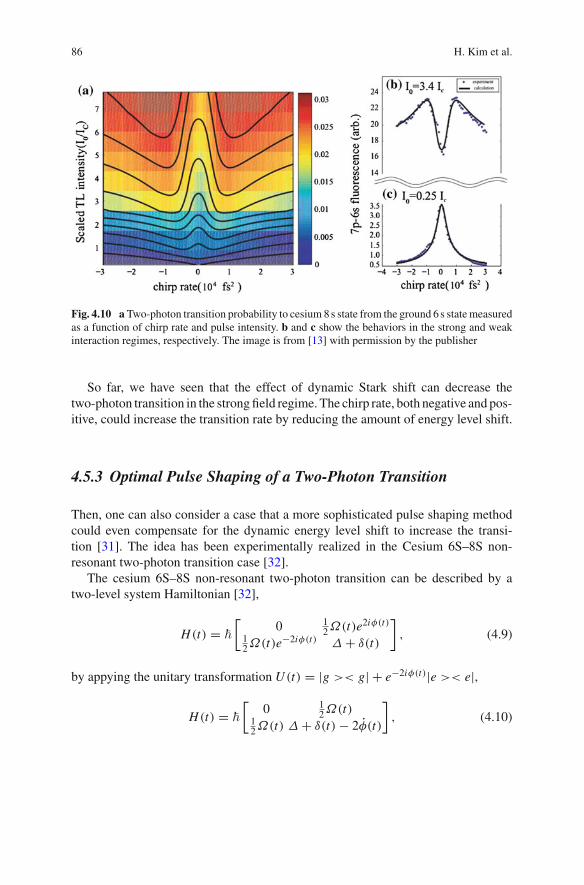
0 ), and the peak intensity respectively. η in the equation hascomplicated physical origin, thus we just treat it as a fitting constant here.5 Exper-imental result obtained as a function of the chirp rate and the pulse intensity isshown in Fig. 4.10. As the pulse intensity increases, a single peak centered at thezero chirp region becomes divided into double peaks with a sharp dip in the zerochirp, which behavior is similar to the case of Fig. 4.9. The exponential decay term in(4.8) properly describes such a behavior: As the pulse intensity is big enough so thatthe dynamic Stark shift plays a role, the signal given as a function of the chirp rateappears with a dip point around the zero chirp with a symmetric double side peaksas shown in Fig. 4.10b. However, when the pulse intensity is low, the signal showsa usual behavior of a single peak around the zero chirp, as shown in Fig. 4.10c. Thecontour lines in Fig. 4.10 are theoretically calculated from (4.8).
4 The linear spectral chirp Φ ′′ in (4.3) and a2 here is identical parameter.5 For more detailed description, we would recommend readers to read [13].
86 H. Kim et al.
Fig. 4.10 a Two-photon transition probability to cesium 8 s state from the ground 6 s state measuredas a function of chirp rate and pulse intensity. b and c show the behaviors in the strong and weakinteraction regimes, respectively. The image is from [13] with permission by the publisher
So far, we have seen that the effect of dynamic Stark shift can decrease thetwo-photon transition in the strong field regime. The chirp rate, both negative and pos-itive, could increase the transition rate by reducing the amount of energy level shift.
4.5.3 Optimal Pulse Shaping of a Two-Photon Transition
Then, one can also consider a case that a more sophisticated pulse shaping methodcould even compensate for the dynamic energy level shift to increase the transi-tion [31]. The idea has been experimentally realized in the Cesium 6S–8S non-resonant two-photon transition case [32].
The cesium 6S–8S non-resonant two-photon transition can be described by atwo-level system Hamiltonian [32],
H(t) = �
[0 1
2Ω(t)e2iφ(t)
12Ω(t)e−2iφ(t) Δ + δ(t)
], (4.9)
by appying the unitary transformation U (t) = |g >< g| + e−2iφ(t)|e >< e|,
H(t) = �
[0 1
2Ω(t)12Ω(t) Δ + δ(t) − 2φ(t)
], (4.10)
4 Optimal Pulse Shaping for Ultrafast Laser Interaction 87
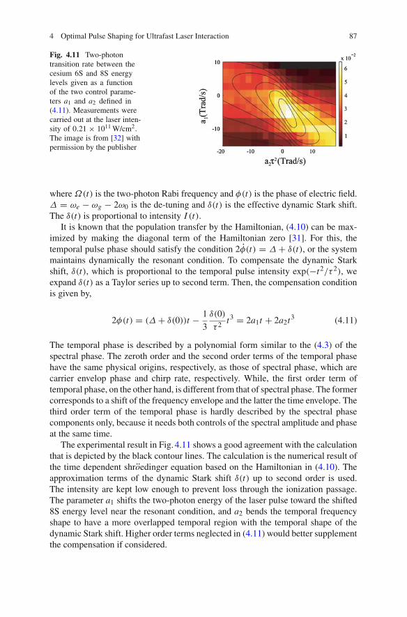
Fig. 4.11 Two-photontransition rate between thecesium 6S and 8S energylevels given as a functionof the two control parame-ters a1 and a2 defined in(4.11). Measurements werecarried out at the laser inten-sity of 0.21 × 10¹¹ W/cm2.The image is from [32] withpermission by the publisher
where Ω(t) is the two-photon Rabi frequency and φ(t) is the phase of electric field.Δ = ωe − ωg − 2ω0 is the de-tuning and δ(t) is the effective dynamic Stark shift.The δ(t) is proportional to intensity I (t).
It is known that the population transfer by the Hamiltonian, (4.10) can be max-imized by making the diagonal term of the Hamiltonian zero [31]. For this, thetemporal pulse phase should satisfy the condition 2φ(t) = Δ + δ(t), or the systemmaintains dynamically the resonant condition. To compensate the dynamic Starkshift, δ(t), which is proportional to the temporal pulse intensity exp(−t2/τ 2), weexpand δ(t) as a Taylor series up to second term. Then, the compensation conditionis given by,
2φ(t) = (Δ + δ(0))t − 1
3
δ(0)
τ 2 t3 = 2a1t + 2a2t3 (4.11)
The temporal phase is described by a polynomial form similar to the (4.3) of thespectral phase. The zeroth order and the second order terms of the temporal phasehave the same physical origins, respectively, as those of spectral phase, which arecarrier envelop phase and chirp rate, respectively. While, the first order term oftemporal phase, on the other hand, is different from that of spectral phase. The formercorresponds to a shift of the frequency envelope and the latter the time envelope. Thethird order term of the temporal phase is hardly described by the spectral phasecomponents only, because it needs both controls of the spectral amplitude and phaseat the same time.
The experimental result in Fig. 4.11 shows a good agreement with the calculationthat is depicted by the black contour lines. The calculation is the numerical result ofthe time dependent shroedinger equation based on the Hamiltonian in (4.10). Theapproximation terms of the dynamic Stark shift δ(t) up to second order is used.The intensity are kept low enough to prevent loss through the ionization passage.The parameter a1 shifts the two-photon energy of the laser pulse toward the shifted8S energy level near the resonant condition, and a2 bends the temporal frequencyshape to have a more overlapped temporal region with the temporal shape of thedynamic Stark shift. Higher order terms neglected in (4.11) would better supplementthe compensation if considered.
88 H. Kim et al.
4.5.4 Chirps in a V-Type System
It is worth to mention the effects of chirps on the V -type two-photon transition [22].The transition probability of (4.7) for the V -type two-photon transition can be sim-plified when the pulse envelope is assumed to be of a gaussian shape, and the spectralphase has a chirp (a2) and a quadratic chirp (a3) only. After a straightforward algebra,the given 2-photon transition can be written as
c(2)ba = i
μba
�2 [iπ E (ω) − P
∞∫
∞
E (ω)
ω − ωdω], (4.12)
where μba = μgaμbg exp [−ω2ba/2Δω2 + ia3ω
3ba/24], ω = (ωag + ωbg)/2, and
E (ω) = |E(ω)|2 exp (iωbadφ/dω) is the effective electric field. We just write downthe one-photon de-excitation probability amplitude calculated by first order pertur-bation [22],
c(1)ge = iμeg E0
�
t∫
−∞exp (− t ′2
τ 2c
) × exp {−i[(ωeg − ω0)t′ − αt ′2]}dt ′
F.T=μeg
�[iπ E∗(ωeg) − P
∞∫
−∞
E∗(ω)ei(ω−ωeg)t
ωeg − ωdω], (4.13)
where τc = τ0
√1 + a2
2/τ 40 , α = 2a2/(τ
40 + 4a2
2), and τ0 is the transform-limitedpulse width (field) [22]. The readers should notice that the linear chirp rate is intro-duced in the de-excitation pulse for the case of (4.13). At time t = 0, (4.12) and thesecond (4.13) are of a similar form. Thus, the V-type two-photon transition processmay be reduced to a one-photon de-excitation process. We conduct inverse Fouriertransformation of (4.12) with an appropriate substitution of the effective electric fieldE (ω) by a temporal shift t = ωbaa2 and a chirp a2 = −ωbaa3. We can find its timedomain form of (4.12) as
c(2)ba = − μba E2
0eiθ
�2
Δω√τc/τ0
t∫
−∞exp (− t ′2
τ 2c
)
× exp {−i[(ω − ω0)t′ − αt ′2]}dt ′ (4.14)
where θ = − 12 tan−1 2a2/τ
20 + (ω −ω0)t , τ0 = 2
√2/Δω, τc = τ0
√1 + a2
2/τ 40 , and
α = 2a2/(τ40 + 4a2
2).We note that the V -type two-photon transition probability amplitude in (4.7) is a
result of infinite temporal integration, but the reduced probability amplitude in (4.14)
4 Optimal Pulse Shaping for Ultrafast Laser Interaction 89
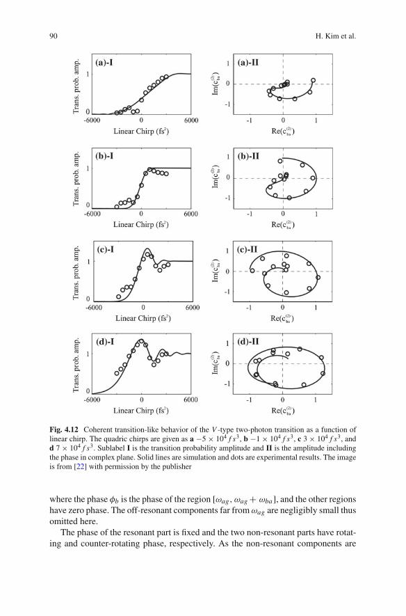
exhibits a time dependent-like form. The time dependence is in fact originated fromthe fact that the effective electric field is time-shifted proportional to the chirp rate,t = ωbaa2. Interestingly, the V -type transition shows a coherent transient (CT)-likebehavior as the chirp rate is controlled, although it should be distinguished from thereal CT effect observed in pump-probe experiments [33–35].
Experimental result shown in Fig. 4.12I indeed exhibits the fore-mentionedCT-like behavior as a function of chirp rate. It is noted that three-pulse two-dimension Fourier transform spectroscopy can recover both the amplitude and phaseof probability amplitude as shown in Fig. 4.12II.6
4.6 Spectral Phase Programming
One can also consider an arbitrary spectral phase function programming for thepurpose of an optimized multi-photon transition. In particular, if the constituenttransition pathways of the given transition are fully understood in terms of theirrespective phase information, maximally constructive quantum interference can beachieved by properly encoding the spectral phase function of the control laser pulse.
4.6.1 Spectral Phase Programming for a V-Type Transition
We consider the V -type two-photon system again, as an example. The targettransition, between the adjacent fine structure energy levels through the groundstate, is controlled by programming a spectral phase step at the spectral region[ωag, ωag + ωba]. The governing equation is given in (4.7), where the integral termof (4.7) is decomposed into two part [21] as follows:
c(2)ba i
μgaμgb
�2 [iπ E∗(ωag)E(ωbg)
− eiφb
ωag∫
ωag−ωba
E∗(ω)E(ωba + ω)
|ωag − ω| dω
+ e−iφb
ωag+ωba∫
ωag
E∗(ω)E(ωba + ω)
|ωag − ω| dω], (4.15)
6 Three ultra-fast pulses are incident on the target, with separately controllable pico-second scaletime delays τ1 and τ2 between each consecutive pulse. The excited states induced by each pulse areinterfered and the final fluorescence signal I (τ1, τ2) is recorded. Two-dimensional Fourier transformof I (τ1, τ2) acquires both amplitude and phase information. Detailed theoretical description on thisexperiment can be found from [22].
90 H. Kim et al.
Fig. 4.12 Coherent transition-like behavior of the V -type two-photon transition as a function oflinear chirp. The quadric chirps are given as a −5 × 10⁴ f s3, b −1 × 10⁴ f s3, c 3 × 10⁴ f s3, andd 7 × 10⁴ f s3. Sublabel I is the transition probability amplitude and II is the amplitude includingthe phase in complex plane. Solid lines are simulation and dots are experimental results. The imageis from [22] with permission by the publisher
where the phase φb is the phase of the region [ωag, ωag + ωba], and the other regionshave zero phase. The off-resonant components far from ωag are negligibly small thusomitted here.
The phase of the resonant part is fixed and the two non-resonant parts have rotat-ing and counter-rotating phase, respectively. As the non-resonant components are
4 Optimal Pulse Shaping for Ultrafast Laser Interaction 91
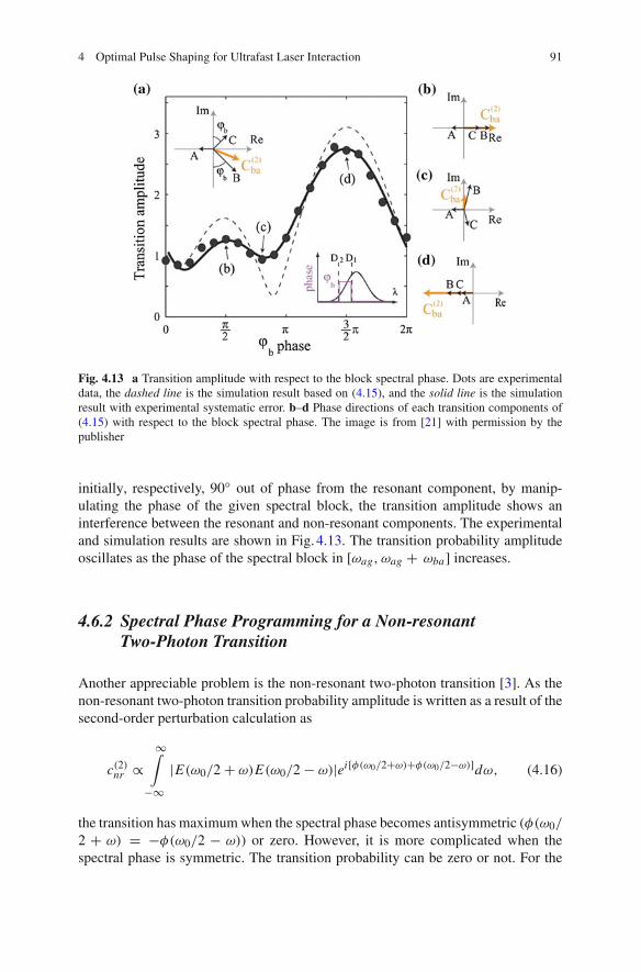
Fig. 4.13 a Transition amplitude with respect to the block spectral phase. Dots are experimentaldata, the dashed line is the simulation result based on (4.15), and the solid line is the simulationresult with experimental systematic error. b–d Phase directions of each transition components of(4.15) with respect to the block spectral phase. The image is from [21] with permission by thepublisher
initially, respectively, 90◦ out of phase from the resonant component, by manip-ulating the phase of the given spectral block, the transition amplitude shows aninterference between the resonant and non-resonant components. The experimentaland simulation results are shown in Fig. 4.13. The transition probability amplitudeoscillates as the phase of the spectral block in [ωag, ωag + ωba] increases.
4.6.2 Spectral Phase Programming for a Non-resonantTwo-Photon Transition
Another appreciable problem is the non-resonant two-photon transition [3]. As thenon-resonant two-photon transition probability amplitude is written as a result of thesecond-order perturbation calculation as
c(2)nr ∝
∞∫
−∞|E(ω0/2 + ω)E(ω0/2 − ω)|ei[φ(ω0/2+ω)+φ(ω0/2−ω)]dω, (4.16)
the transition has maximum when the spectral phase becomes antisymmetric (φ(ω0/
2 + ω) = −φ(ω0/2 − ω)) or zero. However, it is more complicated when thespectral phase is symmetric. The transition probability can be zero or not. For the

92 H. Kim et al.
Fig. 4.14 Two-photonfluorescence with respectto modulation depth, A. TheCircle and square data pointsare C = 0 and C = π respec-tively. B is fixed at 220 fs.The image is from [3] withpermission by the publisher
case of sinusoidal phase function, given by A cos(Bω + C), the experiments hasbeen performed with atomic cesium as in Fig. 4.14.
Then the two photon fluorescence signal measured as a function of the modulationdepth A, for the cases of symmetric (circle) and antisymmetric (square) phase func-tion. The antisymmetric sine phase predicts a flat, monotonic, two-photon transition,although it decays as the modulation depth grows. However, the result for a sym-metric cosine phase shows much faster decay with periodic nodes, which behavioris well understood by the theoretical consideration in (4.14).
4.7 Conclusion
We have discussed various types of laser pulse shaping methods for coherent controlof multi-level atomic systems. Spectral amplitude blocking in the ladder-type three-level two-photon transition in rubidium, and also in the V -type three-level two-photontransition in rubidium, has shown transition enhancements albeit the loss of pulseenergy. Even in a simple two-level two-photon transition, coherent controls withspectral chirps have enhanced the transition in the strong field interaction case, dueto the dynamic Stark shift, contradicting the common wisdom of nonlinear optics.Furthermore, the use of higher order chirps for the two-photon transition in a V -typethree-level system has mimicked coherent transient-like behaviors. Ultimately, it hasbeen found that optimal pulse shapes can be systematically designed by proper phasefunction programming for those transitions whose transition phase information is apriori known for all transition pathways. It is hoped that the pulse shaping methodfinds its versatile usage of ultra-short and ultra-broadband laser field not only formonitoring short time dynamics but also for surgically selective and diverse ways ofquantum system controls.
4 Optimal Pulse Shaping for Ultrafast Laser Interaction 93
References
1. C.J. Bardeen et al., Feedback quantum control of molecular electronic population transfer.Chem. Phys. Lett. 280, 151–158 (1997)
2. A. Assion et al., Control of chemical reactions by feedback-optimized phase-shaped femtosec-ond laser pulses. Science 282, 919–922 (1998)
3. D. Meshulach, Y. Silberberg, Coherent quantum control of two-photon transitions by afemtosecond laser puse. Nature 396, 239–242 (1998)
4. G. Imeshev, M.A. Arbore, M.M. Fejer, A. Galvanauskas, M. Fermann, D. Harter, Ultrashort-pulse second-harmonic generation with longitudinally nonuniform quasi-phase-matching grat-ings: pulse compression and shaping. J. Opt. Soc. Am. B. 17, 304–318 (2000)
5. S. Cialdi, M. Petrarca, C. Vicario, High-power third-harmonic flat pulse laser generation. Opt.Lett. 31, 2885–2887 (2006)
6. N. Dudovich, B. Dayan, S.M. Gallagher-Faeder, Y. Silberberg, Transform-limited pulses arenot optimal for resonant multiphoton transitions. Phys. Rev. Lett. 86, 47–50 (2001)
7. S. Lee, J. Lim, C.Y. Park, J. Ahn, Strong-field quantum control of 2 + 1 photon absorption ofatomic sodium. Opt. Express 19, 2266–2277 (2011)
8. B. Chang. Chen, S.H. Lim, Optimal laser pulse shaping for interferometric multiplex coherentanti-Stokes Raman scattering microscopy. J. Phys. Chem. B 112, 3653–3661 (2008)
9. J.P. Ogilvie et al., Use of coherent control for selective two-photon fluorescence microscopyin live organisms. Opt. Express 14, 759–766 (2006)
10. C. Rangan, P.H. Bucksbaum, Optimally shaped terahertz pulses for phase retrieval in a Rydberg-atom data register. Phys. Rev. A 64, 033417 (2001)
11. B.E. Cole, J.B. Williams, B.T. King, M.S. Sherwin, C.R. Stanley, Coherent manipulation ofsemiconductor quantum bits with terahertz radiation. Nature 410, 60–63 (2001)
12. W.S. Warren, H. Rabitz, M. Dahleh, Coherent control of quantum dynamics: the dream is alive.Science 259, 1581–1589 (1993)
13. S. Lee, J. Lim, J. Ahn, Strong-field two-photon absorption in atomic cesium: an analyticalcontrol approach. Opt. Express 17, 7648–7657 (2009)
14. A.M. Weiner, Femtosecond pulse shaping using spatial light modulators. Rev. Sci. Instrum.71, 1929 (2000)
15. A.M. Weiner, Ultrafast optical pulse shaping: a tutorial review. Opt. Comm. 284, 3669–3692(2011)
16. P. Tournois, Acousto-optic programmable dispersive filter for adaptive compensation of groupdelay time dispersion in laser systems. Opt. Comm. 140, 245–249 (1997)
17. F. Verluise et al., Amplitude and phase control of ultrashort pulses by use of an acousto-opticprogrammable dispersive filter: pulse compression and shaping. Opt. Lett. 25, 575–577 (2000)
18. T. Brixner, G. Gerber, Femtosecond polarization pulse shaping. Opt. Lett. 26, 557–559 (2001)19. J.C. Diels, W. Rudolph, Ultrashort Laser Pulse Phenomena, (Academic press, 1996), pp. 1–420. J. Lim, K. Lee, J. Ahn, Ultrafast Rabi flopping in a three-level energy ladder. Opt. Lett. 37,
3378–3380 (2012)21. J. Lim, H. Lee, S. Lee, J. Ahn, Quantum control in two-dimensional Fourier-transform spec-
troscopy. Phys. Rev. A. 84, 013425 (2011)22. J. Lim, H. Lee, J. Kim, S. Lee, J. Ahn, Coherent transients mimicked by two-photon coherent
control of a three-level system. Phys. Rev. A. 83, 053429 (2011)23. A.M. Weiner, J.P. Heritage, E.M. Kirschner, High-resolution femtosecond pulse shaping. J.
Opt. Soc. Am. B. 5, 1563 (1988)24. L. Xu et al., Programmable chirp compensation for 6-fs pulse generation with a prism-pair-
formed pulse shaper. IEEE J. Quantum Electron. 36, 893 (2000)25. M.M. Wefers, K.A. Nelson, Programmable phase and amplitude femtosecond pulse shaping.
Opt. Lett. 18, 2032 (1993)26. J.W. Wilson, P. Schlup, R.A. Bartels, Ultrafast phase and amplitude pulse shaping with a single,
one-dimensional, high-resolution phase mask. Opt. Express. 15, 8979 (2007)
94 H. Kim et al.
27. A.M. Weiner, Femtosecond optical pulse shaping and processing. Prg. Quant. Electr. 19, 161–237 (1995)
28. M.M. Wefers, K.A. Nelson, Analysis of programmable ultrashort waveform generation usingliquid-crystal spatial light modulators. J. Opt. Soc. Am. B. 12, 1343 (1995)
29. C. Tralleor-Herrero et al., Coherent control of strong field multiphoton absorption in the pres-ence of dynamic Stark shifts. Phys. Rev. A. 71, 013423 (2005)
30. B. Chatel, J. Degert, S. Stock, B. Girad, Competition between sequential and direct paths in atwo-photon transition. Phys. Rev. A. 68, 041402(R) (2003)
31. C. Trallero-Herrero, J.L. Cohen, T. Weinacht, Strong-field atomic phase matching. Phys. Rev.Lett. 96, 063603 (2006)
32. S. Lee, J. Lim, J. Ahn, Strong-field two-photon transition by phase shaing. Phys. Rev. A. 82,023408 (2010)
33. S. Zamith, J. Degert, S. Stock, B.D. Beauvoir, Observation of coherent transients in ultrashortchirped excitation of an undamped two-level system. Phys. Rev. Lett. 87, 033001 (2001)
34. J. Degert, W. Wohlleben, B. Chatel, M. Motzkus, B. Girad, Realization of a time-domainFresnel lens with coherent control. Phys. Rev. Lett. 89, 203003 (2002)
35. N. Dudovich, D. Oron, Y. Silberberg, Coherent transient enhancement of optically inducedresonant transitions. Phys. Rev. Lett. 88, 123004 (2002)