Embed Size (px)
Citation preview

Chapter 4: Magnetic Field In this chapter, you will learn about the force of a
magnetic field on a moving charge and on a current-
carrying conductor. Magnetic are also produced by
currents flowing through conductors.

Overview Magnetic Field
Magnetic Field
Produced by
Current-Carrying
Conductor
Magnetic Force Torque Sources and
Magnetic Field
Lines
Motion of
Charge in
Magnetic and
Electric Field
Moving
Charge Current-
Carrying
Conductor
Two
Parallel
Conductors
Straight
Wire
Circular
Loop Solenoid

4.1 Magnetic Field
Define magnetic field.
Identify magnetic field sources and sketch
their magnetic field lines.
Learning Objectives
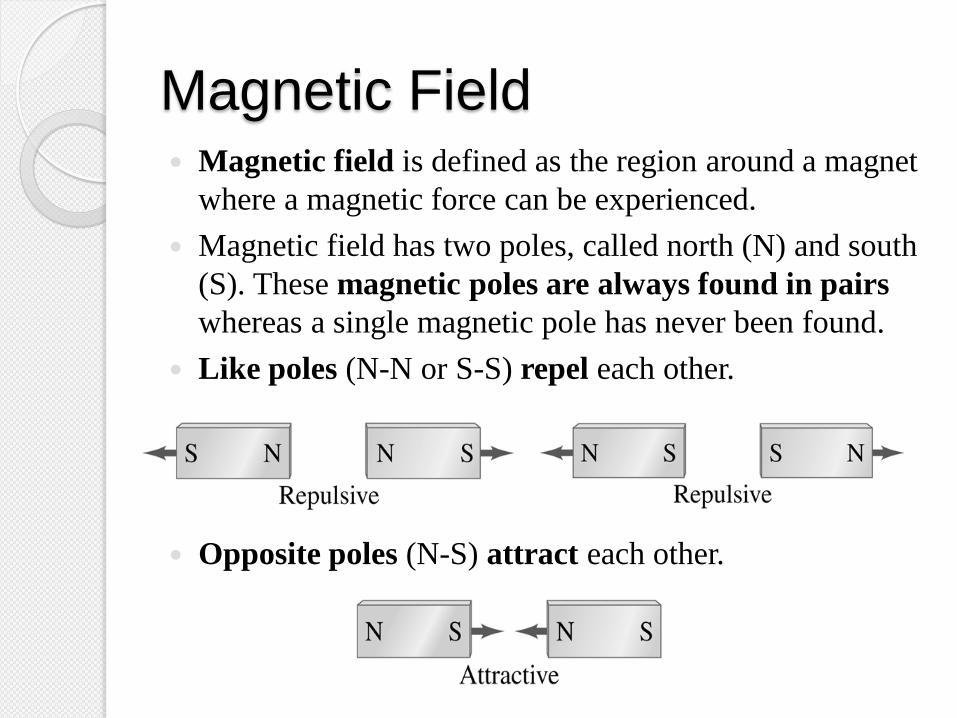
Magnetic Field Magnetic field is defined as the region around a magnet
where a magnetic force can be experienced.
Magnetic field has two poles, called north (N) and south
(S). These magnetic poles are always found in pairs
whereas a single magnetic pole has never been found.
Like poles (N-N or S-S) repel each other.
Opposite poles (N-S) attract each other.
Magnetic Field Sources and
Magnetic Field Lines
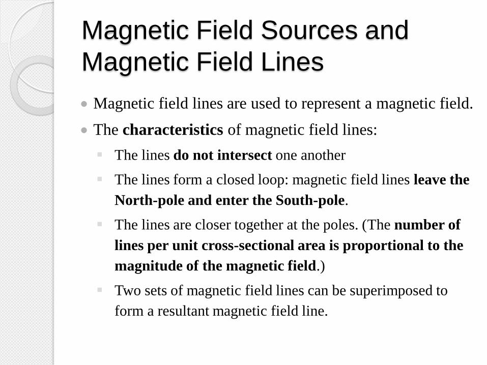
Magnetic field lines are used to represent a magnetic field.
The characteristics of magnetic field lines:
The lines do not intersect one another
The lines form a closed loop: magnetic field lines leave the
North-pole and enter the South-pole.
The lines are closer together at the poles. (The number of
lines per unit cross-sectional area is proportional to the
magnitude of the magnetic field.)
Two sets of magnetic field lines can be superimposed to
form a resultant magnetic field line.

Magnetic Field Sources and
Magnetic Field Lines
Magnetic field can be represented by crosses or by
dotted circles as shown in figures below:
Magnetic field lines
enter the page
perpendicularly
Magnetic field lines
leave the page
perpendicularly

Magnetic Field Sources and
Magnetic Field Lines The pattern of the magnetic field lines can be
determined by using two methods:
Using compass needles
Using sprinkling iron filings on paper
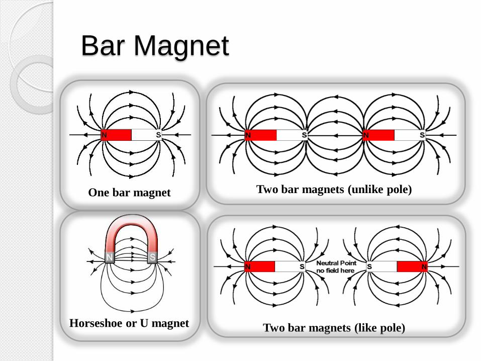
Bar Magnet
One bar magnet
Horseshoe or U magnet
Two bar magnets (unlike pole)
Two bar magnets (like pole)
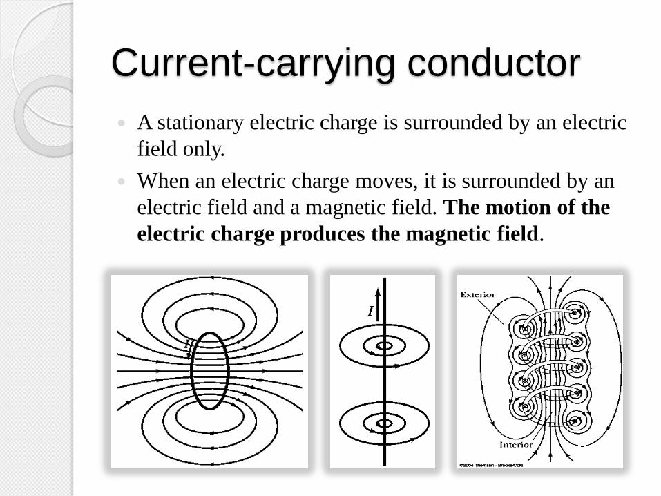
Current-carrying conductor
A stationary electric charge is surrounded by an electric
field only.
When an electric charge moves, it is surrounded by an
electric field and a magnetic field. The motion of the
electric charge produces the magnetic field.

Earth magnetic field
Note that the Earth’s
“North Pole” is really
a south magnetic pole,
as the north ends of
magnets are attracted
to it.

Example 1
a)
b)
N
N
S
S
N
N
S
S
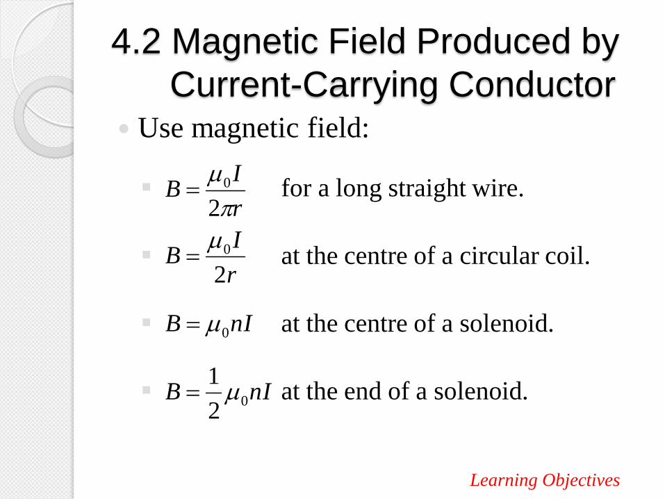
4.2 Magnetic Field Produced by
Current-Carrying Conductor Use magnetic field:
for a long straight wire.
at the centre of a circular coil.
at the centre of a solenoid.
at the end of a solenoid.
Learning Objectives
r
IB
2
0
r
IB
2
0
nIB 0
nIB 02
1

Types of Current-Carrying Conductors
1. A long straight wire
2. A circular coil
3. A solenoid

A Long Straight Wire
Direction: Right hand grip rule
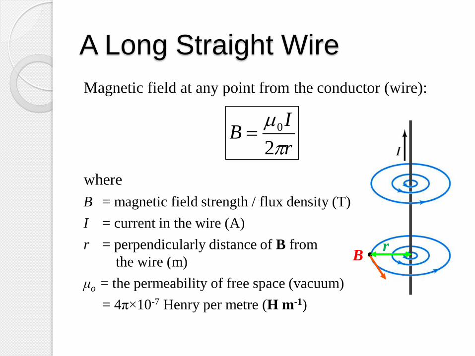
A Long Straight Wire
Magnetic field at any point from the conductor (wire):
where
B = magnetic field strength / flux density (T)
I = current in the wire (A)
r = perpendicularly distance of B from
the wire (m)
μo = the permeability of free space (vacuum)
= 4π×10-7 Henry per metre (H m-1)
r
IB
2
0
B • r

A Circular Coil
Direction:
Right hand
grip rule

A Circular Coil
Magnetic field at the centre of the circular coil :
where
R = radius of the circular coil.
µ0 = permeability of free space
4π × 10-7 H m-1
I = current
N = number of coils (loops)
R
IB
2
0
R
NIB
2
0
At the centre of
ONE circular coil
At the centre of N
circular coils
B
R

A Solenoid

A Solenoid
Direction:
Right hand grip rule
To determine the north pole
of the solenoid (/magnet)
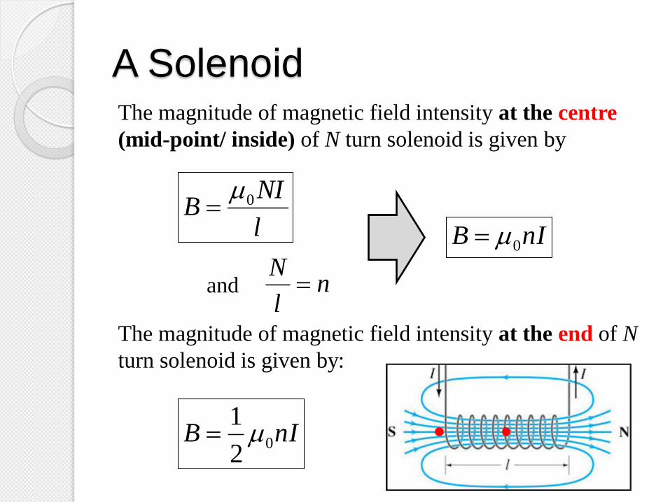
A Solenoid The magnitude of magnetic field intensity at the centre
(mid-point/ inside) of N turn solenoid is given by
The magnitude of magnetic field intensity at the end of N
turn solenoid is given by:
l
NIB 0
nIB 0
nl
Nand
nIB 02
1

Example 2
Determine the magnetic field strength at point X
and Y from a long, straight wire carrying a current
of 5 A as shown below.

Example 2 – Solution
Example 3
A circular coil having 400 turns of wire in air has
a radius of 6 cm and is in the plane of the paper.
What is the value of current must exist in the coil
to produce a flux density of 2 mT at its center?

Example 3 – Solution

Example 4
An air-core solenoid with 2000 loops is 60 cm
long and has a diameter of 2.0 cm. If a current of
5.0 A is sent through it, what will be the flux
density within it?

Example 4 – Solution

Example 5
A solenoid is constructed by winding 400 turns of
wire on a 20 cm iron core. The relative
permeability of the iron is 13000. What current
is required to produce a magnetic induction of 0.5
T in the center of the solenoid?

Example 5 – Solution N = 400, l = 0.2 m, B = 0.5 T, µr = 13000
1-2
7
0
m H 1063.1
10413000
r
A 015.0
2.0
4001063.15.0
2
I
l
NIB
Additional knowledge:
Iron-core solenoid has
stronger magnetic field
strength than air-core
solenoid because
the soft iron inside
the solenoid becomes
a magnet itself when
the current is flowing.
Bl
NIB ,

Example 6
Two straight parallel wires are 30 cm apart and
each carries a current of 20 A. Find the magnitude
and direction of the magnetic field at a point in the
plane of the wires that is 10 cm from one wire and
20 cm from the other if the currents are
a) in the same direction,
b) in the opposite direction.

Example 6 – Solution
a)
IX IY
0.3 m
0.2 m 0.1 m
A
IX IY
BX
BY
View from top
rX rY
A 20 III YX

Example 6 – Solution

Example 6 – Solution
b)
IX IY
0.3 m
0.2 m 0.1 m
A
x
IX IY
BX
BY
View from top
rX rY
A 20 III YX

Example 6 – Solution

4.3 Force on a moving charged particle
in a uniform magnetic field
Use magnetic force,
Describe circular motion of a charge in a
uniform magnetic field.
Use relationship
BvqF
CB FF
Learning Objectives

Force on a Moving Charged
Particle A stationary electric charge in a magnetic field will not
experience any force. But if the charge is moving with a
velocity, v in a magnetic field, B then it will experience
a force. This force known as magnetic force.
The magnitude of the magnetic force can be calculated by
using the equation below:
BvqF
sinqvBF
where
q : magnitude of the charge
θ : angle between v and B

Right Hand Rule
C
B
A +
IMPORTANT!
Thumb indicates the
direction of the
magnetic force exerted
on a positive charge.
If the charge is
negative, direction of
the force is opposite. Direction of the force
if the charge is
electron (negative)
BAC
First vector Second vector

Force on a Moving Charged
Particle The direction of the magnetic force can be determined by
using right hand rule:
F
B
v
IMPORTANT!
Thumb indicates the
direction of the
magnetic force exerted
on a positive charge.
If the charge is
negative, direction of
the force is opposite.
BvqF

Alternatively,
Fleming’s Hand
Rule
Right Hand
- Negative charge
- Electron
Left Hand
- Positive charge
- Proton
Thumb – direction of Force
First finger – direction of Field
Second finger – direction of Velocity.
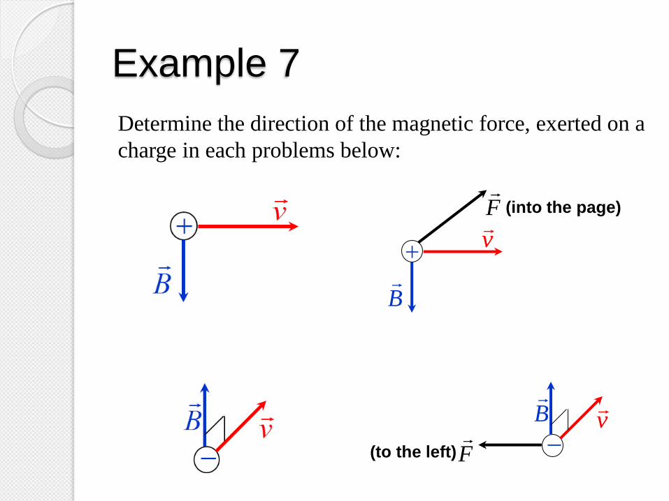
Example 7
Determine the direction of the magnetic force, exerted on a
charge in each problems below:
B
vF
(into the page)
B
v
F
(to the left)

Example 7
Determine the direction of the magnetic force, exerted on a
charge in each problems below:
B v
X X X X
X X X X
X X X X
F
(to the left)
v
I
F
(upwards)
B
X X
X
X
X
X
X X

Circular Motion of a Charge in a
Uniform Magnetic Field

Circular Motion of a Charge in a
Uniform Magnetic Field Consider a charged particle moving in a uniform
magnetic field with its velocity perpendicular to the
magnetic field.
As the particle enters the region, it will experience a
magnetic force which the force is perpendicular to the
velocity of the particle. Hence the direction of its
velocity changes but the magnetic force remains
perpendicular to the velocity.
Since the path is circle therefore the magnetic force FB
contributes the centripetal force Fc (net force) in this
motion. Thus
CB FF

Circular Motion of a Charge in a
Uniform Magnetic Field
CB FF
r
mvBqv
2
sin and θ = 90°
Bq
mvr
where m : mass of the charged particle
v : magnitude of the velocity
r : radius of the circular path
q : magnitude of the charged particle

Circular Motion of a Charge in a
Uniform Magnetic Field The period of the circular motion, T makes by the particle
is given by
The frequency of the circular motion makes by the
particle is given by
v
rT
2
Bq
mT
2
Tf
1
m
Bqf
2

Note!
Circular motion if v
is perpendicular to
B
90 90
Helical motion if v is
not perpendicular to B
Spiral if v is not
constant
Bq
mvr
vr
CB FF
Example 8
A charge q1 = 25.0 μC moves with a speed of 4.5×10³ m s-1
perpendicularly to a uniform magnetic field. The charge
experiences a magnetic force of 7.31×10⁻³ N. A second
charge q2 = 5.00 μC travels at an angle of 40.0 o with
respect to the same magnetic field and experiences a
1.90×10⁻³ N force. Determine
a. The magnitude of the magnetic field
b. The speed of q2.

Example 8 – Solution
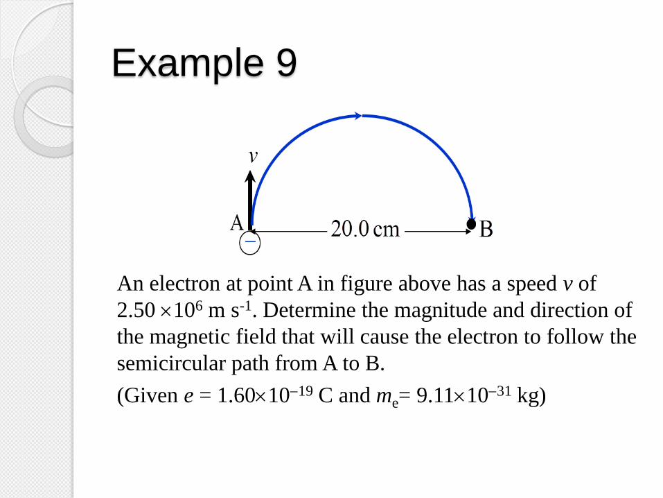
Example 9
An electron at point A in figure above has a speed v of
2.50 106 m s-1. Determine the magnitude and direction of
the magnetic field that will cause the electron to follow the
semicircular path from A to B.
(Given e = 1.601019 C and me= 9.111031 kg)
Example 9 – Solution

Example 9 – Solution

4.4 Force on a current carrying
conductor in a uniform magnetic field
Use magnetic force,
BlIF
Learning Objectives
Force on a Current-Carrying
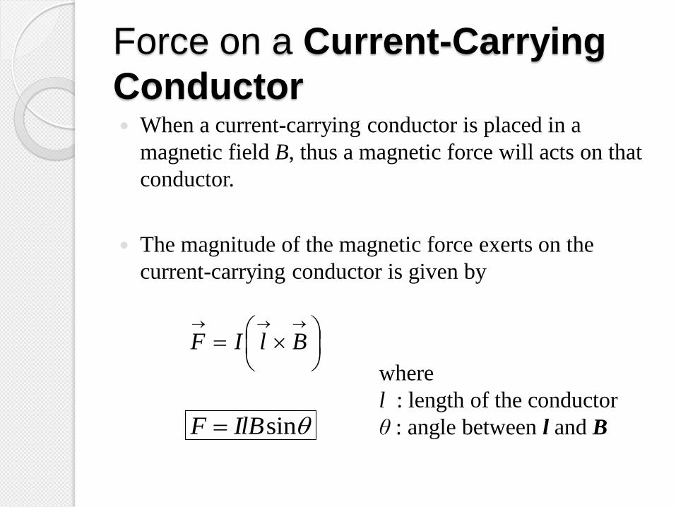
Conductor When a current-carrying conductor is placed in a
magnetic field B, thus a magnetic force will acts on that
conductor.
The magnitude of the magnetic force exerts on the
current-carrying conductor is given by
BlIF
sinIlBF
where
l : length of the conductor
θ : angle between l and B

Force on a Current-Carrying
Conductor
F
B
l
IMPORTANT!
vector l is the same as
the direction of the
current flows I through
the conductor.
BlIF

Example 10
Determine the direction of the magnetic force, exerted on a
conductor carrying current, I in each problems below.
B I
X X X X
X X X X
X X X X
F
(to the left)
B I
X X X X
X X X X
X X X X
F
(to the right)

Alternatively,
Direction of F can also be determined by using
Fleming’s Left Hand Rule
Thumb – direction of Force
First finger – direction of Field
Second finger – direction of Current.
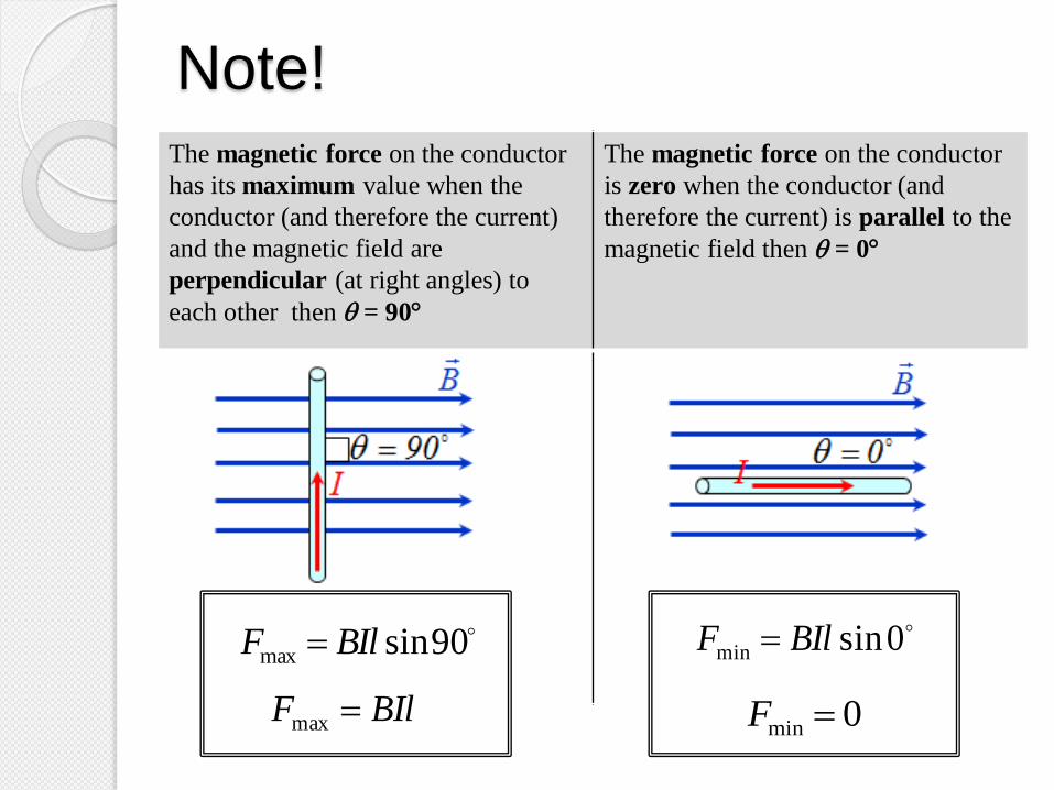
The magnetic force on the conductor
has its maximum value when the
conductor (and therefore the current)
and the magnetic field are
perpendicular (at right angles) to
each other then = 90
The magnetic force on the conductor
is zero when the conductor (and
therefore the current) is parallel to the
magnetic field then = 0
Note!
90sinmax BIlF
BIlF max
0sinmin BIlF
0min F
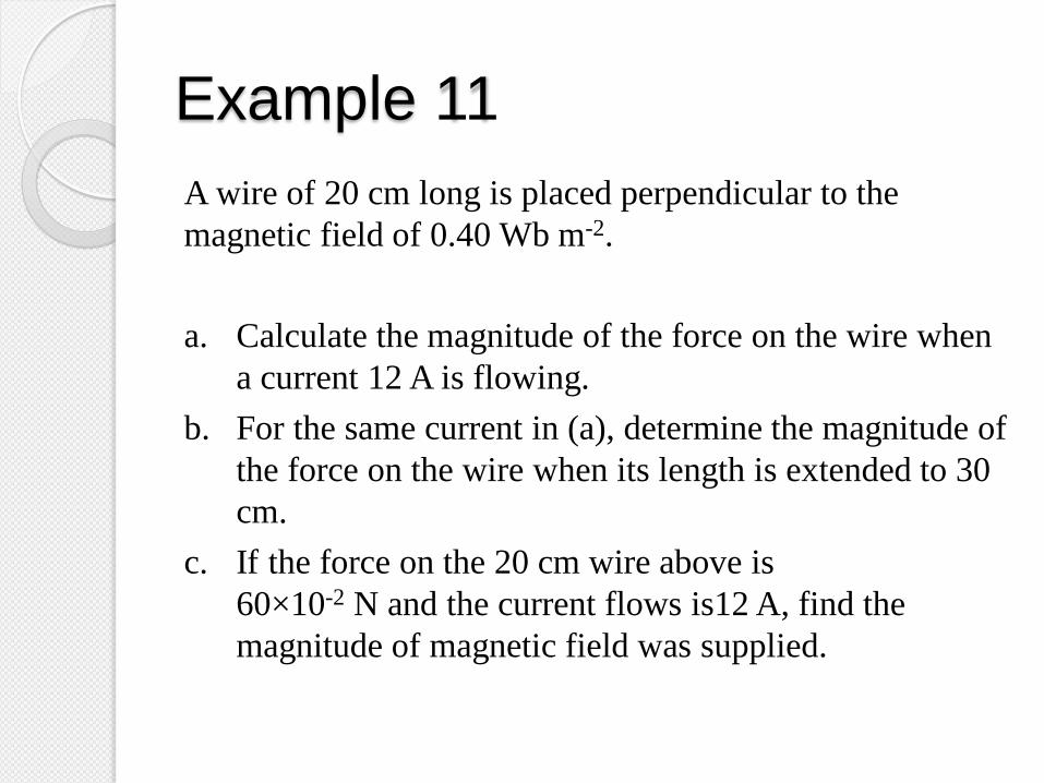
Example 11
A wire of 20 cm long is placed perpendicular to the
magnetic field of 0.40 Wb m-2.
a. Calculate the magnitude of the force on the wire when
a current 12 A is flowing.
b. For the same current in (a), determine the magnitude of
the force on the wire when its length is extended to 30
cm.
c. If the force on the 20 cm wire above is
60×10-2 N and the current flows is12 A, find the
magnitude of magnetic field was supplied.

Example 11 – Solution

Example 11 – Solution

Example 12
A square coil of wire containing a single turn is placed in a
uniform 0.25 T magnetic field. Each side has a length of
0.32 m, and the current in the coil is 12 A. Determine the
magnitude of the magnetic force on each of the four sides.
90o B
I

Example 12 – Solution

4.5 Forces between two parallel
current carrying conductors
Derive magnetic force per unit length of
two parallel current carrying conductors.
Use magnetic force per unit length,
Define one ampere.
d
II
l
F
2
210
Learning Objectives
Forces Between Two Parallel
Current Carrying Conductors
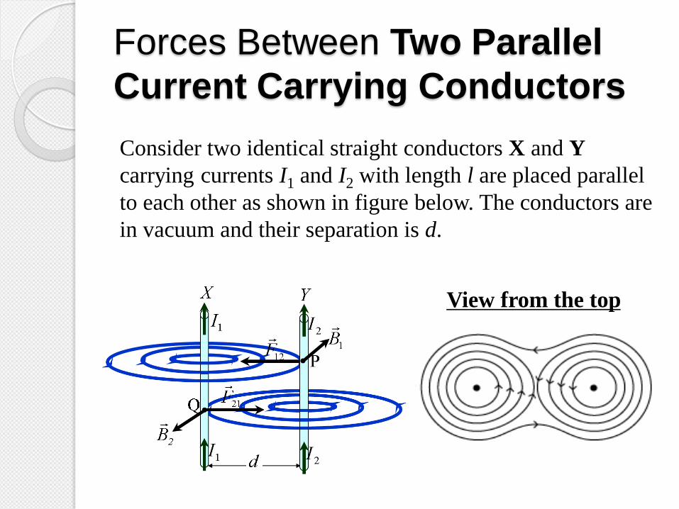
Consider two identical straight conductors X and Y
carrying currents I1 and I2 with length l are placed parallel
to each other as shown in figure below. The conductors are
in vacuum and their separation is d.
View from the top

Problem Solving Strategy
Step 1
Determine the direction of the
magnetic flux density due to
the neighbouring current-
carrying conductor
Step 2
Determine the direction of the
magnetic force acting on the
current-carrying conductor
(object)
d
2I
2I
1I
1I
X Y
Q
d
2I
2I
1I
1I
X Y
Q F
B B

Force exerted on conductor X
The magnitude of the magnetic flux
density, B2 at point Q on conductor
X due to the current in conductor Y
is given by:
d
IB
2
202
Direction: out of the page
Conductor X carries a current I1 and in the magnetic field B2
then conductor X will experiences a magnetic force, F21.
The magnitude of F21 is given by
sin1221 lIBF
90sin2
120
21 lId
IF
lI
d
IF 1
2021
2
Direction:
towards
conductor Y

Force exerted on conductor Y
The magnitude of the magnetic flux
density, B1 at point P on conductor
Y due to the current in conductor X
is given by
d
IB
2
101
Direction: into the page
Conductor Y carries a current I2 and in the magnetic field B1
then conductor Y will experiences a magnetic force, F12.
The magnitude of F12 is given by
sin2112 lIBF
90sin2
210
12 lId
IF
lId
IF 2
1012
2
Direction:
towards
conductor X
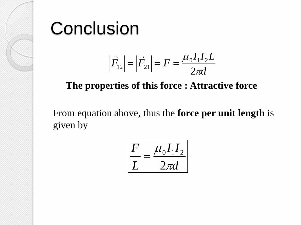
Conclusion
From equation above, thus the force per unit length is
given by
d
LIIFFF
2
2102112
The properties of this force : Attractive force
d
II
L
F
2
210

Forces Between Two Parallel
Current Carrying Conductors If the direction of current in conductor Y is change to
upside down as shown in figure
The magnitude of F12 and F21 can be determined by using
equations above and its direction by applying right hand
rule.
View from the top
Conclusion: Type of the force is repulsive force
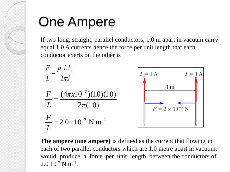
One Ampere If two long, straight, parallel conductors, 1.0 m apart in vacuum carry
equal 1.0 A currents hence the force per unit length that each
conductor exerts on the other is
The ampere (one ampere) is defined as the current that flowing in
each of two parallel conductors which are 1.0 metre apart in vacuum,
would produce a force per unit length between the conductors of
2.0 10-7 N m-1.
d
II
L
F
2
210
17 m N 100.2 L
F
)01(2
)01)(01)(104( 7
.π
..πx
L
F
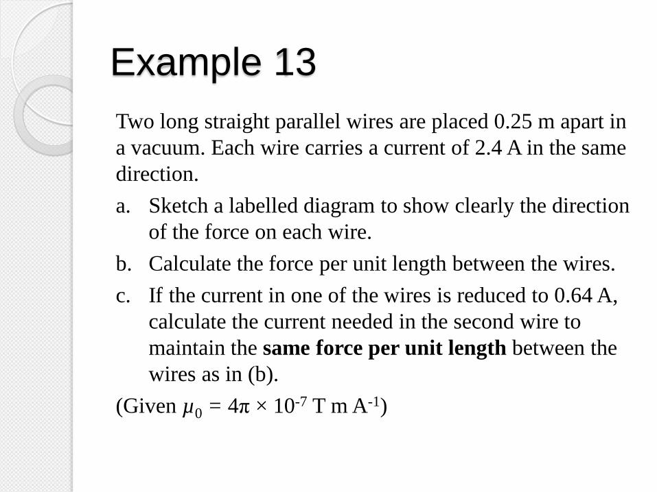
Example 13
Two long straight parallel wires are placed 0.25 m apart in
a vacuum. Each wire carries a current of 2.4 A in the same
direction.
a. Sketch a labelled diagram to show clearly the direction
of the force on each wire.
b. Calculate the force per unit length between the wires.
c. If the current in one of the wires is reduced to 0.64 A,
calculate the current needed in the second wire to
maintain the same force per unit length between the
wires as in (b).
(Given µ0 = 4π × 10-7 T m A-1)

Example 13 – Solution

Example 13 – Solution

4.6 Torque on a Coil
Use torque,
where N = number of turns
Explain the working principle of a moving
coil galvanometer.
BANI
Learning Objectives
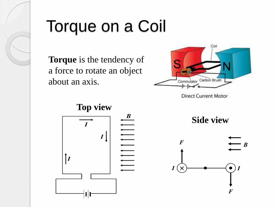
Torque on a Coil
Top view
Side view
Torque is the tendency of
a force to rotate an object
about an axis.
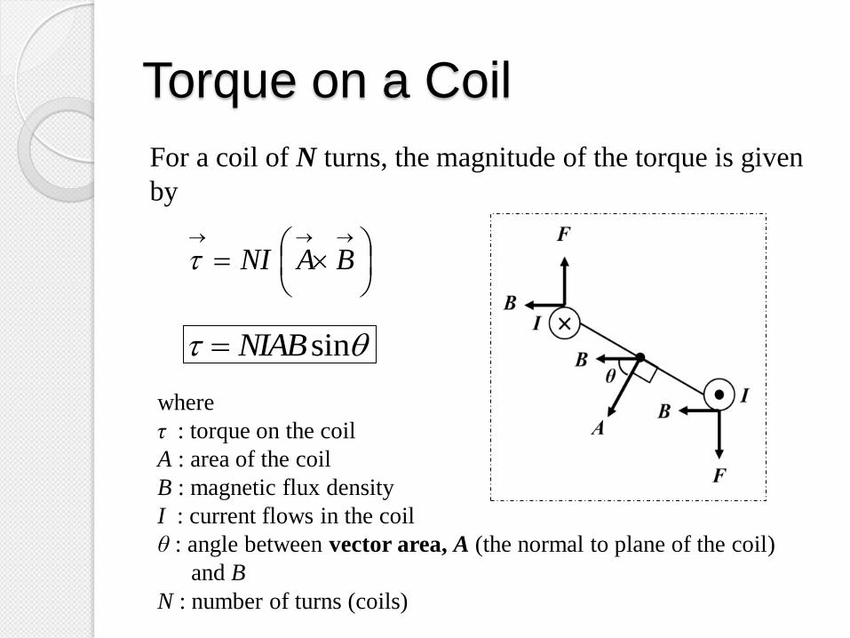
Torque on a Coil
For a coil of N turns, the magnitude of the torque is given
by
BANI
sinNIAB
where
τ : torque on the coil
A : area of the coil
B : magnetic flux density
I : current flows in the coil
θ : angle between vector area, A (the normal to plane of the coil)
and B
N : number of turns (coils)

Note!
The torque is zero when θ = 0˚ and is maximum when θ = 90˚ as
shown in figures below.
0sinNIABτ
0τ
90sinNIABτ
NIABτ

The Working Principles of a
Moving Coil Galvanometer

The Working Principles of a
Moving Coil Galvanometer
The galvanometer is the main component in analog
meters for measuring current and voltage.
It consists of a magnet, a coil of wire, a spring, a pointer
and a calibrated scale.
The coil of wire contains many turns and is wrapped
around a soft iron cylinder.

N S
The Working Principles of a
Moving Coil Galvanometer
The coil is pivoted in a radial magnetic field, so that no
matter what position it turns, the plane of the coil is
always parallel to the magnetic field.

The Working Principles of a
Moving Coil Galvanometer
The basic operation of the galvanometer uses the fact
that a torque acts on a current loop in the presence of a
magnetic field.
When there is a current in the coil, the coil rotates in
response to the torque (τ = NIAB ) applied by the
magnet.
This causes the pointer (attached to the coil) to move in
relation to the scale.

The Working Principles of a
Moving Coil Galvanometer
The torque experienced by the coil is proportional to the
current in it; the larger the current, the greater the torque
and the more the coil rotates before the spring tightens
enough to stop the rotation.
Hence, the deflection of the pointer attached to the coil
is proportional to the current.
The coil stops rotating when this torque is balanced by
the restoring torque of the spring.

The Working Principles of a
Moving Coil Galvanometer
From this equation, the current I can be calculated by
measuring the angle θ.
constant) (torsional spring theofconstant stiffness theis where
torquerestoringforce magnetic todue Torque s
k
NAB
kI
kNIAB
coil theof anglerotation :θ radianin

Example 14
A 20 turns rectangular coil with sides 6.0 cm x 4.0 cm is
placed vertically in a uniform horizontal magnetic field of
magnitude 1.0 T. If the current flows in the coil is 5.0 A,
determine the torque acting on the coil when the plane of
the coil is
a. perpendicular to the field,
b. parallel to the field,
c. at 60 to the field.

Example 14 – Solution

Example 14 – Solution

4.7 Motion of charged particle in
magnetic field and electric field
Explain the motion of a charged particle
in both magnetic field and electric field.
Derive and use velocity, in a
velocity selector.
B
Ev
Learning Objectives

Velocity Selector
Velocity selector consists of a pair of parallel metal plates
across which an electric field can be applied in uniform
magnetic field.
Consider a positive charged particle with mass m, charge q
and speed v enters a region of space where the electric and
magnetic fields are perpendicular to the particle’s velocity
and to each other as shown in figure above.

Velocity Selector
The charged particle will experiences the electric force FE is
downwards with magnitude qE and the magnetic force FB is
upwards with magnitude Bqv as shown in figure above.
If the particle travels in a straight line with constant velocity
hence the electric and magnetic forces are equal in
magnitude (dynamic equilibrium). Therefore
EB FF
qEqvB 90sin
B
Ev
Only particles with velocity
equal to E/B can pass through
without being deflected by the
fields. Equation above also
works for electron or other
negative charged particles.
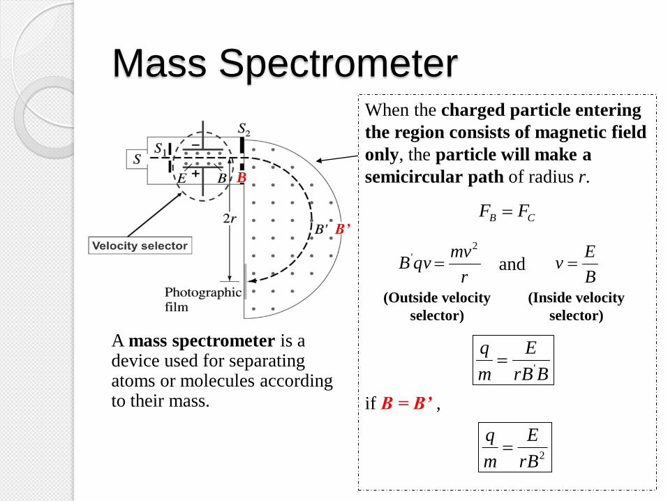
Mass Spectrometer When the charged particle entering
the region consists of magnetic field
only, the particle will make a
semicircular path of radius r.
and
if B = B’ ,
CB FF
r
mvqvB
2'
B
Ev
BrB
E
m
q'
A mass spectrometer is a device used for separating atoms or molecules according to their mass.
2rB
E
m
q
B
B’
(Outside velocity
selector)
(Inside velocity
selector)

Example 15
A velocity selector is to be constructed to select ions
(positive) moving to the right at 6.0 km s-1. The electric
field is 300 V m-1 upwards. What should be the magnitude
and direction of the magnetic field?

Example 15 – Solution

Example 16
An ion enters a uniform magnetic field B. The path of the
ion is a spiral as shown in the figure.
a. Determine whether the ion is positively or negatively
charged.
b. Give reasons for the shape of the path.
Example 16 – Solution

Summary Magnetic Field
Magnetic Field
Produced by
Current-Carrying
Conductor
Magnetic Force Torque Sources and
Magnetic Field
Lines
Motion of
Charge in
Magnetic and
Electric Field
Moving
Charge Current-
Carrying
Conductor
Two
Parallel
Conductors
Straight
Wire
Circular
Loop Solenoid