Embed Size (px)
Citation preview

CHAPTER 4
LOCATION
SURVEYS
Chapter Contents
Sec. 4.01 General Remarks
Sec. 4.02 Survey Assignment
Sec. 4.03 Contacting Property Owners
Sec. 4.04 Horizontal Control Monumentation
Sec. 4.05 Alignment
Sec. 4.06 Field Data
Sec. 4.07 Topography
Sec. 4.08 Property Data and Right-of-Way
Sec. 4.09 Procedures For Locating Existing Underground
Utilities
Sec. 4.10 Levels
Sec. 4.11 Cross-Sections & DTMs
Sec. 4.12 Bridge Site Plans - Streams
Sec. 4.13 Bridge Site Plans - Highways & Railroads
Sec. 4.14 Bridge Site Plans - Widening
Sec. 4.15 Minimum Plan Projects
Sec. 4.16 Additional Survey Data Requests
Sec. 4.17 Submission Of The Survey Report
Sec. 4.18 Digital Sealing Of Microstation And Adobe Files

4-1
Sec. 4.01 General Remarks
In using these instructions, it must be realized that to write a set of rules as all-inclusive
as to cover any and all situations encountered during the course of a survey would be
impractical, if not impossible. Unusual situations will occur, and we depend on the skill and
initiative of the Consultants, District Survey Managers and staff to resolve, or have these
situations resolved. State Survey Personnel or Consultants will make all location surveys, using
current guidelines and instructions, from the Virginia Department of Transportation’s "Survey
Manual". This manual will cover almost all policies and procedures concurrent with a location
survey.
Sec. 4.02 Survey Assignment
Upon receipt of a survey authorization, the District Survey Manager will assign the
project to a Survey Party Manager (Land Surveyor) in the district or Consultant staff (see Sec.
1.02.2). During the progress of the survey, the District Survey Manager will review the work for
conformance with current instructions and ascertain that the survey data is complete and covers
the proposed project.
Sec. 4.03 Contacting Property Owners
In making surveys of any nature, survey party personnel usually are the first agents or
representatives of the Department to encounter private property owners. Since first impressions
often are lasting ones, it is of utmost importance that all contacts with private property owners be
handled with integrity and in a courteous and business-like manner.
Every possible effort must be made by the survey party to contact property owners prior
to entering their property. Although law prescribes our right of entry for making surveys,
(See Sec. 1.01) courtesy demands that this right must not be abused. There can be no reasonable
excuse for the failure to make these contacts, particularly when the owner lives on the property
or in the vicinity.
Prior to any fieldwork involving private property or public utility property, the Survey
Party Manager (Land Surveyor), staff, or consultants should visit the appropriate courthouse to
view area real estate maps for the purpose of making a list of all property owners to be effected
by the proposed survey. In areas where real estate maps are not available, other methods will be
necessary to determine the effected properties.
This list should then be forwarded to the District Survey Manager, and the standard
memorandum shown on Figure 4-A of this manual prepared for each owner. As of July 1, 2011,
a letter will be sent to all affected landowners on a project. The surveyor cannot enter the
property until fifteen (15) days after the letter is received. This memorandum will be used
statewide to insure uniformity because this is a law Section 33.2-1011. The memorandum must
state the survey task and the duration of the assignment if it exceeds 90 days. Note: The
duration must have specific dates and cannot cover the life of the project.
Rev. 1/13

4-2
If the survey task is going to exceed the duration indicated on the initial letter, another
memorandum will need to be sent 15 days prior to the end of the initial letters date. Survey
updates cannot be included in initial memorandum duration. Update surveys will trigger another
memorandum letter to each landowner. The brochure "Let's Take a Look" must be sent with this
memorandum.
The Survey Party Manager (Land Surveyor) or consultant should deliver personally or by
mail a copy of this memorandum, a list of parcels affected(list each parcel by address or tax id
number) and brochure to each property owner affected. In either case, a copy should be
furnished to the Resident Engineer and/or Project Manager with a list of all property owners for
which a memorandum and brochure was prepared. This will enable the Resident Engineer
and/or Project Manager to be better prepared to handle inquiries that may be made as the survey
progresses.
The Survey Party Manager or Consultants should also keep with him, or in his vehicles, while
making a location survey, extra copies of this memorandum and brochure, if for any reason some
property owner may have not received the memorandum and brochure.
Sec. 4.04 Horizontal Control Monumentation
Permanent Horizontal Control Monuments shall be set on all surveys for highways for all
systems, including closed surveys. Data available for setting horizontal control will be sent with
the survey authorization, or as schedules permit the Global Positioning System (GPS) will be
initiated by the State Survey Program Manager with the authorization memorandum. The
District Survey Manager will assure that the Survey Party Manager (Land Surveyor) has
sufficient data for control and/or will coordinate with the State Geodetic Survey Engineer the
scheduling for setting GPS datum and will provide sufficient personnel to assist the State
Geodetic Survey Engineer when securing GPS datum.
Standard VDOT disks are to be set in concrete with re-bar or other metal added to assist
in relocation with a metal detector (see Figure 10-D). In addition to permanent monuments,
additional swing ties to other objects should be obtained as evidence for re-establishment of a
monument. A minimum of four (4) monuments should be set on each project regardless of the
length of the project.
Monuments should be tied to the location centerline or baseline by right angle plus and
distance and enough monuments placed that the alignment can be re-established readily, with
State plane or project coordinate values shown to the nearest one thousandth foot (0.001-ft) and
vertical control to the nearest one hundredth foot (0.01-ft). The maximum error for vertical
control shall in no case be greater than plus or minus five hundredths foot (±0.05-ft) times the
square root of the loop distance in miles.
Rev. 7/15

4-3
Form LD-200 (Horizontal Control Reference Card) (Figure 10-F) shall be completed for
all permanent monuments set for horizontal control, for referencing purposes. When the cards
have been completed by VDOT personnel or consultants, a copy will be sent to the State
Geodetic Survey Engineer and the appropriate District immediately upon completion of the
control.
Sec. 4.05 Traverse alignments or baselines and Datum
The traverse alignments (legacy) or baselines should be established to be functional
relative to the safety and geometric alignment of the survey corridor of the project.
Any new survey, that will not be tied into any existing VDOT survey projects, shall be
tied to the Virginia State Plane Coordinate System, North American Datum of 1983
(Current Published Adjustment) Datum, horizontally, and North American Vertical Datum
of 1988 (NAVD 88) vertically. The Global Positioning System (GPS) should be utilized
whenever it is practical to do so. Unless specifically directed by the State Survey Program
Manager, any survey that is an extension of, or will tie into, an existing VDOT survey project
will be constrained to the datum of the existing survey project. The State Survey Program
Manager or State Geodetic Survey Engineer will furnish all N.G.S. (formerly U.S.C. & G.S.)
control data in the area of the survey when the survey is authorized. The use of assumed vertical
is not acceptable.
In the establishment of the survey traverse alignments, the distance and angular
measurement methods or procedures shall be commensurate with the degree of accuracy
required. All alignment computations (curve data) must be calculated to the fourth decimal place
and shown to the nearest one-hundredth foot (0.01-ft). A single traverse line or baseline for the
measurement of cross-sections is desirable in the development of computerized design and
earthwork. In proposed dual lane situations, the one traverse line should be located so that
readings may be obtained and full coverage of both lanes recorded.
Traverse baselines or traverse alignments will be included in a VDOT Survey file and
will be entered according to the VDOT CADD Standards. All traverse closures will be reported.
The CADD Standards are included in Chapter 2 of the CADD manual. All text, levels, weights
and line styles entered into a survey file will adhere to these standards. The file standards
presently being used by VDOT are shown in the CADD manual.
Legacy survey alignment stationing should begin with a station not less than 10+00 (Feet) and
increase from the South to the North or from the West to the East. If the new stationing
conflicts with the stationing of a previously constructed project within the limits of the new
survey or if the survey is the extension of a previous survey, the old stationing shall be carried
forward.
Minus stations and overlapping equalities are not to be used. Equalities in stations
should be avoided wherever possible. If an overlapping equality occurs, the AHD (Ahead)
station shall be increased by 1000.
Rev. 3/14

4-4
When alternate lines are necessary, their stationing shall be a continuation of the
stationing of the original line and a stationing equality shall be shown at the tie-in. Each
alternate line shall be clearly designated if adopted. When a survey line intersects or is within a
reasonable distance of a previous survey, the lines should be tied together at frequent intervals.
When terrain, property developments or other conditions make it desirable to parallel a
right-of-way owned by any public utility company, special attention must be given to positioning
the line so as to avoid encroachment of the proposed highway right-of-way on that owned by the
utility company.
In making surveys from mosaics furnished by the Location and Design Division, any
change in topography, or other features which do not show on the mosaic and which might have
an adverse effect on the ultimate location, should be brought to the attention of the District
Survey Manager. If a decision to change the proposed line is made, this should be fully
explained in the Survey Report.
Alignments for all intersecting roads should be run out a sufficient distance from the
survey traverse line, depending upon the nature of the possible changes, to ensure the securing of
all needed information. Complete survey information - topography, property lines, property
owners, DTM’s, etc. - should be secured for the full length of the connection. When a large
skew angle is encountered, consideration should be given to relocate to a more desirable inter-
secting angle.
Alignment for grade separation structures of railroads should cross the railroads at right
angles whenever possible. When a skew crossing is necessary, the skew should be at even
fifteen-degree (15°) skew angle increments, unless conditions make other angles necessary.
When conditions warrant the use of other angles, the angles should be to the nearest even degree.
The skew angle is not to exceed forty-five degrees (45°). The distance between the P.C. or P.T.
of a curve and the structure should be sufficient to permit using the standard length transition
without overlapping the bridge where possible. A centerline tie must be made with the railroad
by measuring the angle of intersection. Track alignment on the railroad shall be run for a
distance of five hundred feet (500 ft) each side of the centerline, down the center of the tracks.
When the railroad is on a curve, the track alignment should be run out as a regular traverse, with
each chord point used as a point of intersection. These angular measurements must be taken and
recorded to the nearest thirty seconds (30”).
Alignments for construction centerlines shall be shown on all plan sheets, bridge
situations, and/or site plans, closed survey plats or any other surveys. All plus and offsets will be
referenced from the construction centerline.
Generally, long easy curves that do not materially lengthen the route are preferred to a
continuous tangent alignment. Long curves that fit the topography of the country are preferable
to shorter curves and longer tangents. Short, sharp curves and steep grades near the approach to
a bridge and sharp curves at the foot of a steep descending grade are particularly hazardous and
should be avoided.

4-5
A combination of horizontal and vertical curvature at a summit should be avoided. It is
highly desirable for safety reasons to arrange groups of curves in orderly sequence form flat to
sharp and back to flat, using the easiest possible curves at the ends of long tangents. Curvature
should not be misleading to motorists by sudden variation of degree. At all times, the flattest
curvature practical should be used.
On all location surveys, simple curves shall be located with sufficient distance between
the P.T. of one curve and the P.C. of the next to permit the use of standard length transition
spirals. Where it is impossible to meet this requirement, curves should be compounded or
reversed and made as near the same degree as practicable.
For small angles, the curve must always be of sufficient length to avoid the appearance of
a kink in the alignment.
When it is necessary to introduce curvature on the approach to a bridge, the P.C. or P.T.
of such curves shall be located, if possible, so that the standard length transition spiral will not
overlap the structure. If this is impossible, then consideration should be given to putting the
structure entirely on the circular part of the curve.
Sec. 4.06 Field Data
All field data will be secured by GPS RTK, Mobile scanning, Robotic total station, or
Total Station Survey methods and processed in accordance with the procedures outlined in this
manual. This information should be complete and will be used to prepare finished plan base.
Sec. 4.07 Topography
Topography will be secured by the use of Total Survey Station, mobile scanning, and/ or
Photogrammetric methods and procedures. The procedures and standards for creating Survey
CADD files are explained in Chapter 2 of the CADD manual. The Survey CADD Section has
made a conscious effort in creating unique cells, levels, and linestyles for topography and utilities
that may be encountered by a survey party or consultant staff. Examples of these cells and
linestyles are also included in Appendix A of the CADD manual. It is required that these levels,
cells and linestyles be used in all VDOT survey files.
Topography (General) The location of edges of pavement, shrubbery, walls, curbs, fire hydrants, water meters,
right-of-way monuments and project markers shall be shown. Fences, streams, woods, outlet
ditches, entrances, roads, bridges, culverts, pipes, end walls, et cetera will also be shown.
Existing pipe sizes should be accurately measured.
The sizes of trees will be measured 4.5 feet above the ground, or Diameter at Breast
Height (DBH), to obtain the diameter of the tree. Isolated or cultivated trees should be located
and described.
Rev. 3/14

4-6
The outside limits of all automobile graveyards will be shown.
All types of fences, whether barbed wire, woven wire, rail, board, or other should be
shown and noted.
The extremities of cemeteries must be shown. The graves closest to centerline must be
shown and the approximate number of graves noted.
The width and type of pavement shall be shown. If concrete pavement has been overlaid
with asphalt, this shall be noted along with the approximate depth of the overlay. All changes of
pavement type must be referenced to survey stations.
Once an environmental scientist has marked the limits of wetland areas, the flags shall be
located and stored in a separate file. The file will be named “swlUPC#.dgn”. This data will not
be merged in the survey master file. The data shall be shown in the wetland file on appropriate
level and the scale shall be the job scale. This information is listed in Chapter 2 of the CADD
Manual.
Unusual circumstances such as standing water, sinkholes, caves, outcrops, or any other
condition which might need special attention from materials investigation should be noted by the
District Survey Manager or Survey Party Manager (Land Surveyor) in the Survey Report letter.
House & Building Location Buildings are to be shown at the overhang and the type of construction should be noted
(frame, brick, etc.), the height (one story, two story, etc.) and condition other than good, should
also be noted. Porches, carports are also to be shown.
Individual house numbers, where assigned, are to be shown in lieu of block numbers in
cities, towns, and built-up areas. Where house numbers have not been assigned, the block
numbers should be prominently shown. The building number should be shown within the limits
of the building, if possible. If this is not practical, the building number should be shown as close
to the building as possible.
Utilities & Drainage Items The location of utility poles and pedestals along with the number and utility owner
initials (C&P#100, V.P.#200A) should be shown. Overhead utility lines, except for high voltage
transmission lines, need not be shown unless requested by the utility engineer after the utility
field inspection. Underground utilities such as water and gas lines, telephone cables, etc. will be
addressed in Section 4.09 of this manual.
Storm and sanitary sewers are to be located with elevations secured on the tops of
manholes or drop inlets and their inverts (or flow lines). The location of the next structure
(manhole, etc.) outside of survey limits shall be included with elevations. Also, the open ends of
Rev. 3/14

4-7
pipes shall have their locations with invert elevations secured by the field parties. All municipal
sanitary sewer will be placed in the utility file(suUPC#).
Descriptions for drainage items shall be shown in accordance with the following:
Pipe Culverts
1. Diameter of culverts shall be shown to the nearest .1’.
2. Invert elevations shall be shown to the nearest 0.01 ft.
Storm Sewer
1. Diameter of culverts shall be shown to the nearest .1’.
2. Invert elevations shall be shown to the nearest 0.01 ft.
3. Heights of manholes and drop inlets shall be shown to nearest 0.01 ft.
Channels & Ditches
1. Show width and depth to the nearest 0.25 ft.
2. If a stream is three (3) or more feet wide, four breakline should be used for a more
accurate depiction of the stream.
Pipe Cover
1. Pipe Cover shall be shown to the nearest 0.25 ft.
The necessity for outlet ditches and channel changes should be investigated and appropriate
recommendations made. Any lake or pond being affected by possible erosion should be shown.
Wells, Springs, Septic Tanks & Drain fields
Except in areas where properties are served by municipally owned sewer and water
systems, information shall be shown on each individually developed property regarding water
supply and sewage disposal. If it is determined that the facilities will be impacted by future
construction, it will be necessary to accurately locate these facilities, and a specific request, to do
so, will be issued. If the facilities are a considerable distance from centerline, a note indicating
how these properties are served will suffice. Most often, the location of the facilities should be
shown in the survey file based upon the best data available. It should be noted that obtaining
location information from the counties might need to be addressed via the Freedom of
Information Act.
Historical Markers Historical markers should be located and the identifying number recorded. In the
securing of location survey data on any type of survey, special attention should be given to any
site that is of historical or archeological significance. Some of these sites are well marked and
are easily identifiable by markers placed by the Association for the Preservation of Virginia
Antiquities, the Virginia Department of Conservation and Economic Development or by local
governments. Some are not so well marked and require knowledge of the area and local research
Rev. 3/14

4-8
on the part of the Survey Party Manager (Land Surveyor). If there is any possibility that a site of
historical or archeological significance exists in the area of any survey, it should be
conspicuously noted in the Survey Report.
Hazardous Material/Waste Sites
Prior to Field Inspection the Project Manager will request that the District Environmental
Manager provide any known areas of significant contamination. The Office of Safety
and Health will be requested to provide recommendations for safety precautions to
protect the surveyors.
All hazardous material/waste (or potential) sites should be located and/or identified.
Caution should be taken and at no time should Department employees touch, smell, move or
otherwise be exposed directly to a potential hazardous material. Location and Design Division
staff should assist in the identification of any known or potentially contaminated sites early in the
project development stage. The Survey Party Manager (Land Surveyor) shall make a statement in
the Survey Report indicating whether any hazardous materials were encountered or found, and if
encountered or found, state the location of the possible hazard in the survey notes.
The survey party will note features such as:
Storage tanks (above-ground and underground)
Environmental monitoring wells (marked “Monitoring Well” and stick up well casings)
Oil/water separators
Dumping areas
Drums
Waste lagoons
Obvious surface contamination (e.g. staining and odors)
Obvious surface water contamination (e.g. oil sheen)
o The route survey will include notes of any potential sites or conditions identified by the
survey party.
o Areas of contamination, as provided by the District Environmental Manager, are to be shown
on the plan sheet (hatching, crosshatching, etc.).
o The Project Manager, with the assistance of the Survey Manager, should communicate the
findings of the route survey where potential contamination sites were identified, to the
District Environmental Manager for further review.
o Based on the evaluation and recommendations of the District Environmental Section,
avoidance of potential hazardous materials sites should be the first alternative design
consideration.
o When the selection of other location/design alternatives is not feasible, project designs that
minimize the impact of any hazardous materials site are to be evaluated.
Rev. 4/14

4-9
o If stormwater basins or conveyances are proposed for locations within known or potential
areas of contamination, coordinate with the District Environmental Manager to determine
ways to avoid impacts and prevent the contamination of groundwater and surface water
through such stormwater systems. Avoidance measures such as relocations, redesign to
reduce cut, etc. are to be considered. If avoidance is not feasible, methods for preventing the
spread of contamination are to be considered.
o The Project Manager will communicate to District Environmental Manager any substantial
changes in grades, alignment, stormwater management features and subsurface utilities,
especially those changes made late in project development.
Listed below are some sources which have potential for hazardous material waste from
underground tanks or associated sources. This is a partial list and should not be taken as all
inclusive. The surveyor should use common sense as well as research information as well as their
working knowledge of the areas to be surveyed in order to determine sites with potential
underground tanks.
Possible Underground Tank Locations:
Airports Auto Dealers and Repair Shops
Banks Car washes
Churches and/or cemeteries Colleges/Schools/Education Facilities
Construction Companies Government Services Offices
(Fire and Police Dept., Prisons, etc.) Convenience Stores
Delivery Services (UPS, FedEx, etc.) Distribution Companies
Dry Cleaners Engraving Firms
Farms Federal and State Government
Home Owners Hospitals and Nursing Homes
Hotels/Motels Grocery Stores
Installations and Offices Jobber Bulk Terminal
Manufacturing Plants Marinas
Mining Companies Recreational Facilities
Residential Apartment Buildings Restaurants
Service Stations Shopping Centers
Tire Stores Transportation Services
Truck Stops Trucking Firms
Utility Companies
Rev.4/14

4-10
Soils
The following sites have the potential of contaminating the surrounding soil: dumps,
waste water treatment sites, abandoned lagoons, landfills, dry cleaners, funeral homes, service
stations, vehicle maintenance areas, paint companies, photography labs, machine shops, medical
facilities, printing companies, pesticide operations, fertilizer operations, paper industries, electric
companies (storage yards), chemical manufacturing facilities, electronic facilities, wood
treatment plants (creosote or salt).
Signs The location and description of all special signs, such as overhead truss signs, electrical
traffic signal lights, railroad protective devices, traffic light actuating treadles etc., should be
shown in detail. On all surveys, the survey party should show all outdoor advertising signs and
indicate the O.A. license number, the size of the sign and the owner.
Government Control All government benchmarks, triangulation stations, traverse stations, azimuth marks,
reference marks, etc., must be located. If anticipated construction will disturb or destroy these
control markers, the disk number should be recorded and sent to the State Geodetic Engineer.
The State Geodetic Engineer will request a new disk from the appropriate agency. The State
Geodetic Engineer will coordinate the replacement of the mark with the District Survey Manager
using VDOT or consultant staff. The removed original disk and the new description and values
of the reset mark are to be sent back to the federal agency concerned.
Railroads When railroads parallel the survey, topography of the tracks shall be secured. The high-
rail of the tracks shall be located with elevations by conventional survey methods. The location
and elevation of the railroad bed may be secured by photogrammetric methods. All railroad
switches, mileposts, signal equipment, right-of-way, size and type of all culverts under the
railroad, etc., shall be located. On multiple track lines, the edge of all first rails and weights of
all rails on all lines shall be secured.
Whenever a railroad is shown in the topography, it is imperative that the nearest railroad
milepost be located and shown in reference to the survey centerline crossing. In the event there
is no milepost, as may be true in the case of some spur tracks, the railroad should be run out or
tied into the survey showing a clear and concise reference to the railroad evaluation maps,
including the railroad stationing. A print of the railroad right-of-way map should be secured and
submitted with the survey. If this is not possible, the drawing number and any other information
available should be included in the Survey Report letter.
City/County Boundaries & Road Names The names of all cities, towns, villages (whether incorporated or unincorporated) must be
shown. Accurate tie-ins must be made for all corporate limits, county or state lines, etc.,
showing stations and angular ties. When a project encompasses two or more cities or counties the
city/county lines must be shown depicting the border. The appropriate names should be on each
side of the boundary line. If a project is only located in one county or city, the Title Block
description will suffice.
Rev. 3/14

4-11
Road and street names in addition to Route numbers will be shown on plans and
correspondence. If feasible, the name will be shown within the roadway limits. Otherwise, the
name should appear in close proximity to the road or street. The names and/or route numbers are
required on every plan sheet once per sheet. This procedure will be of assistance to field
personnel and particularly to area citizens who can more easily identify existing roads and streets
by names than numbers.
Should a question arise concerning the correct road name, the survey party will check
with the current Traffic Engineering road name listing (available in each District and Residency
Office) to obtain the correct name.
Surveys Near Airports
When the proposed location is within three (3) miles of an airport, the Central Office
Aerial Coordinator will be notified and helps with securing the necessary information listed
below. The survey party should secure the following data so that the glide angle can be
determined:
1) If the runway is perpendicular or skewed, the distance from the end of the runway to
the survey centerline measured on line with the centerline of the runway (may be
obtained from suitable map if clearances are not critical). When the runway
generally parallels the survey centerline, locate the closest end of the runway and
establish a bearing for the runway.
2) The pavement elevation at the end of the runway shall be secured.
3) Width of the landing area and runway number if available.
4) The airport property boundary shall be tied.
5) Class and type of service, such as private, secondary feeder,
trunk line, express, continental, inter-continental, or Department of Defense Air Base
shall be noted in the file.
6) During the late 1980’s all public access airports were surveyed. It may be beneficial
to acquire these surveys from the Virginia Department of Aviation.
7) The following information may be needed for a survey to be completed adjacent to
airport property. This information is usually available on the plans. One is the
Airport Approach Slope. This design element shows contours in and around the
airport. It also assists designers in verifying that their road design does not hinder
takeoffs or landings. The other is the Runway Protection Zone. This is the area
surrounding the airport in which no modifications to the ground structures are
allowed.
Sec. 4.08 Property Data and Right-of-Way
Existing fee right-of-way, property line data, existing easements and prescriptive
easements will be shown on all roadway and bridge plans.
Rev. 7/16

4-12
Sec. 4.08.1 Property Data
All property data shall be secured by use of survey total station or GPS methods and
procedures or enter the property information directly into the CADD software.
All pertinent data from court records, such as subdivision plans, tract plans, deed book
descriptions, etc., should be carefully checked for legibility when copies are made from the
records. This also should apply for the names and addresses for public utilities and existing
right-of-way data from old project files. It is imperative that any designer or right-of-way
technician has the best data possible.
All property corners (monuments, stones, iron pins, trees, fence corners, etc.) shall be
located from the traverse alignment or baseline and will be referenced to the final construction
centerline/baseline by station and right angle offset. Calculated plus and offsets will not be
shown. Both station and distance shall be shown to the nearest one-hundredth foot (0.01 ft).
Property lines shall have a calculated bearing based on the VDOT project datum. The
recorded deed or plat bearing and distance will be shown in parenthesis. When different plat
bearings and distances are encountered on the same line of adjacent properties, both bearings and
distances will be shown with care given to the placement of these bearings and distances on the
appropriate side of the property line.
The names of all property owners shall be shown as recorded in the deed book, with the
deed book and page number, plat book & page number, tax map or GPIN #, and acreage(x.xxx)
or square footage(x,xxx). Where acreage or square footage is not recorded none is to be
calculated, and a note, in parenthesis, will so state. Sufficient data shall be given so that the
right-of-way take can be shown by a metes and bounds description on all total take parcels and
only if requested by the Right of Way division on partial takes. The property data (owner, deed
and map book reference & area) will be added to the property owner file using the VDOT
CADD Standards shown in Section 2 of the CADD Manual.
When subdivided land is encountered, prints of the subdivision, as well as the names and
addresses of the effected owners should be secured. Using the prints, an accurate tie at a
minimum of three points on the subdivision should be made. It will not be necessary to tie each
individual lot.
In the case of small lots that are not part of a subdivision, the entire lot should be shown so that it
can be determined how much of the lot will remain after the right-of-way is secured. The
bearings (plat or survey) and distance on all property lines between corners, which fall within the
proposed right-of-way, must be shown.
Rev. 3/14

4-13
Prescriptive or statutory easements are to be shown on the plans but will not to be shown
or labeled as existing fee right of way. A note will be placed in the survey file indicating
which parcels are affected by the prescriptive easement. Property lines will be extended into the
prescriptive easement to their terminus according to record data or the center of the traveled way.
These lot lines will not be connected along the center of the traveled way, unless described by
metes and bounds in the deed of record.
When a metes and bounds survey is required, the survey party will make sufficient ties of
the existing corners to the survey baseline and will reference to the final construction
centerline/baseline by station and right angle offset. When property belonging to any agency of
the United States Government is crossed by the centerline, the distance from the centerline
crossing to the nearest tract corner measured along the Government's property line will be
obtained.
Complete metes and bounds descriptions are required for the acquisition of land owned
by U.S. Government, State Agencies, National Forest Service, Railroad Companies and Power
Companies (Dominion VA Power). Metes and bounds descriptions will be provided to the Right
of Way Division with plats on these parcels. Any legal description written will commence at the
nearest offset point with the lowest stationing off the construction centerline thence clockwise
around the parcel.
On all surveys where limited access right-of-way is proposed or anticipated, properties
that will be landlocked due to the control of access are to be so noted at the time the location and
width of the proposed right-of-way is determined. This should be addressed with the Survey
Report.
Rev. 7/15

4-14
Sec. 4.08.2 Right-of-Way & Easements
Courthouse and old project file research are critical to establishing the fee right of way and
easements. Plans are available on microfilm in district offices and at Central Office. If old plans
show existing right-of-way, the old data sheet can be checked as the research is performed. The
local planning offices will be checked to determine if any right-of-way proffers exist or
dedications to local governing bodies. If a project will be acquiring right of way or easements,
title reports should be requested on each parcel that will be affected. Title reports will be
ordered through the Survey On-Call contracts or through Right of Way based on availability of
internal Right of Way staff. Title reports should include a minimum of a 60 year title search.
Title reports should include all items listed in the Right of Way Manual Section 3.3.3 in PDF
format. PDF shall contain copies of all deeds for property and easements, and all plats
referenced in the deeds. Parcel data will be submitted in PDF format using the UPC# + Tax ID
number/GPIN number for each parcel. Once obtained internal or consultant staff will review and
plot all easements that are applicable to the project limits. All easements should be labeled with
the type and reference the pertinent deed book and page. The PDF files will be sent to CO
Survey for storage and will be made accessible by other disciplines.
All existing fee right of way will be shown on plans as established by all available research and
field evidence. Label and show the existing right-of-way and easements. Right-of-way labels
will include a reference to the old project.
Sec. 4.09 Procedures for Locating Existing Underground Utilities
Interstate, Primary and Urban projects, requiring surveys, will have subsurface utilities
designated by a SUE Consultant. See Chapter 13 as well. A determination will be made and
indicated on Form SR-1 on Secondary projects as to the need to secure the underground utility
designating service.
When the utility data is obtained under the consultant contract, the survey party will show
all visible utility facilities (size and type) such as water meters, cutoff valves, poles, etc. All
underground utilities and municipal utility services will be placed in the SU file for each project.
Under no circumstances should the survey party do any digging when securing
utility designation. Once others uncover a utility, the survey party's function is to read any
elevations.
All data for utility designation will be secured through standard survey methods and
procedures. VDOT Utility CADD File Standards are located in Section 2, of the CADD manual.
Sec. 4.10 Leveling and Securing Elevations
All location survey leveling will be secured by the use of Total Survey Station methods
and procedures. Elevations for all location surveys shall be based on GPS, U.S.G.S. or N.G.S.
U.S. Survey Feet datum. This is important, and no departure from this rule is authorized unless
so indicated in special instructions for the particular project. The kind and source of datum
should always be included in the Survey Report.
Rev 7/16

4-15
When a survey is authorized, the Survey Supervisor will be furnished the location,
description and elevation of any available government benchmarks.
Before running centerline or profile levels, a series of benchmarks must be established
throughout the project at intervals of approximately one thousand feet (1000 ft). A benchmark
should be established also near all future structures (bridges, box culverts) and at all road
intersections. These benchmarks must be as permanent as possible, located on solid structure
bases or in the bases of trees not likely to be disturbed by construction. A benchmark will
never be set in a utility pole. A complete description, including station plus and distance from
centerline as well as accurate description of the object on which the benchmark is located, must
be given. In all cases, any benchmark established must be turned on, in order to be properly tied
to the line of levels. Check levels must be run unless a permanent benchmark is convenient to
both ends of the project. If a government benchmark is found near each end of the job and
intermediate benchmarks are tied in by reason of turns, then a tie-in with the permanent
benchmarks near each end of the project could serve as an adequate check. Elevations on VDOT
Control Monuments should be read also when benchmark levels are being run.
The maximum error in differential leveling (benchmark levels) shall in no case be greater
than plus or minus five-hundredths (±0.05) of a foot times the square root of the length of the
level run in miles (±0.05 ft X xM), where M is the loop length in miles. For profile leveling, the
maximum error of a benchmark elevation previously established shall be no greater than plus or
minus two hundredths of a foot (±0.02 ft) times the square root of the distance in stations from
the preceding benchmark.
Levels on alternate lines will be based on the same datum as on the main survey.
Centerline elevations shall be determined at even stations, plus fifty (+50) stations, all
equalities, and elsewhere as required to define the profile of centerline. When centerline crosses
a different surface (i.e., soil to pavement), a reading is to be obtained at that point and noted.
Each benchmark established as heretofore described shall be tied into as reached.
Elevations on all surveys shall be tied into the elevations of any adjacent surveys and
surveys on intersecting roads. When a location survey parallels an existing road, the two 3d
surfaces will be combined to ensure proper drainage calculations.
Elevation of high, normal, and low water shall be obtained where the location crosses or
parallels a stream. In tidal areas, mean low water and mean high water shall be obtained. In the
case of a parallel stream, the elevation of normal and high water is required at frequent intervals.
Where bridges are in place, the profile of the bridge floor as well as the streambed should be
secured. The date and source of information is to be noted for all high water readings. Elevation
data shall cover all alignments beyond the beginning and end of the project so suitable grades
can be worked out at these points.
Elevations are required where the centerline intersects railroad rails and all other points
that will influence or govern the final grade of the proposed highway. Where the utilization of
an existing bridge is contemplated, the elevations of the bridge seats, top of footings, piers, and
the bridge deck are to be obtained.
4-16
On some urban surveys, it will be necessary to obtain elevations on floors, porches, steps,
etc. to determine the impact of the proposed design.
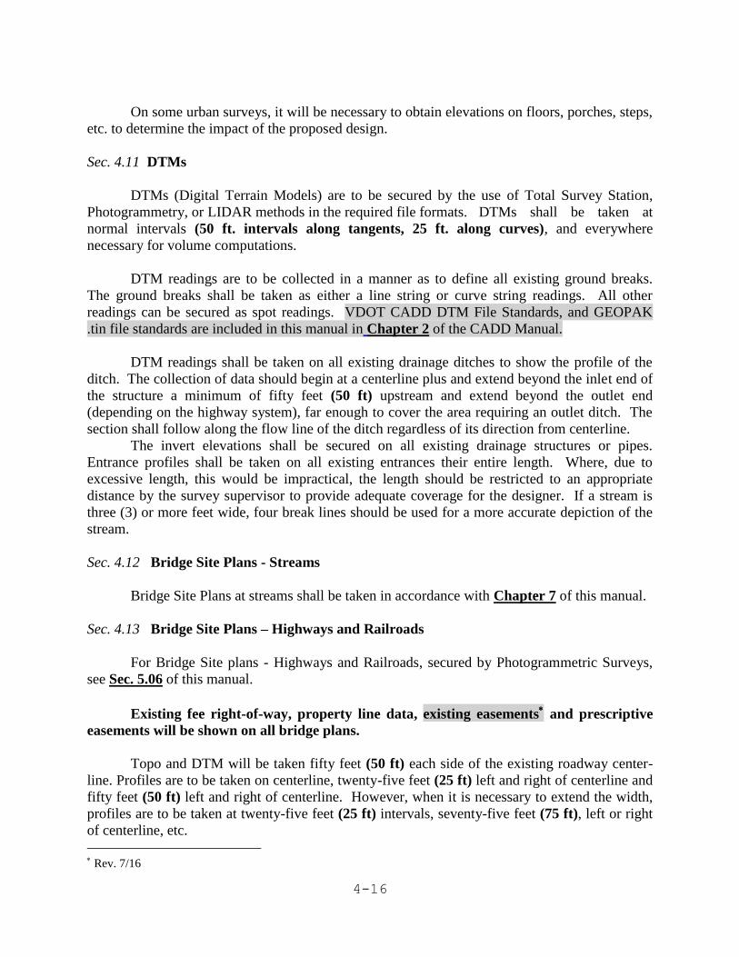
Sec. 4.11 DTMs
DTMs (Digital Terrain Models) are to be secured by the use of Total Survey Station,
Photogrammetry, or LIDAR methods in the required file formats. DTMs shall be taken at
normal intervals (50 ft. intervals along tangents, 25 ft. along curves), and everywhere
necessary for volume computations.
DTM readings are to be collected in a manner as to define all existing ground breaks.
The ground breaks shall be taken as either a line string or curve string readings. All other
readings can be secured as spot readings. VDOT CADD DTM File Standards, and GEOPAK
.tin file standards are included in this manual in Chapter 2 of the CADD Manual.
DTM readings shall be taken on all existing drainage ditches to show the profile of the
ditch. The collection of data should begin at a centerline plus and extend beyond the inlet end of
the structure a minimum of fifty feet (50 ft) upstream and extend beyond the outlet end
(depending on the highway system), far enough to cover the area requiring an outlet ditch. The
section shall follow along the flow line of the ditch regardless of its direction from centerline.
The invert elevations shall be secured on all existing drainage structures or pipes.
Entrance profiles shall be taken on all existing entrances their entire length. Where, due to
excessive length, this would be impractical, the length should be restricted to an appropriate
distance by the survey supervisor to provide adequate coverage for the designer. If a stream is
three (3) or more feet wide, four break lines should be used for a more accurate depiction of the
stream.
Sec. 4.12 Bridge Site Plans - Streams
Bridge Site Plans at streams shall be taken in accordance with Chapter 7 of this manual.
Sec. 4.13 Bridge Site Plans – Highways and Railroads
For Bridge Site plans - Highways and Railroads, secured by Photogrammetric Surveys,
see Sec. 5.06 of this manual.
Existing fee right-of-way, property line data, existing easements and prescriptive
easements will be shown on all bridge plans.
Topo and DTM will be taken fifty feet (50 ft) each side of the existing roadway center-
line. Profiles are to be taken on centerline, twenty-five feet (25 ft) left and right of centerline and
fifty feet (50 ft) left and right of centerline. However, when it is necessary to extend the width,
profiles are to be taken at twenty-five feet (25 ft) intervals, seventy-five feet (75 ft), left or right
of centerline, etc.
Rev. 7/16

4-17
These profiles are to be drawn in a new .dgn file called sUPC#b(bridge #).dgn plotted to
a scale of one inch to ten feet (1” = 10’) both vertically and horizontally. If the area is of
extended width, the profiles may be offset to the right of the situation plan area and plotted in the
usual matter.
Profiles for the road being crossed, railroad being crossed, railroad spurs, entrances, etc.,
are to be plotted to a convenient scale and shown.
Where the site plan is at a railroad crossing, instructions in Sec. 4-5 and Sec. 4-7 of this
manual should be adhered to as they pertain to railroads. The weight of the rail should be shown
prominently on the site plan.
Elevation ticks shall be taken at twenty-five feet (25 ft) intervals from the centerline or
baseline of the road or railroad being crossed 100’ left and right of the crossing.
Sec. 4.14 Bridge Site Plans - Widening
The bridge site plan for widening projects shall be secured and plotted in accordance with
Sec. 4.14 and Chapter 7 of this manual. In the case of widening at streams, no upstream or
downstream cross-sections are to be secured unless specifically requested at a given site, but the
Bridge Data Sheet must be completed.
When an existing bridge is close enough to the location centerline that the proposed
structure might overlay the existing bridge, accurate stations and offsets shall be secured to all
accessible outlines of the existing structure.
Where an existing bridge is to be widened and as-built plans are on file, measurements
shall be secured and shown on a copy of as-built bridge plans as follows:
1. Stations and skew angles at beginning and end of bridge and at all piers.
2. Bridge seat elevations at exterior beams on both sides of the bridge.
3. Dimension from centerline to outside edge of deck.
4. Elevations of basic slab at gutter line at beginning and end of bridge and at
centerline of piers.
This data will be incorporated on the file/disk with all other information.
On certain widening projects, the clearance is often critical, especially if the structure to
be widened crosses a surfaced facility. In view of this, DTMs are to be secured along the
centerline of the roadway beneath the bridge at ten feet (10 ft) intervals. DTMs are to be secured
under the bridge at a distance of ten feet (10 ft) from the centerline of the exterior beam to a dis-
tance ten feet (10 ft) outside the proposed edge of the widened pavement. These DTMs shall
extend to the top of the shoulder or the bottom of the ditch only, except at the regular station or
fifty feet (50 ft) intervals, which are to be collected as usual. Elevations are to be secured for the
bottom of beams at the supports for the exterior beams and any adjacent beams of greater depth.

4-18
For Bridge Site Plans - Widening, secured by Photogrammetric Surveys, see Sec. 5.07 of
this manual.
Sec. 4.15 Minimum Plan Projects
The fundamental objective of a "Minimum Plan" project is to provide a satisfactory basis
for competitive bids without the development of fully detailed plans and cross-sections. In plain
language, such projects will employ varying degrees of the "eyeball" concept of construction
with special provisions in the bid proposal covering such items. The full extent and amount of
survey information to accomplish will need to be determined on a per project basis. The
following are the minimum guidelines:
1. Establish survey alignment and obtain essentially the normal topographic
information such as property lines and property ownership, fences,
utilities, property development and improvements. This topographic
information is essentially the same as normally secured for any project but
on a minimum width unless otherwise recommended or directed by the
Resident Engineer or District L & D Engineer.
1. Obtain centerline profiles but DTMs or cross-sections are not to be
taken unless specifically designated or requested and usually only at
certain specified locations within a proposed project. One of the basic
provisions of a "Minimum Plan" project provides for grading as a
lump sum bid item. Earthwork quantities are not computed and
generally the plans show the centerline profile and perhaps a spline
grade line without specific elevations at each station.
See the current edition of VDOT’s Road Design Manual, Appendix A, Section A-7, titled
“Section A-7 – “No Plan” and “Minimum Plan” Projects”. Excerpts are contained herein as
Figure 8-J.
Sec. 4.16 Additional Survey Data Requests
Ideally, all survey information required should be secured in the initial survey, but from a
practical standpoint, this will not happen. Some items, such as entrance profiles for new private
entrances must be secured after the Field Inspection. Updated memorandum letters will need to
be sent to all affected parcels 15 days prior to entry per Section 4.03.
On projects being designed by the Districts, requests for additional data should be
handled by memorandum within the District. Should the original survey be secured by
Photogrammetric Survey methods and the capability to secure the additional data is available by
this method, the request for this additional data should be forwarded to the Central Office,
attention to the State Photogrammetry Manager.
Rev. 3/14

4-19
The additional data is to be requested by Form LD-261, See Figure 4-B this request is to
be reviewed by the District Survey Manager in the Districts or the State Survey Program
Manager or State Photogrammetry Manager for projects designed by the Central Office.
It is important that the survey and utility master files (complete with survey control,
baselines and topography) and well-marked B/W prints should be attached for topography and
clarity of request. Construction baseline/alignment data should be made available also.
Requests for additional data should be handled on a priority basis according to current
established schedules. Copies of letters transmitting additional data to the Design Units should
be sent to the appropriate individuals per section 1.08.
Sec. 4.17 Submission of Survey Report and Data
Before submitting the survey data, all information should be checked by the Survey Party
Manager. He shall ascertain that the survey embodies all of the required information and that it
is recorded and plotted in accordance with these instructions.
The Survey Party Manager will then write the Survey Report (a copy of which shall be
titled "sUPC#.doc" and shall be included on the server). This document will be placed in Falcon.
The narrative will give a description of the survey and report all features and conditions not fully
covered in the notes that will affect the location, design and construction of the road. Any part of
the survey not conforming to the standards herein specified or generally accepted shall be fully
explained.
It is the responsibility of the District Survey Manager to check each survey for
correctness, completeness and notifying the Project Manager and State Survey Program Manager
that the survey is complete. The District Survey Manager will verify that the survey has been
secured in accordance with the authorization and these instructions and all pertinent information
such as subdivision plans, tract plats and deed book descriptions from court records are included.
Sec. 4.18 Digital Sealing of Microstation and Adobe Files
Beginning July 1st, 2009, all newly submitted survey, utility, and update digital files will
contain a digital signature certifying the Microstation file meets an accepted professional standard
and quality. (IIM-LD-243). This IIM is very specific on what will and will not be sealed by a
licensed professional. All plans submitted for Right of Way approval shall be Sealed and Signed by
a Licensed Land Surveyor. The Microstation digital signature has been provided to VDOT’s
Licensed Surveyors (L.S.). It is the consultant’s responsibility to acquire Falcon access and
digital signatures for submission of files to VDOT upon Notice to Proceed. Survey digital files
whose submission was prior to July 1st, 2009, will not require a digital signature.
Rev. 3/14

4-20
Figure 4-A May 22, 2013
Mr. Property Owner Re: Street Improvements
Ms. Property Owner From: 14th Street NE. To: 0.5 Mi. E. 9th Blvd
222 Broad Street City: Richmond
Richmond, VA 23219 UPC: # 80561
Dear Property Owner:
This letter of intent to enter your property is being sent to you pursuant to Section 33.2-1011 of the Code
of Virginia. The Virginia Department of Transportation (VDOT) is in the early stages of developing the
captioned project and will soon be working in your neighborhood.
Please be advised that VDOT employees or consultants may need to enter your property to perform some
or all of the following investigative tasks: locate property lines and utilities; locate and review physical
features and existing conditions; take photographs; talk to property owners; verify property tax
information, perform environmental resource surveys; investigate potential environmental impacts; and
conduct soil testing and sampling, including, but not limited to shovel tests, soil samples and borings.
Should soil borings or shovel tests be required, every effort will be made to minimize the disturbance to
your property and reduce the time spent on your property. All holes will be backfilled and every effort
will be made to return the surface to the same condition it was before our work began. If borings are
required, approximately 30 days after completion of the borings, the borehole locations will be inspected
for settlement and necessary repairs will be made, if required.
This investigative work does not indicate that improvements across your property are imminent or that a
decision on an improvement has been made. This work is simply for the purpose of gathering data for
the decision making process. Please watch for notices of public meetings or willingness to hold a meeting
about this project. In the event that the transportation improvement does affect your property, a VDOT
representative will personally contact you.
VDOT anticipates that surveyors and engineers will be performing this work intermittently between
approximately September xx, xxxx and December xx, xxxx. Should there be any need to further access
your property after this time, you will be contacted either in person or by mail.
If you have any knowledge of cemeteries, easements, or homeowner installed utilities that are not
recorded in your Locality’s public records or items of interest that may affect the improvements in your
area or have any questions, please contact the undersigned at 804-__-___ or by mail at VDOT
_____District, PO Box ___, ______, VA 23219 or by electronic mail at ________________.
John Smith, P.E. Project Manager

4-21
LD-261 Figure 4-B
http://vdotforms.vdot.virginia.gov/SearchResults.aspx?strFormNumber=LD-261