Embed Size (px)
Citation preview
4-81/4-82
A-C
R-C
CP
-118/PH
-001CHAPTER 4: LESSON SPECIFICATIONS COURSE TITLE: GREEN STAR COURSE CTS NUMBER: A-CR-CCP-116/PC-001
ENABLING OBJECTIVE AND TEACHING POINTS TRAINING DETAILS MAP AND COMPASS: 405.03 5. TIME: Three 30 minutes periods.
1. PERFORMANCE — Locate an object on a map using a four and six figure grid reference.
2. CONDITIONS:
a. Given:
(1) a 1:50 000 map;
(2) pencil and paper; and
b. Denied — assistance.
3. STANDARD — The cadet will accurately locate an object on a map a four and six figure grid reference.
4. TEACHING POINTS:
a. universal transverse Mercator;
b. principles of grid references;
c. grid lines (Northings and Eastings);
d. military grid reference system;
e. four figure grid references;
f. construction of a romer;
g. use of a roomer; and
h. six figure grid references;
6. METHOD/APPROACH:
a. lecture;
b. demonstration; and
c. performance.
7. SUBSTANTIATION — In order to be able to indicate a specific area on a map, the cadet must have a good knowledge of the grid reference system.
8. REFERENCES — a. Cadet Reference Book ( pages 5-14 to 5-19) ; b. B-GL-392-005/FP-001 (chap 6, Arts 601-605); and c. Master Lesson Plan.
9. TRAINING AIDS:
a. 1:50 000 maps; and
b. tables.
10. TEST DETAILS — As per standard statement.
11. REMARKS:
a. Explain clearly to the class that the grid reference system is merely a device for enabling any point to be located on a map. Start by explaining the system on a blackboard and then show how the grid is applied to a map;
b Explain to the class that a six-figure grid reference is used when there are two or more identical features located in one grid square, ie, two crossroads or two bridges; and
c. To confirm the lesson, have the cadets give the four-figure grid references of clearly defined features on their own maps. Using a romer, or by estimation, have them convert these same references to six figures. Course cadets can each be make their
A-CR-CCP-121/PT-001
5-14
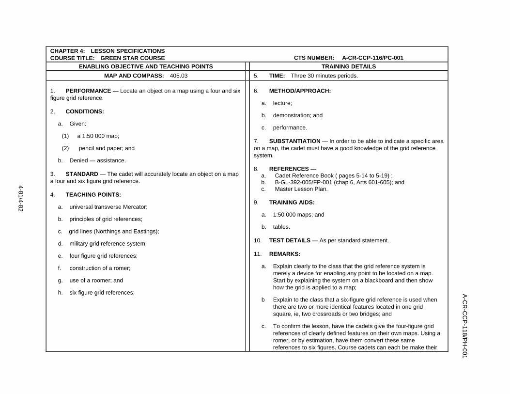
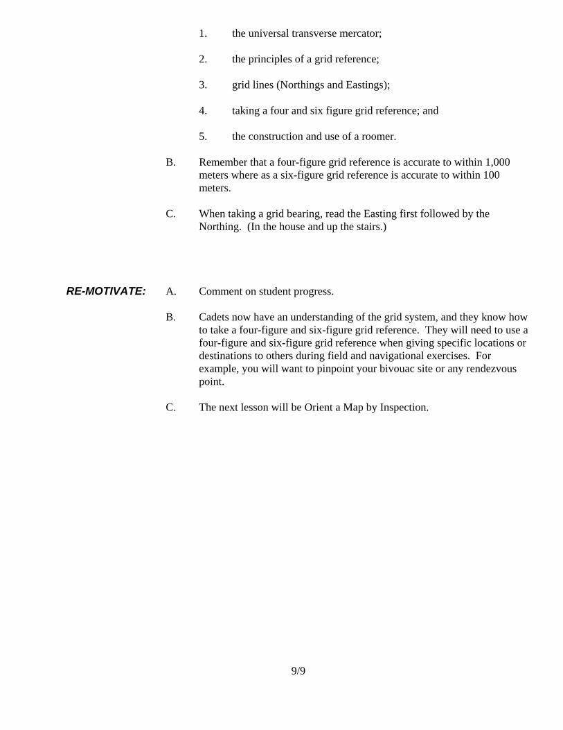
EO 405.03: LOCATE SPECIFIC POINT ON A MAP USING A FOUR AND SIX FIGURE GRID REFERENCE AND CONSTRUCTING A ROMER UNIVERSAL TRANSVERSE MERCATOR GRID Because the world is round, any type of representation of its surface on a flat piece of paper will have distortions. These are relatively insignificant on maps that show only small parts of the earth, like city maps or 1:50 000 scale maps, but quite considerable for maps of countries or continents. A “map projection” is a geometrical method of reducing the amount of distortion on a flat map. In very large countries such as Canada, mapmakers divide the country into strips from north to south, called “zones,” and project each zone. One system of strip projection is the “Universal Transverse Mercator (UTM) Projection.” All National Topographical System (NTS) maps use this system.
Shape of a UTM zone – 6
minutes of longitude wide
To picture a UTM zone, imagine the earth as an orange. All the geographical features are drawn on the peel. Take a knife and, after slicing off small circles at each pole, cut the peel into many narrow strips from pole to pole. Then take the strip of peel and press it flat against a smooth surface. Even though the details in the middle of the peel might become a little distorted, the strip is narrow enough for the details to remain accurate enough for regular map users. For the UTM Projection, the earth’s surface has been divided into 60 zones. Sixteen of these zones, numbered 7 through 22, cover Canada
A-CR-CCP-121/PT-001
5-15
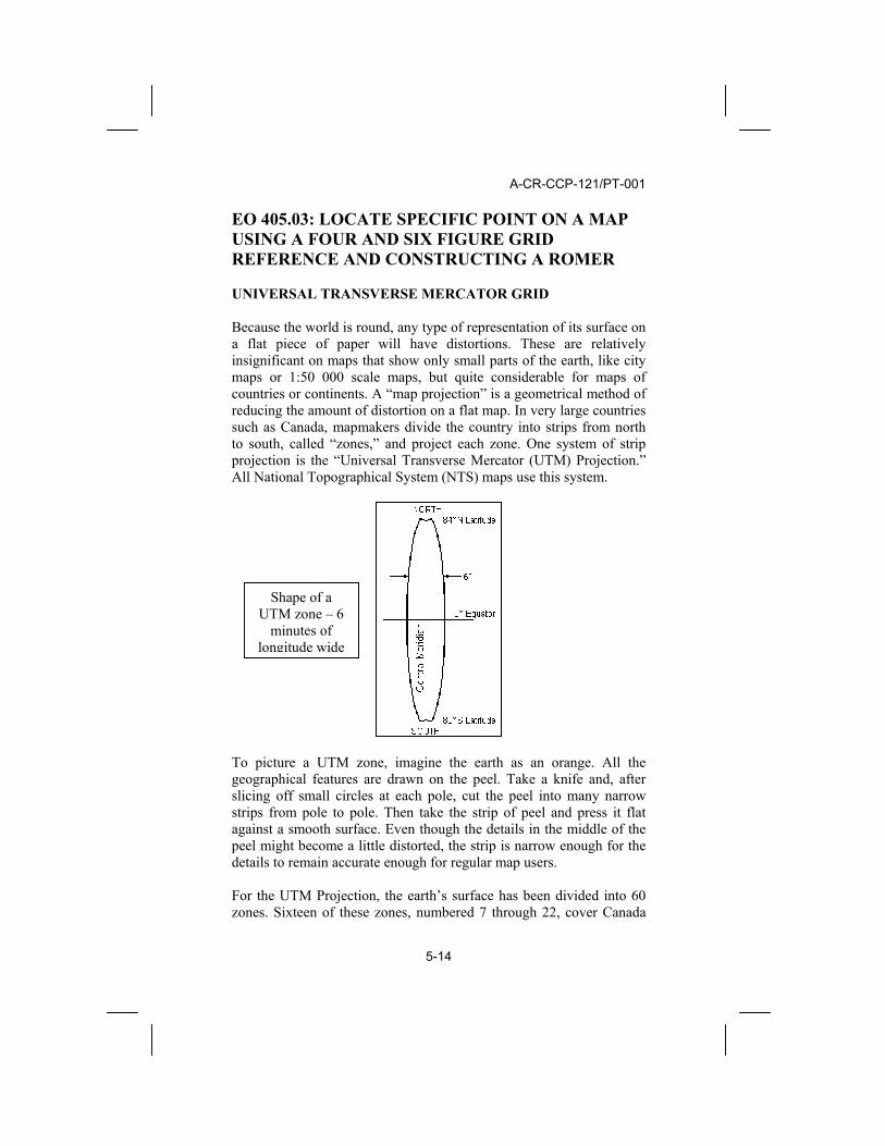
from west to east. Shown below are the numbered zones with their centre meridian marked with a dotted line
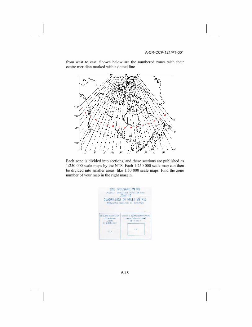
Each zone is divided into sections, and these sections are published as 1:250 000 scale maps by the NTS. Each 1:250 000 scale map can then be divided into smaller areas, like 1:50 000 scale maps. Find the zone number of your map in the right margin.

A-CR-CCP-121/PT-001
5-16
GRID REFERENCE SYSTEMS When a mapmaker has projected a zone, and divided it into sections, a rectangular grid is laid over top of the projection. These grid lines are shown in blue on a topo map. The grid lines are exactly parallel to each other. The vertical grid lines are printed parallel to the meridian of the zone, and the horizontal grid lines are parallel to the equator. The largest of the grids are squares that are 100km x 100km. Each of these 100km squares is identified by a letter which is stated after the UTM zone number. In the example above, the Grid Zone Designation is “10 U.” Each large square is further divided into smaller squares of 10km, and then again into 1km squares. It is these 1km x 1km (1000m x 1000m) squares that you see on a 1:50 000 scale topo map. EASTINGS Each grid line in the 1000m grid is numbered. The vertical lines are numbered from an imaginary line 500 000 metres west of the zone’s centre meridian. Each zone then starts at zero in the west and each 1000m line is numbered going towards the east. In the bottom and top margins you will find each vertical grid line’s number, usually a two-digit number at the top and bottom ends of the line. In the bottom left corner you can see the full number represented with the letter E printed behind it. This tells you how many metres east of the start point you are. Because these lines are numbered from west towards the east, they’re called “Eastings.” NORTHINGS Each horizontal line is also numbered, this time starting with zero at the equator. In the left and right margin you will find the two-digit numbers at the ends of each horizontal line. In the bottom left you will find the full number of metres from the equator with the letter N printed behind it. Note that the most southerly part of Canada 4 620 000 metres from the equator. Because these lines are numbered from the equator towards the north, they are called “Northings.”
A-CR-CCP-121/PT-001
5-17
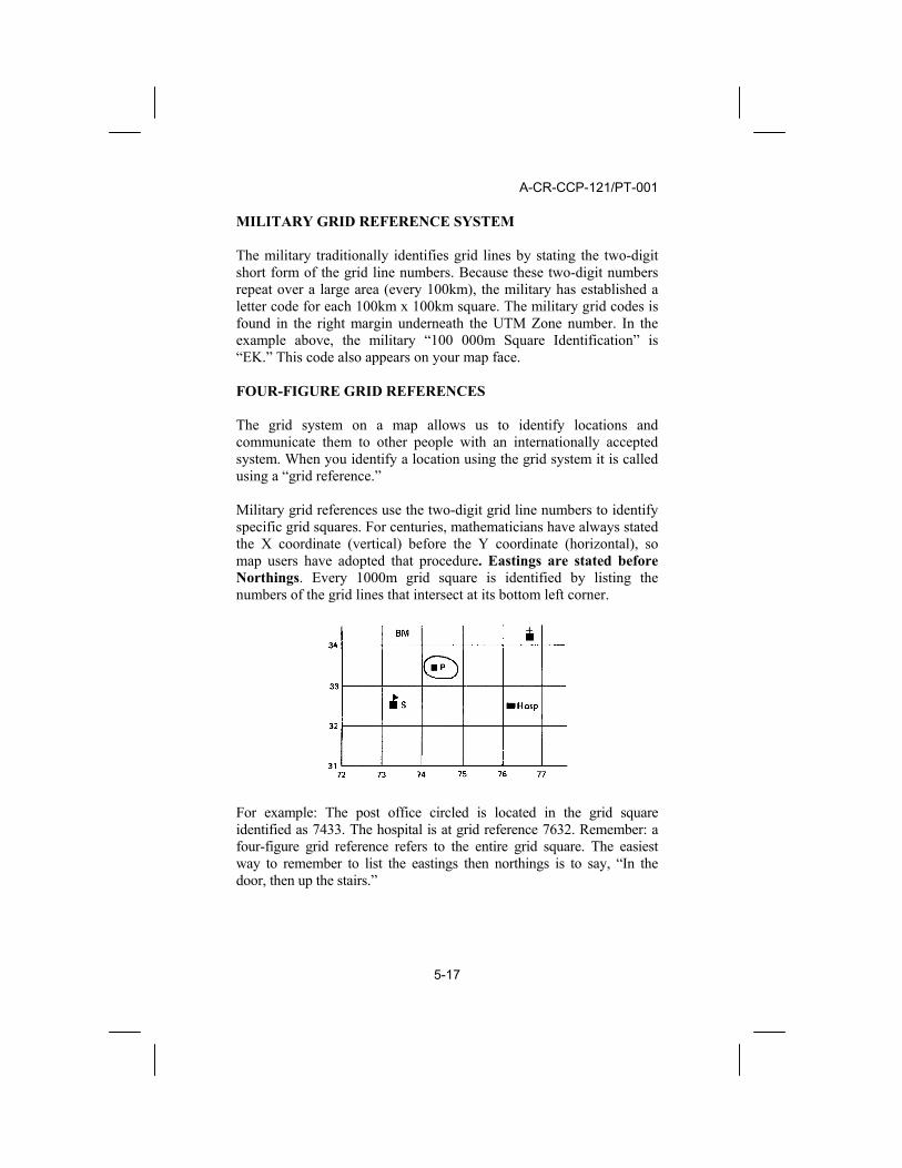
MILITARY GRID REFERENCE SYSTEM The military traditionally identifies grid lines by stating the two-digit short form of the grid line numbers. Because these two-digit numbers repeat over a large area (every 100km), the military has established a letter code for each 100km x 100km square. The military grid codes is found in the right margin underneath the UTM Zone number. In the example above, the military “100 000m Square Identification” is “EK.” This code also appears on your map face. FOUR-FIGURE GRID REFERENCES The grid system on a map allows us to identify locations and communicate them to other people with an internationally accepted system. When you identify a location using the grid system it is called using a “grid reference.” Military grid references use the two-digit grid line numbers to identify specific grid squares. For centuries, mathematicians have always stated the X coordinate (vertical) before the Y coordinate (horizontal), so map users have adopted that procedure. Eastings are stated before Northings. Every 1000m grid square is identified by listing the numbers of the grid lines that intersect at its bottom left corner.
For example: The post office circled is located in the grid square identified as 7433. The hospital is at grid reference 7632. Remember: a four-figure grid reference refers to the entire grid square. The easiest way to remember to list the eastings then northings is to say, “In the door, then up the stairs.”

A-CR-CCP-121/PT-001
5-18
SIX-FIGURE GRID REFERENCES In wilderness navigation we often need to be more accurate with a grid reference for a location than a 1000m x 1000m square. In the illustration below you’ll notice that the grid square has more than one bridge, so communicating which bridge you are going to meet at would be impossible using a four-figure grid reference.
By creating an imaginary grid inside a grid square, we can use the same principles of the grid reference to make a more accurate statement of location. Each small easting and northing is numbered 1 to 9, from west to east and from south to north respectively. Then each smaller (100m x 100m) square can be identified listing all eastings, then northings. For example: Grid reference 761326 is given, the easting is 761 or 76 and 1/10, and the northing is 326 or 32 and 6/10. Locate your grid square at 7632 and then go in 1 and up 6. .
a. There is a church at grid reference 764324; and b. There is a T-junction in the road at 768327
Remember that a six-figure grid reference describes a square 100m x 100m. This imaginary grid inside a square can be estimated, or you can measure accurately using a tool called a “romer.”

A-CR-CCP-121/PT-001
5-19
CONSTRUCTION AND USE OF A ROMER A romer is a device used for measuring a point within a grid square rather than estimating. The left side of the metres scale bar is divided into100m segments. Use a blank corner of a piece of paper, place it along the scale, mark off the 100m segments and then number them, starting with zero at the point. Number both sides up to 10.
To use, place the corner of your romer on the grid square and move in the number of tenths and up the number of tenths. The grid reference for the building in the example below is 766327. Note: always round down.

ROYAL CANADIAN ARMY CADETS
Star Program
Master Lesson Plan
2006-05-04 1/9
GREEN STAR COURSE PO: MAP AND COMPASS ENABLING OBJECTIVE(S): 405.03: Locate an Object on a Map Using a Four-Figure and Six- Figure Grid Reference REFERENCE(S): A. A-CR-CCP-118/PH-001 Green Star Course Training Plan; Chapter 4, Page 4-81/4-82. B. A-CR-CCP-121/PT-001 Cadet Reference Book, Pages 5-14 – 5-19. C. A-CR-CCP-108 Basic Map Using Program Package; Chapter 1, Arts
12-19. D. A-CR-CCP-111 Visual Aids, Page 21. SUPPLEMENTARY REFERENCE(S): A. B-GL-382-005/FP-001 Map, Field Sketching and
Compass; Chapter 6, Section 1, Arts 601-605. B. http://maps.nrcan.gc.ca TRG AID(S): A. OHP B. OHP Slides C. Topographical maps (1 per 2 cadets) D. Tables STUDENT AID(S): A. Green Star Handbook B. Pencil and notebook METHOD: Lecture, Demonstration and Performance TIME: 3 x 30 Minutes
REVIEW TIME: 5 Minutes I EO 405.02: STATE THE MEANING OF CONVENTIONAL SIGNS FOUND ON A
TOPOGRAPHICAL MAP 1. What information can be found in the margin of a map?
Answer: Refer to A-CR-CCP-118 Green Star Handbook . 2. Which of the following is marginal information? Conventional signs?
a. Map scale bars Answer: Marginal information b. House Answer: Conventional sign

2/9
c. Magnetic declination Answer: Marginal information d. Telephone line Answer: Conventional sign
3. What are conventional signs?
Answer: Symbols used to portray various objects or features on the ground.
INTRODUCTION TIME: 1 Minute WHAT: During this period of instruction cadets will learn how to locate an object on a map using
a four-figure and six-figure grid reference. WHY: As an army cadet it is important to know how to use the grid system. Since the grid
system is the basis of map reading, the concept of a four-figure and six-figure grid reference will be a building block for becoming a strong map-reader. A grid reference details the exact location of a grid square on a map and prevents confusion about location. Communication about exact locations over the radio is made possible with the concept of a grid reference.
WHERE: Cadets will use the grid system on field and navigational exercises at the local unit and at
summer training centers.
BODY INSTR NOTES I STAGE 1: UNIVERSAL TRANSVERSE MERCATOR GRID
1. UTM: The Universal Transverse Mercator (UTM) is a system of
strip projections used by mapmakers to produce an accurate map. Because the world is round, any type of representation of its surface on a flat piece of paper will have distortions. A “map projection” is a geometrical method of reducing the amount of distortion on a flat map. All National Topographical System maps use the UTM system. For the UTM Projection: a. The earth’s surface has been divided into 60 strips from
north to south, called “zones” and projects each zone; b. Each zone is six minutes of longitude wide; c. Sixteen of these zones, numbered 7 through 22, cover
Canada from west to east; d. Each zone is divided into sections, and these section are
published as 1:250 000 scale maps by the NTS; and e. Each 1:250 000 scale map can then be divided into smaller
TIME: 15 Minutes OHP 1 Use an orange to illustrate. Take a knife and, after slicing off small circles at each pole, cut the peel into many narrow strips from pole to pole. Then take the strip of peel and press it flat against a smooth surface. Even though the details in the middle of the peel might become a little distorted the strip is narrow enough for the details to remain accurate enough for regular map users.

3/9
areas, like 1:50 000 scale maps. 2. Grid Reference System: When a mapmaker has projected a
zone, and divided it into sections, a rectangular grid is laid over top of the projection. These grid lines are shown in blue on a topographic map. The grid lines are exactly parallel to each other. The vertical grid lines are printed parallel to the meridian of the zone, and the horizontal grid lines are parallel to the equator. a. Each grid zone covers six degrees of longitude and eight
degrees of latitude (except for the most northerly band from 72°N to 84°N, which covers 12° of latitude).
b. Each of these grid zones is identified by a Number for the
60 bands of longitude and a Letter for the 20 bands of latitude. Thus, “14U”;
c. Each grid zone is subdivided into the largest of the grids
squares that are 100km x 100km; d. Each large square is further divided into smaller squares of
10km, and then again into 1km squares; and e. these 1km x 1km (1000m x 1000m) squares are those seen
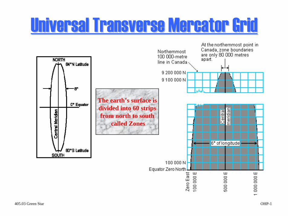
on a topographic map. 3. Eastings: Each grid line in the 1000m grids is numbered. The
vertical lines are numbered from an imaginary line 500 000 metres west of the zone’s centre meridian. Each zone then starts at zero in the west and each 1000m line is numbered going towards the east. In the bottom and top margins you will find each vertical grid line’s number, usually a two-digit number. In the bottom left corner you can see the full number represented with the letter E printed behind it. This tells you how many metres east of the start point you are. These vertical lines numbered from west towards the east, are called “Eastings.”
4. Northings: Each horizontal line is also numbered, this time
starting with zero at the equator. In the left and right margin you will find the two-digit numbers at the ends of each horizontal line. In the bottom left you will find the full number of metres from the equator with the letter N printed behind it. Note that the most southerly part of Canada 4 620 000 metres from the equator. These horizontal lines numbered from the equator towards the north, are called “Northings.”
5. Military Grid Reference System: The military traditionally
identifies grid lines by stating the two-digit short form of the grid line numbers. Because these two-digit numbers repeat over a large
OHP 2 OHP 3 Refer to OHP 2

4/9
area (every 100km), the military has established a letter code for each 100km x 100km square. The military grid codes are found in the right margin underneath the UTM Zone number. i.e. “100 000m Square Identification” is “ML.”
II CONFIRMATION STAGE 1
1. What is UTM? 2. How many UTM zones cover Canada? 3. What are Eastings? Northings? 4. How is the military grid reference system identified?
III STAGE 2: FOUR-FIGURE GRID REFERENCES
1. Grid System: The grid system on a map allows us to identify
locations and communicate them to other people with an internationally accepted system. Grid squares are formed where the Northings and Eastings cross each other.
2. Grid Reference: A grid reference is a method used to accurately
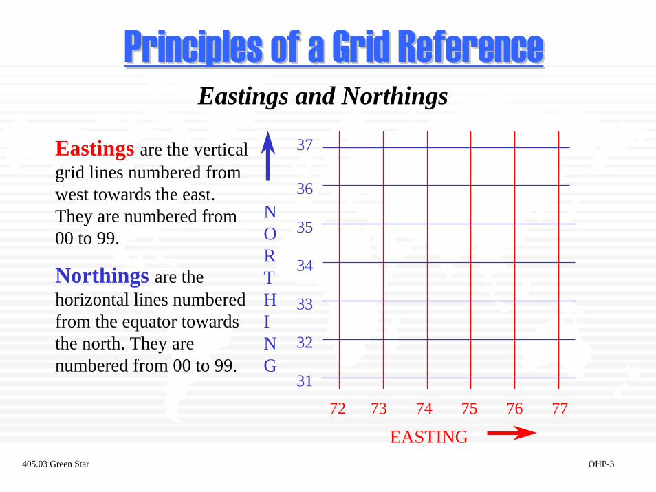
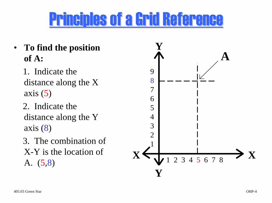
indicate a specific point on a map sheet. Military grid references use the two-digit grid line numbers to identify specific grid squares. For centuries, mathematicians have always stated the X coordinate (vertical) before the Y coordinate (horizontal), so map users have adopted that procedure. Eastings are stated before Northings. Every 1000m grid square is identified by listing the numbers of the grid lines that intersect at its bottom left corner. The position of any object can be determined by measuring its distance from an X-Y axis. a. The position of “A” can be given by indicating its distance
to the right of line Y-Y (5) and above line X-X (8). b. The X,Y combination of (5,8) gives the position of “A”.
3. Accuracy: There are three different kinds of grid references:
four, six, and eight-figure. Grid references are always given in even numbers of digits. The type used is determined by how much accuracy you require. a. Four-figure: refers to 1,000 m2; accurate to within
1,000m. b. Six-Figure: refers to 100 m2; accurate to within 100m.
TIME: 20 Minutes OHP 4 Note: 6-figure grid references will be covered in the next
5/9
c. Eight-figure: refers to 10 m2; accurate to within 10m.
4. Order of a grid reference: When taking a grid reference, follow
this procedure:
a. The distance to the east, or the Easting, is always the first half of the GR. The grid line defines the west side of the grid square.
b. The distance to the north, or the Northing, is always the
second half of the GR. The grid line defines the south side of the grid square.
EXAMPLE: GR 3064: 30 is the Easting, 64 is the
Northing
Note: Refer to OHP 5: Indicate the easting and northing, point out how the lines form the west and south sides of the square. Remind the cadets of how the grid lines are numbered (00 to 99).
5. What is a four-figure grid reference used for? A four-figure
grid reference is used to identify main features located in a grid square. (Ex: a village, a lake, a road intersection)
Note: A four-figure grid reference is normally used only when one feature of its kind is located in the grid square. For example, you could not use a four-figure GR to locate a church if there were two churches in the grid square.
6. OHP 5: Use this slide to locate what conventional sign is found
at each grid reference: a. GR 31 65 Answer: Church b. GR 29 64 Answer: Cemetery
IV CONFIRMATION STAGE 2
1. What is the accuracy of a four-figure grid reference? 2. Which is read first, the northing or the easting? 3. What is a simple way to remember the order of taking a grid
reference? 4. When would a four-figure grid reference be used?
Stage. Cadets seldom use an 8-fig. grid reference, but it can be mentioned. Note: An easy way to remember this concept is “in the house and up the stairs”. OHP 5 OHP 5
6/9
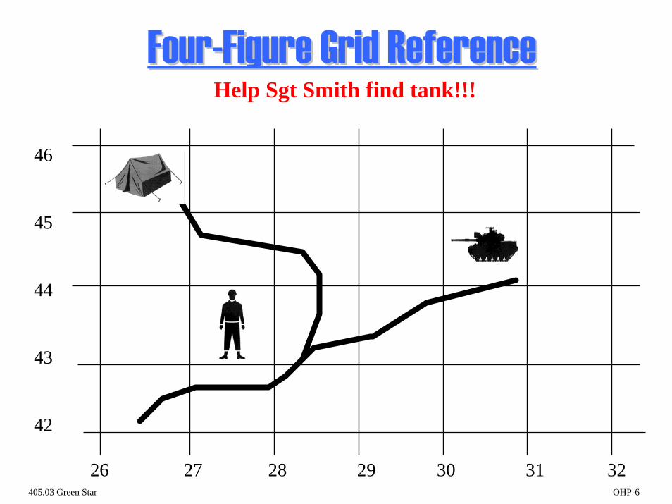
5. OHP 6: Help Sgt Smith locate his tank.
a. Where is Sgt Smith? Answer: GR 2743
b. Where is the tent? Answer: GR 2645
c. Where is Sgt Smith’s tank? Answer: GR 3044 V STAGE 3: SIX FIGURE GRID REFERENCE
1. What is a six-figure grid reference? A six-figure grid reference
is a way of pinpointing a location or feature within a grid square. (Remember that a four-figure GR only locates the square.)
2. When is a six-figure grid reference used? We use a six-figure
GR when: a. there are two or more features located in the same grid
square (ie: two bridges) and we need to be specific; and b. when we need to be exact when giving the location of
something (ie: a bivouac site, the start point for a hike). 3. Concept of a six-figure grid reference: You will recall that a
four-figure grid reference refers to a single grid square. A six-figure grid reference refers to the same square, but it divides it into 100 smaller squares. A six-figure grid reference indicates which small square the feature is in.
EXAMPLE: Refer to OHP 8: Grid square 7632 contains 5 bridges. How can you be sure which bridge to go to if it is not indicated somehow? a. Division of a Grid Square: Imaginary lines divide the
square into 10ths. It is easy to imagine these lines even if they are not on your map.
b. Line numbering: The numbering of the lines indicate how
many 10ths east and north of the grid lines the feature in question is (in this example, the bridges).
4. Order of taking a six-figure grid reference: You take a six-
figure grid reference in almost the same manner as a four-figure GR:
OHP 6 TIME: 20 Minutes OHP 7 OHP 8 Point out the lines on OHP 8 and show how they are numbered consecutively from 1 to 9.

7/9
a. As stated, when taking a six-figure GR, you are referring to the imaginary smaller square within the original grid square. (i) To get to the small square, note how many 10ths
the feature is east of the main grid line (Easting 76 in the example).
(ii) Note how many 10ths the feature is north of the
main grid line (Northing 32 in the example). b. Remember “in the house, and up the stairs” when
determining your 6-figure GR:
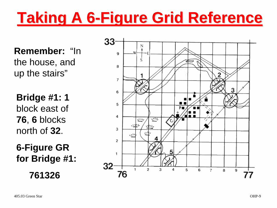
EXAMPLE: Refer to OHP 9:
Bridge #1: This bridge is 1/10 of the way past grid line 76, and 6/10s of the way above grid line 32. The 6-figure GR for this bridge is 761326.
c. Note: As with a 4-figure GR, the grid line 761 defines the
west side of the small square, and grid line 326 defines the south side.
VI CONFIRMATION STAGE 3
1. Why is there a need for six-figure grid references? 2. Using OHP 9, have the cadets find the six-figure grid references
for the remaining 4 bridges. a. Bridge 2: GR 767326 b. Bridge 3: GR 768325 c. Bridge 4: GR 762321 d. Bridge 5: GR 763320
VII STAGE 4: CONSTRUCTION OF A ROMER
1. The Romer: Up to this point you have been estimating how far
the object is to the right of and above the grid lines. In most cases, this method is not quite accurate enough. You will need a device called a romer to measure the grid reference.
2. Construction of a romer: A romer can easily be made on the
corner of a piece of paper. a. Look at the scale bars on the bottom of your map. You
OHP 9 TIME: 8 Minutes Demonstrate to the class.
8/9
will use the meters bar. Note how the left end of the bar is divided into 10ths. This divided scale bar is the exact same size as a grid square.
b. Take a blank piece of paper and place the upper right
corner along the divided scale bar. Carefully mark off the 10ths on both edges of the paper. You can number the divisions if your pencil is very sharp.
3. Use of a romer: You can now accurately measure your 6-figure
grid reference: a. Place the corner of your romer on the landmark. b. Read off the 10ths. If the landmark is not exactly on a
line, go to the nearest 10th mark.
EXAMPLE: Refer to OHP 10 VIII CONFIRMATION STAGE 4
1. What is a romer? 2. What is a romer used for? 3. Have the cadets construct a romer using the meters scale bar on
their map.
OHP 10
PERFORMANCE CHECK TIME: 20 Minutes I Using a topographical map, each cadet must locate the correct grid square using a four-figure and six-figure grid reference.
1. Give the cadets several four-figure grid references to locate on a map sheet. (Prepare
your GRs ahead of time.) Have the cadets identify the predominant feature in the square. 2. Prepare a series of six-figure grid references that locate different features (ie:
conventional signs) on the map. Cadets can use the roomers constructed in Stage 4. 3. You can also select a particular grid square and have the cadets determine the 6-figure
GR for certain features in the square.
CONCLUSION TIME: 1 Minute SUMMARY: A. During this period of instruction you have learned:
9/9
1. the universal transverse mercator; 2. the principles of a grid reference; 3. grid lines (Northings and Eastings); 4. taking a four and six figure grid reference; and 5. the construction and use of a roomer.
B. Remember that a four-figure grid reference is accurate to within 1,000
meters where as a six-figure grid reference is accurate to within 100 meters.
C. When taking a grid bearing, read the Easting first followed by the
Northing. (In the house and up the stairs.) RE-MOTIVATE: A. Comment on student progress.
B. Cadets now have an understanding of the grid system, and they know how
to take a four-figure and six-figure grid reference. They will need to use a four-figure and six-figure grid reference when giving specific locations or destinations to others during field and navigational exercises. For example, you will want to pinpoint your bivouac site or any rendezvous point.
C. The next lesson will be Orient a Map by Inspection.
Universal TransverseUniversal Transverse MercatorMercator GridGrid
The earth’s surface isdivided into 60 strips from north to south
called Zones
405.03 Green Star OHP-1

Grid Reference SystemGrid Reference SystemEach grid zone covers 6° of longitude and 8° of latitude.Each grid zone is identified by a number for the 60 band of longitude and a letter for the 20 bands of latitude.Each Grid Zone is subdivided into grid squares 100Km x 100Km and again and again to 1Km x 1Km squares found on atopo map.
405.03 Green Star OHP-2
Principles of a Grid ReferencePrinciples of a Grid ReferenceEastings and Northings
EASTING
N O R T H I N G
37
36
35
34
33
32
31
72 73 74 75 76 77
Eastings are the vertical grid lines numbered from west towards the east. They are numbered from 00 to 99.
Northings are the horizontal lines numbered from the equator towards the north. They are numbered from 00 to 99.
405.03 Green Star OHP-3
Principles of a Grid ReferencePrinciples of a Grid ReferenceY
Y
X X1 2 3 4 5 6 7 8
987654321
A• To find the position
of A:1. Indicate the distance along the X axis (5)2. Indicate the distance along the Y axis (8)3. The combination of X-Y is the location of A. (5,8)
405.03 Green Star OHP-4

Order of Working a Grid Reference1. The Easting is always the first half of the Grid Reference. This line forms the west side of the grid square.
2. The Northing is thesecond half of the GR. This line forms thesouth side of the grid square.
REMEMBER: In the house and up the stairs!!
405.03 Green Star OHP-5
FourFour--Figure Grid ReferenceFigure Grid ReferenceHelp Sgt Smith find tank!!!
46
45
44
43
42
26 27 28 29 30 31 32405.03 Green Star OHP-6

The SixThe Six--Figure Grid ReferenceFigure Grid Reference• A 6-figure grid reference is a way
of pinpointing a feature within a grid square.
• It is accurate to within 100 metersand deals with 100m2 of ground.
• A 6-figure GR is used when:1. there are 2 or more of the same feature in a grid square, and
2. we need to be exact in giving a location.
405.03 Green Star OHP-7

The SixThe Six--Figure Grid ReferenceFigure Grid ReferenceA 6-figure grid reference divides a grid square into 100 small squares.
Grid Square 7632contains 5 bridges.
How will you know which one to go to?
405.03 Green Star OHP-8
Taking A 6Taking A 6--Figure Grid ReferenceFigure Grid Reference
Remember: “In the house, and up the stairs”
Bridge #1: 1 block east of 76, 6 blocks north of 32.
6-Figure GR for Bridge #1:
761326
405.03 Green Star OHP-9
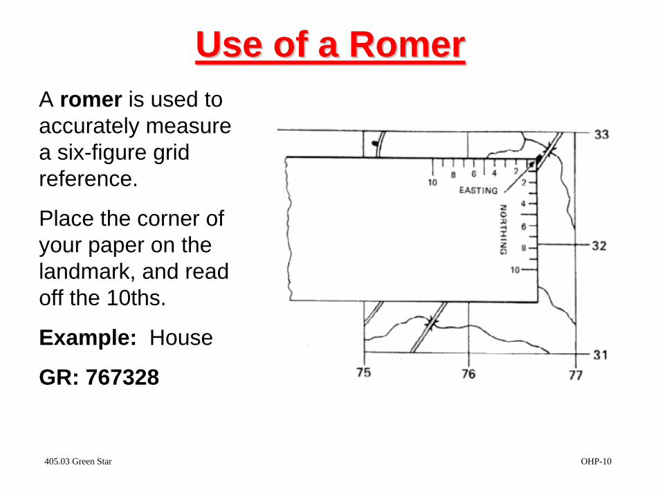
Use of aUse of a RomerRomerA romer is used to accurately measure a six-figure grid reference.
Place the corner of your paper on the landmark, and read off the 10ths.
Example: House
GR: 767328
405.03 Green Star OHP-10

ROYAL CANADIAN ARMY CADETS
Lesson Activity
2006-05-05 1/2
405.03 FOUR AND SIX FIGURE GRID REFERENCES
Aim: 1. The aim of this activity is to assist the cadet in locating objects with four and six figure grid references. Skills Practiced: 2. Cadets will be required to apply the following skills: a. locate objects using four figure grid references; and, b. locate objects using six figure grid references. Location: 3. This activity should be conducted in the classroom but may be used as a game for the purpose of review. Description: 4. This activity is designed to give the cadets a better understanding of using a map to locate objects. It is done by using a large scale representation of a map. Equipment Required: 5. The following equipment is required: a. Large scale map sheet b. place cards to represent conventional signs. Set-up: 6. The instructor shall have the following items prepared prior to the implementation of this activity:
a. conventional sign place cards prepared to be read or placed on the map sheet; and,
b. grid references to teach and confirm proper identification of conventional sign place cards.

2/2
Activity: 7. The instructor may use this activity to demonstrate the correct procedure for locating object using four or six figure grid references by showing the cadets how to travel along the Eastings first, and then the Northings. The instructor can place the conventional sign cards within a grid square on the map sheet and then walk the cadets (in 3-dimension) how to locate it on the map. 8. The following steps should be used to implement the activity as a confirmation;
a. each cadet will receive a card with a four or six figure grid reference and an object to be placed at that location;
b. the cadet will then advance to the map sheet and correctly place his/her object; and,
c. the instructor will either praise or correct the cadet as required. Summary: 9. For variations of this activity, the objects could be pre-placed and the cadets asked to record the grid references or a combination of identifying and placing objects could be used.