Embed Size (px)
Citation preview
CHAPTER 4
FOUNDATIONS
SECTION R401GENERAL
R401.1 Application. The provisions of this chapter shall con-trol the design and construction of the foundation and founda-tion spaces for all buildings. In addition to the provisions of thischapter, the design and construction of foundations in areasprone to flooding as established by Table R301.2(1) shall meetthe provisions of Section R324. Wood foundations shall bedesigned and installed in accordance with AF&PA Report No.7.
Exception: The provisions of this chapter shall be permit-ted to be used for wood foundations only in the followingsituations:
1. In buildings that have no more than two floors and aroof.
2. When interior basement and foundation walls areconstructed at intervals not exceeding 50 feet (15 240mm).
Wood foundations in Seismic Design Category D0, D1 or D2
shall be designed in accordance with accepted engineeringpractice.
R401.2 Requirements. Foundation construction shall becapable of accommodating all loads according to Section R301and of transmitting the resulting loads to the supporting soil.Fill soils that support footings and foundations shall bedesigned, installed and tested in accordance with acceptedengineering practice. Gravel fill used as footings for wood andprecast concrete foundations shall comply with Section R403.
R401.3 Drainage. Surface drainage shall be diverted to astorm sewer conveyance or other approved point of collectionso as to not create a hazard. Lots shall be graded to drain surfacewater away from foundation walls. The grade shall fall a mini-mum of 6 inches (152 mm) within the first 10 feet (3048 mm).
Exception: Where lot lines, walls, slopes or other physicalbarriers prohibit 6 inches (152 mm) of fall within 10 feet(3048 mm), the final grade shall slope away from the foun-dation at a minimum slope of 5 percent and the water shallbe directed to drains or swales to ensure drainage away fromthe structure. Swales shall be sloped a minimum of 2 percentwhen located within 10 feet (3048 mm) of the buildingfoundation. Impervious surfaces within 10 feet (3048 mm)of the building foundation shall be sloped a minimum of 2percent away from the building.
R401.4 Soil tests. Where quantifiable data created by soundsoil science methodologies indicate expansive, compressible,shifting or unknown soil characteristics are likely to be present,the building official shall determine whether to require a soiltest to determine the soil’s characteristics at a particular loca-tion. This test shall be made by an approved agency using anapproved method.
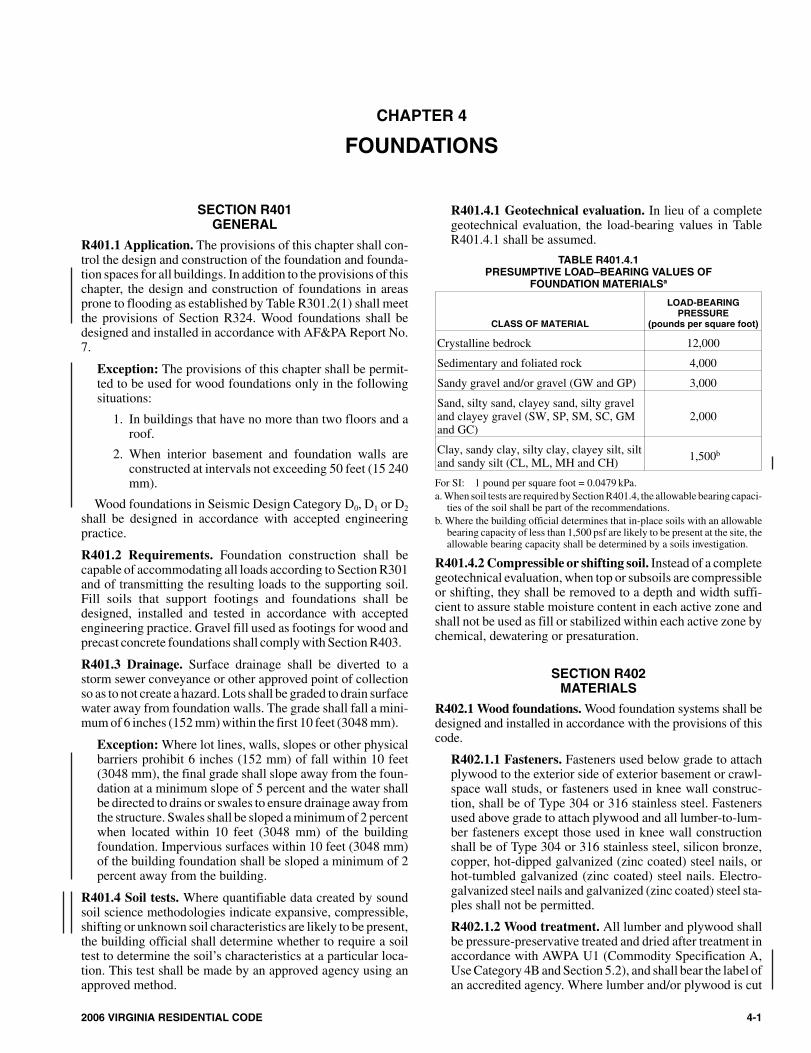
R401.4.1 Geotechnical evaluation. In lieu of a completegeotechnical evaluation, the load-bearing values in TableR401.4.1 shall be assumed.
TABLE R401.4.1PRESUMPTIVE LOAD–BEARING VALUES OF
FOUNDATION MATERIALSa
CLASS OF MATERIAL
LOAD-BEARINGPRESSURE
(pounds per square foot)
Crystalline bedrock 12,000
Sedimentary and foliated rock 4,000
Sandy gravel and/or gravel (GW and GP) 3,000
Sand, silty sand, clayey sand, silty graveland clayey gravel (SW, SP, SM, SC, GMand GC)
2,000
Clay, sandy clay, silty clay, clayey silt, siltand sandy silt (CL, ML, MH and CH) 1,500b
For SI: 1 pound per square foot = 0.0479 kPa.a. When soil tests are required by Section R401.4, the allowable bearing capaci-
ties of the soil shall be part of the recommendations.b. Where the building official determines that in-place soils with an allowable
bearing capacity of less than 1,500 psf are likely to be present at the site, theallowable bearing capacity shall be determined by a soils investigation.
R401.4.2 Compressible or shifting soil. Instead of a completegeotechnical evaluation, when top or subsoils are compressibleor shifting, they shall be removed to a depth and width suffi-cient to assure stable moisture content in each active zone andshall not be used as fill or stabilized within each active zone bychemical, dewatering or presaturation.
SECTION R402MATERIALS
R402.1 Wood foundations. Wood foundation systems shall bedesigned and installed in accordance with the provisions of thiscode.
R402.1.1 Fasteners. Fasteners used below grade to attachplywood to the exterior side of exterior basement or crawl-space wall studs, or fasteners used in knee wall construc-tion, shall be of Type 304 or 316 stainless steel. Fastenersused above grade to attach plywood and all lumber-to-lum-ber fasteners except those used in knee wall constructionshall be of Type 304 or 316 stainless steel, silicon bronze,copper, hot-dipped galvanized (zinc coated) steel nails, orhot-tumbled galvanized (zinc coated) steel nails. Electro-galvanized steel nails and galvanized (zinc coated) steel sta-ples shall not be permitted.
R402.1.2 Wood treatment. All lumber and plywood shallbe pressure-preservative treated and dried after treatment inaccordance with AWPA U1 (Commodity Specification A,Use Category 4B and Section 5.2), and shall bear the label ofan accredited agency. Where lumber and/or plywood is cut
2006 VIRGINIA RESIDENTIAL CODE 4-1
104_Va_Res_2006.psM:\data\CODES\STATE CODES\Virginia\2006\Residential Code\Final VP\04_Va_Res_2006.vpThursday, April 10, 2008 11:08:00 AM
Color profile: Generic CMYK printer profileComposite Default screen
or drilled after treatment, the treated surface shall be fieldtreated with copper naphthenate, the concentration of whichshall contain a minimum of 2 percent copper metal, byrepeated brushing, dipping or soaking until the woodabsorbs no more preservative.
R402.2 Concrete. Concrete shall have a minimum specifiedcompressive strength of ′fc , as shown in Table R402.2. Con-crete subject to moderate or severe weathering as indicated inTable R301.2(1) shall be air entrained as specified in TableR402.2. The maximum weight of fly ash, other pozzolans, sil-ica fume, slag or blended cements that is included in concretemixtures for garage floor slabs and for exterior porches, carportslabs and steps that will be exposed to deicing chemicals shallnot exceed the percentages of the total weight of cementitiousmaterials specified in Section 4.2.3 of ACI 318. Materials usedto produce concrete and testing thereof shall comply with theapplicable standards listed in Chapter 3 of ACI 318.
R402.3 Precast concrete. Approved precast concrete founda-tions shall be designed and installed in accordance with theprovisions of this code and the manufacturer’s installationinstructions.
SECTION R403FOOTINGS
R403.1 General. All exterior walls shall be supported on con-tinuous solid or fully grouted masonry or concrete footings,wood foundations, or other approved structural systems whichshall be of sufficient design to accommodate all loads accord-ing to Section R301 and to transmit the resulting loads to thesoil within the limitations as determined from the character ofthe soil. Footings shall be supported on undisturbed naturalsoils or engineered fill.
Exception: One-story detached accessory structures usedas tool and storage sheds, playhouses and similar uses, not
exceeding 256 square feet (23 7824 m2) of building area,provided all of the following conditions are met:
1. The building eave height is 10 feet or less.
2. The maximum height from the finished floor level tograde does not exceed 18 inches.
3. The supporting structural elements in direct contact withthe ground shall be placed level on firm soil and whensuch elements are wood they shall be approved pressurepreservative treated suitable for ground contact use.
4. The structure is anchored to withstand wind loads asrequired by this code.
5. The structure shall be of light-frame constructionwith walls and roof of light weight material, not slate,tile, brick or masonry.
TABLE R403.1MINIMUM WIDTH OF CONCRETE OR MASONRY FOOTINGS
(inches)a
LOAD-BEARING VALUE OF SOIL (psf)1,500 2,000 3,000 4,000
Conventional light–frame construction
1-story 12 12 12 122-story 15 12 12 123-story 23 17 12 12
4-inch brick veneer over light frame or 8-inch hollow concrete masonry
1-story 12 12 12 122-story 21 16 12 123-story 32 24 16 12
8-inch solid or fully grouted masonry
1-story 16 12 12 122-story 29 21 14 123-story 42 32 21 16
For SI: 1 inch = 25.4 mm, 1 pound per square foot = 0.0479 kPa.a. Where minimum footing width is 12 inches, use of a single wythe of solid or
fully grouted 12-inch nominal concrete masonry units is permitted.
4-2 2006 VIRGINIA RESIDENTIAL CODE
FOUNDATIONS
TABLE R402.2MINIMUM SPECIFIED COMPRESSIVE STRENGTH OF CONCRETE
TYPE OR LOCATION OF CONCRETE CONSTRUCTION
MINIMUM SPECIFIED COMPRESSIVE STRENGTHa (f c)
Weathering Potentialb
Negligible Moderate Severe
Basement walls, foundations and other concrete not exposed to the weather 2,500 2,500 2,500c
Basement slabs and interior slabs on grade, except garage floor slabs 2,500 2,500 2,500c
Basement walls, foundation walls, exterior walls and other vertical concrete workexposed to the weather 2,500 3,000d 3,000d
Porches, carport slabs and steps exposed to the weather, and garage floor slabs 2,500 3,000d,e,f 3,500d,e,f
For SI: 1 pound per square inch = 6.895 kPa.a. Strength at 28 days psi.b. See Table R301.2(1) for weathering potential.c. Concrete in these locations that may be subject to freezing and thawing during construction shall be air-entrained concrete in accordance with Note d.d. Concrete shall be air-entrained. Total air content (percent by volume of concrete) shall be not less than 5 percent or more than 7 percent.e. See Section R402.2 for maximum cementitious materials content.f. For garage floors with a steel troweled finish, reduction of the total air content (percent by volume of concrete) to not less than 3 percent is permitted if the specified
compressive strength of the concrete is increased to not less than 4,000 psi.
204_Va_Res_2006.psM:\data\CODES\STATE CODES\Virginia\2006\Residential Code\Final VP\04_Va_Res_2006.vpThursday, April 10, 2008 11:08:00 AM
Color profile: Generic CMYK printer profileComposite Default screen
2006 VIRGINIA RESIDENTIAL CODE 4-3
FOUNDATIONS
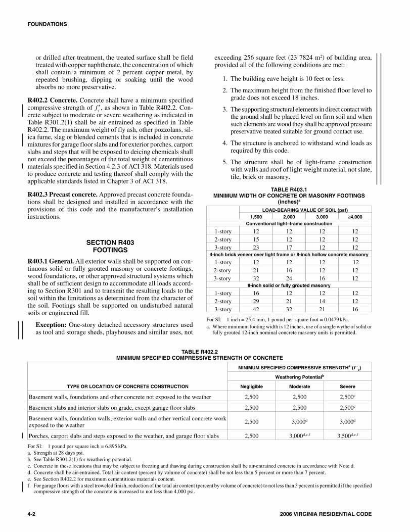
For SI: 1 inch = 25.4 mm.
FIGURE R403.1(1)CONCRETE AND MASONRY FOUNDATION DETAILS
304_Va_Res_2006.psM:\data\CODES\STATE CODES\Virginia\2006\Residential Code\Final VP\04_Va_Res_2006.vpThursday, April 10, 2008 11:08:02 AM
Color profile: Generic CMYK printer profileComposite Default screen
R403.1.1 Minimum size. Minimum sizes for concrete andmasonry footings shall be as set forth in Table R403.1 andFigure R403.1(1). The footing width, W, shall be based onthe load-bearing value of the soil in accordance with TableR401.4.1. Spread footings shall be at least 6 inches (152mm) thick. Footing projections, P, shall be at least 2 inches(51 mm) and shall not exceed the thickness of the footing.The size of footings supporting piers and columns shall bebased on the tributary load and allowable soil pressure inaccordance with Table R401.4.1. Footings for wood foun-dations shall be in accordance with the details set forth inSection R403.2, and Figures R403.1(2) and R403.1(3).
R403.1.2 Continuous footing in Seismic Design Catego-ries D0, D1 and D2. The braced wall panels at exterior wallsof buildings located in Seismic Design Categories D0, D1
and D2 shall be supported by continuous footings. Allrequired interior braced wall panels in buildings with plandimensions greater than 50 feet (15 240 mm) shall also besupported by continuous footings.
R403.1.3 Seismic reinforcing. Concrete footings located inSeismic Design Categories D0, D1 and D2, as established inTable R301.2(1), shall have minimum reinforcement. Bot-tom reinforcement shall be located a minimum of 3 inches(76 mm) clear from the bottom of the footing.
In Seismic Design Categories D0, D1 and D2 where a con-struction joint is created between a concrete footing and astem wall, a minimum of one No. 4 bar shall be installed atnot more than 4 feet (1219 mm) on center. The vertical barshall extend to 3 inches (76 mm) clear of the bottom of thefooting, have a standard hook and extend a minimum of 14inches (357 mm) into the stem wall.
In Seismic Design Categories D0, D1 and D2 where agrouted masonry stem wall is supported on a concrete foot-ing and stem wall, a minimum of one No. 4 bar shall beinstalled at not more than 4 feet on center. The vertical barshall extend to 3 inches (76 mm) clear of the bottom of thefooting and have a standard hook.
4-4 2006 VIRGINIA RESIDENTIAL CODE
FOUNDATIONS
s
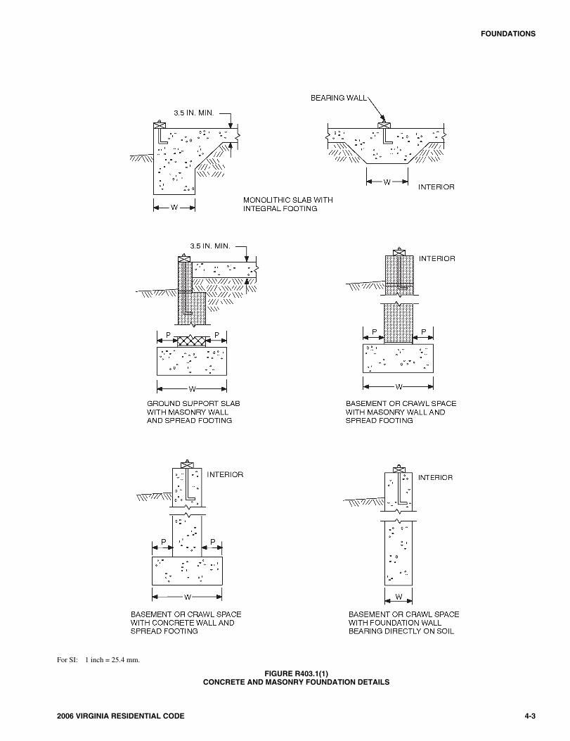
8 IN.
PRESSURE-PRESERVATIVE TREATED
FLASHING
FIELD-APPLIED 2 × 6 IN. TOP PLATE
2 × 6 IN. TOP PLATE
2 × 6 IN. STUD WALL INSULATEDAS APPROPRIATE AND WARM SIDEVAPOR BARRIER
1 IN. THICK PRESSURE-PRESERVATIVETREATED LUMBER OR PLYWOOD STRIPPROTECTING TOP OF POLYETHYLENE FILM
2 IN. AIR GAP
PRESSURE-PRESERVATIVETREATED PLYWOOD(SEE TABLE R404.2.3)
6 MIL POLYETHYLENE FILM
6 MIL POLYETHYLENE FILMON CRUSHED STONE ORGRAVEL BACKFILL
MIN. 3.5 IN. CONCRETE SLAB WITHVAPOR BARRIER AND OPTIONAL1 IN. SCREED BOARD
4 IN. GRAVEL OR CRUSHEDSTONE FILL UNDER FLOOR(SEE SECTION R403.2)
PRESSURE-PRESERVATIVETREATED 2 6 IN. BOTTOM PLATE×
PRESSURE-PRESERVATIVETREATED 2 8 IN. FOOTING PLATE×
FINISH GRADE SLOPE 12/ IN.
PER FOOT, MIN. 6 FT FROMWALL
4 FT (MAX. BACKFILL)
8 IN.
16 IN.
For SI: 1 inch 25.4 = mm, 1 foot =304.8, 1 mil =0.0254 mm.
FIGURE R403.1(2)PERMANENT WOOD FOUNDATION BASEMENT WALL SECTION
404_Va_Res_2006.psM:\data\CODES\STATE CODES\Virginia\2006\Residential Code\Final VP\04_Va_Res_2006.vpThursday, April 10, 2008 11:08:03 AM
Color profile: Generic CMYK printer profileComposite Default screen
In Seismic Design Categories D0, D1 and D2 masonrystem walls without solid grout and vertical reinforcing arenot permitted.
Exception: In detached one- and two-family dwellingswhich are three stories or less in height and constructedwith stud bearing walls, plain concrete footings withoutlongitudinal reinforcement supporting walls and isolatedplain concrete footings supporting columns or pedestalsare permitted.
R403.1.3.1 Foundations with stemwalls. Foundationswith stem walls shall have installed a minimum of oneNo. 4 bar within 12 inches (305 mm) of the top of the walland one No. 4 bar located 3 inches (76 mm) to 4 inches(102 mm) from the bottom of the footing.
R403.1.3.2 Slabs-on-ground with turned-down foot-ings. Slabs-on-ground with turned-down footings shallhave a minimum of one No. 4 bar at the top and bottom ofthe footing.
Exception: For slabs-on-ground cast monolithicallywith a footing, one No. 5 bar or two No. 4 bars shall belocated in the middle third of the footing depth.
R403.1.4 Minimum depth. All exterior footings shall beplaced at least 12 inches (305 mm) below the undisturbedground surface. Where applicable, the depth of footings shallalso conform to Sections R403.1.4.1 through R403.1.4.2.
R403.1.4.1 Frost protection. Except where otherwiseprotected from frost, foundation walls, piers and otherpermanent supports of buildings and structures shall beprotected from frost by one or more of the followingmethods:
1. Extended below the frost line specified in TableR301.2.(1);
2. Constructing in accordance with Section R403.3;
3. Constructing in accordance with ASCE 32; or
4. Erected on solid rock.
Exceptions:
1. Protection of freestanding accessorystructures with an area of 600 square feet(56 m2) or less, of light-framed construc-tion, with an eave height of 10 feet (3048mm) or less shall not be required.
2. Protection of freestanding accessorystructures with an area of 400 square feet(37 m2) or less, of other than light-framedconstruction, with an eave height of 10feet (3048 mm) or less shall not berequired.
2006 VIRGINIA RESIDENTIAL CODE 4-5
FOUNDATIONS
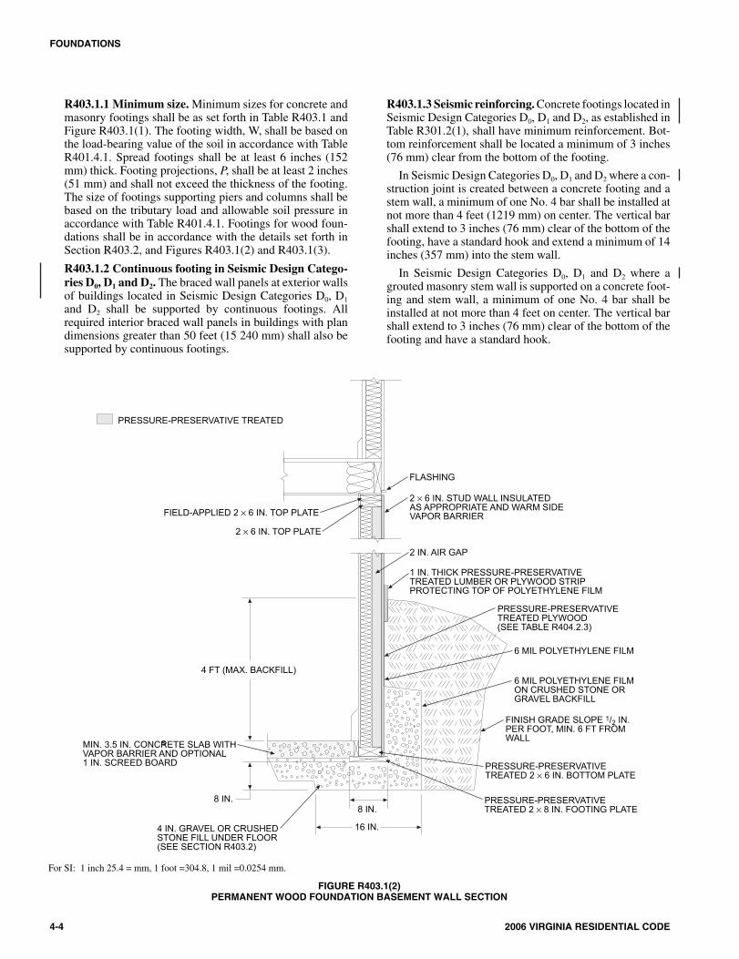
PRESSURE-PRESERVATIVE TREATED
FIELD-APPLIED 2 × 6 IN. TOP PLATE
6 IN.
8 IN. 4 IN.4 IN.
FLOOR JOIST
FLASHING
2 × 6 IN. TOP PLATE
PRESSURE-PRESERVATIVETREATED PLYWOOD(SEE TABLE R404.2.3)
6 IN. GRAVEL OR CRUSHED STONE(SEE SECTION R403.2)
PRESSURE-PRESERVATIVETREATED 2 6 IN. STUD WALL×
6 MIL POLYETHYLENE FILM
FINISH GRADE SLOPE 12/ IN.
PER FOOT, MIN. 6 FT FROMWALL
PRESSURE-PRESERVATIVETREATED 2 6 IN. BOTTOM PLATE×
PRESSURE-PRESERVATIVETREATED 2 8 IN. FOOTING PLATE×
BELOW FROST LINE
8 IN. MIN.
18 IN. MIN.
(NOMINALDIMENSIONS)
For SI: 1 inch = 25.4 mm, 1 foot = 304.8 mm, 1 mil = 0.0254 mm.
FIGURE R403.1(3)PERMANENT WOOD FOUNDATION CRAWL SPACE SECTION
504_Va_Res_2006.psM:\data\CODES\STATE CODES\Virginia\2006\Residential Code\Final VP\04_Va_Res_2006.vpThursday, April 10, 2008 11:08:04 AM
Color profile: Generic CMYK printer profileComposite Default screen
3. Decks not supported by a dwelling neednot be provided with footings that extendbelow the frost line.
Footings shall not bear on frozen soil unless the frozencondition is permanent.
R403.1.4.2 Seismic conditions. In Seismic Design Cat-egories D0, D1 and D2, interior footings supporting bear-ing or bracing walls and cast monolithically with a slabon grade shall extend to a depth of not less than 12 inches(305 mm) below the top of the slab.
R403.1.5 Slope. The top surface of footings shall be level.The bottom surface of footings shall not have a slope exceed-ing one unit vertical in 10 units horizontal (10-percent slope).Footings shall be stepped where it is necessary to change theelevation of the top surface of the footings or where the slopeof the bottom surface of the footings will exceed one unit ver-tical in 10 units horizontal (10-percent slope).
R403.1.6 Foundation anchorage. When braced wall panelsare supported directly on continuous foundations, the wallwood sill plate or cold-formed steel bottom track shall beanchored to the foundation in accordance with this section.
The wood sole plate at exterior walls on monolithicslabs and wood sill plate shall be anchored to the founda-tion with anchor bolts spaced a maximum of 6 feet (1829mm) on center. There shall be a minimum of two bolts perplate section with one bolt located not more than 12 inches(305 mm) or less than seven bolt diameters from each endof the plate section. In Seismic Design Categories D0, D1
and D2, anchor bolts shall be spaced at 6 feet (1829 mm) oncenter and located within 12 inches (305 mm) of the endsof each plate section at interior braced wall lines whenrequired by Section R602.10.9 to be supported on a contin-uous foundation. Bolts shall be at least 1/2 inch (13 mm) indiameter and shall extend a minimum of 7 inches (178mm) into masonry or concrete. Interior bearing wall soleplates on monolithic slab foundation shall be positivelyanchored with approved fasteners. A nut and washer shallbe tightened on each bolt of the plate. Sills and sole platesshall be protected against decay and termites whererequired by Sections R319 and R320. Cold-formed steelframing systems shall be fastened to the wood sill plates oranchored directly to the foundation as required in SectionR505.3.1 or R603.1.1.
Exceptions:
1. Foundation anchorage, spaced as required to pro-vide equivalent anchorage to 1/2-inch-diameter (13mm) anchor bolts.
2. Walls 24 inches (610 mm) total length or shorterconnecting offset braced wall panels shall beanchored to the foundation with a minimum of oneanchor bolt located in the center third of the platesection and shall be attached to adjacent bracedwall panels per Figure R602.10.5 at corners.
3. Walls 12 inches (305 mm) total length or shorterconnecting offset braced wall panels shall be per-mitted to be connected to the foundation without
anchor bolts. The wall shall be attached to adjacentbraced wall panels per Figure R602.10.5 at corners.
R403.1.6.1 Foundation anchorage in Seismic DesignCategories C, D0, D1 and D2. In addition to the require-ments of Section R403.1.6, the following requirementsshall apply to wood light-frame structures in SeismicDesign Categories D0, D1 and D2 and wood light-frametownhouses in Seismic Design Category C.
1. Plate washers conforming to Section R602.11.1shall be provided for all anchor bolts over the fulllength of required braced wall lines. Properly sizedcut washers shall be permitted for anchor bolts inwall lines not containing braced wall panels.
2. Interior braced wall plates shall have anchor boltsspaced at not more than 6 feet (1829 mm) on centerand located within 12 inches (305 mm) of the endsof each plate section when supported on a continu-ous foundation.
3. Interior bearing wall sole plates shall have anchorbolts spaced at not more than 6 feet (1829 mm) oncenter and located within 12 inches (305 mm) ofthe ends of each plate section when supported on acontinuous foundation.
4. The maximum anchor bolt spacing shall be 4 feet(1219 mm) for buildings over two stories in height.
5. Stepped cripple walls shall conform to SectionR602.11.3.
6. Where continuous wood foundations in accor-dance with Section R404.2 are used, the forcetransfer shall have a capacity equal to or greaterthan the connections required by SectionR602.11.1 or the braced wall panel shall be con-nected to the wood foundations in accordance withthe braced wall panel-to-floor fastening require-ments of Table R602.3(1).
R403.1.7 Footings on or adjacent to slopes. The place-ment of buildings and structures on or adjacent to slopessteeper than 1 unit vertical in 3 units horizontal (33.3-per-cent slope) shall conform to Sections R403.1.7.1 throughR403.1.7.4.
R403.1.7.1 Building clearances from ascendingslopes. In general, buildings below slopes shall be set asufficient distance from the slope to provide protectionfrom slope drainage, erosion and shallow failures.Except as provided in Section R403.1.7.4 and FigureR403.1.7.1, the following criteria will be assumed toprovide this protection. Where the existing slope issteeper than one unit vertical in one unit horizontal(100-percent slope), the toe of the slope shall be assumedto be at the intersection of a horizontal plane drawn fromthe top of the foundation and a plane drawn tangent to theslope at an angle of 45 degrees (0.79 rad) to the horizon-tal. Where a retaining wall is constructed at the toe of theslope, the height of the slope shall be measured from thetop of the wall to the top of the slope.
4-6 2006 VIRGINIA RESIDENTIAL CODE
FOUNDATIONS
604_Va_Res_2006.psM:\data\CODES\STATE CODES\Virginia\2006\Residential Code\Final VP\04_Va_Res_2006.vpThursday, April 10, 2008 11:08:04 AM
Color profile: Generic CMYK printer profileComposite Default screen
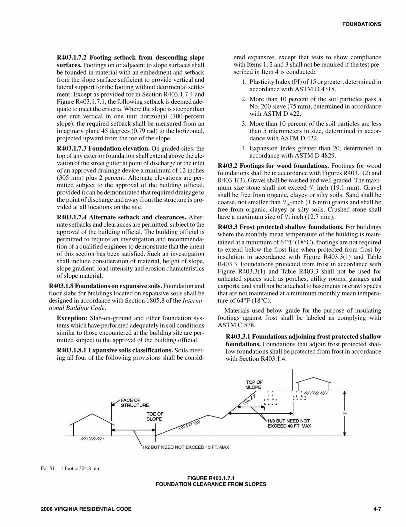
R403.1.7.2 Footing setback from descending slopesurfaces. Footings on or adjacent to slope surfaces shallbe founded in material with an embedment and setbackfrom the slope surface sufficient to provide vertical andlateral support for the footing without detrimental settle-ment. Except as provided for in Section R403.1.7.4 andFigure R403.1.7.1, the following setback is deemed ade-quate to meet the criteria. Where the slope is steeper thanone unit vertical in one unit horizontal (100-percentslope), the required setback shall be measured from animaginary plane 45 degrees (0.79 rad) to the horizontal,projected upward from the toe of the slope.
R403.1.7.3 Foundation elevation. On graded sites, thetop of any exterior foundation shall extend above the ele-vation of the street gutter at point of discharge or the inletof an approved drainage device a minimum of 12 inches(305 mm) plus 2 percent. Alternate elevations are per-mitted subject to the approval of the building official,provided it can be demonstrated that required drainage tothe point of discharge and away from the structure is pro-vided at all locations on the site.
R403.1.7.4 Alternate setback and clearances. Alter-nate setbacks and clearances are permitted, subject to theapproval of the building official. The building official ispermitted to require an investigation and recommenda-tion of a qualified engineer to demonstrate that the intentof this section has been satisfied. Such an investigationshall include consideration of material, height of slope,slope gradient, load intensity and erosion characteristicsof slope material.
R403.1.8 Foundations on expansive soils. Foundation andfloor slabs for buildings located on expansive soils shall bedesigned in accordance with Section 1805.8 of the Interna-tional Building Code.
Exception: Slab-on-ground and other foundation sys-tems which have performed adequately in soil conditionssimilar to those encountered at the building site are per-mitted subject to the approval of the building official.
R403.1.8.1 Expansive soils classifications. Soils meet-ing all four of the following provisions shall be consid-
ered expansive, except that tests to show compliancewith Items 1, 2 and 3 shall not be required if the test pre-scribed in Item 4 is conducted:
1. Plasticity Index (PI) of 15 or greater, determined inaccordance with ASTM D 4318.
2. More than 10 percent of the soil particles pass aNo. 200 sieve (75 mm), determined in accordancewith ASTM D 422.
3. More than 10 percent of the soil particles are lessthan 5 micrometers in size, determined in accor-dance with ASTM D 422.
4. Expansion Index greater than 20, determined inaccordance with ASTM D 4829.
R403.2 Footings for wood foundations. Footings for woodfoundations shall be in accordance with Figures R403.1(2) andR403.1(3). Gravel shall be washed and well graded. The maxi-mum size stone shall not exceed 3/4 inch (19.1 mm). Gravelshall be free from organic, clayey or silty soils. Sand shall becoarse, not smaller than 1/16-inch (1.6 mm) grains and shall befree from organic, clayey or silty soils. Crushed stone shallhave a maximum size of 1/2 inch (12.7 mm).
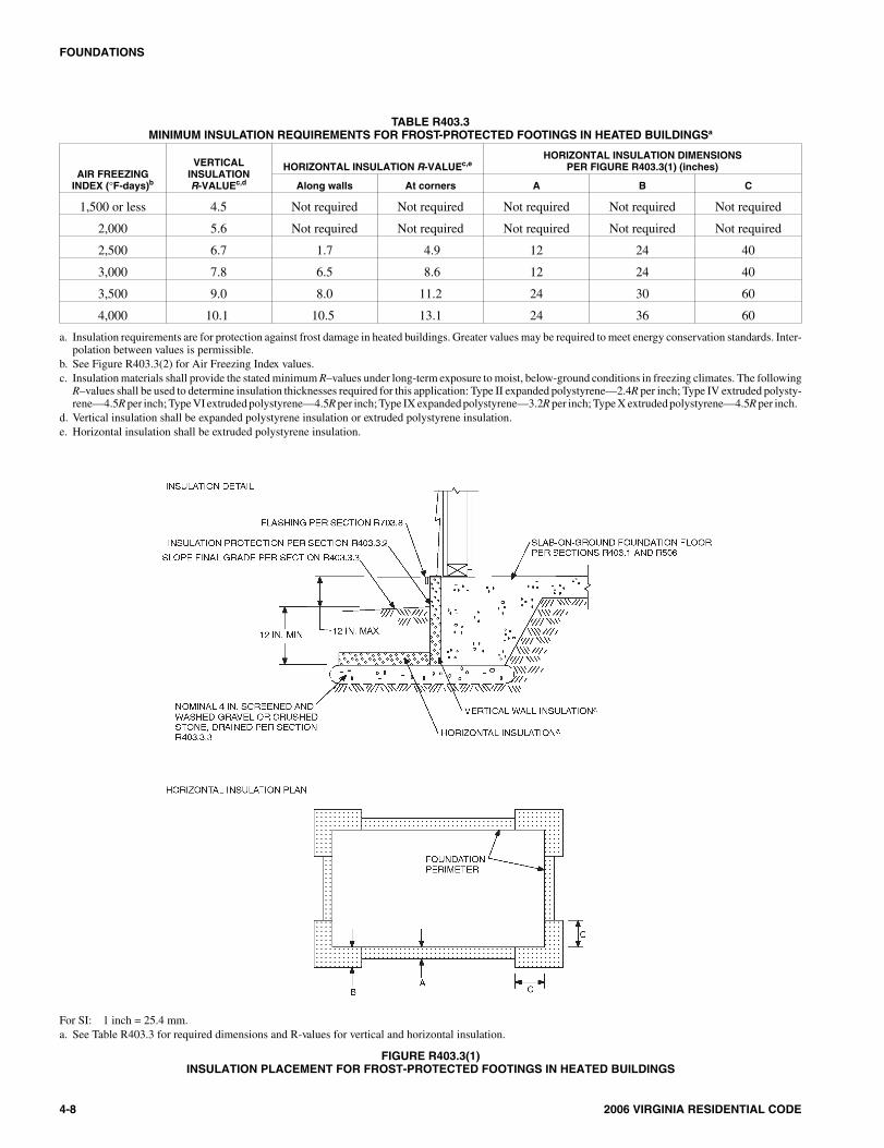
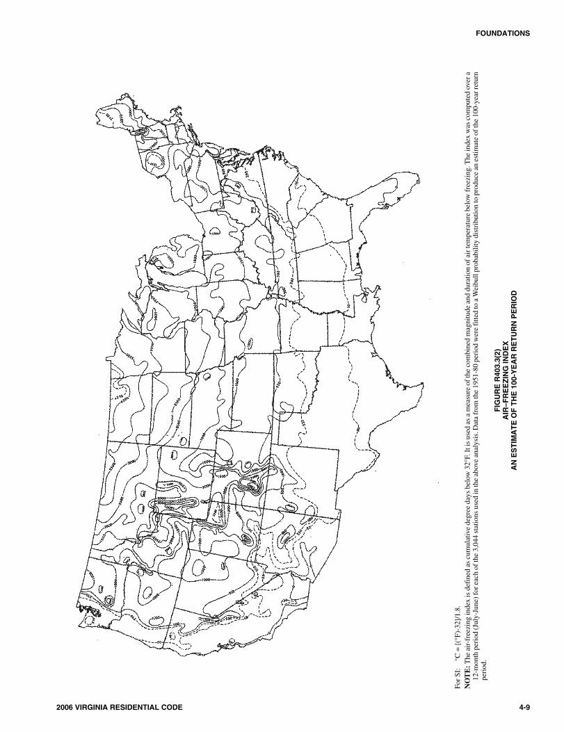
R403.3 Frost protected shallow foundations. For buildingswhere the monthly mean temperature of the building is main-tained at a minimum of 64°F (18°C), footings are not requiredto extend below the frost line when protected from frost byinsulation in accordance with Figure R403.3(1) and TableR403.3. Foundations protected from frost in accordance withFigure R403.3(1) and Table R403.3 shall not be used forunheated spaces such as porches, utility rooms, garages andcarports, and shall not be attached to basements or crawl spacesthat are not maintained at a minimum monthly mean tempera-ture of 64°F (18°C).
Materials used below grade for the purpose of insulatingfootings against frost shall be labeled as complying withASTM C 578.
R403.3.1 Foundations adjoining frost protected shallowfoundations. Foundations that adjoin frost protected shal-low foundations shall be protected from frost in accordancewith Section R403.1.4.
2006 VIRGINIA RESIDENTIAL CODE 4-7
FOUNDATIONS
For SI: 1 foot = 304.8 mm.
FIGURE R403.1.7.1FOUNDATION CLEARANCE FROM SLOPES
704_Va_Res_2006.psM:\data\CODES\STATE CODES\Virginia\2006\Residential Code\Final VP\04_Va_Res_2006.vpThursday, April 10, 2008 11:08:06 AM
Color profile: Generic CMYK printer profileComposite Default screen
4-8 2006 VIRGINIA RESIDENTIAL CODE
FOUNDATIONS
TABLE R403.3MINIMUM INSULATION REQUIREMENTS FOR FROST-PROTECTED FOOTINGS IN HEATED BUILDINGSa
AIR FREEZINGINDEX ( F-days)b
VERTICALINSULATIONR-VALUEc,d
HORIZONTAL INSULATION R-VALUEc,eHORIZONTAL INSULATION DIMENSIONS
PER FIGURE R403.3(1) (inches)
Along walls At corners A B C
1,500 or less 4.5 Not required Not required Not required Not required Not required
2,000 5.6 Not required Not required Not required Not required Not required
2,500 6.7 1.7 4.9 12 24 40
3,000 7.8 6.5 8.6 12 24 40
3,500 9.0 8.0 11.2 24 30 60
4,000 10.1 10.5 13.1 24 36 60
a. Insulation requirements are for protection against frost damage in heated buildings. Greater values may be required to meet energy conservation standards. Inter-polation between values is permissible.
b. See Figure R403.3(2) for Air Freezing Index values.c. Insulation materials shall provide the stated minimum R–values under long-term exposure to moist, below-ground conditions in freezing climates. The following
R–values shall be used to determine insulation thicknesses required for this application: Type II expanded polystyrene—2.4R per inch; Type IV extruded polysty-rene—4.5R per inch; Type VI extruded polystyrene—4.5R per inch; Type IX expanded polystyrene—3.2R per inch; Type X extruded polystyrene—4.5R per inch.
d. Vertical insulation shall be expanded polystyrene insulation or extruded polystyrene insulation.e. Horizontal insulation shall be extruded polystyrene insulation.
For SI: 1 inch = 25.4 mm.a. See Table R403.3 for required dimensions and R-values for vertical and horizontal insulation.
FIGURE R403.3(1)INSULATION PLACEMENT FOR FROST-PROTECTED FOOTINGS IN HEATED BUILDINGS
804_Va_Res_2006.psM:\data\CODES\STATE CODES\Virginia\2006\Residential Code\Final VP\04_Va_Res_2006.vpThursday, April 10, 2008 11:08:07 AM
Color profile: Generic CMYK printer profileComposite Default screen
2006 VIRGINIA RESIDENTIAL CODE 4-9
FOUNDATIONS
For
SI:
°C=
[(°F
)-32
]/1.
8.N
OT
E:T
heai
r-fr
eezi
ngin
dex
isde
fine
das
cum
ulat
ive
degr
eeda
ysbe
low
32°F
.Iti
sus
edas
am
easu
reof
the
com
bine
dm
agni
tude
and
dura
tion
ofai
rtem
pera
ture
belo
wfr
eezi
ng.T
hein
dex
was
com
pute
dov
era
12-m
onth
peri
od(J
uly-
June
)for
each
ofth
e3,
044
stat
ions
used
inth
eab
ove
anal
ysis
.Dat
afr
omth
e19
51-8
0pe
riod
wer
efi
tted
toa
Wei
bull
prob
abili
tydi
stri
butio
nto
prod
uce
anes
timat
eof
the
100-
year
retu
rnpe
riod
.
FIG
UR
ER
403.
3(2)
AIR
–FR
EE
ZIN
GIN
DE
XA
NE
ST
IMA
TE
OF
TH
E10
0-Y
EA
RR
ET
UR
NP
ER
IOD
904_Va_Res_2006.psM:\data\CODES\STATE CODES\Virginia\2006\Residential Code\Final VP\04_Va_Res_2006.vpThursday, April 10, 2008 11:08:12 AM
Color profile: Generic CMYK printer profileComposite Default screen
4-10 2006 VIRGINIA RESIDENTIAL CODE
FOUNDATIONS
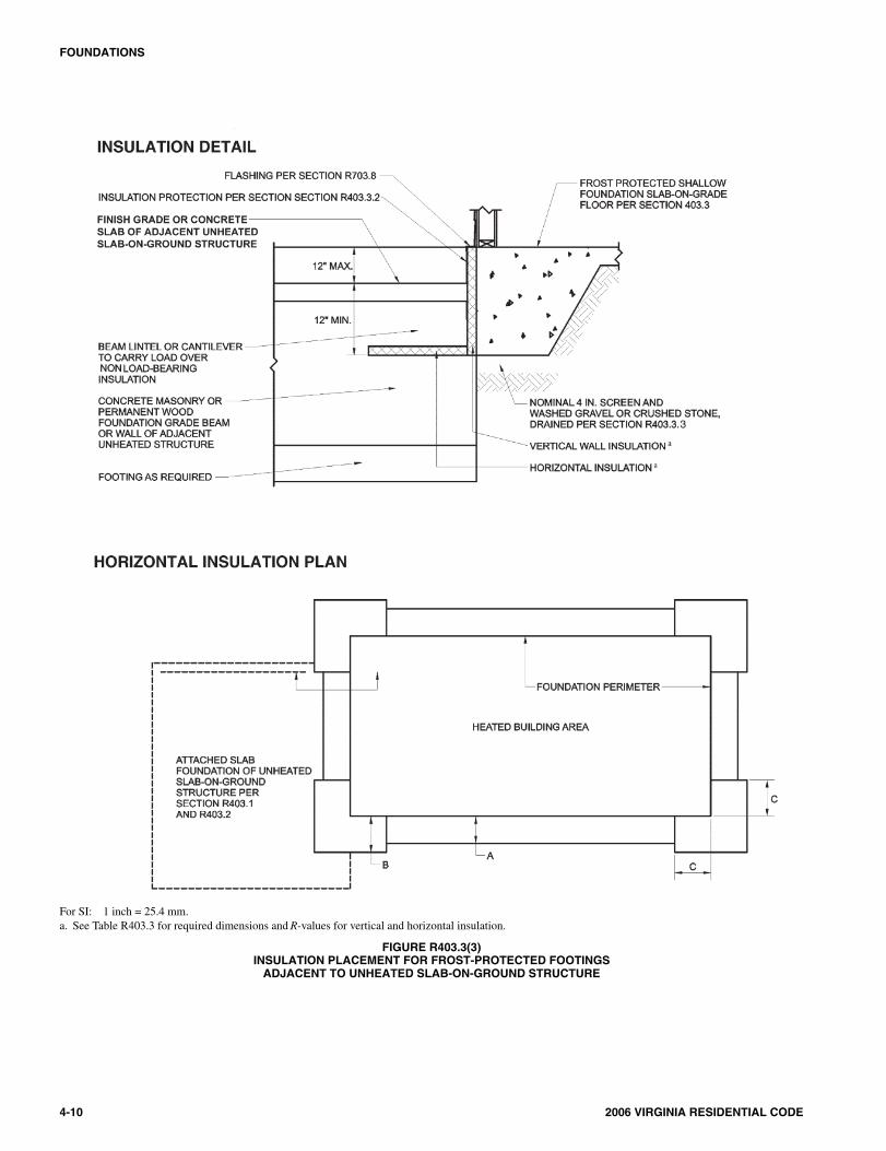
For SI: 1 inch = 25.4 mm.a. See Table R403.3 for required dimensions and R-values for vertical and horizontal insulation.
FIGURE R403.3(3)INSULATION PLACEMENT FOR FROST-PROTECTED FOOTINGS
ADJACENT TO UNHEATED SLAB-ON-GROUND STRUCTURE
1004_Va_Res_2006.psM:\data\CODES\STATE CODES\Virginia\2006\Residential Code\Final VP\04_Va_Res_2006.vpThursday, April 10, 2008 11:08:17 AM
Color profile: Generic CMYK printer profileComposite Default screen
R403 .3 .1 .1 At tachment to unheatedslab-on-ground structure. Vertical wall insulationand horizontal insulation of frost protected shallowfoundations that adjoin a slab-on-ground foundationthat does not have a monthly mean temperature main-tained at a minimum of 64°F (18°C), shall be in accor-dance with Figure R403.3(3) and Table R403.3.Vertical wall insulation shall extend between the frostprotected shallow foundation and the adjoining slabfoundation. Required horizontal insulation shall becontinuous under the adjoining slab foundation andthrough any foundation walls adjoining the frost pro-tected shallow foundation. Where insulation passesthrough a foundation wall, it shall either be of a typecomplying with this section and having bearing capac-ity equal to or greater than the structural loads imposedby the building, or the building shall be designed andconstructed using beams, lintels, cantilevers or othermeans of transferring building loads such that thestructural loads of the building do not bear on the insu-lation.
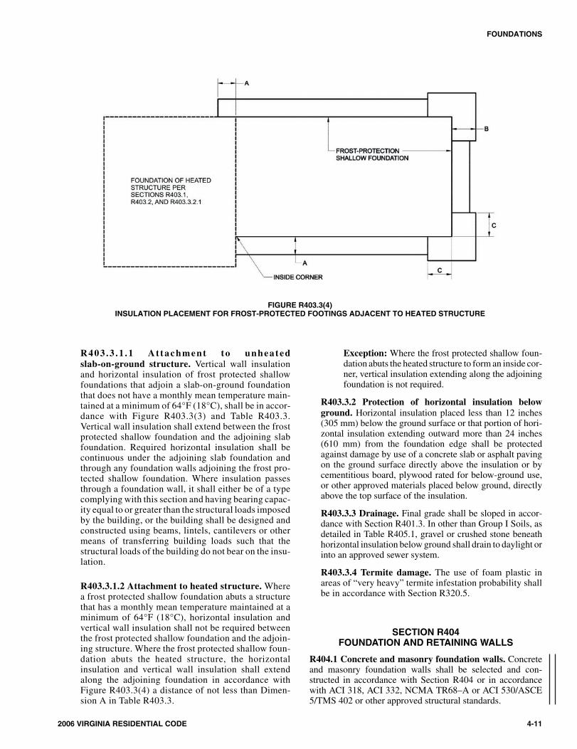
R403.3.1.2 Attachment to heated structure. Wherea frost protected shallow foundation abuts a structurethat has a monthly mean temperature maintained at aminimum of 64°F (18°C), horizontal insulation andvertical wall insulation shall not be required betweenthe frost protected shallow foundation and the adjoin-ing structure. Where the frost protected shallow foun-dation abuts the heated structure, the horizontalinsulation and vertical wall insulation shall extendalong the adjoining foundation in accordance withFigure R403.3(4) a distance of not less than Dimen-sion A in Table R403.3.
Exception: Where the frost protected shallow foun-dation abuts the heated structure to form an inside cor-ner, vertical insulation extending along the adjoiningfoundation is not required.
R403.3.2 Protection of horizontal insulation belowground. Horizontal insulation placed less than 12 inches(305 mm) below the ground surface or that portion of hori-zontal insulation extending outward more than 24 inches(610 mm) from the foundation edge shall be protectedagainst damage by use of a concrete slab or asphalt pavingon the ground surface directly above the insulation or bycementitious board, plywood rated for below-ground use,or other approved materials placed below ground, directlyabove the top surface of the insulation.
R403.3.3 Drainage. Final grade shall be sloped in accor-dance with Section R401.3. In other than Group I Soils, asdetailed in Table R405.1, gravel or crushed stone beneathhorizontal insulation below ground shall drain to daylight orinto an approved sewer system.
R403.3.4 Termite damage. The use of foam plastic inareas of “very heavy” termite infestation probability shallbe in accordance with Section R320.5.
SECTION R404FOUNDATION AND RETAINING WALLS
R404.1 Concrete and masonry foundation walls. Concreteand masonry foundation walls shall be selected and con-structed in accordance with Section R404 or in accordancewith ACI 318, ACI 332, NCMA TR68–A or ACI 530/ASCE5/TMS 402 or other approved structural standards.
2006 VIRGINIA RESIDENTIAL CODE 4-11
FOUNDATIONS
FIGURE R403.3(4)INSULATION PLACEMENT FOR FROST-PROTECTED FOOTINGS ADJACENT TO HEATED STRUCTURE
1104_Va_Res_2006.psM:\data\CODES\STATE CODES\Virginia\2006\Residential Code\Final VP\04_Va_Res_2006.vpThursday, April 10, 2008 11:08:31 AM
Color profile: Generic CMYK printer profileComposite Default screen
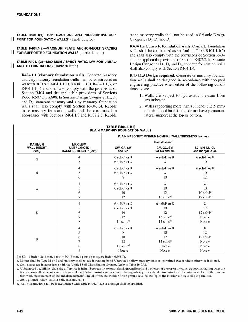
TABLE R404.1(1)—TOP REACTIONS AND PRESCRIPTIVE SUP-PORT FOR FOUNDATION WALLSa (Table deleted)
TABLE R404.1(2)—MAXIMUM PLATE ANCHOR-BOLT SPACINGFOR SUPPORTED FOUNDATION WALLa (Table deleted)
TABLE R404.1(3)—MAXIMUM ASPECT RATIO, L/W FOR UNBAL-ANCED FOUNDATIONS (Table deleted)
R404.1.1 Masonry foundation walls. Concrete masonryand clay masonry foundation walls shall be constructed asset forth in Table R404.1.1(1), R404.1.1(2), R404.1.1(3) orR404.1.1(4) and shall also comply with the provisions ofSection R404 and the applicable provisions of SectionsR606, R607 and R608. In Seismic Design Categories D0, D1
and D2, concrete masonry and clay masonry foundationwalls shall also comply with Section R404.1.4. Rubblestone masonry foundation walls shall be constructed inaccordance with Sections R404.1.8 and R607.2.2. Rubble
stone masonry walls shall not be used in Seismic DesignCategories D0, D1 and D2.
R404.1.2 Concrete foundation walls. Concrete foundationwalls shall be constructed as set forth in Table R404.1.1(5)and shall also comply with the provisions of Section R404and the applicable provisions of Section R402.2. In SeismicDesign Categories D0, D1 and D2, concrete foundation wallsshall also comply with Section R404.1.4.
R404.1.3 Design required. Concrete or masonry founda-tion walls shall be designed in accordance with acceptedengineering practice when either of the following condi-tions exists:
1. Walls are subject to hydrostatic pressure fromgroundwater.
2. Walls supporting more than 48 inches (1219 mm)of unbalanced backfill that do not have permanentlateral support at the top or bottom.
4-12 2006 VIRGINIA RESIDENTIAL CODE
FOUNDATIONS
TABLE R404.1.1(1)PLAIN MASONRY FOUNDATION WALLS
MAXIMUMWALL HEIGHT
(feet)
MAXIMUMUNBALANCED
BACKFILL HEIGHTc (feet)
PLAIN MASONRYa MINIMUM NOMINAL WALL THICKNESS (inches)
Soil classesb
GW, GP, SWand SP
GM, GC, SM,SM-SC and ML
SC, MH, ML-CLand inorganic CL
545
6 solidd or 86 solidd or 8
6 solidd or 88
6 solidd or 810
6456
6 solidd or 86 solidd or 8
8
6 solidd or 8810
6 solidd or 81012
7
4567
6 solidd or 86 solidd or 8
1012
81012
10 solidd
810
10 solidd
12 solidd
8
45678
6 solidd or 86 solidd or 8
1012
10 solidd
6 solidd or 81012
12 solidd
12 solidd
812
12 solidd
Note eNote e
9
456789
6 solidd or 881012
12 solidd
Note e
6 solidd or 81012
12 solidd
Note eNote e
812
12 solidd
Note eNote eNote e
For SI: 1 inch = 25.4 mm, 1 foot = 304.8 mm, 1 pound per square inch = 6.895 Pa.a. Mortar shall be Type M or S and masonry shall be laid in running bond. Ungrouted hollow masonry units are permitted except where otherwise indicated.b. Soil classes are in accordance with the Unified Soil Classification System. Refer to Table R405.1.c. Unbalanced backfill height is the difference in height between the exterior finish ground level and the lower of the top of the concrete footing that supports the
foundation wall or the interior finish ground level. Where an interior concrete slab-on-grade is provided and is in contact with the interior surface of the founda-tion wall, measurement of the unbalanced backfill height from the exterior finish ground level to the top of the interior concrete slab is permitted.
d. Solid grouted hollow units or solid masonry units.e. Wall construction shall be in accordance with Table R404.1.1(2) or a design shall be provided.
1204_Va_Res_2006.psM:\data\CODES\STATE CODES\Virginia\2006\Residential Code\Final VP\04_Va_Res_2006.vpThursday, April 10, 2008 11:08:32 AM
Color profile: Generic CMYK printer profileComposite Default screen
2006 VIRGINIA RESIDENTIAL CODE 4-13
FOUNDATIONS
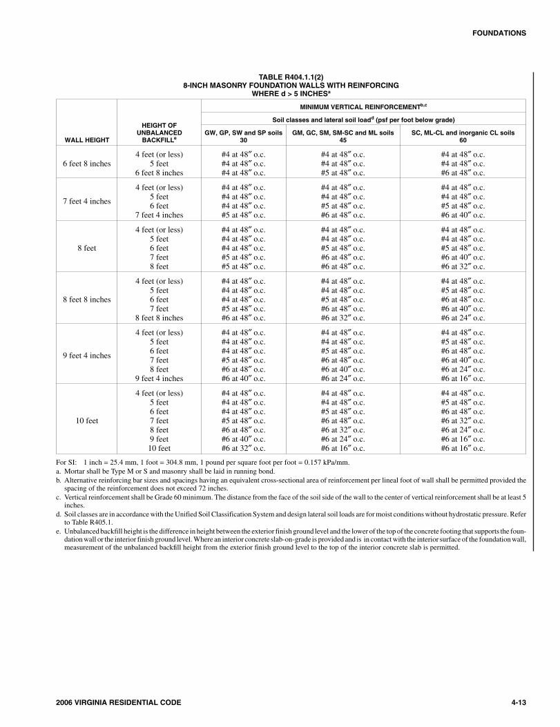
TABLE R404.1.1(2)8-INCH MASONRY FOUNDATION WALLS WITH REINFORCING
WHERE d > 5 INCHESa
WALL HEIGHT
HEIGHT OFUNBALANCED
BACKFILLe
MINIMUM VERTICAL REINFORCEMENTb,c
Soil classes and lateral soil loadd (psf per foot below grade)
GW, GP, SW and SP soils30
GM, GC, SM, SM-SC and ML soils45
SC, ML-CL and inorganic CL soils60
6 feet 8 inches4 feet (or less)
5 feet6 feet 8 inches
#4 at 48″ o.c.#4 at 48″ o.c.#4 at 48″ o.c.
#4 at 48″ o.c.#4 at 48″ o.c.#5 at 48″ o.c.
#4 at 48″ o.c.#4 at 48″ o.c.#6 at 48″ o.c.
7 feet 4 inches
4 feet (or less)5 feet6 feet
7 feet 4 inches
#4 at 48″ o.c.#4 at 48″ o.c.#4 at 48″ o.c.#5 at 48″ o.c.
#4 at 48″ o.c.#4 at 48″ o.c.#5 at 48″ o.c.#6 at 48″ o.c.
#4 at 48″ o.c.#4 at 48″ o.c.#5 at 48″ o.c.#6 at 40″ o.c.
8 feet
4 feet (or less)5 feet6 feet7 feet8 feet
#4 at 48″ o.c.#4 at 48″ o.c.#4 at 48″ o.c.#5 at 48″ o.c.#5 at 48″ o.c.
#4 at 48″ o.c.#4 at 48″ o.c.#5 at 48″ o.c.#6 at 48″ o.c.#6 at 48″ o.c.
#4 at 48″ o.c.#4 at 48″ o.c.#5 at 48″ o.c.#6 at 40″ o.c.#6 at 32″ o.c.
8 feet 8 inches
4 feet (or less)5 feet6 feet7 feet
8 feet 8 inches
#4 at 48″ o.c.#4 at 48″ o.c.#4 at 48″ o.c.#5 at 48″ o.c.#6 at 48″ o.c.
#4 at 48″ o.c.#4 at 48″ o.c.#5 at 48″ o.c.#6 at 48″ o.c.#6 at 32″ o.c.
#4 at 48″ o.c.#5 at 48″ o.c.#6 at 48″ o.c.#6 at 40″ o.c.#6 at 24″ o.c.
9 feet 4 inches
4 feet (or less)5 feet6 feet7 feet8 feet
9 feet 4 inches
#4 at 48″ o.c.#4 at 48″ o.c.#4 at 48″ o.c.#5 at 48″ o.c.#6 at 48″ o.c.#6 at 40″ o.c.
#4 at 48″ o.c.#4 at 48″ o.c.#5 at 48″ o.c.#6 at 48″ o.c.#6 at 40″ o.c.#6 at 24″ o.c.
#4 at 48″ o.c.#5 at 48″ o.c.#6 at 48″ o.c.#6 at 40″ o.c.#6 at 24″ o.c.#6 at 16″ o.c.
10 feet
4 feet (or less)5 feet6 feet7 feet8 feet9 feet10 feet
#4 at 48″ o.c.#4 at 48″ o.c.#4 at 48″ o.c.#5 at 48″ o.c.#6 at 48″ o.c.#6 at 40″ o.c.#6 at 32″ o.c.
#4 at 48″ o.c.#4 at 48″ o.c.#5 at 48″ o.c.#6 at 48″ o.c.#6 at 32″ o.c.#6 at 24″ o.c.#6 at 16″ o.c.
#4 at 48″ o.c.#5 at 48″ o.c.#6 at 48″ o.c.#6 at 32″ o.c.#6 at 24″ o.c.#6 at 16″ o.c.#6 at 16″ o.c.
For SI: 1 inch = 25.4 mm, 1 foot = 304.8 mm, 1 pound per square foot per foot = 0.157 kPa/mm.a. Mortar shall be Type M or S and masonry shall be laid in running bond.b. Alternative reinforcing bar sizes and spacings having an equivalent cross-sectional area of reinforcement per lineal foot of wall shall be permitted provided the
spacing of the reinforcement does not exceed 72 inches.c. Vertical reinforcement shall be Grade 60 minimum. The distance from the face of the soil side of the wall to the center of vertical reinforcement shall be at least 5
inches.d. Soil classes are in accordance with the Unified Soil Classification System and design lateral soil loads are for moist conditions without hydrostatic pressure. Refer
to Table R405.1.e. Unbalanced backfill height is the difference in height between the exterior finish ground level and the lower of the top of the concrete footing that supports the foun-
dation wall or the interior finish ground level. Where an interior concrete slab-on-grade is provided and is in contact with the interior surface of the foundationwall,measurement of the unbalanced backfill height from the exterior finish ground level to the top of the interior concrete slab is permitted.
1304_Va_Res_2006.psM:\data\CODES\STATE CODES\Virginia\2006\Residential Code\Final VP\04_Va_Res_2006.vpThursday, April 10, 2008 11:08:32 AM
Color profile: Generic CMYK printer profileComposite Default screen
4-14 2006 VIRGINIA RESIDENTIAL CODE
FOUNDATIONS
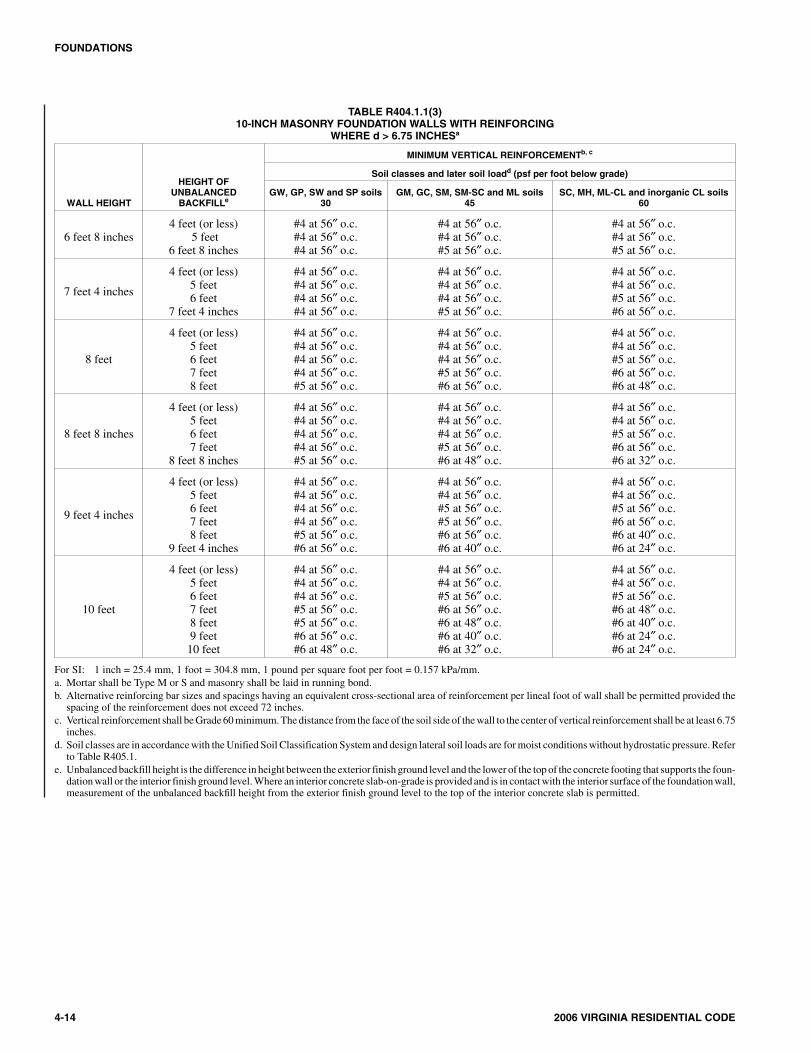
TABLE R404.1.1(3)10-INCH MASONRY FOUNDATION WALLS WITH REINFORCING
WHERE d > 6.75 INCHESa
WALL HEIGHT
HEIGHT OFUNBALANCED
BACKFILLe
MINIMUM VERTICAL REINFORCEMENTb, c
Soil classes and later soil loadd (psf per foot below grade)
GW, GP, SW and SP soils30
GM, GC, SM, SM-SC and ML soils45
SC, MH, ML-CL and inorganic CL soils60
6 feet 8 inches4 feet (or less)
5 feet6 feet 8 inches
#4 at 56″ o.c.#4 at 56″ o.c.#4 at 56″ o.c.
#4 at 56″ o.c.#4 at 56″ o.c.#5 at 56″ o.c.
#4 at 56″ o.c.#4 at 56″ o.c.#5 at 56″ o.c.
7 feet 4 inches
4 feet (or less)5 feet6 feet
7 feet 4 inches
#4 at 56″ o.c.#4 at 56″ o.c.#4 at 56″ o.c.#4 at 56″ o.c.
#4 at 56″ o.c.#4 at 56″ o.c.#4 at 56″ o.c.#5 at 56″ o.c.
#4 at 56″ o.c.#4 at 56″ o.c.#5 at 56″ o.c.#6 at 56″ o.c.
8 feet
4 feet (or less)5 feet6 feet7 feet8 feet
#4 at 56″ o.c.#4 at 56″ o.c.#4 at 56″ o.c.#4 at 56″ o.c.#5 at 56″ o.c.
#4 at 56″ o.c.#4 at 56″ o.c.#4 at 56″ o.c.#5 at 56″ o.c.#6 at 56″ o.c.
#4 at 56″ o.c.#4 at 56″ o.c.#5 at 56″ o.c.#6 at 56″ o.c.#6 at 48″ o.c.
8 feet 8 inches
4 feet (or less)5 feet6 feet7 feet
8 feet 8 inches
#4 at 56″ o.c.#4 at 56″ o.c.#4 at 56″ o.c.#4 at 56″ o.c.#5 at 56″ o.c.
#4 at 56″ o.c.#4 at 56″ o.c.#4 at 56″ o.c.#5 at 56″ o.c.#6 at 48″ o.c.
#4 at 56″ o.c.#4 at 56″ o.c.#5 at 56″ o.c.#6 at 56″ o.c.#6 at 32″ o.c.
9 feet 4 inches
4 feet (or less)5 feet6 feet7 feet8 feet
9 feet 4 inches
#4 at 56″ o.c.#4 at 56″ o.c.#4 at 56″ o.c.#4 at 56″ o.c.#5 at 56″ o.c.#6 at 56″ o.c.
#4 at 56″ o.c.#4 at 56″ o.c.#5 at 56″ o.c.#5 at 56″ o.c.#6 at 56″ o.c.#6 at 40″ o.c.
#4 at 56″ o.c.#4 at 56″ o.c.#5 at 56″ o.c.#6 at 56″ o.c.#6 at 40″ o.c.#6 at 24″ o.c.
10 feet
4 feet (or less)5 feet6 feet7 feet8 feet9 feet10 feet
#4 at 56″ o.c.#4 at 56″ o.c.#4 at 56″ o.c.#5 at 56″ o.c.#5 at 56″ o.c.#6 at 56″ o.c.#6 at 48″ o.c.
#4 at 56″ o.c.#4 at 56″ o.c.#5 at 56″ o.c.#6 at 56″ o.c.#6 at 48″ o.c.#6 at 40″ o.c.#6 at 32″ o.c.
#4 at 56″ o.c.#4 at 56″ o.c.#5 at 56″ o.c.#6 at 48″ o.c.#6 at 40″ o.c.#6 at 24″ o.c.#6 at 24″ o.c.
For SI: 1 inch = 25.4 mm, 1 foot = 304.8 mm, 1 pound per square foot per foot = 0.157 kPa/mm.a. Mortar shall be Type M or S and masonry shall be laid in running bond.b. Alternative reinforcing bar sizes and spacings having an equivalent cross-sectional area of reinforcement per lineal foot of wall shall be permitted provided the
spacing of the reinforcement does not exceed 72 inches.c. Vertical reinforcement shall be Grade 60 minimum. The distance from the face of the soil side of the wall to the center of vertical reinforcement shall be at least 6.75
inches.d. Soil classes are in accordance with the Unified Soil Classification System and design lateral soil loads are for moist conditions without hydrostatic pressure. Refer
to Table R405.1.e. Unbalanced backfill height is the difference in height between the exterior finish ground level and the lower of the top of the concrete footing that supports the foun-
dation wall or the interior finish ground level. Where an interior concrete slab-on-grade is provided and is in contact with the interior surface of the foundation wall,measurement of the unbalanced backfill height from the exterior finish ground level to the top of the interior concrete slab is permitted.
1404_Va_Res_2006.psM:\data\CODES\STATE CODES\Virginia\2006\Residential Code\Final VP\04_Va_Res_2006.vpThursday, April 10, 2008 11:08:32 AM
Color profile: Generic CMYK printer profileComposite Default screen
2006 VIRGINIA RESIDENTIAL CODE 4-15
FOUNDATIONS
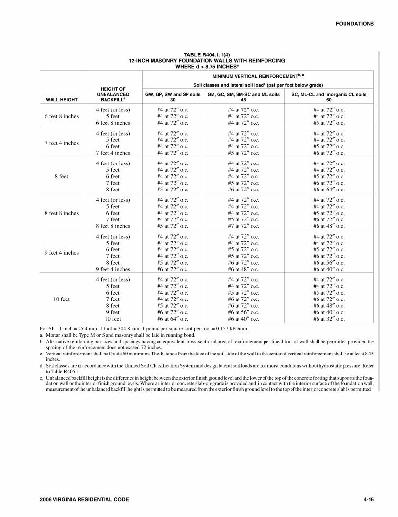
TABLE R404.1.1(4)12-INCH MASONRY FOUNDATION WALLS WITH REINFORCING
WHERE d > 8.75 INCHESa
WALL HEIGHT
HEIGHT OFUNBALANCED
BACKFILLe
MINIMUM VERTICAL REINFORCEMENTb, c
Soil classes and lateral soil loadd (psf per foot below grade)
GW, GP, SW and SP soils30
GM, GC, SM, SM-SC and ML soils45
SC, ML-CL and inorganic CL soils60
6 feet 8 inches4 feet (or less)
5 feet6 feet 8 inches
#4 at 72″ o.c.#4 at 72″ o.c.#4 at 72″ o.c.
#4 at 72″ o.c.#4 at 72″ o.c.#4 at 72″ o.c.
#4 at 72″ o.c.#4 at 72″ o.c.#5 at 72″ o.c.
7 feet 4 inches
4 feet (or less)5 feet6 feet
7 feet 4 inches
#4 at 72″ o.c.#4 at 72″ o.c.#4 at 72″ o.c.#4 at 72″ o.c.
#4 at 72″ o.c.#4 at 72″ o.c.#4 at 72″ o.c.#5 at 72″ o.c.
#4 at 72″ o.c.#4 at 72″ o.c.#5 at 72″ o.c.#6 at 72″ o.c.
8 feet
4 feet (or less)5 feet6 feet7 feet8 feet
#4 at 72″ o.c.#4 at 72″ o.c.#4 at 72″ o.c.#4 at 72″ o.c.#5 at 72″ o.c.
#4 at 72″ o.c.#4 at 72″ o.c.#4 at 72″ o.c.#5 at 72″ o.c.#6 at 72″ o.c.
#4 at 72″ o.c.#4 at 72″ o.c.#5 at 72″ o.c.#6 at 72″ o.c.#6 at 64″ o.c.
8 feet 8 inches
4 feet (or less)5 feet6 feet7 feet
8 feet 8 inches
#4 at 72″ o.c.#4 at 72″ o.c.#4 at 72″ o.c.#4 at 72″ o.c.#5 at 72″ o.c.
#4 at 72″ o.c.#4 at 72″ o.c.#4 at 72″ o.c.#5 at 72″ o.c.#7 at 72″ o.c.
#4 at 72″ o.c.#4 at 72″ o.c.#5 at 72″ o.c.#6 at 72″ o.c.#6 at 48″ o.c.
9 feet 4 inches
4 feet (or less)5 feet6 feet7 feet8 feet
9 feet 4 inches
#4 at 72″ o.c.#4 at 72″ o.c.#4 at 72″ o.c.#4 at 72″ o.c.#5 at 72″ o.c.#6 at 72″ o.c.
#4 at 72″ o.c.#4 at 72″ o.c.#5 at 72″ o.c.#5 at 72″ o.c.#6 at 72″ o.c.#6 at 48″ o.c.
#4 at 72″ o.c.#4 at 72″ o.c.#5 at 72″ o.c.#6 at 72″ o.c.#6 at 56″ o.c.#6 at 40″ o.c.
10 feet
4 feet (or less)5 feet6 feet7 feet8 feet9 feet10 feet
#4 at 72″ o.c.#4 at 72″ o.c.#4 at 72″ o.c.#4 at 72″ o.c.#5 at 72″ o.c.#6 at 72″ o.c.#6 at 64″ o.c.
#4 at 72″ o.c.#4 at 72″ o.c.#5 at 72″ o.c.#6 at 72″ o.c.#6 at 72″ o.c.#6 at 56″ o.c.#6 at 40″ o.c.
#4 at 72″ o.c.#4 at 72″ o.c.#5 at 72″ o.c.#6 at 72″ o.c.#6 at 48″ o.c.#6 at 40″ o.c.#6 at 32″ o.c.
For SI: 1 inch = 25.4 mm, 1 foot = 304.8 mm, 1 pound per square foot per foot = 0.157 kPa/mm.a. Mortar shall be Type M or S and masonry shall be laid in running bond.b. Alternative reinforcing bar sizes and spacings having an equivalent cross-sectional area of reinforcement per lineal foot of wall shall be permitted provided the
spacing of the reinforcement does not exceed 72 inches.c. Vertical reinforcement shall be Grade 60 minimum. The distance from the face of the soil side of the wall to the center of vertical reinforcement shall be at least 8.75
inches.d. Soil classes are in accordance with the Unified Soil Classification System and design lateral soil loads are for moist conditions without hydrostatic pressure. Refer
to Table R405.1.e. Unbalanced backfill height is the difference in height between the exterior finish ground level and the lower of the top of the concrete footing that supports the foun-
dation wall or the interior finish ground levels. Where an interior concrete slab-on-grade is provided and in contact with the interior surface of the foundation wall,measurement of the unbalanced backfill height is permitted to be measured from the exterior finish ground level to the top of the interior concrete slab is permitted.
1504_Va_Res_2006.psM:\data\CODES\STATE CODES\Virginia\2006\Residential Code\Final VP\04_Va_Res_2006.vpThursday, April 10, 2008 11:08:32 AM
Color profile: Generic CMYK printer profileComposite Default screen
4-16 2006 VIRGINIA RESIDENTIAL CODE
FOUNDATIONS
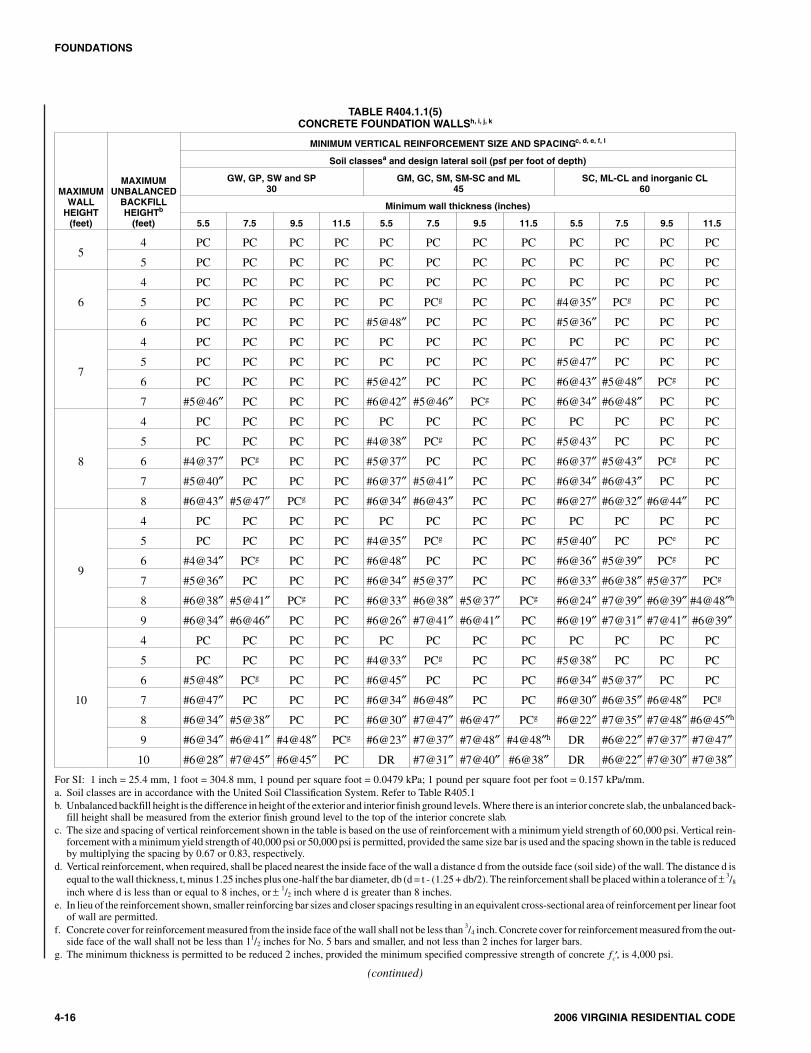
TABLE R404.1.1(5)CONCRETE FOUNDATION WALLSh, i, j, k
MAXIMUMWALL
HEIGHT(feet)
MAXIMUMUNBALANCED
BACKFILLHEIGHTb
(feet)
MINIMUM VERTICAL REINFORCEMENT SIZE AND SPACINGc, d, e, f, l
Soil classesa and design lateral soil (psf per foot of depth)
GW, GP, SW and SP30
GM, GC, SM, SM-SC and ML45
SC, ML-CL and inorganic CL60
Minimum wall thickness (inches)
5.5 7.5 9.5 11.5 5.5 7.5 9.5 11.5 5.5 7.5 9.5 11.5
54 PC PC PC PC PC PC PC PC PC PC PC PC
5 PC PC PC PC PC PC PC PC PC PC PC PC
6
4 PC PC PC PC PC PC PC PC PC PC PC PC
5 PC PC PC PC PC PCg PC PC #4@35″ PCg PC PC
6 PC PC PC PC #5@48″ PC PC PC #5@36″ PC PC PC
7
4 PC PC PC PC PC PC PC PC PC PC PC PC
5 PC PC PC PC PC PC PC PC #5@47″ PC PC PC
6 PC PC PC PC #5@42″ PC PC PC #6@43″ #5@48″ PCg PC
7 #5@46″ PC PC PC #6@42″ #5@46″ PCg PC #6@34″ #6@48″ PC PC
8
4 PC PC PC PC PC PC PC PC PC PC PC PC
5 PC PC PC PC #4@38″ PCg PC PC #5@43″ PC PC PC
6 #4@37″ PCg PC PC #5@37″ PC PC PC #6@37″ #5@43″ PCg PC
7 #5@40″ PC PC PC #6@37″ #5@41″ PC PC #6@34″ #6@43″ PC PC
8 #6@43″ #5@47″ PCg PC #6@34″ #6@43″ PC PC #6@27″ #6@32″ #6@44″ PC
9
4 PC PC PC PC PC PC PC PC PC PC PC PC
5 PC PC PC PC #4@35″ PCg PC PC #5@40″ PC PCe PC
6 #4@34″ PCg PC PC #6@48″ PC PC PC #6@36″ #5@39″ PCg PC
7 #5@36″ PC PC PC #6@34″ #5@37″ PC PC #6@33″ #6@38″ #5@37″ PCg
8 #6@38″ #5@41″ PCg PC #6@33″ #6@38″ #5@37″ PCg #6@24″ #7@39″ #6@39″ #4@48″h
9 #6@34″ #6@46″ PC PC #6@26″ #7@41″ #6@41″ PC #6@19″ #7@31″ #7@41″ #6@39″
10
4 PC PC PC PC PC PC PC PC PC PC PC PC
5 PC PC PC PC #4@33″ PCg PC PC #5@38″ PC PC PC
6 #5@48″ PCg PC PC #6@45″ PC PC PC #6@34″ #5@37″ PC PC
7 #6@47″ PC PC PC #6@34″ #6@48″ PC PC #6@30″ #6@35″ #6@48″ PCg
8 #6@34″ #5@38″ PC PC #6@30″ #7@47″ #6@47″ PCg #6@22″ #7@35″ #7@48″ #6@45″h
9 #6@34″ #6@41″ #4@48″ PCg #6@23″ #7@37″ #7@48″ #4@48″h DR #6@22″ #7@37″ #7@47″
10 #6@28″ #7@45″ #6@45″ PC DR #7@31″ #7@40″ #6@38″ DR #6@22″ #7@30″ #7@38″For SI: 1 inch = 25.4 mm, 1 foot = 304.8 mm, 1 pound per square foot = 0.0479 kPa; 1 pound per square foot per foot = 0.157 kPa/mm.a. Soil classes are in accordance with the United Soil Classification System. Refer to Table R405.1b. Unbalanced backfill height is the difference in height of the exterior and interior finish ground levels. Where there is an interior concrete slab, the unbalanced back-
fill height shall be measured from the exterior finish ground level to the top of the interior concrete slab.c. The size and spacing of vertical reinforcement shown in the table is based on the use of reinforcement with a minimum yield strength of 60,000 psi. Vertical rein-
forcement with a minimum yield strength of 40,000 psi or 50,000 psi is permitted, provided the same size bar is used and the spacing shown in the table is reducedby multiplying the spacing by 0.67 or 0.83, respectively.
d. Vertical reinforcement, when required, shall be placed nearest the inside face of the wall a distance d from the outside face (soil side) of the wall. The distance d isequal to the wall thickness, t, minus 1.25 inches plus one-half the bar diameter, db (d = t - (1.25 + db/2). The reinforcement shall be placed within a tolerance of ± 3/8
inch where d is less than or equal to 8 inches, or ± 1/2 inch where d is greater than 8 inches.e. In lieu of the reinforcement shown, smaller reinforcing bar sizes and closer spacings resulting in an equivalent cross-sectional area of reinforcement per linear foot
of wall are permitted.f. Concrete cover for reinforcement measured from the inside face of the wall shall not be less than 3/4 inch. Concrete cover for reinforcement measured from the out-
side face of the wall shall not be less than 11/2 inches for No. 5 bars and smaller, and not less than 2 inches for larger bars.g. The minimum thickness is permitted to be reduced 2 inches, provided the minimum specified compressive strength of concrete ′fc , is 4,000 psi.
(continued)
1604_Va_Res_2006.psM:\data\CODES\STATE CODES\Virginia\2006\Residential Code\Final VP\04_Va_Res_2006.vpThursday, April 10, 2008 11:08:33 AM
Color profile: Generic CMYK printer profileComposite Default screen
R404.1.4 Seismic Design Categories D0, D1 and D2. Inaddition to the requirements of Tables R404.1.1(1) andR404.1.1(5), plain concrete and plain masonry foundationwalls located in Seismic Design Categories D0, D1 and D2, asestablished in Table R301.2(1), shall comply with the fol-lowing.
1. Wall height shall not exceed 8 feet (2438 mm).
2. Unbalanced backfill height shall not exceed 4 feet(1219 mm).
3. Minimum reinforcement for plain concrete foundationwalls shall consist of one No. 4 (No. 13) horizontal barlocated in the upper 12 inches (305 mm) of the wall.
4. Minimum thickness for plain concrete foundationwalls shall be 7.5 inches (191 mm) except that 6inches (152 mm) is permitted when the maximumheight is 4 feet, 6 inches (1372 mm).
5. Minimum nominal thickness for plain masonry foun-dation walls shall be 8 inches (203 mm).
6. Masonry stem walls shall have a minimum verticalreinforcement of one No. 3 (No. 10) bar located amaximum of 4 feet (1220 mm) on center in groutedcells. Vertical reinforcement shall be tied to the hori-zontal reinforcement in the footings.
Foundation walls located in Seismic Design CategoriesD0, D1 and D2, as established in Table R301.2(1), supportingmore than 4 feet (1219 mm) of unbalanced backfill orexceeding 8 feet (2438 mm) in height shall be constructed inaccordance with Table R404.1.1(2), R404.1.1(3) orR404.1.1(4) for masonry, or Table R404.1.1(5) for con-crete. Where Table R404.1.1(5) permits plain concretewalls, not less than No. 4 (No. 13) vertical bars at a spacingnot exceeding 48 inches (1219 mm) shall be provided. Insu-lating concrete form foundation walls shall be reinforced asrequired in Table R404.4(1), R404.4(2), R404.4(3),R404.4(4) or R404.4(5). Where no vertical reinforcement isrequired by Table R404.4(2), R404.4(3) or R404.4(4) thereshall be a minimum of one No. 4 (No. 13) bar at 48 inches(1220 mm) on center. All concrete and masonry foundationwalls shall have two No. 4 (No. 13) horizontal bars locatedin the upper 12 inches (305 mm) of the wall.
R404.1.5 Foundation wall thickness based on walls sup-ported. The thickness of concrete and masonry foundationwalls shall not be less than the thickness of the wall sup-ported, except that foundation walls of at least 8-inch (203mm) nominal thickness shall be permitted under brick-veneered frame walls and under 10-inch-wide (254 mm) cav-ity walls where the total height of the wall supported, includ-ing gables, is not more than 20 feet (6096 mm), provided therequirements of Sections R404.1.1 and R404.1.2 are met.
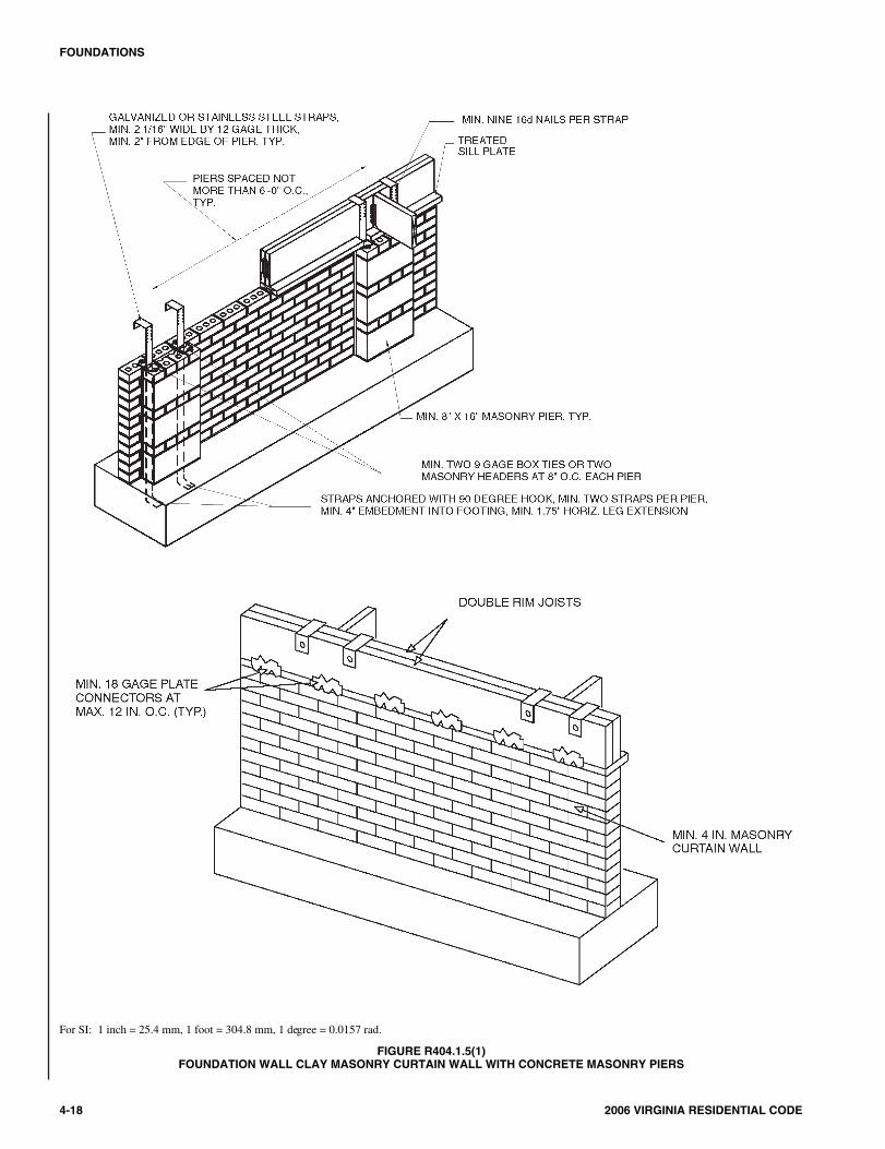
R404.1.5.1 Pier and curtain wall foundations. Use ofpier and curtain wall foundations shall be permitted tosupport light-frame construction not more than two storiesin height, provided the following requirements are met:
1. All load-bearing walls shall be placed on continu-ous concrete footings placed integrally with theexterior wall footings.
2. The minimum actual thickness of a load-bearingmasonry wall shall be not less than 4 inches (102mm) nominal or 33/8 inches (92 mm) actual thick-ness, and shall be bonded integrally with piersspaced in accordance with Section R606.9.
3. Piers shall be constructed in accordance with SectionR606.6 and Section R606.6.1, and shall be bondedinto the load-bearing masonry wall in accordancewith Section R608.1.1 or Section R608.1.1.2.
4. The maximum height of a 4-inch (102 mm)load-bearing masonry foundation wall supportingwood-frame walls and floors shall not be morethan 4 feet (1219 mm).
5. Anchorage shall be in accordance with SectionR403.1.6, Figure R404.1.5(1), or as specified byengineered design accepted by the building official.
6. The unbalanced fill for 4-inch (102 mm) founda-tion walls shall not exceed 24 inches (610 mm) forsolid masonry or 12 inches (305 mm) for hollowmasonry.
7. In Seismic Design Categories D0, D1 and D2, pre-scriptive reinforcement shall be provided in the hor-izontal and vertical direction. Provide minimumhorizontal joint reinforcement of two No.9 gagewires spaced not less than 6 inches (152 mm) or one1/4 inch (6.4 mm) diameter wire at 10 inches (254mm) on center vertically. Provide minimum verti-cal reinforcement of one No. 4 bar at 48 inches(1220 mm) on center horizontally grouted in place.
R404.1.6 Height above finished grade. Concrete andmasonry foundation walls shall extend above the finishedgrade adjacent to the foundation at all points a minimum of4 inches (102 mm) where masonry veneer is used and a min-imum of 6 inches (152 mm) elsewhere.
R404.1.7 Backfill placement. Backfill shall not be placedagainst the wall until the wall has sufficient strength and hasbeen anchored to the floor above, or has been sufficientlybraced to prevent damage by the backfill.
Exception: Bracing is not required for walls supportingless than 4 feet (1219 mm) of unbalanced backfill.
2006 VIRGINIA RESIDENTIAL CODE 4-17
FOUNDATIONS
TABLE R404.1.1(5)—continuedCONCRETE FOUNDATION WALLSh, I, j, k
h. A plain concrete wall with a minimum thickness of 11.5 inches is permitted, provided minimum specified compressive strength of concrete, ′fc , is 3,500 psi.i. Concrete shall have a specified compressive strength of not less than 2,500 psi at 28 days, unless a higher strength is required by note g or h.j. “DR” means design is required in accordance with ACI 318 or ACI 332.k. “PC” means plain concrete.l. Where vertical reinforcement is required, horizontal reinforcement shall be provided in accordance with the requirements of Section R404.4.6.2 for ICF founda-
tion walls.
1704_Va_Res_2006.psM:\data\CODES\STATE CODES\Virginia\2006\Residential Code\Final VP\04_Va_Res_2006.vpThursday, April 10, 2008 11:08:33 AM
Color profile: Generic CMYK printer profileComposite Default screen
4-18 2006 VIRGINIA RESIDENTIAL CODE
FOUNDATIONS
For SI: 1 inch = 25.4 mm, 1 foot = 304.8 mm, 1 degree = 0.0157 rad.
FIGURE R404.1.5(1)FOUNDATION WALL CLAY MASONRY CURTAIN WALL WITH CONCRETE MASONRY PIERS
1804_Va_Res_2006.psM:\data\CODES\STATE CODES\Virginia\2006\Residential Code\Final VP\04_Va_Res_2006.vpThursday, April 10, 2008 11:08:34 AM
Color profile: Generic CMYK printer profileComposite Default screen
R404.1.8 Rubble stone masonry. Rubble stone masonryfoundation walls shall have a minimum thickness of 16inches (406 mm), shall not support an unbalanced backfillexceeding 8 feet (2438 mm) in height, shall not support asoil pressure greater than 30 pounds per square foot per foot(4.71 kPa/m), and shall not be constructed in SeismicDesign Categories D0, D1, D2 or townhouses in SeismicDesign Category C, as established in Figure R301.2(2).
R404.2 Wood foundation walls. Wood foundation walls shallbe constructed in accordance with the provisions of SectionsR404.2.1 through R404.2.6 and with the details shown in Fig-ures R403.1(2) and R403.1(3).
R404.2.1 Identification. All load-bearing lumber shall beidentified by the grade mark of a lumber grading or inspectionagency which has been approved by an accreditation body thatcomplies with DOC PS 20. In lieu of a grade mark, a certificateof inspection issued by a lumber grading or inspection agencymeeting the requirements of this section shall be accepted.
Wood structural panels shall conform to DOC PS 1 or DOC PS2 and shall be identified by a grade mark or certificate ofinspection issued by an approved agency.
R404.2.2 Stud size. The studs used in foundation wallsshall be 2-inch by 6-inch (51 mm by 152 mm) members.When spaced 16 inches (406 mm) on center, a wood specieswith an Fb value of not less than 1,250 pounds per squareinch (8612 kPa) as listed in AF&PA/NDS shall be used.When spaced 12 inches (305 mm) on center, an Fb of not lessthan 875 psi (6029 kPa) shall be required.
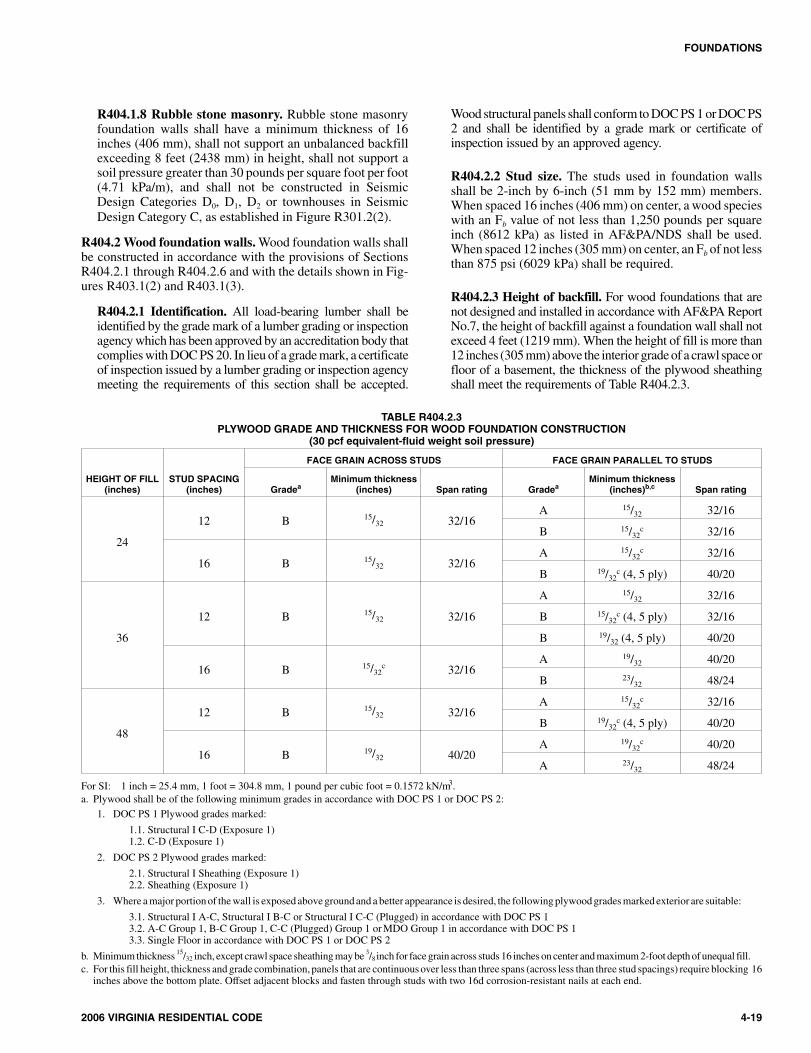
R404.2.3 Height of backfill. For wood foundations that arenot designed and installed in accordance with AF&PA ReportNo.7, the height of backfill against a foundation wall shall notexceed 4 feet (1219 mm). When the height of fill is more than12 inches (305 mm) above the interior grade of a crawl space orfloor of a basement, the thickness of the plywood sheathingshall meet the requirements of Table R404.2.3.
2006 VIRGINIA RESIDENTIAL CODE 4-19
FOUNDATIONS
TABLE R404.2.3PLYWOOD GRADE AND THICKNESS FOR WOOD FOUNDATION CONSTRUCTION
(30 pcf equivalent-fluid weight soil pressure)
HEIGHT OF FILL(inches)
STUD SPACING(inches)
FACE GRAIN ACROSS STUDS FACE GRAIN PARALLEL TO STUDS
GradeaMinimum thickness
(inches) Span rating GradeaMinimum thickness
(inches)b,c Span rating
24
12 B 15/32 32/16A 15/32 32/16
B 15/32c 32/16
16 B 15/32 32/16A 15/32
c 32/16
B 19/32c (4, 5 ply) 40/20
36
12 B 15/32 32/16
A 15/32 32/16
B 15/32c (4, 5 ply) 32/16
B 19/32 (4, 5 ply) 40/20
16 B 15/32c 32/16
A 19/32 40/20
B 23/32 48/24
48
12 B 15/32 32/16A 15/32
c 32/16
B 19/32c (4, 5 ply) 40/20
16 B 19/32 40/20A 19/32
c 40/20
A 23/32 48/24
For SI: 1 inch = 25.4 mm, 1 foot = 304.8 mm, 1 pound per cubic foot = 0.1572 kN/m3.a. Plywood shall be of the following minimum grades in accordance with DOC PS 1 or DOC PS 2:
1. DOC PS 1 Plywood grades marked:
1.1. Structural I C-D (Exposure 1)1.2. C-D (Exposure 1)
2. DOC PS 2 Plywood grades marked:
2.1. Structural I Sheathing (Exposure 1)2.2. Sheathing (Exposure 1)
3. Where a major portion of the wall is exposed above ground and a better appearance is desired, the following plywood grades marked exterior are suitable:
3.1. Structural I A-C, Structural I B-C or Structural I C-C (Plugged) in accordance with DOC PS 13.2. A-C Group 1, B-C Group 1, C-C (Plugged) Group 1 or MDO Group 1 in accordance with DOC PS 13.3. Single Floor in accordance with DOC PS 1 or DOC PS 2
b. Minimum thickness 15/32 inch, except crawl space sheathing may be 3/8 inch for face grain across studs 16 inches on center and maximum 2-foot depth of unequal fill.c. For this fill height, thickness and grade combination, panels that are continuous over less than three spans (across less than three stud spacings) require blocking 16
inches above the bottom plate. Offset adjacent blocks and fasten through studs with two 16d corrosion-resistant nails at each end.
1904_Va_Res_2006.psM:\data\CODES\STATE CODES\Virginia\2006\Residential Code\Final VP\04_Va_Res_2006.vpThursday, April 10, 2008 11:08:34 AM
Color profile: Generic CMYK printer profileComposite Default screen
R404.2.4 Backfilling. Wood foundation walls shall not bebackfilled until the basement floor and first floor have beenconstructed or the walls have been braced. For crawl spaceconstruction, backfill or bracing shall be installed on theinterior of the walls prior to placing backfill on the exterior.
R404.2.5 Drainage and dampproofing. Wood foundationbasements shall be drained and dampproofed in accordancewith Sections R405 and R406, respectively.
R404.2.6 Fastening. Wood structural panel foundationwall sheathing shall be attached to framing in accordancewith Table R602.3(1) and Section R402.1.1.
R404.3 Wood sill plates. Wood sill plates shall be a minimumof 2-inch by 4-inch (51 mm by 102 mm) nominal lumber. Sillplate anchorage shall be in accordance with Sections R403.1.6and R602.11.
R404.4 Insulating concrete form foundation walls. Insulat-ing concrete form (ICF) foundation walls shall be designed andconstructed in accordance with the provisions of this section orin accordance with the provisions of ACI 318. When ACI 318or the provisions of this section are used to design insulatingconcrete form foundation walls, project drawings, typicaldetails and specifications are not required to bear the seal of thearchitect or engineer responsible for design unless otherwiserequired by the state law of the jurisdiction having authority.
R404.4.1 Applicability limits. The provisions of this sec-tion shall apply to the construction of insulating concreteform foundation walls for buildings not more than 60 feet(18 288 mm) in plan dimensions, and floors not more than32 feet (9754 mm) or roofs not more than 40 feet (12 192mm) in clear span. Buildings shall not exceed two stories inheight above grade with each story not more than 10 feet(3048 mm) high. Foundation walls constructed in accor-dance with the provisions of this section shall be limited tobuildings subjected to a maximum ground snow load of 70psf (3.35 kPa) and located in Seismic Design Category A, Bor C. In Seismic Design Categories D0, D1 and D2, founda-tion walls shall comply with Section R404.1.4. Insulatingconcrete form foundation walls supporting above-gradeconcrete walls shall be reinforced as required for the above-grade wall immediately above or the requirements in TablesR404.4(1), R404.4(2), R404.4(3), R404.4(4) or R404.4(5),whichever is greater.
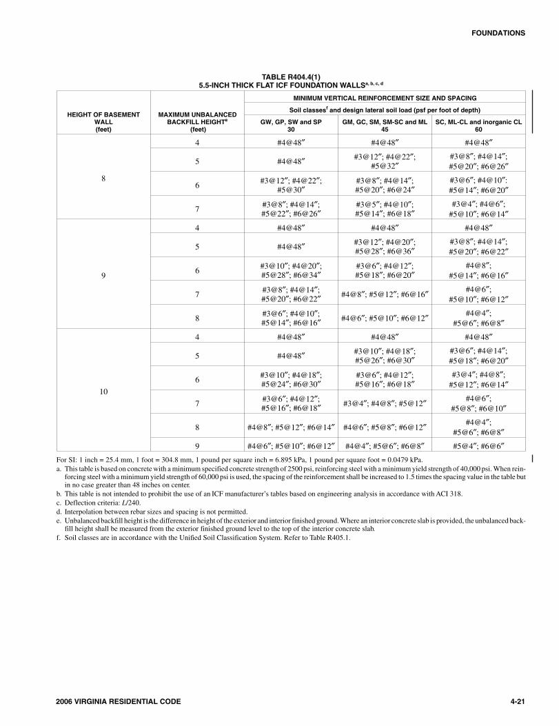
R404.4.2 Flat insulating concrete form wall systems. FlatICF wall systems shall comply with Figure R611.3, shallhave a minimum concrete thickness of 5.5 inches (140 mm),and shall have reinforcement in accordance with TableR404.4(1), R404.4(2) or R404.4(3). Alternatively, for7.5-inch (191 mm) and 9.5-inch (241 mm) flat ICF wall sys-tems, use of Table R404.1.1(5) shall be permitted, providedthe vertical reinforcement is of the grade and located withinthe wall as required by that table.
R404.4.3 Waffle-grid insulating concrete form wall sys-tems. Waffle-grid wall systems shall have a minimum nom-inal concrete thickness of 6 inches (152 mm) for thehorizontal and vertical concrete members (cores) and shallbe reinforced in accordance with Table R404.4(4). The min-
imum core dimension shall comply with Table R611.2 andFigure R611.4.
R404.4.4 Screen-grid insulating concrete form wall sys-tems. Screen-grid ICF wall systems shall have a minimumnominal concrete thickness of 6 inches (152 mm) for thehorizontal and vertical concrete members (cores). The mini-mum core dimensions shall comply with Table R611.2 andFigure R611.5. Walls shall have reinforcement in accor-dance with Table R404.4(5).
R404.4.5 Concrete material. Ready-mixed concrete forinsulating concrete form walls shall be in accordance withSection R402.2. Maximum slump shall not be greater than 6inches (152 mm) as determined in accordance with ASTMC 143. Maximum aggregate size shall not be larger than 3/4
inch (19.1 mm).
Exception: Concrete mixes conforming to the ICF man-ufacturer’s recommendations.
R404.4.6 Reinforcing steel.
R404.4.6.1 General. Reinforcing steel shall meet therequirements of ASTM A 615, A 706 or A 996. The min-imum yield strength of reinforcing steel shall be 40,000psi (Grade 40) (276 MPa). Vertical and horizontal wallreinforcements shall be placed no closer to the outsideface of the wall than one-half the wall thickness. Steelreinforcement for foundation walls shall have concretecover in accordance with ACI 318.
Exception: Where insulated concrete forms are usedand the form remains in place as cover for the con-crete, the minimum concrete cover for the reinforcingsteel is permitted to be reduced to 3/4 inch (19.1 mm).
R404.4.6.2 Horizontal reinforcement. When verticalreinforcement is required, ICF foundation walls shallhave horizontal reinforcement in accordance with thissection. ICF foundation walls up to 8 feet (2438 mm) inheight shall have a minimum of one continuous No. 4horizontal reinforcing bar placed at 48 inches (1219 mm)on center with one bar located within 12 inches (305mm) of the top of the wall story. ICF foundation wallsgreater than 8 feet (2438 mm) in height shall have a mini-mum of one continuous No. 4 horizontal reinforcing barplaced at 36 inches (914 mm) on center with one barlocated within 12 inches (305 mm) of the top of the wallstory.
R404.4.6.3 Wall openings. Vertical wall reinforcementrequired by Section R404.4.2, R404.4.3 or R404.4.4 thatis interrupted by wall openings shall have additional ver-tical reinforcement of the same size placed within 12inches (305 mm) of each side of the opening.
R404.4.7 Foam plastic insulation. Foam plastic insulationin insulating concrete foam construction shall comply withthis section.
R404.4.7.1 Material. Insulating concrete form materialshall meet the surface burning characteristics of SectionR314.3. A thermal barrier shall be provided on the build-ing interior in accordance with Section R314.4.
4-20 2006 VIRGINIA RESIDENTIAL CODE
FOUNDATIONS
2004_Va_Res_2006.psM:\data\CODES\STATE CODES\Virginia\2006\Residential Code\Final VP\04_Va_Res_2006.vpThursday, April 10, 2008 11:08:35 AM
Color profile: Generic CMYK printer profileComposite Default screen
2006 VIRGINIA RESIDENTIAL CODE 4-21
FOUNDATIONS
TABLE R404.4(1)5.5-INCH THICK FLAT ICF FOUNDATION WALLSa, b, c, d
HEIGHT OF BASEMENTWALL(feet)
MAXIMUM UNBALANCEDBACKFILL HEIGHTe
(feet)
MINIMUM VERTICAL REINFORCEMENT SIZE AND SPACING
Soil classesf and design lateral soil load (psf per foot of depth)
GW, GP, SW and SP30
GM, GC, SM, SM-SC and ML45
SC, ML-CL and inorganic CL60
8
4 #4@48″ #4@48″ #4@48″
5 #4@48″ #3@12″; #4@22″;#5@32″
#3@8″; #4@14″;#5@20″; #6@26″
6 #3@12″; #4@22″;#5@30″
#3@8″; #4@14″;#5@20″; #6@24″
#3@6″; #4@10″:#5@14″; #6@20″
7 #3@8″; #4@14″;#5@22″; #6@26″
#3@5″; #4@10″;#5@14″; #6@18″
#3@4″; #4@6″;#5@10″; #6@14″
9
4 #4@48″ #4@48″ #4@48″
5 #4@48″ #3@12″; #4@20″;#5@28″; #6@36″
#3@8″; #4@14″;#5@20″; #6@22″
6 #3@10″; #4@20″;#5@28″; #6@34″
#3@6″; #4@12″;#5@18″; #6@20″
#4@8″;#5@14″; #6@16″
7 #3@8″; #4@14″;#5@20″; #6@22″ #4@8″; #5@12″; #6@16″ #4@6″;
#5@10″; #6@12″
8 #3@6″; #4@10″;#5@14″; #6@16″ #4@6″; #5@10″; #6@12″ #4@4″;
#5@6″; #6@8″
10
4 #4@48″ #4@48″ #4@48″
5 #4@48″ #3@10″; #4@18″;#5@26″; #6@30″
#3@6″; #4@14″;#5@18″; #6@20″
6 #3@10″; #4@18″;#5@24″; #6@30″
#3@6″; #4@12″;#5@16″; #6@18″
#3@4″; #4@8″;#5@12″; #6@14″
7 #3@6″; #4@12″;#5@16″; #6@18″ #3@4″; #4@8″; #5@12″ #4@6″;
#5@8″; #6@10″
8 #4@8″; #5@12″; #6@14″ #4@6″; #5@8″; #6@12″ #4@4″;#5@6″; #6@8″
9 #4@6″; #5@10″; #6@12″ #4@4″; #5@6″; #6@8″ #5@4″; #6@6″For SI: 1 inch = 25.4 mm, 1 foot = 304.8 mm, 1 pound per square inch = 6.895 kPa, 1 pound per square foot = 0.0479 kPa.a. This table is based on concrete with a minimum specified concrete strength of 2500 psi, reinforcing steel with a minimum yield strength of 40,000 psi. When rein-
forcing steel with a minimum yield strength of 60,000 psi is used, the spacing of the reinforcement shall be increased to 1.5 times the spacing value in the table butin no case greater than 48 inches on center.
b. This table is not intended to prohibit the use of an ICF manufacturer’s tables based on engineering analysis in accordance with ACI 318.c. Deflection criteria: L/240.d. Interpolation between rebar sizes and spacing is not permitted.e. Unbalanced backfill height is the difference in height of the exterior and interior finished ground. Where an interior concrete slab is provided, the unbalanced back-
fill height shall be measured from the exterior finished ground level to the top of the interior concrete slab.f. Soil classes are in accordance with the Unified Soil Classification System. Refer to Table R405.1.
2104_Va_Res_2006.psM:\data\CODES\STATE CODES\Virginia\2006\Residential Code\Final VP\04_Va_Res_2006.vpThursday, April 10, 2008 11:08:35 AM
Color profile: Generic CMYK printer profileComposite Default screen
4-22 2006 VIRGINIA RESIDENTIAL CODE
FOUNDATIONS
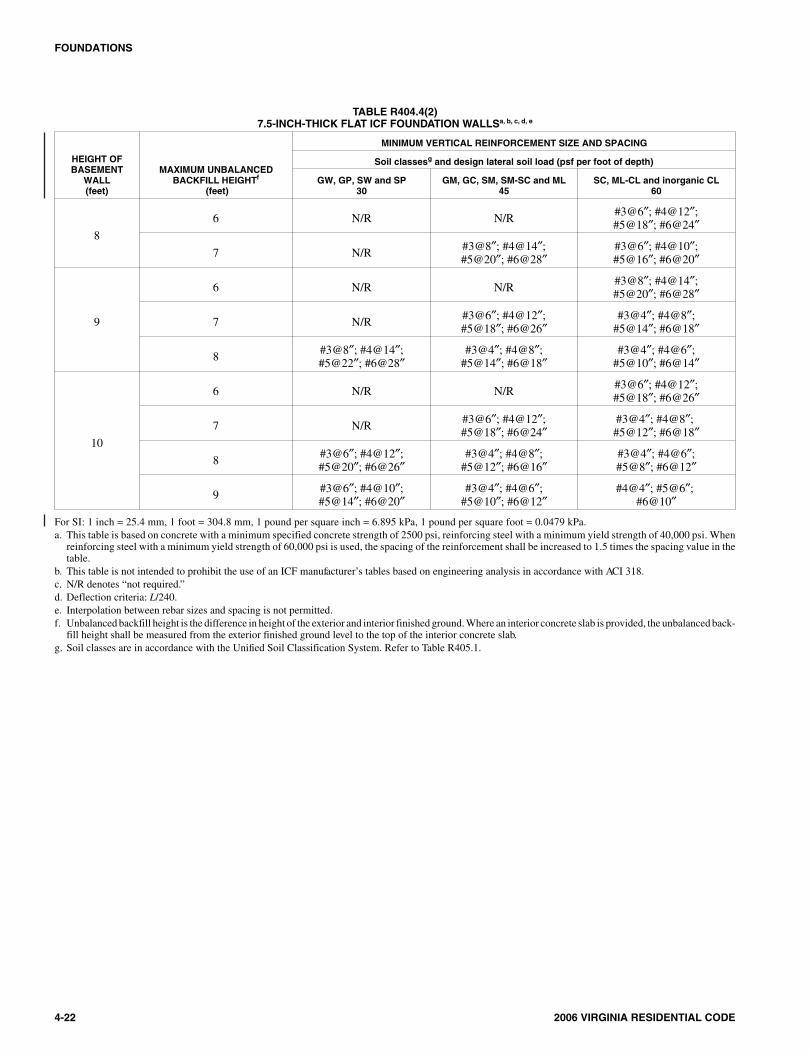
TABLE R404.4(2)7.5-INCH-THICK FLAT ICF FOUNDATION WALLSa, b, c, d, e
HEIGHT OFBASEMENT
WALL(feet)
MAXIMUM UNBALANCEDBACKFILL HEIGHTf
(feet)
MINIMUM VERTICAL REINFORCEMENT SIZE AND SPACING
Soil classesg and design lateral soil load (psf per foot of depth)
GW, GP, SW and SP30
GM, GC, SM, SM-SC and ML45
SC, ML-CL and inorganic CL60
8
6 N/R N/R #3@6″; #4@12″;#5@18″; #6@24″
7 N/R #3@8″; #4@14″;#5@20″; #6@28″
#3@6″; #4@10″;#5@16″; #6@20″
9
6 N/R N/R #3@8″; #4@14″;#5@20″; #6@28″
7 N/R #3@6″; #4@12″;#5@18″; #6@26″
#3@4″; #4@8″;#5@14″; #6@18″
8 #3@8″; #4@14″;#5@22″; #6@28″
#3@4″; #4@8″;#5@14″; #6@18″
#3@4″; #4@6″;#5@10″; #6@14″
10
6 N/R N/R #3@6″; #4@12″;#5@18″; #6@26″
7 N/R #3@6″; #4@12″;#5@18″; #6@24″
#3@4″; #4@8″;#5@12″; #6@18″
8 #3@6″; #4@12″;#5@20″; #6@26″
#3@4″; #4@8″;#5@12″; #6@16″
#3@4″; #4@6″;#5@8″; #6@12″
9 #3@6″; #4@10″;#5@14″; #6@20″
#3@4″; #4@6″;#5@10″; #6@12″
#4@4″; #5@6″;#6@10″
For SI: 1 inch = 25.4 mm, 1 foot = 304.8 mm, 1 pound per square inch = 6.895 kPa, 1 pound per square foot = 0.0479 kPa.a. This table is based on concrete with a minimum specified concrete strength of 2500 psi, reinforcing steel with a minimum yield strength of 40,000 psi. When
reinforcing steel with a minimum yield strength of 60,000 psi is used, the spacing of the reinforcement shall be increased to 1.5 times the spacing value in thetable.
b. This table is not intended to prohibit the use of an ICF manufacturer’s tables based on engineering analysis in accordance with ACI 318.c. N/R denotes “not required.”d. Deflection criteria: L/240.e. Interpolation between rebar sizes and spacing is not permitted.f. Unbalanced backfill height is the difference in height of the exterior and interior finished ground. Where an interior concrete slab is provided, the unbalanced back-
fill height shall be measured from the exterior finished ground level to the top of the interior concrete slab.g. Soil classes are in accordance with the Unified Soil Classification System. Refer to Table R405.1.
2204_Va_Res_2006.psM:\data\CODES\STATE CODES\Virginia\2006\Residential Code\Final VP\04_Va_Res_2006.vpThursday, April 10, 2008 11:08:35 AM
Color profile: Generic CMYK printer profileComposite Default screen
2006 VIRGINIA RESIDENTIAL CODE 4-23
FOUNDATIONS
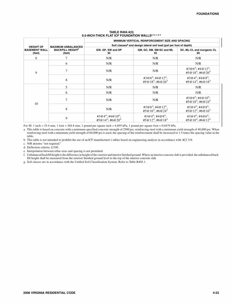
TABLE R404.4(3)9.5-INCH-THICK FLAT ICF FOUNDATION WALLSa, b, c, d, e
HEIGHT OFBASEMENT WALL
(feet)
MAXIMUM UNBALANCEDBACKFILL HEIGHTf
(feet)
MINIMUM VERTICAL REINFORCEMENT SIZE AND SPACING
Soil classesg and design lateral soil load (psf per foot of depth)
GW, GP, SW and SP30
GM, GC, SM, SM-SC and ML45
SC, ML-CL and inorganic CL60
8 7 N/R N/R N/R
9
6 N/R N/R N/R
7 N/R N/R #3@6″; #4@12″;#5@18″; #6@26″
8 N/R #3@6″; #4@12″;#5@18″; #6@26″
#3@4″; #4@8″;#5@14″; #6@18″
10
5 N/R N/R N/R
6 N/R N/R N/R
7 N/R N/R #3@6″; #4@10″;#5@18″; #6@24″
8 N/R #3@6″; #4@12″;#5@16″; #6@24″
#3@4″; #4@8″;#5@12″; #6@16″
9 #3@4″; #4@10″;#5@14″; #6@20″
#3@4″; #4@8″;#5@12″; #6@18″
#3@4″; #4@6″;#5@10″; #6@12″
For SI: 1 inch = 25.4 mm, 1 foot = 304.8 mm, 1 pound per square inch = 6.895 kPa, 1 pound per square foot = 0.0479 kPa.a. This table is based on concrete with a minimum specified concrete strength of 2500 psi, reinforcing steel with a minimum yield strength of 40,000 psi. When
reinforcing steel with a minimum yield strength of 60,000 psi is used, the spacing of the reinforcement shall be increased to 1.5 times the spacing value in thetable.
b. This table is not intended to prohibit the use of an ICF manufacturer’s tables based on engineering analysis in accordance with ACI 318.c. N/R denotes “not required.”d. Deflection criteria: L/240.e. Interpolation between rebar sizes and spacing is not permitted.f. Unbalanced backfill height is the difference in height of the exterior and interior finished ground. Where an interior concrete slab is provided, the unbalanced back-
fill height shall be measured from the exterior finished ground level to the top of the interior concrete slab.g. Soil classes are in accordance with the Unified Soil Classification System. Refer to Table R405.1.
2304_Va_Res_2006.psM:\data\CODES\STATE CODES\Virginia\2006\Residential Code\Final VP\04_Va_Res_2006.vpThursday, April 10, 2008 11:08:35 AM
Color profile: Generic CMYK printer profileComposite Default screen
4-24 2006 VIRGINIA RESIDENTIAL CODE
FOUNDATIONS
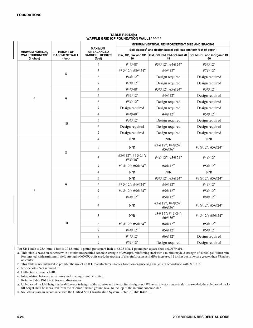
TABLE R404.4(4)WAFFLE GRID ICF FOUNDATION WALLSa, b, c, d, e
MINIMUM NOMINALWALL THICKNESSf
(inches)
HEIGHT OFBASEMENT WALL
(feet)
MAXIMUMUNBALANCED
BACKFILL HEIGHTg
(feet)
MINIMUM VERTICAL REINFORCEMENT SIZE AND SPACING
Soil classesh and design lateral soil load (psf per foot of depth)
GW, GP, SW and SP30
GM, GC, SM, SM-SC and ML45
SC, ML-CL and inorganic CL60
6
8
4 #4@48″ #3@12″; #4@24″ #3@12″
5 #3@12″; #5@24″ #4@12″ #7@12″
6 #4@12″ Design required Design required
7 #7@12″ Design required Design required
9
4 #4@48″ #3@12″; #5@24″ #3@12″
5 #3@12″ #4@12″ Design required
6 #5@12″ Design required Design required
7 Design required Design required Design required
10
4 #4@48″ #4@12″ #5@12″
5 #3@12″ Design required Design required
6 Design required Design required Design required
7 Design required Design required Design required
8
8
4 N/R N/R N/R
5 N/R #3@12″; #4@24″;#5@36″ #3@12″; #5@24″
6 #3@12″; #4@24″;#5@36″ #4@12″; #5@24″ #4@12″
7 #3@12″; #6@24″ #4@12″ #5@12″
9
4 N/R N/R N/R
5 N/R #3@12″; #5@24″ #3@12″; #5@24″
6 #3@12″; #4@24″ #4@12″ #4@12″
7 #4@12″; #5@24″ #5@12″ #5@12″
8 #4@12″ #5@12″ #8@12″
10
4 N/R #3@12″; #4@24″;#6@36″ #3@12″; #5@24″
5 N/R #3@12″; #4@24″;#6@36″ #4@12″; #5@24″
6 #3@12″; #5@24″ #4@12″ #5@12″
7 #4@12″ #5@12″ #6@12″
8 #4@12″ #6@12″ Design required
9 #5@12″ Design required Design required
For SI: 1 inch = 25.4 mm, 1 foot = 304.8 mm, 1 pound per square inch = 6.895 kPa, 1 pound per square foot = 0.0479 kPa.a. This table is based on concrete with a minimum specified concrete strength of 2500 psi, reinforcing steel with a minimum yield strength of 40,000 psi. When rein-
forcing steel with a minimum yield strength of 60,000 psi is used, the spacing of the reinforcement shall be increased 12 inches but in no case greater than 48 incheson center.
b. This table is not intended to prohibit the use of an ICF manufacturer’s tables based on engineering analysis in accordance with ACI 318.c. N/R denotes “not required.”d. Deflection criteria: L/240.e. Interpolation between rebar sizes and spacing is not permitted.f. Refer to Table R611.4(2) for wall dimensions.g. Unbalanced backfill height is the difference in height of the exterior and interior finished ground. Where an interior concrete slab is provided, the unbalanced back-
fill height shall be measured from the exterior finished ground level to the top of the interior concrete slab.h. Soil classes are in accordance with the Unified Soil Classification System. Refer to Table R405.1.
2404_Va_Res_2006.psM:\data\CODES\STATE CODES\Virginia\2006\Residential Code\Final VP\04_Va_Res_2006.vpThursday, April 10, 2008 11:08:35 AM
Color profile: Generic CMYK printer profileComposite Default screen
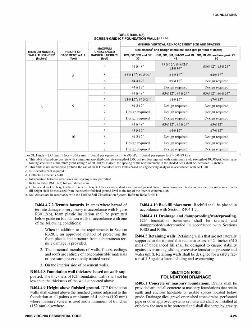
R404.4.7.2 Termite hazards. In areas where hazard oftermite damage is very heavy in accordance with FigureR301.2(6), foam plastic insulation shall be permittedbelow grade on foundation walls in accordance with oneof the following conditions:
1. When in addition to the requirements in SectionR320.1, an approved method of protecting thefoam plastic and structure from subterranean ter-mite damage is provided.
2. The structural members of walls, floors, ceilingsand roofs are entirely of noncombustible materialsor pressure preservatively treated wood.
3. On the interior side of basement walls.
R404.4.8 Foundation wall thickness based on walls sup-ported. The thickness of ICF foundation walls shall not beless than the thickness of the wall supported above.
R404.4.9 Height above finished ground. ICF foundationwalls shall extend above the finished ground adjacent to thefoundation at all points a minimum of 4 inches (102 mm)where masonry veneer is used and a minimum of 6 inches(152 mm) elsewhere.
R404.4.10 Backfill placement. Backfill shall be placed inaccordance with Section R404.1.7.
R404.4.11 Drainage and dampproofing/waterproofing.ICF foundation basements shall be drained anddampproofed/waterproofed in accordance with SectionsR405 and R406.
R404.5 Retaining walls. Retaining walls that are not laterallysupported at the top and that retain in excess of 24 inches (610mm) of unbalanced fill shall be designed to ensure stabilityagainst overturning, sliding, excessive foundation pressure andwater uplift. Retaining walls shall be designed for a safety fac-tor of 1.5 against lateral sliding and overturning.
SECTION R405FOUNDATION DRAINAGE
R405.1 Concrete or masonry foundations. Drains shall beprovided around all concrete or masonry foundations that retainearth and enclose habitable or usable spaces located belowgrade. Drainage tiles, gravel or crushed stone drains, perforatedpipe or other approved systems or materials shall be installed ator below the area to be protected and shall discharge by gravity
2006 VIRGINIA RESIDENTIAL CODE 4-25
FOUNDATIONS
TABLE R404.4(5)SCREEN-GRID ICF FOUNDATION WALLSa, b c, d, e
MINIMUM NOMINALWALL THICKNESSf
(inches)
HEIGHT OFBASEMENT WALL
(feet)
MAXIMUMUNBALANCED
BACKFILL HEIGHTg
(feet)
MINIMUM VERTICAL REINFORCEMENT SIZE AND SPACING
Soil classesh and design lateral soil load (psf per foot of depth)
GW, GP, SW and SP30
GM, GC, SM, SM-SC and ML45
SC, ML-CL and inorganic CL60
6
8
4 #4@48″ #3@12″; #4@24″;#5@36″ #3@12″; #5@24″
5 #3@12″; #4@24″ #3@12″ #4@12″
6 #4@12″ #5@12″ Design required
7 #4@12″ Design required Design required
9
4 #4@48″ #3@12″; #4@24″ #3@12″; #6@24″
5 #3@12″; #5@24″ #4@12″ #7@12″
6 #4@12″ Design required Design required
7 Design required Design required Design required
8 Design required Design required Design required
10
4 #4@48″ #3@12″; #5@24″ #3@12″
5 #3@12″ #4@12″ #7@12″
6 #4@12″ Design required Design required
7 Design required Design required Design required
8 Design required Design required Design required
For SI: 1 inch = 25.4 mm, 1 foot = 304.8 mm, 1 pound per square inch = 6.895 kPa, 1 pound per square foot = 0.0479 kPa.a. This table is based on concrete with a minimum specified concrete strength of 2500 psi, reinforcing steel with a minimum yield strength of 40,000 psi. When rein-
forcing steel with a minimum yield strength of 60,000 psi is used, the spacing of the reinforcement in the shaded cells shall be increased 12 inches.b. This table is not intended to prohibit the use of an ICF manufacturer’s tables based on engineering analysis in accordance with ACI 318.c. N/R denotes “not required.”d. Deflection criteria: L/240.e. Interpolation between rebar sizes and spacing is not permitted.f. Refer to Table R611.4(2) for wall dimensions.g. Unbalanced backfill height is the difference in height of the exterior and interior finished ground. Where an interior concrete slab is provided, the unbalanced back-
fill height shall be measured from the exterior finished ground level to the top of the interior concrete slab.h. Soil classes are in accordance with the Unified Soil Classification System. Refer to Table R405.1.
2504_Va_Res_2006.psM:\data\CODES\STATE CODES\Virginia\2006\Residential Code\Final VP\04_Va_Res_2006.vpThursday, April 10, 2008 11:08:36 AM
Color profile: Generic CMYK printer profileComposite Default screen
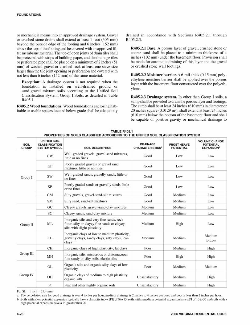
or mechanical means into an approved drainage system. Gravelor crushed stone drains shall extend at least 1 foot (305 mm)beyond the outside edge of the footing and 6 inches (152 mm)above the top of the footing and be covered with an approved fil-ter membrane material. The top of open joints of drain tiles shallbe protected with strips of building paper, and the drainage tilesor perforated pipe shall be placed on a minimum of 2 inches (51mm) of washed gravel or crushed rock at least one sieve sizelarger than the tile joint opening or perforation and covered withnot less than 6 inches (152 mm) of the same material.
Exception: A drainage system is not required when thefoundation is installed on well-drained ground orsand-gravel mixture soils according to the Unified SoilClassification System, Group I Soils, as detailed in TableR405.1.
R405.2 Wood foundations. Wood foundations enclosing hab-itable or usable spaces located below grade shall be adequately
drained in accordance with Sections R405.2.1 throughR405.2.3.
R405.2.1 Base. A porous layer of gravel, crushed stone orcoarse sand shall be placed to a minimum thickness of 4inches (102 mm) under the basement floor. Provision shallbe made for automatic draining of this layer and the gravelor crushed stone wall footings.
R405.2.2 Moisture barrier. A 6-mil-thick (0.15 mm) poly-ethylene moisture barrier shall be applied over the porouslayer with the basement floor constructed over the polyeth-ylene.
R405.2.3 Drainage system. In other than Group I soils, asump shall be provided to drain the porous layer and footings.The sump shall be at least 24 inches (610 mm) in diameter or20 inches square (0.0129 m2), shall extend at least 24 inches(610 mm) below the bottom of the basement floor and shallbe capable of positive gravity or mechanical drainage to
4-26 2006 VIRGINIA RESIDENTIAL CODE
FOUNDATIONS
TABLE R405.1PROPERTIES OF SOILS CLASSIFIED ACCORDING TO THE UNIFIED SOIL CLASSIFICATION SYSTEM
SOILGROUP
UNIFIED SOILCLASSIFICATIONSYSTEM SYMBOL SOIL DESCRIPTION
DRAINAGECHARACTERISTICSa
FROST HEAVEPOTENTIAL
VOLUME CHANGEPOTENTIAL
EXPANSIONb
Group I
GW Well-graded gravels, gravel sand mixtures,little or no fines Good Low Low
GP Poorly graded gravels or gravel sandmixtures, little or no fines Good Low Low
SW Well-graded sands, gravelly sands, little orno fines Good Low Low
SP Poorly graded sands or gravelly sands, littleor no fines Good Low Low
GM Silty gravels, gravel-sand-silt mixtures Good Medium Low
SM Silty sand, sand-silt mixtures Good Medium Low
Group II
GC Clayey gravels, gravel-sand-clay mixtures Medium Medium Low
SC Clayey sands, sand-clay mixture Medium Medium Low
MLInorganic silts and very fine sands, rockflour, silty or clayey fine sands or clayeysilts with slight plasticity
Medium High Low
CLInorganic clays of low to medium plasticity,gravelly clays, sandy clays, silty clays, leanclays
Medium MediumMediumto Low
Group IIICH Inorganic clays of high plasticity, fat clays Poor Medium High
MH Inorganic silts, micaceous or diatomaceousfine sandy or silty soils, elastic silts Poor High High
Group IV
OL Organic silts and organic silty clays of lowplasticity Poor Medium Medium
OH Organic clays of medium to high plasticity,organic silts Unsatisfactory Medium High
Pt Peat and other highly organic soils Unsatisfactory Medium High
For SI: 1 inch = 25.4 mm.a. The percolation rate for good drainage is over 4 inches per hour, medium drainage is 2 inches to 4 inches per hour, and poor is less than 2 inches per hour.b. Soils with a low potential expansion typically have a plasticity index (PI) of 0 to 15, soils with a medium potential expansion have a PI of 10 to 35 and soils with a
high potential expansion have a PI greater than 20.
2604_Va_Res_2006.psM:\data\CODES\STATE CODES\Virginia\2006\Residential Code\Final VP\04_Va_Res_2006.vpThursday, April 10, 2008 11:08:36 AM
Color profile: Generic CMYK printer profileComposite Default screen
remove any accumulated water. The drainage system shalldischarge into an approved sewer system or to daylight.
SECTION R406FOUNDATION WATERPROOFING
AND DAMPPROOFINGR406.1 Concrete and masonry foundation dampproofing.Except where required by Section R406.2 to be waterproofed,foundation walls that retain earth and enclose interior spacesand floors below grade shall be dampproofed from the top ofthe footing to the finished grade. Masonry walls shall have notless than 3/8 inch (9.5 mm) portland cement parging applied tothe exterior of the wall. The parging shall be dampproofed inaccordance with one of the following:
1. Bituminous coating.
2. 3 pounds per square yard (1.63 kg/m2) of acrylic modi-fied cement.
3. 1/8-inch (3.2 mm) coat of surface-bonding cement com-plying with ASTM C 887.
4. Any material permitted for waterproofing in SectionR406.2.
5. Other approved methods or materials.
Exception: Parging of unit masonry walls is notrequired where a material is approved for direct appli-cation to the masonry.
Concrete walls shall be dampproofed by applying any one ofthe above listed dampproofing materials or any one of thewaterproofing materials listed in Section R406.2 to the exteriorof the wall.
R406.2 Concrete and masonry foundation waterproofing.In areas where a high water table or other severe soil-water con-ditions are known to exist, exterior foundation walls that retainearth and enclose interior spaces and floors below grade shallbe waterproofed from the top of the footing to the finishedgrade. Walls shall be waterproofed in accordance with one ofthe following:
1. 2-ply hot-mopped felts.
2. 55 pound (25 kg) roll roofing.
3. 6-mil (0.15 mm) polyvinyl chloride.
4. 6-mil (0.15 mm) polyethylene.
5. 40-mil (1 mm) polymer-modified asphalt.
6. 60-mil (1.5 mm) flexible polymer cement.
7. 1/8 inch (3 mm) cement-based, fiber-reinforced, water-proof coating.
8. 60-mil (0.22 mm) solvent-free liquid-applied syntheticrubber.
Exception: Organic-solvent-based products such as hydro-carbons, chlorinated hydrocarbons, ketones and esters shallnot be used for ICF walls with expanded polystyrene formmaterial. Use of plastic roofing cements, acrylic coatings,latex coatings, mortars and pargings to seal ICF walls is
permitted. Cold-setting asphalt or hot asphalt shall conformto type C of ASTM D 449. Hot asphalt shall be applied at atemperature of less than 200°F (93°C).
All joints in membrane waterproofing shall be lapped andsealed with an adhesive compatible with the membrane.
R406.3 Dampproofing for wood foundations. Wood founda-tions enclosing habitable or usable spaces located below gradeshall be dampproofed in accordance with Sections R406.3.1through R406.3.4.
R406.3.1 Panel joint sealed. Plywood panel joints in thefoundation walls shall be sealed full length with a caulkingcompound capable of producing a moisture-proof sealunder the conditions of temperature and moisture content atwhich it will be applied and used.
R406.3.2 Below-grade moisture barrier. A 6-mil-thick(0.15 mm) polyethylene film shall be applied over thebelow-grade portion of exterior foundation walls prior tobackfilling. Joints in the polyethylene film shall be lapped 6inches (152 mm) and sealed with adhesive. The top edge ofthe polyethylene film shall be bonded to the sheathing toform a seal. Film areas at grade level shall be protected frommechanical damage and exposure by a pressurepreservatively treated lumber or plywood strip attached tothe wall several inches above finish grade level and extend-ing approximately 9 inches (229 mm) below grade. Thejoint between the strip and the wall shall be caulked fulllength prior to fastening the strip to the wall. Other cover-ings appropriate to the architectural treatment may also beused. The polyethylene film shall extend down to the bot-tom of the wood footing plate but shall not overlap or extendinto the gravel or crushed stone footing.
R406.3.3 Porous fill. The space between the excavation andthe foundation wall shall be backfilled with the same mate-rial used for footings, up to a height of 1 foot (305 mm)above the footing for well-drained sites, or one-half the totalback-fill height for poorly drained sites. The porous fill shallbe covered with strips of 30-pound (13.6 kg) asphalt paperor 6-mil (0.15 mm) polyethylene to permit water seepagewhile avoiding infiltration of fine soils.
R406.3.4 Backfill. The remainder of the excavated areashall be backfilled with the same type of soil as was removedduring the excavation.
SECTION R407COLUMNS
R407.1 Wood column protection. Wood columns shall beprotected against decay as set forth in Section R319.
R407.2 Steel column protection. All surfaces (inside and out-side) of steel columns shall be given a shop coat ofrust-inhibitive paint, except for corrosion-resistant steel andsteel treated with coatings to provide corrosion resistance.
R407.3 Structural requirements. The columns shall berestrained to prevent lateral displacement at the bottom end.Wood columns shall not be less in nominal size than 4 inches by
2006 VIRGINIA RESIDENTIAL CODE 4-27
FOUNDATIONS
2704_Va_Res_2006.psM:\data\CODES\STATE CODES\Virginia\2006\Residential Code\Final VP\04_Va_Res_2006.vpThursday, April 10, 2008 11:08:36 AM
Color profile: Generic CMYK printer profileComposite Default screen
4 inches (102 mm by 102 mm) and steel columns shall not beless than 3-inch-diameter (76 mm) standard pipe or approvedequivalent.
Exception: In Seismic Design Categories A, B and C col-umns no more than 48 inches (1219 mm) in height on a pieror footing are exempt from the bottom end lateral displace-ment requirement within underfloor areas enclosed by acontinuous foundation.
SECTION R408UNDER-FLOOR SPACE
R408.1 Ventilation. The under-floor space between the bot-tom of the floor joists and the earth under any building (exceptspace occupied by a basement) shall have ventilation openingsthrough foundation walls or exterior walls. The minimum netarea of ventilation openings shall not be less than 1 square foot(0.0929 m2) for each 150 square feet (14 m2) of under-floorspace area. One such ventilating opening shall be within 3 feet(914 mm) of each corner of the building.
Exception: When the exposed earth is covered with a con-tinuous vapor barrier, the minimum net area of ventilationopenings shall be not less than 1 square foot (0.0929 m2) foreach 1500 square feet (139 m2) of under-floor space area.Joints of the vapor retarder shall overlap by 6 inches (152mm).
R408.2 Openings for under-floor ventilation. Ventilationopenings shall be covered for their height and width with any ofthe following materials provided that the least dimension of thecovering shall not exceed 1/4 inch (6.4 mm):
1. Perforated sheet metal plates not less than 0.070 inch(1.8 mm) thick.
2. Expanded sheet metal plates not less than 0.047 inch (1.2mm) thick.
3. Cast-iron grill or grating.
4. Extruded load-bearing brick vents.
5. Hardware cloth of 0.035 inch (0.89 mm) wire or heavier.
6. Corrosion-resistant wire mesh, with the least dimensionbeing 1/8 inch (3.2 mm).
R408.3 Unvented crawl space. Ventilation openings inunder-floor spaces specified in Sections R408.1 and R408.2shall not be required where:
1. Exposed earth is covered with a continuous vaporretarder. Joints of the vapor retarder shall overlap by 6inches (152 mm) and shall be sealed or taped. The edgesof the vapor retarder shall extend at least 6 inches (152mm) up the stem wall and shall be attached and sealed tothe stem wall; and
2. One of the following is provided for the under-floorspace:
2.1. Continuously operated mechanical exhaust ven-tilation at a rate equal to 1 cfm (0.47 L/s) for each50 ft2 (4.7 m2) of crawlspace floor area, includingan air pathway to the common area (such as a
duct or transfer grille), and perimeter walls insu-lated in accordance with Section N1102.2.8;
2.2. Conditioned air supply sized to deliver at a rateequal to 1 cfm (0.47 L/s) for each 50 ft2 (4.7 m2)of under-floor area, including a return air path-way to the common area (such as a duct or trans-fer grille), and perimeter walls insulated inaccordance with Section N1102.2.8;
2.3. Plenum complying with Section M1601.4, ifunder-floor space is used as a plenum.
R408.4 Access. Access shall be provided to all under-floorspaces. Access openings through the floor shall be a minimumof 18 inches by 24 inches (457 mm by 610 mm). Openingsthrough a perimeter wall shall be not less than 16 inches by 24inches (407 mm by 610 mm). When any portion of thethrough-wall access is below grade, an areaway not less than 16inches by 24 inches (407 mm by 610 mm) shall be provided.The bottom of the areaway shall be below the threshold of theaccess opening. Through wall access openings shall not belocated under a door to the residence. See Section M1305.1.4for access requirements where mechanical equipment islocated under floors.
R408.5 Removal of debris. The under-floor grade shall becleaned of all vegetation and organic material. All wood formsused for placing concrete shall be removed before a building isoccupied or used for any purpose. All construction materialsshall be removed before a building is occupied or used for anypurpose.
R408.6 Finished grade. The finished grade of under-floor sur-face may be located at the bottom of the footings; however,where there is evidence that the groundwater table can rise towithin 6 inches (152 mm) of the finished floor at the buildingperimeter or where there is evidence that the surface water doesnot readily drain from the building site, the grade in theunder-floor space shall be as high as the outside finished grade,unless an approved drainage system is provided.
R408.7 Flood resistance. For buildings located in areas proneto flooding as established in Table R301.2(1):
1. Walls enclosing the under-floor space shall be providedwith flood openings in accordance with SectionR324.2.2.
2. The finished ground level of the under-floor space shallbe equal to or higher than the outside finished groundlevel.
Exception: Under-floor spaces that meet the require-ments of FEMA/FIA TB 11-1.
4-28 2006 VIRGINIA RESIDENTIAL CODE
FOUNDATIONS
➡
2804_Va_Res_2006.psM:\data\CODES\STATE CODES\Virginia\2006\Residential Code\Final VP\04_Va_Res_2006.vpThursday, April 10, 2008 11:08:36 AM
Color profile: Generic CMYK printer profileComposite Default screen