Embed Size (px)
Citation preview
Chapter 4. Accessible Routes
401 General 401.1 Scope. Accessible routes required by the scoping provisions adopted by the administrative authority shall comply with the applicable provisions of Chapter 4. 402 Accessible Routes 402.1 General. Accessible routes shall comply with Section 402. 402.2 Components. Accessible routes shall consist of one or more of the following components: Walking surfaces with a running slope not steeper than 1:20, doors and doorways, gates, ramps, curb ramps excluding the flared sides, blended transitions, elevators, and platform lifts. All components of an accessible route shall comply with the applicable portions of this standard. (4-2-12) (4-11-12) 402.3 Revolving Doors, Revolving Gates, and Turnstiles. Revolving doors, revolving gates, and turnstiles shall not be part of an accessible route. 403 Walking Surfaces 403.1 General. Walking surfaces that are a part of an accessible route shall comply with Section 403. 403.2 Floor Surface. Floor surfaces shall comply with Section 302. 403.3 Slope. The running slope of walking surfaces shall not be steeper than 1:20. The cross slope of a walking surface shall not be steeper than 1:48. 403.4 Changes in Level. Changes in level shall comply with Section 303. 403.5 Clear width. The clear width of an accessible route shall comply with Section 403.5.1. 403.5.2, 403.5.3 or 403.5.4 as applicable. (4-5-12) **403.5.1 General. The clear width of an interior accessible route shall be 36 inches (915 mm) minimum. The clear width of an exterior accessible route shall be 48 inches (1220 mm) minimum. (4-7-12) (4-5-12)
EXCEPTIONS: 1. In new buildings, the clear width shall be permitted to be reduced to 32 inches (815 mm)
minimum for a length of 24 inches (610 mm) maximum provided the reduced width segments are separated by segments that are 52 inches (1320 mm) minimum in length and 36 inches (915 mm) minimum in width. (4-6-12)
2. In existing buildings and within new Type B units, the clear width shall be permitted to be
reduced to 32 inches (815 mm) minimum for a length of 24 inches (610 mm) maximum provided the reduced width segments are separated by segments that are 48 inches (1220 mm) minimum in length and 36 inches (915 mm) minimum in width. (3-6-12 PC2)
3. The clear width of a circulation path of a Type C dwelling unit shall be 36 inches (915 mm)
minimum. (4-7-12 PC1)
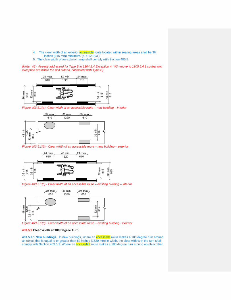
4. The clear width of an exterior accessible route located within seating areas shall be 36 inches (915 mm) minimum. (4-7-12 PC1)
5. The clear width of an exterior ramp shall comply with Section 405.5
(Note: #2 - Already addressed for Type B in 1104.1.4 Exception 4; “#3 –move to 1105.5.4.1 so that unit exception are within the unit criteria, consistent with Type B)
Figure 403.5.1(a)- Clear width of an accessible route – new building – interior
Figure 403.5.1(b) - Clear width of an accessible route – new building – exterior
Figure 403.5.1(c) - Clear width of an accessible route – existing building – interior
Figure 403.5.1(d) - Clear width of an accessible route – existing building - exterior 403.5.2 Clear Width at 180 Degree Turn. 403.5.2.1 New buildings. In new buildings, where an accessible route makes a 180 degree turn around an object that is equal to or greater than 52 inches (1320 mm) in width, the clear widths in the turn shall comply with Section 403.5.1. Where an accessible route makes a 180 degree turn around an object that
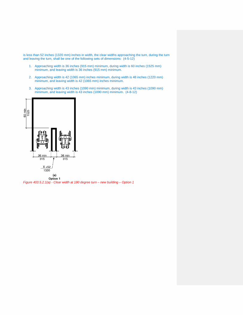
is less than 52 inches (1320 mm) inches in width, the clear widths approaching the turn, during the turn and leaving the turn, shall be one of the following sets of dimensions: (4-5-12)
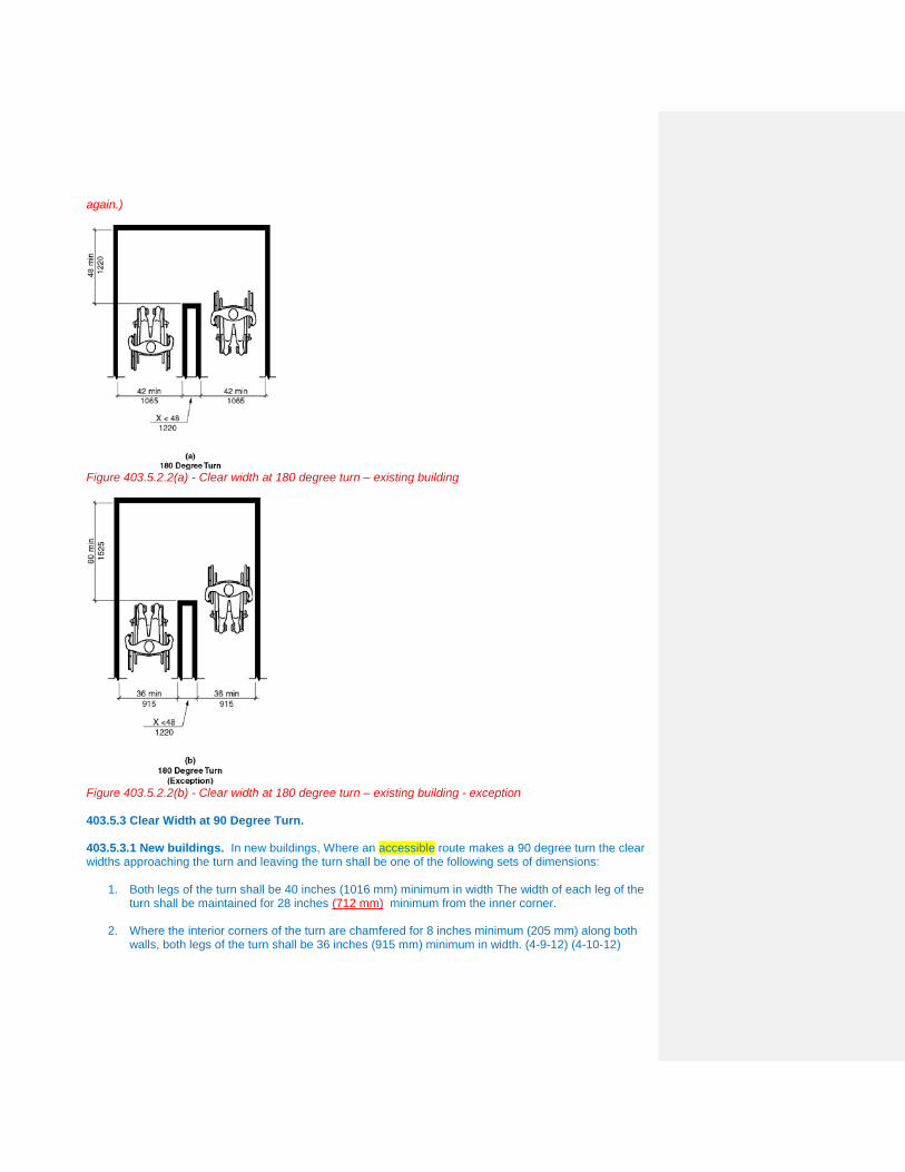
1. Approaching width is 36 inches (915 mm) minimum, during width is 60 inches (1525 mm) minimum, and leaving width is 36 inches (915 mm) minimum.
2. Approaching width is 42 (1065 mm) inches minimum, during width is 48 inches (1220 mm)
minimum, and leaving width is 42 (1065 mm) inches minimum. 3. Approaching width is 43 inches (1090 mm) minimum, during width is 43 inches (1090 mm)
minimum, and leaving width is 43 inches (1090 mm) minimum. (4-8-12)
Figure 403.5.2.1(a) - Clear width at 180 degree turn – new building – Option 1
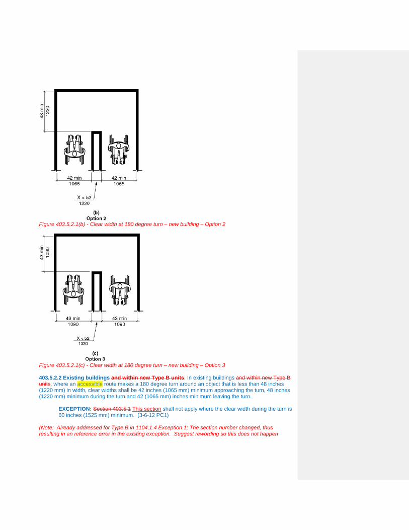
Figure 403.5.2.1(b) - Clear width at 180 degree turn – new building – Option 2
Figure 403.5.2.1(c) - Clear width at 180 degree turn – new building – Option 3 403.5.2.2 Existing buildings and within new Type B units. In existing buildings and within new Type B units, where an accessible route makes a 180 degree turn around an object that is less than 48 inches (1220 mm) in width, clear widths shall be 42 inches (1065 mm) minimum approaching the turn, 48 inches (1220 mm) minimum during the turn and 42 (1065 mm) inches minimum leaving the turn.
EXCEPTION: Section 403.5.1 This section shall not apply where the clear width during the turn is 60 inches (1525 mm) minimum. (3-6-12 PC1)
(Note: Already addressed for Type B in 1104.1.4 Exception 1; The section number changed, thus resulting in an reference error in the existing exception. Suggest rewording so this does not happen
again.)
Figure 403.5.2.2(a) - Clear width at 180 degree turn – existing building
Figure 403.5.2.2(b) - Clear width at 180 degree turn – existing building - exception 403.5.3 Clear Width at 90 Degree Turn. 403.5.3.1 New buildings. In new buildings, Where an accessible route makes a 90 degree turn the clear widths approaching the turn and leaving the turn shall be one of the following sets of dimensions:
1. Both legs of the turn shall be 40 inches (1016 mm) minimum in width The width of each leg of the
turn shall be maintained for 28 inches (712 mm) minimum from the inner corner.
2. Where the interior corners of the turn are chamfered for 8 inches minimum (205 mm) along both walls, both legs of the turn shall be 36 inches (915 mm) minimum in width. (4-9-12) (4-10-12)
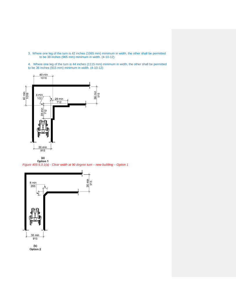
3. Where one leg of the turn is 42 inches (1065 mm) minimum in width, the other shall be permitted to be 38 inches (965 mm) minimum in width. (4-10-12)
4. Where one leg of the turn is 44 inches (1115 mm) minimum in width, the other shall be permitted to be 36 inches (915 mm) minimum in width. (4-10-12)
Figure 403.5.3.1(a) - Clear width at 90 degree turn – new building – Option 1
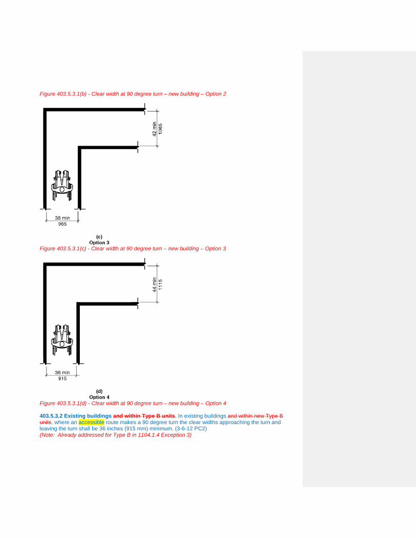
Figure 403.5.3.1(b) - Clear width at 90 degree turn – new building – Option 2
Figure 403.5.3.1(c) - Clear width at 90 degree turn – new building – Option 3
Figure 403.5.3.1(d) - Clear width at 90 degree turn – new building – Option 4 403.5.3.2 Existing buildings and within Type B units. In existing buildings and within new Type B units, where an accessible route makes a 90 degree turn the clear widths approaching the turn and leaving the turn shall be 36 inches (915 mm) minimum. (3-6-12 PC2) (Note: Already addressed for Type B in 1104.1.4 Exception 3)
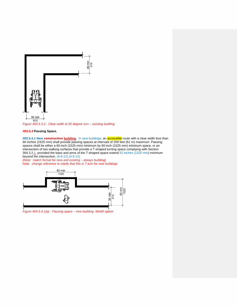
Figure 403.5.3.2 - Clear width at 90 degree turn – existing building 403.5.4 Passing Space. 403.5.4.1 New construction building. In new buildings, an accessible route with a clear width less than 60 inches (1525 mm) shall provide passing spaces at intervals of 200 feet (61 m) maximum. Passing spaces shall be either a 60-inch (1525 mm) minimum by 60-inch (1525 mm) minimum space, or an intersection of two walking surfaces that provide a T-shaped turning space complying with Section 304.3.2.1, provided the base and arms of the T-shaped space extend 52 inches (1320 mm) minimum beyond the intersection. (4-6-12) (4-5-12) (Note: match format for new and existing – always building) Note: change reference to clarify that this is T-turn for new buildings
Figure 403.5.4.1(a) - Passing space – new building- 60x60 option
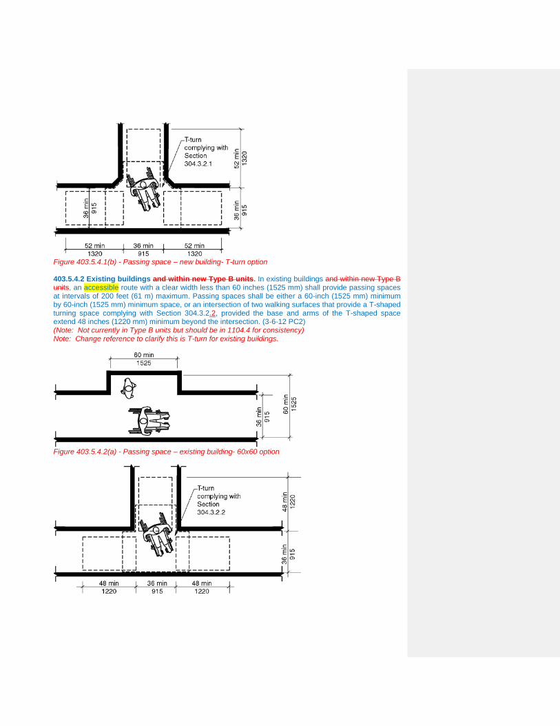
Figure 403.5.4.1(b) - Passing space – new building- T-turn option 403.5.4.2 Existing buildings and within new Type B units. In existing buildings and within new Type B units, an accessible route with a clear width less than 60 inches (1525 mm) shall provide passing spaces at intervals of 200 feet (61 m) maximum. Passing spaces shall be either a 60-inch (1525 mm) minimum by 60-inch (1525 mm) minimum space, or an intersection of two walking surfaces that provide a T-shaped turning space complying with Section 304.3.2.2, provided the base and arms of the T-shaped space extend 48 inches (1220 mm) minimum beyond the intersection. (3-6-12 PC2) (Note: Not currently in Type B units but should be in 1104.4 for consistency) Note: Change reference to clarify this is T-turn for existing buildings.
Figure 403.5.4.2(a) - Passing space – existing building- 60x60 option
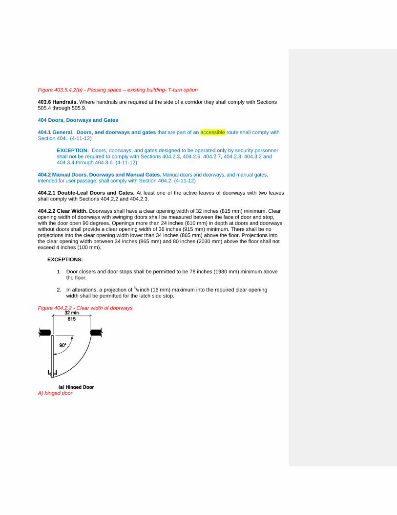
Figure 403.5.4.2(b) - Passing space – existing building- T-turn option 403.6 Handrails. Where handrails are required at the side of a corridor they shall comply with Sections 505.4 through 505.9. 404 Doors, Doorways and Gates 404.1 General. Doors, and doorways and gates that are part of an accessible route shall comply with Section 404. (4-11-12)
EXCEPTION: Doors, doorways, and gates designed to be operated only by security personnel shall not be required to comply with Sections 404.2.3, 404.2.6, 404.2.7, 404.2.8, 404.3.2 and 404.3.4 through 404.3.6. (4-11-12)
404.2 Manual Doors, Doorways and Manual Gates. Manual doors and doorways, and manual gates, intended for user passage, shall comply with Section 404.2. (4-11-12) 404.2.1 Double-Leaf Doors and Gates. At least one of the active leaves of doorways with two leaves shall comply with Sections 404.2.2 and 404.2.3.
404.2.2 Clear Width. Doorways shall have a clear opening width of 32 inches (815 mm) minimum. Clear opening width of doorways with swinging doors shall be measured between the face of door and stop, with the door open 90 degrees. Openings more than 24 inches (610 mm) in depth at doors and doorways without doors shall provide a clear opening width of 36 inches (915 mm) minimum. There shall be no projections into the clear opening width lower than 34 inches (865 mm) above the floor. Projections into the clear opening width between 34 inches (865 mm) and 80 inches (2030 mm) above the floor shall not exceed 4 inches (100 mm).
EXCEPTIONS:
1. Door closers and door stops shall be permitted to be 78 inches (1980 mm) minimum above the floor.
2. In alterations, a projection of 5/8 inch (16 mm) maximum into the required clear opening
width shall be permitted for the latch side stop. Figure 404.2.2 - Clear width of doorways
A) hinged door
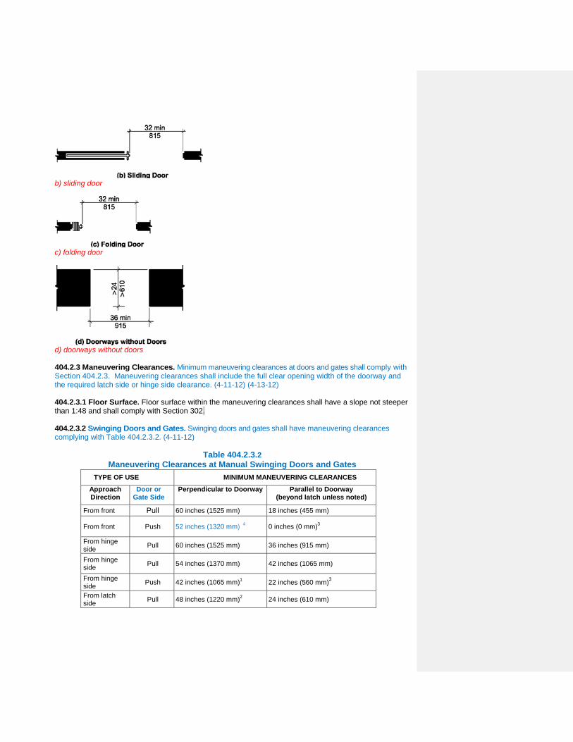
b) sliding door
c) folding door
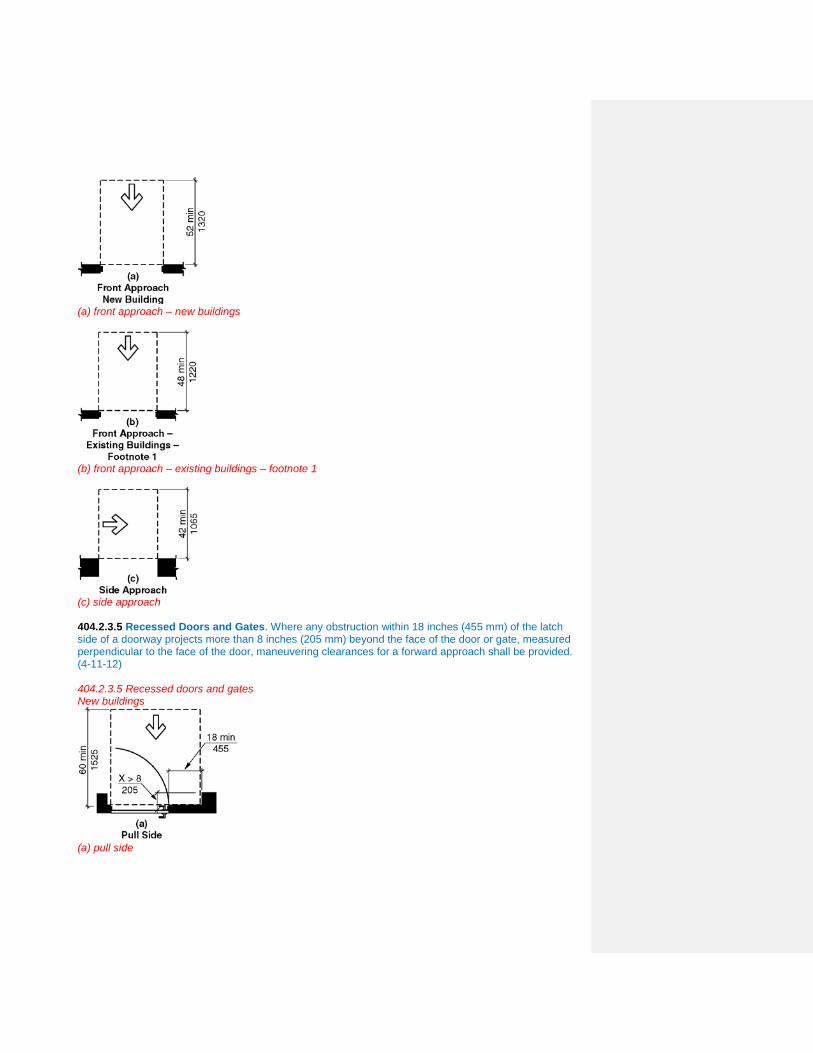
d) doorways without doors 404.2.3 Maneuvering Clearances. Minimum maneuvering clearances at doors and gates shall comply with Section 404.2.3. Maneuvering clearances shall include the full clear opening width of the doorway and the required latch side or hinge side clearance. (4-11-12) (4-13-12)
404.2.3.1 Floor Surface. Floor surface within the maneuvering clearances shall have a slope not steeper than 1:48 and shall comply with Section 302. 404.2.3.2 Swinging Doors and Gates. Swinging doors and gates shall have maneuvering clearances complying with Table 404.2.3.2. (4-11-12)
Table 404.2.3.2
Maneuvering Clearances at Manual Swinging Doors and Gates TYPE OF USE MINIMUM MANEUVERING CLEARANCES
Approach Direction
Door or Gate Side
Perpendicular to Doorway Parallel to Doorway (beyond latch unless noted)
From front Pull 60 inches (1525 mm) 18 inches (455 mm)
From front Push 52 inches (1320 mm) 4 0 inches (0 mm)3
From hinge side Pull 60 inches (1525 mm) 36 inches (915 mm)
From hinge side Pull 54 inches (1370 mm) 42 inches (1065 mm)
From hinge side Push 42 inches (1065 mm)1
22 inches (560 mm)3
From latch side Pull 48 inches (1220 mm)2
24 inches (610 mm)
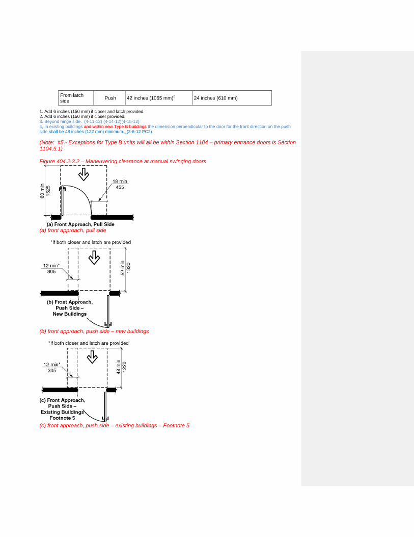
From latch side Push 42 inches (1065 mm)2
24 inches (610 mm)
1. Add 6 inches (150 mm) if closer and latch provided. 2. Add 6 inches (150 mm) if closer provided. 3. Beyond hinge side. (4-11-12) (4-14-12)(4-15-12) 4. In existing buildings and within new Type B buildings the dimension perpendicular to the door for the front direction on the push side shall be 48 inches (122 mm) minimum. (3-6-12 PC2)
(Note: #5 - Exceptions for Type B units will all be within Section 1104 – primary entrance doors is Section 1104.5.1) Figure 404.2.3.2 – Maneuvering clearance at manual swinging doors
(a) front approach, pull side
(b) front approach, push side – new buildings
(c) front approach, push side – existing buildings – Footnote 5
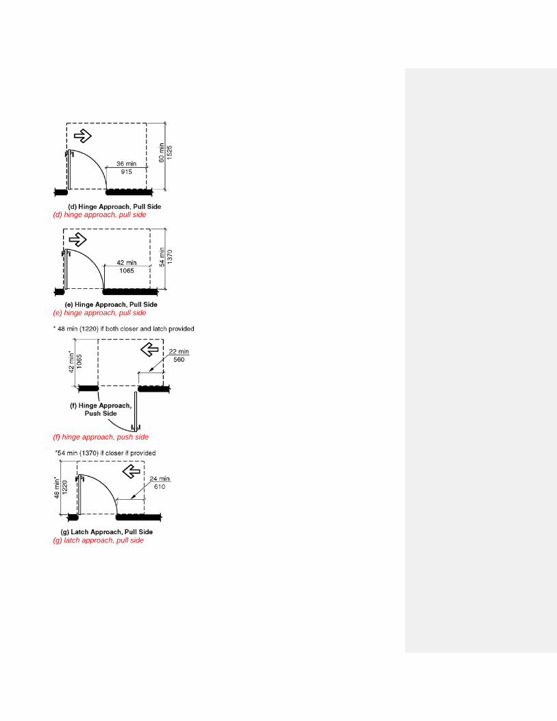
(d) hinge approach, pull side
(e) hinge approach, pull side
(f) hinge approach, push side
(g) latch approach, pull side
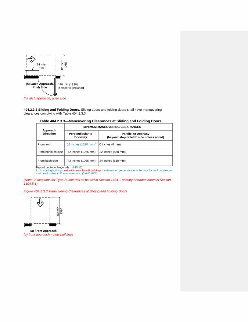
(h) latch approach, push side 404.2.3.3 Sliding and Folding Doors. Sliding doors and folding doors shall have maneuvering clearances complying with Table 404.2.3.3.
Table 404.2.3.3—Maneuvering Clearances at Sliding and Folding Doors
Approach Direction
MINIMUM MANEUVERING CLEARANCES
Perpendicular to Doorway
Parallel to Doorway (beyond stop or latch side unless noted)
From front 52 inches (1320 mm) 2 0 inches (0 mm)
From nonlatch side 42 inches (1065 mm) 22 inches (560 mm)1
From latch side 42 inches (1065 mm) 24 inches (610 mm)
1Beyond pocket or hinge side. (4-15-12) 2. In existing buildings and within new Type B buildings the dimension perpendicular to the door for the front direction shall be 48 inches (122 mm) minimum. (3-6-12 PC2)
(Note: Exceptions for Type B units will all be within Section 1104 – primary entrance doors is Section 1104.5.1) Figure 404.2.3.3 Maneuvering Clearances at Sliding and Folding Doors
(a) front approach – new buildings
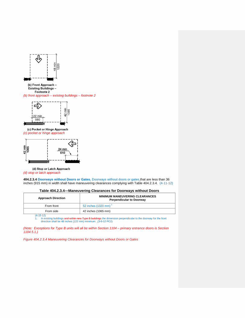
(b) front approach – existing buildings – footnote 2
(c) pocket or hinge approach
(d) stop or latch approach
404.2.3.4 Doorways without Doors or Gates. Doorways without doors or gates that are less than 36 inches (915 mm) in width shall have maneuvering clearances complying with Table 404.2.3.4. (4-11-12)
Table 404.2.3.4—Maneuvering Clearances for Doorways without Doors
Approach Direction MINIMUM MANEUVERING CLEARANCES Perpendicular to Doorway
From front 52 inches (1320 mm) 1
From side 42 inches (1065 mm) (4-15-12) 1. In existing buildings and within new Type B buildings the dimension perpendicular to the doorway for the front
direction shall be 48 inches (122 mm) minimum. (3-6-12 PC2)
(Note: Exceptions for Type B units will all be within Section 1104 – primary entrance doors is Section 1104.5.1.) Figure 404.2.3.4 Maneuvering Clearances for Doorways without Doors or Gates
(a) front approach – new buildings
(b) front approach – existing buildings – footnote 1
(c) side approach 404.2.3.5 Recessed Doors and Gates. Where any obstruction within 18 inches (455 mm) of the latch side of a doorway projects more than 8 inches (205 mm) beyond the face of the door or gate, measured perpendicular to the face of the door, maneuvering clearances for a forward approach shall be provided. (4-11-12) 404.2.3.5 Recessed doors and gates New buildings
(a) pull side
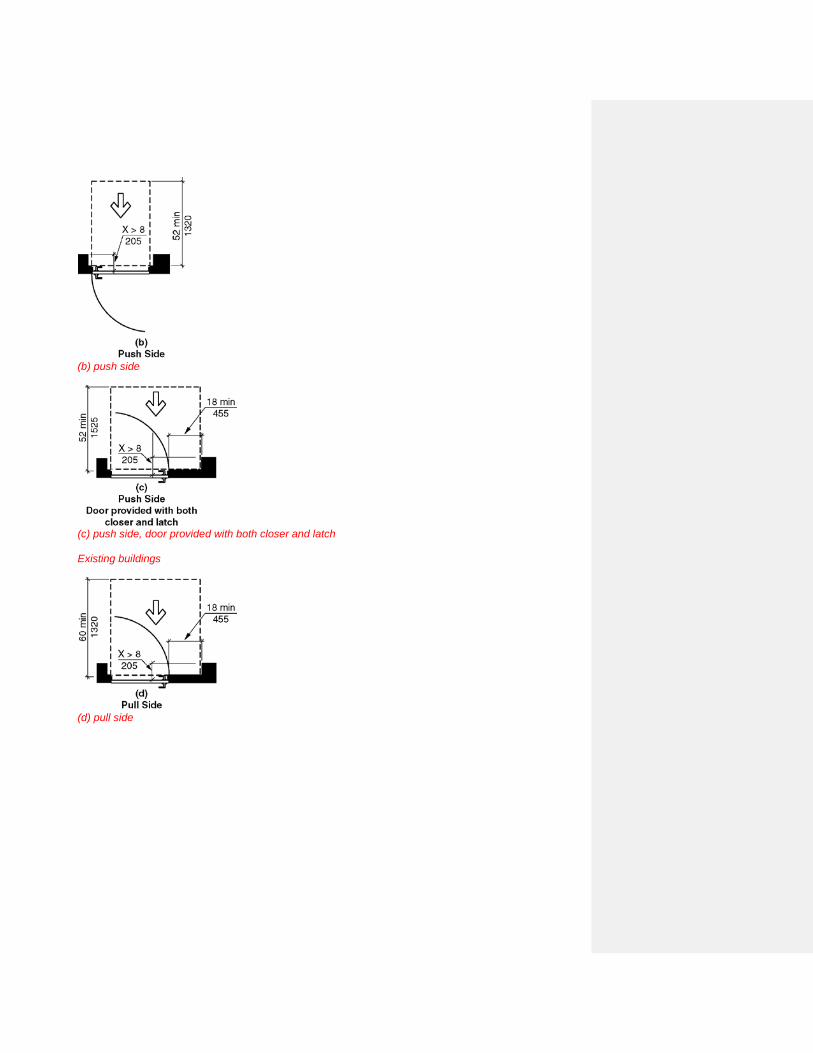
(b) push side
(c) push side, door provided with both closer and latch Existing buildings
(d) pull side
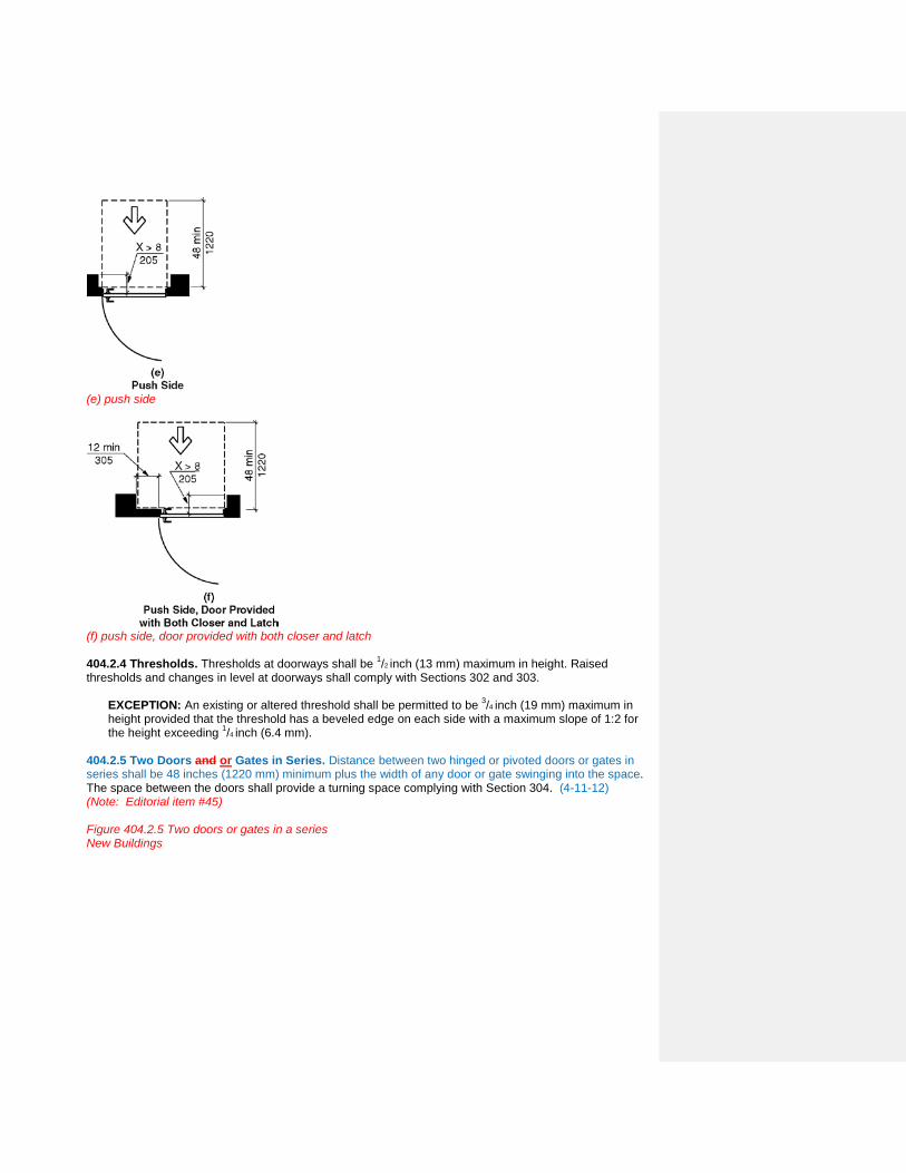
(e) push side
(f) push side, door provided with both closer and latch 404.2.4 Thresholds. Thresholds at doorways shall be 1/2 inch (13 mm) maximum in height. Raised thresholds and changes in level at doorways shall comply with Sections 302 and 303.
EXCEPTION: An existing or altered threshold shall be permitted to be 3/4 inch (19 mm) maximum in height provided that the threshold has a beveled edge on each side with a maximum slope of 1:2 for the height exceeding 1/4 inch (6.4 mm).
404.2.5 Two Doors and or Gates in Series. Distance between two hinged or pivoted doors or gates in series shall be 48 inches (1220 mm) minimum plus the width of any door or gate swinging into the space. The space between the doors shall provide a turning space complying with Section 304. (4-11-12) (Note: Editorial item #45) Figure 404.2.5 Two doors or gates in a series New Buildings
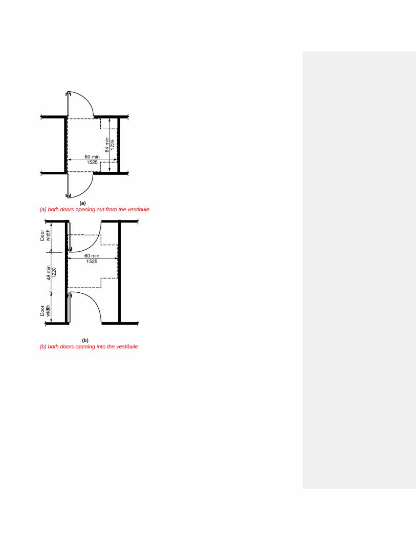
(a) both doors opening out from the vestibule
(b) both doors opening into the vestibule
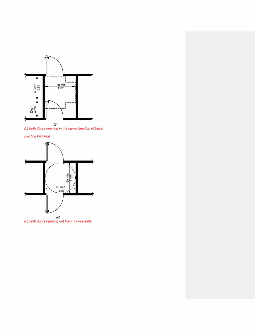
(c) both doors opening in the same direction of travel Existing buildings
(d) both doors opening out from the vestibule
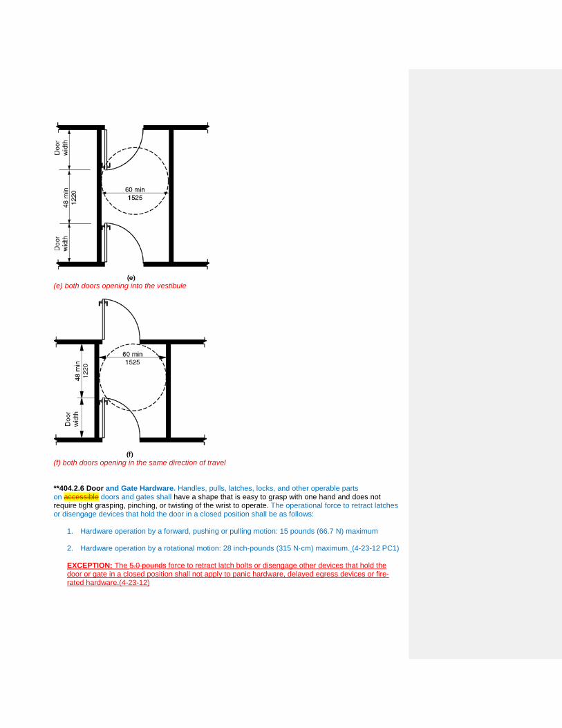
(e) both doors opening into the vestibule
(f) both doors opening in the same direction of travel **404.2.6 Door and Gate Hardware. Handles, pulls, latches, locks, and other operable parts on accessible doors and gates shall have a shape that is easy to grasp with one hand and does not require tight grasping, pinching, or twisting of the wrist to operate. The operational force to retract latches or disengage devices that hold the door in a closed position shall be as follows:
1. Hardware operation by a forward, pushing or pulling motion: 15 pounds (66.7 N) maximum
2. Hardware operation by a rotational motion: 28 inch-pounds (315 N·cm) maximum. (4-23-12 PC1) EXCEPTION: The 5.0 pounds force to retract latch bolts or disengage other devices that hold the door or gate in a closed position shall not apply to panic hardware, delayed egress devices or fire-rated hardware.(4-23-12)
404.2.6.1 Hardware height. Operable parts of such hardware shall be 34 inches (865 mm) minimum and 48 inches (1220 mm) maximum above the floor. Where sliding doors are in the fully open position, operating hardware shall be exposed and usable from both sides. (4-11-12) (Note: Relocated exception form 404.2.8 to 404.2.6. The committee agreed that panic hardware and fire hardware should not have to meet the force limits for safety reasons associated with door performance during fires and crowd action during an emergency. The committee then approve a new specific force for door hardware. The exception is applicable to the door hardware, not the door opening force, so this exception should be relocated to the appropriate section. The hardware height is in a separate section because text after an exception is difficult to keep in the correct application.. 404.2.7 Closing Speed. Door and gate closing speed shall comply with 404.2.8 404.2.7.(4-11-12) 404.2.7.1 Door Closers and Gate Closers. Door closers and gate closers shall be adjusted so that from an open position of 90 degrees, the time required to move the door to an open position of 12 degrees shall be 5 seconds minimum. (4-11-12) 404.2.7.2 Spring Hinges. Door and gate spring hinges shall be adjusted so that from an open position of 70 degrees, the door or gate shall move to the closed position in 1.5 seconds minimum. (4-11-12) **404.2.8 Door and Gate-Opening Force. Fire doors and doors required to be equipped with panic hardware, break away features or other factors requiring higher opening force for safety reasons shall have the minimum opening force allowable in scoping provisions adopted by the appropriate administrative authority. For other doors, the force for pushing or pulling open doors or gates shall be as follows: (4-23-12) (4-11-12)(4-23-12 PC1)
1. Interior hinged doors and gates: 5.0 pounds (22.2 N) maximum. (4-11-12) 2. Sliding or folding doors: 5.0 pounds (22.2 N) maximum.
Opening forces for exterior sliding doors shall be determined in accordance with AAMA 513 listed in Section 106.2.13. (4-23-12 PC2)
EXCEPTION: The 5.0 pounds force to retract latch bolts or disengage other devices that hold the door or gate in a closed position shall not apply to panic hardware, delayed egress devices or fire-rated hardware.(4-23-12) (Note: See notes on Section 404.2.6 for relocation of exception) (Question: 4-23-12 PC2.1, Agenda #9 got rid of item #3 for exterior door force requirements, so there is nothing for this to apply to. Delete)
404.2.9 Door and Gate Surface. Door and gate surfaces within 10 inches (255 mm) of the floor, measured vertically, shall be a smooth surface on the push side extending the full width of the door or gate. Door and gate hardware, or any other obstruction or protrusion shall not be mounted in nor extend into the area within 10 inches (255 mm) of the floor. Parts creating horizontal or vertical joints in the smooth surface shall be within 1/16 inch (1.6 mm) of the same plane as the other. Cavities created by added kick plates shall be capped. (4-27-12) (4-11-12)
EXCEPTIONS:
1. Sliding doors shall not be required to comply with Section 404.2.9 this section.
2. Tempered glass doors without stiles and having a bottom rail or shoe with the top leading edge tapered at no less than 60 degrees from the horizontal shall not be required to comply with the 10-inch (255 mm) bottom rail height requirement.
3. Doors and gates that do not extend to within 10 inches (255 mm) of the floor shall not be required to
comply with Section 404.2.9 this section. (4-11-12)
4. The installation of kick plates on existing doors and gates without a smooth surface within 10 inches (255 mm) of the floor shall be permitted. The kick plates shall extend to 10 inches (255 mm) above the floor and no more than 1 inch (26 mm) from the sides and bottom of the door. Cavities created by such kickplates shall be capped. (4-29-12)
(Note: consistency in exception language – see 404.3.4 exception 1 and 2)
404.2.10 Vision Lites. Doors, gates and sidelites adjacent to doors or gates containing one or more glazing panels that permit viewing through the panels shall have the bottom of at least one panel on either the door or an adjacent sidelite 43 inches (1090 mm) maximum above the floor. (4-11-12)
EXCEPTION: Vision lites with the lowest part more than 66 inches (1675 mm) above the floor shall not be required to comply with Section 404.2.10 this section.
(Note: consistency in exception language – see 404.3.4 exception 1 and 2) 404.3 Automatic Doors and Power-Assisted Doors and Gates. Automatic doors and automatic gates shall comply with Section 404.3. Full powered automatic doors and gates shall comply with ANSI/BHMA A156.10 listed in Section 106.2.8. Power–assist doors and gates and low–energy automatic doors and gates shall comply with ANSI/BHMA A156.19 listed in Section 106.2.7 (4-11-12) (4-30-12) (4-31-12 PC1) 404.3.1 Public Entrances. Where an automatic door is provided at a building or facility public entrance, it shall be a full powered automatic door or a low-energy automatic door. (4-33-12 PC1.1) (Note: consistent use of the term through Section 404.3) 404.3.2 Vestibules. Where the an entrance includes a vestibule at least one exterior door and one interior door in the vestibule shall have the same type of automatic door opener. (4-33-12 PC1.1) 404.3.3 Clear Width. Doorways shall have a clear opening width of 32 inches (815 mm) in power-on and power-off mode. The minimum clear opening width for automatic door systems shall be based on the clear opening width provided with all leafs in the open position. 404.3.4 Maneuvering Clearances. Maneuvering clearances at power–assisted doors and gates shall comply with Section 404.2.3. Maneuvering clearances complying with Section 404.2.3 shall be provided on the egress side of low-energy automatic doors and gates and full power automatic doors and gates that serve as part of the accessible means of egress. (4-30-12 PC1)(4-11-12)(4-31-12 PC1)
EXCEPTIONS:
1. Low-energy automatic doors and gates and full power automatic doors and gates that have standby power or battery back-up shall not be required to comply with this section.
2. Low-energy automatic doors and gates and full power automatic doors and gates that remain open in the power-off condition shall not be required to comply with this section.
3. Full power automatic sliding doors and gates that include a break-away feature shall not be required to comply with this section.(4-31-12 PC1)
404.3.5 Thresholds. Thresholds and changes in level at doorways shall comply with Section 404.2.4. 404.3.6 Two Doors or Gates in Series. Doors or gates in series shall comply with Section 404.2.5. (4-11-12)
EXCEPTION: Where both doors or gates in a series are power assist doors, low energy automatic doors or full power automatic doors, the two doors and gates in a series shall not be required to provide a turning space between the doors. (4-34-12 PC1.1)(4-34-12/1.1-PC1.1 Agenda item #13.1)
Comment [KP1]: Alan shows as struck out. Do not agree. This is a large technical difference from IBC.
Comment [KR2]: Accessible can not be eliminated here because of link to egress provisions in IBC.
404.3.7 Controls. Manually operated controls shall comply with Section 309. The clear floor space adjacent to the control shall be located beyond the arc of door swings. (4-34-12) (4-30-12)(4-31-12) 404.3.8 Door and Gate Hardware. Handles, pulls, latches, locks, and other operable parts shall comply with Section 404.2.6. (4-34-12) 404.3.9 Break Out Opening. Where full power automatic sliding doors and gates are equipped with a break out feature, the clear break out opening shall be 32 inches (815 mm) minimum when operated in emergency mode. (4-31-12) 405 Ramps 405.1 General. Ramps along accessible routes shall comply with Section 405.
EXCEPTION: In assembly areas, aisle ramps adjacent to seating and not serving elements required to be on an accessible route shall not be required to comply with Section 405.
405.2 Slope. Ramp runs shall have a running slope greater than 1:20 and not steeper than 1:12.
EXCEPTION: In existing buildings or facilities, ramps shall be permitted to have slopes steeper than 1:12 complying with Table 405.2 where such slopes are necessary due to space limitations.
Table 405.2—Allowable Ramp Dimensions for Construction in
Existing Sites, Buildings, and Facilities Slope1
Maximum Rise
Steeper than 1:10 but not steeper than 1:8 3 inches (75 mm)
Steeper than 1:12 but not steeper than 1:10 6 inches (150 mm) 1A slope steeper than 1:8 shall not be permitted.
405.3 Cross Slope. Cross slope of ramp runs shall not be steeper than 1:48. 405.4 Floor Surfaces. Floor surfaces of ramp runs shall comply with Section 302. 405.5 Clear Width. The clear width of a ramp run shall be 36 inches (915 mm) minimum. Handrails and handrail supports that are provided on the ramp run shall not project into the required clear width of the ramp run.
EXCEPTION: Within employee work areas, the required clear width of ramps that are a part of common use circulation paths shall be permitted to be decreased by work area equipment provided that the decrease is essential to the function of the work being performed. (4-38-12)
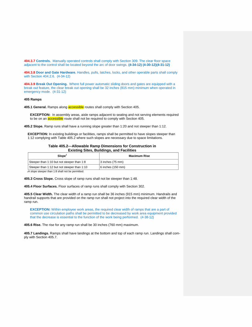
405.6 Rise. The rise for any ramp run shall be 30 inches (760 mm) maximum. 405.7 Landings. Ramps shall have landings at the bottom and top of each ramp run. Landings shall com-ply with Section 405.7.
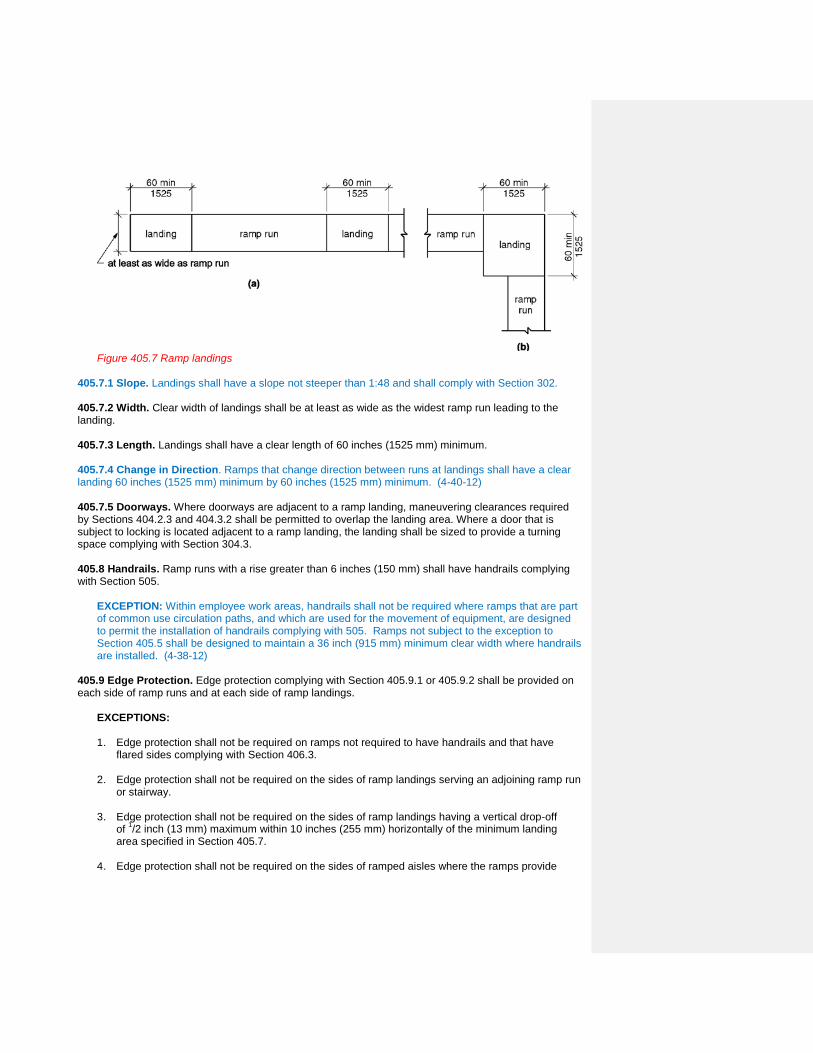
Figure 405.7 Ramp landings
405.7.1 Slope. Landings shall have a slope not steeper than 1:48 and shall comply with Section 302.
405.7.2 Width. Clear width of landings shall be at least as wide as the widest ramp run leading to the landing.
405.7.3 Length. Landings shall have a clear length of 60 inches (1525 mm) minimum.
405.7.4 Change in Direction. Ramps that change direction between runs at landings shall have a clear landing 60 inches (1525 mm) minimum by 60 inches (1525 mm) minimum. (4-40-12)
405.7.5 Doorways. Where doorways are adjacent to a ramp landing, maneuvering clearances required by Sections 404.2.3 and 404.3.2 shall be permitted to overlap the landing area. Where a door that is subject to locking is located adjacent to a ramp landing, the landing shall be sized to provide a turning space complying with Section 304.3. 405.8 Handrails. Ramp runs with a rise greater than 6 inches (150 mm) shall have handrails complying with Section 505.
EXCEPTION: Within employee work areas, handrails shall not be required where ramps that are part of common use circulation paths, and which are used for the movement of equipment, are designed to permit the installation of handrails complying with 505. Ramps not subject to the exception to Section 405.5 shall be designed to maintain a 36 inch (915 mm) minimum clear width where handrails are installed. (4-38-12)
405.9 Edge Protection. Edge protection complying with Section 405.9.1 or 405.9.2 shall be provided on each side of ramp runs and at each side of ramp landings.
EXCEPTIONS: 1. Edge protection shall not be required on ramps not required to have handrails and that have
flared sides complying with Section 406.3.
2. Edge protection shall not be required on the sides of ramp landings serving an adjoining ramp run or stairway.
3. Edge protection shall not be required on the sides of ramp landings having a vertical drop-off of 1/2 inch (13 mm) maximum within 10 inches (255 mm) horizontally of the minimum landing area specified in Section 405.7.
4. Edge protection shall not be required on the sides of ramped aisles where the ramps provide
access to the adjacent seats and aisle access ways.
Figure 405.9 Edge protection – limited drop off – Exception 3
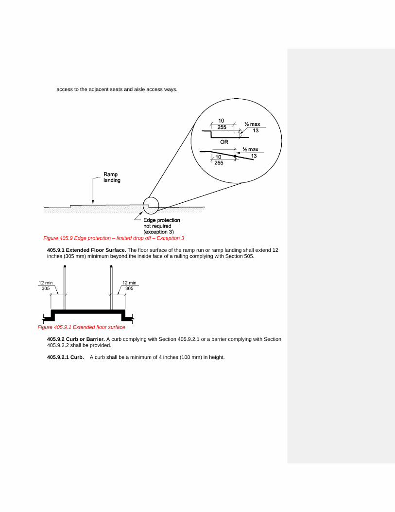
405.9.1 Extended Floor Surface. The floor surface of the ramp run or ramp landing shall extend 12 inches (305 mm) minimum beyond the inside face of a railing complying with Section 505.
Figure 405.9.1 Extended floor surface
405.9.2 Curb or Barrier. A curb complying with Section 405.9.2.1 or a barrier complying with Section 405.9.2.2 shall be provided. 405.9.2.1 Curb. A curb shall be a minimum of 4 inches (100 mm) in height.
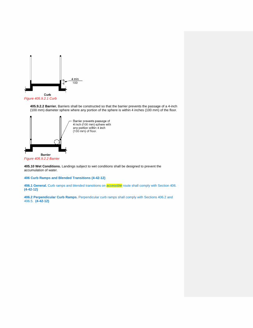
Figure 405.9.2.1 Curb
405.9.2.2 Barrier. Barriers shall be constructed so that the barrier prevents the passage of a 4-inch (100 mm) diameter sphere where any portion of the sphere is within 4 inches (100 mm) of the floor.
Figure 405.9.2.2 Barrier
405.10 Wet Conditions. Landings subject to wet conditions shall be designed to prevent the accumulation of water. 406 Curb Ramps and Blended Transitions (4-42-12) 406.1 General. Curb ramps and blended transitions on accessible route shall comply with Section 406. (4-42-12) 406.2 Perpendicular Curb Ramps. Perpendicular curb ramps shall comply with Sections 406.2 and 406.5. (4-42-12)
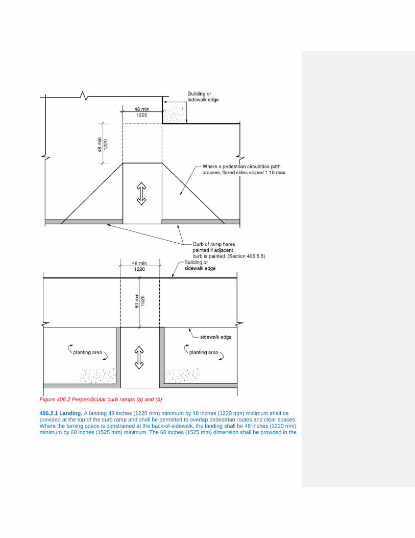
Figure 406.2 Perpendicular curb ramps (a) and (b) 406.2.1 Landing. A landing 48 inches (1220 mm) minimum by 48 inches (1220 mm) minimum shall be provided at the top of the curb ramp and shall be permitted to overlap pedestrian routes and clear spaces. Where the turning space is constrained at the back-of-sidewalk, the landing shall be 48 inches (1220 mm) minimum by 60 inches (1525 mm) minimum. The 60 inches (1525 mm) dimension shall be provided in the
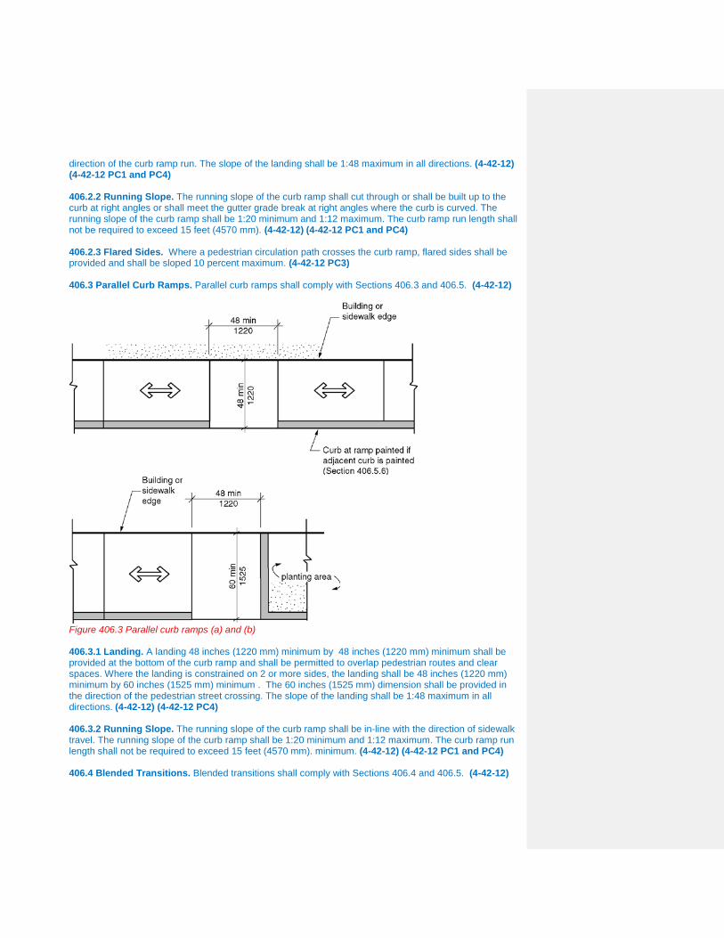
direction of the curb ramp run. The slope of the landing shall be 1:48 maximum in all directions. (4-42-12) (4-42-12 PC1 and PC4) 406.2.2 Running Slope. The running slope of the curb ramp shall cut through or shall be built up to the curb at right angles or shall meet the gutter grade break at right angles where the curb is curved. The running slope of the curb ramp shall be 1:20 minimum and 1:12 maximum. The curb ramp run length shall not be required to exceed 15 feet (4570 mm). (4-42-12) (4-42-12 PC1 and PC4) 406.2.3 Flared Sides. Where a pedestrian circulation path crosses the curb ramp, flared sides shall be provided and shall be sloped 10 percent maximum. (4-42-12 PC3) 406.3 Parallel Curb Ramps. Parallel curb ramps shall comply with Sections 406.3 and 406.5. (4-42-12)
Figure 406.3 Parallel curb ramps (a) and (b) 406.3.1 Landing. A landing 48 inches (1220 mm) minimum by 48 inches (1220 mm) minimum shall be provided at the bottom of the curb ramp and shall be permitted to overlap pedestrian routes and clear spaces. Where the landing is constrained on 2 or more sides, the landing shall be 48 inches (1220 mm) minimum by 60 inches (1525 mm) minimum . The 60 inches (1525 mm) dimension shall be provided in the direction of the pedestrian street crossing. The slope of the landing shall be 1:48 maximum in all directions. (4-42-12) (4-42-12 PC4) 406.3.2 Running Slope. The running slope of the curb ramp shall be in-line with the direction of sidewalk travel. The running slope of the curb ramp shall be 1:20 minimum and 1:12 maximum. The curb ramp run length shall not be required to exceed 15 feet (4570 mm). minimum. (4-42-12) (4-42-12 PC1 and PC4) 406.4 Blended Transitions. Blended transitions shall comply with Sections 406.4 and 406.5. (4-42-12)
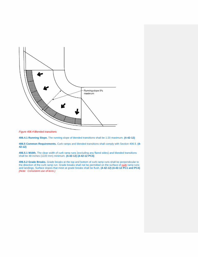
Figure 406.4 Blended transitions 406.4.1 Running Slope. The running slope of blended transitions shall be 1:20 maximum. (4-42-12) 406.5 Common Requirements. Curb ramps and blended transitions shall comply with Section 406.5. (4-42-12) 406.5.1 Width. The clear width of curb ramp runs (excluding any flared sides) and blended transitions shall be 48 inches (1220 mm) minimum. (4-42-12) (4-42-12 PC4) 406.5.2 Grade Breaks. Grade breaks at the top and bottom of curb ramp runs shall be perpendicular to the direction of the curb ramp run. Grade breaks shall not be permitted on the surface of curb ramp runs and landings. Surface slopes that meet at grade breaks shall be flush. (4-42-12) (4-42-12 PC1 and PC4) (Note: Consistent use of term.)
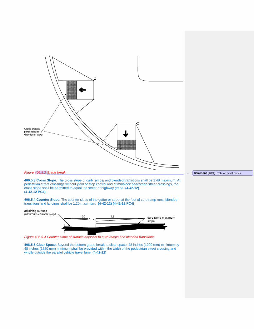
Figure 406.5.2 Grade break 406.5.3 Cross Slope. The cross slope of curb ramps, and blended transitions shall be 1:48 maximum. At pedestrian street crossings without yield or stop control and at midblock pedestrian street crossings, the cross slope shall be permitted to equal the street or highway grade. (4-42-12) (4-42-12 PC4) 406.5.4 Counter Slope. The counter slope of the gutter or street at the foot of curb ramp runs, blended transitions and landings shall be 1:20 maximum. (4-42-12) (4-42-12 PC4)
Figure 406.5.4 Counter slope of surface adjacent to curb ramps and blended transitions 406.5.5 Clear Space. Beyond the bottom grade break, a clear space 48 inches (1220 mm) minimum by 48 inches (1220 mm) minimum shall be provided within the width of the pedestrian street crossing and wholly outside the parallel vehicle travel lane. (4-42-12)
Comment [KP3]: Take off small circles
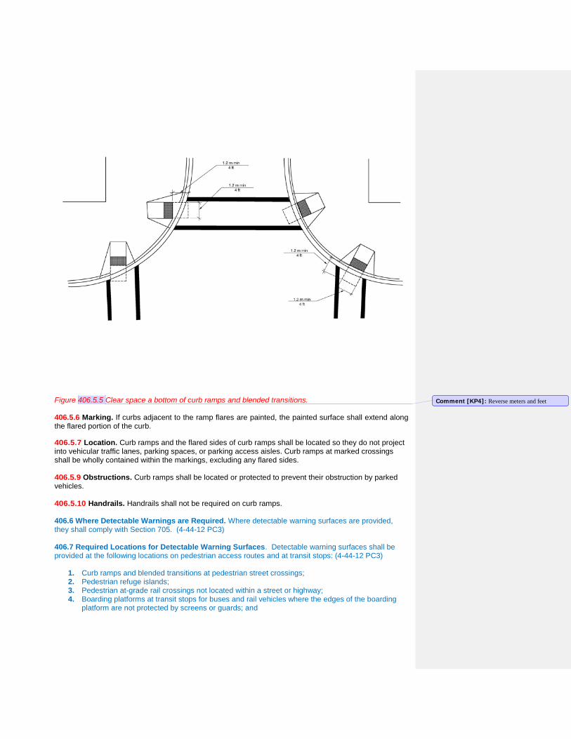
Figure 406.5.5 Clear space a bottom of curb ramps and blended transitions. 406.5.6 Marking. If curbs adjacent to the ramp flares are painted, the painted surface shall extend along the flared portion of the curb.
406.5.7 Location. Curb ramps and the flared sides of curb ramps shall be located so they do not project into vehicular traffic lanes, parking spaces, or parking access aisles. Curb ramps at marked crossings shall be wholly contained within the markings, excluding any flared sides. 406.5.9 Obstructions. Curb ramps shall be located or protected to prevent their obstruction by parked vehicles. 406.5.10 Handrails. Handrails shall not be required on curb ramps. 406.6 Where Detectable Warnings are Required. Where detectable warning surfaces are provided, they shall comply with Section 705. (4-44-12 PC3)
406.7 Required Locations for Detectable Warning Surfaces. Detectable warning surfaces shall be provided at the following locations on pedestrian access routes and at transit stops: (4-44-12 PC3)
1. Curb ramps and blended transitions at pedestrian street crossings; 2. Pedestrian refuge islands; 3. Pedestrian at-grade rail crossings not located within a street or highway; 4. Boarding platforms at transit stops for buses and rail vehicles where the edges of the boarding
platform are not protected by screens or guards; and
Comment [KP4]: Reverse meters and feet
5. Boarding and alighting areas at sidewalk or street level transit stops for rail vehicles where the side of the boarding and alighting areas facing the rail vehicles is not protected by screens or guards.
Exception: Detectable warning surfaces are shall not be required at pedestrian refuge islands that are cut-through at street level and are less than 6 feet (1830 mm) in length in the direction of pedestrian travel. (4-44-12)
(Note: Editorial #59 – good code language)
407 Elevators 407.1 General. Elevators shall comply with Section 407 and ASME A17.1/CSA B44 listed in Section 106.2.9. Elevators shall be passenger elevators as classified by ASME A17.1/CSA B44. Elevator operation shall be automatic. 407.2 Elevator Landing Requirements. Elevator landings shall comply with Section 407.2.
407.2.1 Call Controls. Where elevator call buttons or keypads are provided, they shall comply with Sections 407.2.1 and 309.4. Call buttons shall be raised or flush. Objects beneath hall call buttons shall protrude 1 inch (25 mm) maximum.
EXCEPTIONS: 1. Existing elevators shall be permitted to have recessed call buttons. 2. The restriction on objects beneath call buttons shall not apply to existing call buttons.
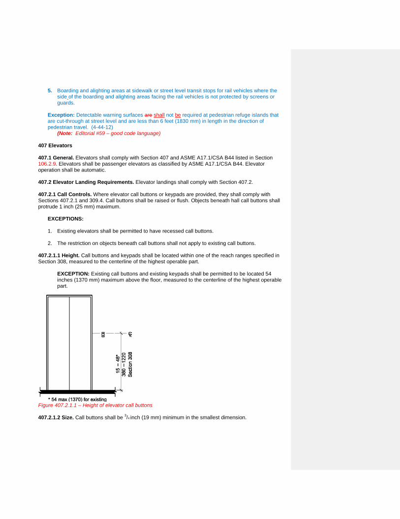
407.2.1.1 Height. Call buttons and keypads shall be located within one of the reach ranges specified in Section 308, measured to the centerline of the highest operable part.
EXCEPTION: Existing call buttons and existing keypads shall be permitted to be located 54 inches (1370 mm) maximum above the floor, measured to the centerline of the highest operable part.
Figure 407.2.1.1 – Height of elevator call buttons
407.2.1.2 Size. Call buttons shall be 3/4 inch (19 mm) minimum in the smallest dimension.
EXCEPTION: Existing elevator call buttons shall not be required to comply with Section 407.2.1.2.
407.2.1.3 Clear Floor Space. A clear floor space complying with Section 305 shall be provided at call controls.
407.2.1.4 Location. The call button that designates the up direction shall be located above the call button that designates the down direction.
EXCEPTION: Destination-oriented elevators shall not be required to comply with Section 407.2.1.4.
407.2.1.5 Signals. Call buttons shall have visible signals to indicate when each call is registered and when each call is answered. Call buttons shall provide an audible signal or mechanical motion of the button to indicate when each call is registered.
EXCEPTIONS: 1. Destination-oriented elevators shall not be required to comply with Section 407.2.1.5, provided
a visible signal and audible tones and verbal announcements complying with Section 407.2.1.7 are provided.
2. Existing elevators shall not be required to comply with Section 407.2.1.5.
407.2.1.6 Keypads. Where keypads are provided, keypads shall be in a standard telephone keypad arrangement and shall comply with Section 407.4.7.2.
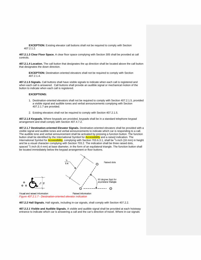
407.2.1.7 Destination-oriented Elevator Signals. Destination-oriented elevators shall be provided with a visible signal and audible tones and verbal announcements to indicate which car is responding to a call. The audible tone and verbal announcement shall be activated by pressing a function button. The function button shall be identified by the International Symbol for Accessibility and a raised indication. The International Symbol for Accessibility, complying with Section 703.6.3.1, shall be 5/8 inch (16 mm) in height and be a visual character complying with Section 703.2. The indication shall be three raised dots, spaced 1/4 inch (6.4 mm) at base diameter, in the form of an equilateral triangle. The function button shall be located immediately below the keypad arrangement or floor buttons.
Figure 407.2.1.7 - Destination-oriented elevator indication 407.2.2 Hall Signals. Hall signals, including in-car signals, shall comply with Section 407.2.2.
407.2.2.1 Visible and Audible Signals. A visible and audible signal shall be provided at each hoistway entrance to indicate which car is answering a call and the car’s direction of travel. Where in-car signals
are provided they shall be visible from the floor area adjacent to the hall call buttons. EXCEPTIONS: 1. Destination-oriented elevators shall not be required to comply with Section 407.2.2.1,
provided a visible signal and audible tones and verbal announcements complying with Section 407.2.1.7 are provided.
2. In existing elevators, a signal indicating the direction of car travel shall not be required.
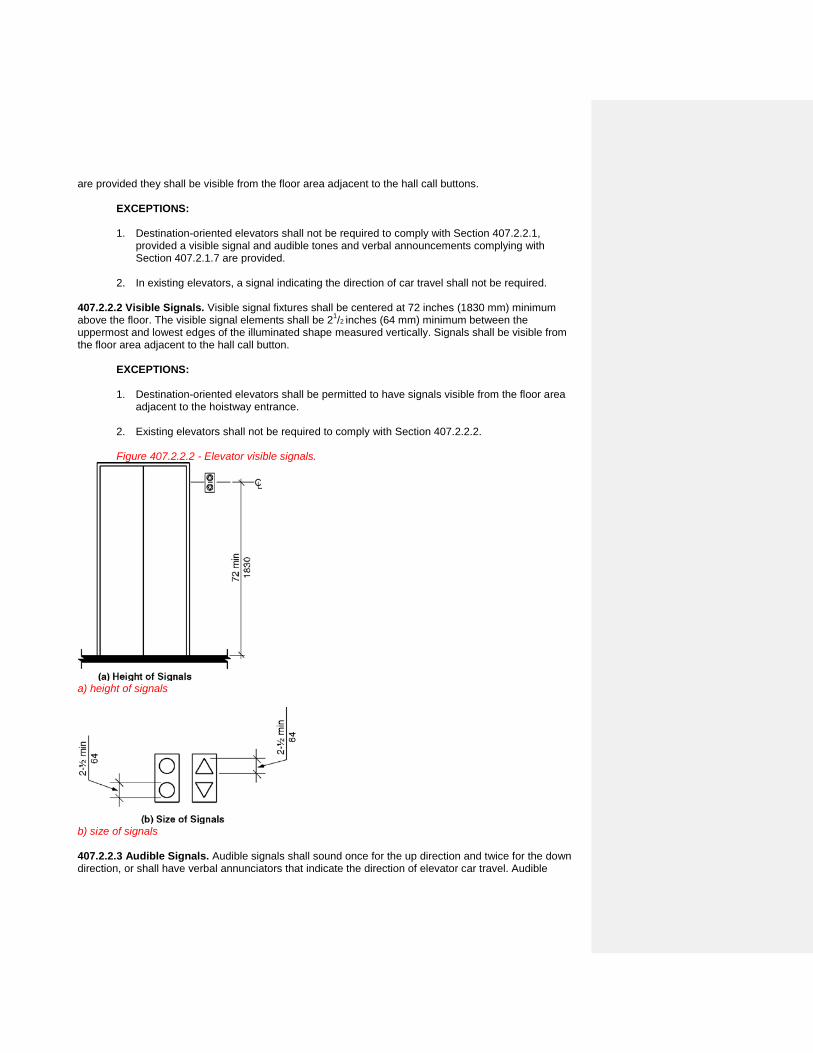
407.2.2.2 Visible Signals. Visible signal fixtures shall be centered at 72 inches (1830 mm) minimum above the floor. The visible signal elements shall be 21/2 inches (64 mm) minimum between the uppermost and lowest edges of the illuminated shape measured vertically. Signals shall be visible from the floor area adjacent to the hall call button.
EXCEPTIONS: 1. Destination-oriented elevators shall be permitted to have signals visible from the floor area
adjacent to the hoistway entrance.
2. Existing elevators shall not be required to comply with Section 407.2.2.2. Figure 407.2.2.2 - Elevator visible signals.
a) height of signals
b) size of signals 407.2.2.3 Audible Signals. Audible signals shall sound once for the up direction and twice for the down direction, or shall have verbal annunciators that indicate the direction of elevator car travel. Audible
signals shall have a frequency of 1500 Hz maximum. Verbal annunciators shall have a frequency of 300 Hz minimum and 3,000 Hz maximum. The audible signal or verbal annunciator shall be 10 dBA minimum above ambient, but shall not exceed 80 dBA, measured at the hall call button.
EXCEPTIONS: 1. Destination-oriented elevators shall not be required to comply with Section 407.2.2.3,
provided the audible tone and verbal announcement is the same as those given at the call button or call button keypad.
2. The requirement for the frequency and range of audible signals shall not apply in existing elevators.
407.2.2.4 Differentiation. Each destination-oriented elevator in a bank of elevators shall have audible and visible means for differentiation.
407.2.3 Hoistway Signs. Signs at elevator hoistways shall comply with Section 407.2.3.
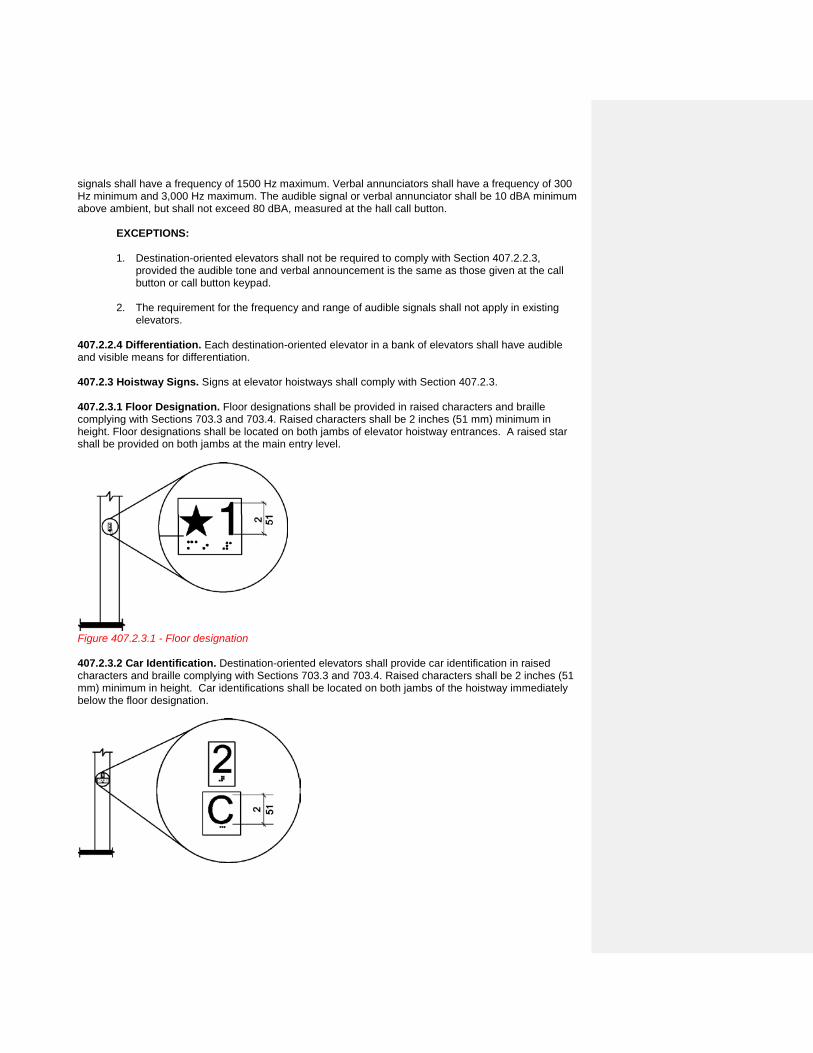
407.2.3.1 Floor Designation. Floor designations shall be provided in raised characters and braille complying with Sections 703.3 and 703.4. Raised characters shall be 2 inches (51 mm) minimum in height. Floor designations shall be located on both jambs of elevator hoistway entrances. A raised star shall be provided on both jambs at the main entry level.
Figure 407.2.3.1 - Floor designation
407.2.3.2 Car Identification. Destination-oriented elevators shall provide car identification in raised characters and braille complying with Sections 703.3 and 703.4. Raised characters shall be 2 inches (51 mm) minimum in height. Car identifications shall be located on both jambs of the hoistway immediately below the floor designation.
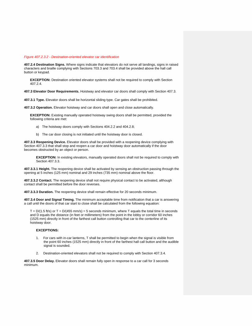
Figure 407.2.3.2 - Destination-oriented elevator car identification
407.2.4 Destination Signs. Where signs indicate that elevators do not serve all landings, signs in raised characters and braille complying with Sections 703.3 and 703.4 shall be provided above the hall call button or keypad.
EXCEPTION: Destination oriented elevator systems shall not be required to comply with Section 407.2.4.
407.3 Elevator Door Requirements. Hoistway and elevator car doors shall comply with Section 407.3.
407.3.1 Type. Elevator doors shall be horizontal sliding type. Car gates shall be prohibited. 407.3.2 Operation. Elevator hoistway and car doors shall open and close automatically.
EXCEPTION: Existing manually operated hoistway swing doors shall be permitted, provided the following criteria are met:
a) The hoistway doors comply with Sections 404.2.2 and 404.2.8; b) The car door closing is not initiated until the hoistway door is closed.
407.3.3 Reopening Device. Elevator doors shall be provided with a reopening device complying with Section 407.3.3 that shall stop and reopen a car door and hoistway door automatically if the door becomes obstructed by an object or person.
EXCEPTION: In existing elevators, manually operated doors shall not be required to comply with Section 407.3.3.
407.3.3.1 Height. The reopening device shall be activated by sensing an obstruction passing through the opening at 5 inches (125 mm) nominal and 29 inches (735 mm) nominal above the floor.
407.3.3.2 Contact. The reopening device shall not require physical contact to be activated, although contact shall be permitted before the door reverses.
407.3.3.3 Duration. The reopening device shall remain effective for 20 seconds minimum. 407.3.4 Door and Signal Timing. The minimum acceptable time from notification that a car is answering a call until the doors of that car start to close shall be calculated from the following equation:
T = D/(1.5 ft/s) or T = D/(455 mm/s) = 5 seconds minimum, where T equals the total time in seconds and D equals the distance (in feet or millimeters) from the point in the lobby or corridor 60 inches (1525 mm) directly in front of the farthest call button controlling that car to the centerline of its hoistway door.
EXCEPTIONS: 1. For cars with in-car lanterns, T shall be permitted to begin when the signal is visible from
the point 60 inches (1525 mm) directly in front of the farthest hall call button and the audible signal is sounded.
2. Destination-oriented elevators shall not be required to comply with Section 407.3.4.
407.3.5 Door Delay. Elevator doors shall remain fully open in response to a car call for 3 seconds minimum.
407.3.6 Width. Elevator door clear opening width shall comply with Table 407.4.1. EXCEPTION: In existing elevators, a power-operated car door complying with Section 404.2.2 shall be permitted.
407.4 Elevator Car Requirements. Elevator cars shall comply with Section 407.4.
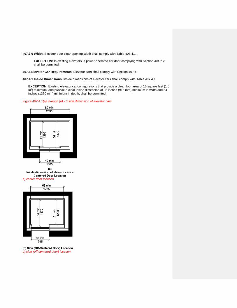
407.4.1 Inside Dimensions. Inside dimensions of elevator cars shall comply with Table 407.4.1.
EXCEPTION: Existing elevator car configurations that provide a clear floor area of 16 square feet (1.5 m2) minimum, and provide a clear inside dimension of 36 inches (915 mm) minimum in width and 54 inches (1370 mm) minimum in depth, shall be permitted.
Figure 407.4.1(a) through (e) - Inside dimension of elevator cars
a) center door location
b) side (off-centered door) location
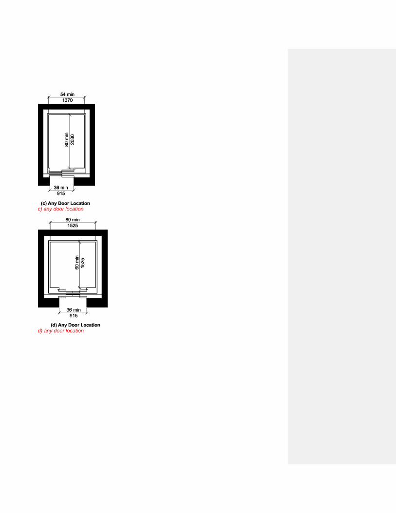
c) any door location
d) any door location
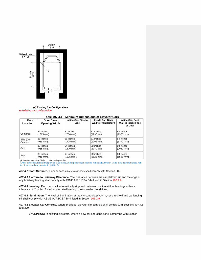
e) existing car configuration
Table 407.4.1—Minimum Dimensions of Elevator Cars
Door Location
Door Clear Opening Width
Inside Car, Side to Side
Inside Car, Back Wall to Front Return
Inside Car, Back Wall to Inside Face
of Door
Centered 42 inches (1065 mm)
80 inches (2030 mm)
51 inches (1295 mm)
54 inches (1370 mm)
Side (Off Center)
36 inches (915 mm)1
68 inches (1725 mm)
51 inches (1295 mm)
54 inches (1370 mm)
Any 36 inches (915 mm)1
54 inches (1370 mm)
80 inches (2030 mm)
80 inches (2030 mm)
Any 36 inches (915 mm)1
60 inches (1525 mm)2
60 inches (1525 mm)2
60 inches (1525 mm)2
1A tolerance of minus5/8 inch (16 mm) is permitted. 2Other car configurations that provide a 36-inch (915mm) door clear opening width and a 60 inch (1525 mm) diameter space with the door closed are permitted. (3-6B-12)
407.4.2 Floor Surfaces. Floor surfaces in elevator cars shall comply with Section 302. 407.4.3 Platform to Hoistway Clearance. The clearance between the car platform sill and the edge of any hoistway landing shall comply with ASME A17.1/CSA B44 listed in Section 106.2.9. 407.4.4 Leveling. Each car shall automatically stop and maintain position at floor landings within a tolerance of 1/2 inch (13 mm) under rated loading to zero loading conditions. 407.4.5 Illumination. The level of illumination at the car controls, platform, car threshold and car landing sill shall comply with ASME A17.1/CSA B44 listed in Section 106.2.9 407.4.6 Elevator Car Controls. Where provided, elevator car controls shall comply with Sections 407.4.6 and 309.
EXCEPTION: In existing elevators, where a new car operating panel complying with Section
407.4.6 is provided, existing car operating panels shall not be required to comply with Section 407.4.6.
407.4.6.1 Location. Controls shall be located within one of the reach ranges specified in Section 308.
EXCEPTIONS: 1. Where the elevator panel complies with Section 407.4.8. 2. In existing elevators, where a parallel approach is provided to the controls, car control buttons with floor designations shall be permitted to be located 54 inches (1370 mm) maximum above the floor. Where the panel is changed, it shall comply with Section 308. (4-49-12)
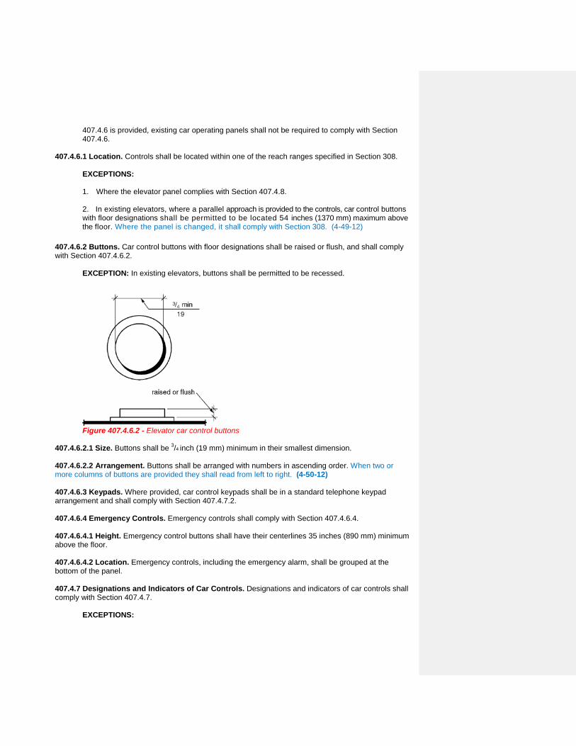
407.4.6.2 Buttons. Car control buttons with floor designations shall be raised or flush, and shall comply with Section 407.4.6.2.
EXCEPTION: In existing elevators, buttons shall be permitted to be recessed.
Figure 407.4.6.2 - Elevator car control buttons
407.4.6.2.1 Size. Buttons shall be 3/4 inch (19 mm) minimum in their smallest dimension. 407.4.6.2.2 Arrangement. Buttons shall be arranged with numbers in ascending order. When two or more columns of buttons are provided they shall read from left to right. (4-50-12) 407.4.6.3 Keypads. Where provided, car control keypads shall be in a standard telephone keypad arrangement and shall comply with Section 407.4.7.2.
407.4.6.4 Emergency Controls. Emergency controls shall comply with Section 407.4.6.4. 407.4.6.4.1 Height. Emergency control buttons shall have their centerlines 35 inches (890 mm) minimum above the floor.
407.4.6.4.2 Location. Emergency controls, including the emergency alarm, shall be grouped at the bottom of the panel.
407.4.7 Designations and Indicators of Car Controls. Designations and indicators of car controls shall comply with Section 407.4.7.
EXCEPTIONS:
1. In existing elevators, where a new car operating panel complying with Section 407.4.7 is
provided, existing car operating panels shall not be required to comply with Section 407.4.7.
2. Where existing building floor designations differ from the arrangement required by Section 407.4.6.2.2, or are alphanumeric, a new operating panel shall be permitted to use such existing building floor designations.
407.4.7.1 Buttons. Car control buttons shall comply with Section 407.4.7.1.
407.4.7.1.1 Type. Control buttons shall be identified by raised characters and braille complying with Sections 703.3 and 703.4.
407.4.7.1.2 Designation. Floors shall be designated . . . -4, -3, -2, -1, 0, 1, 2, 3, 4, etcetera, with floors below the main entry floor designated with minus numbers. Numbers shall be permitted to be omitted, provided the remaining numbers are in sequence. Where a telephone keypad arrangement is used, the number key (“#”) shall be utilized to enter the minus symbol (“-”). Ancillary letters shall be permitted to be used in conjunction with the numbers provided the letters are located to the right of the numbers and not more than two letters are used for each floor designation. (4-50-12) 407.4.7.1.3 Location. Raised character and braille designations shall be placed immediately to the left of the control button to which the designations apply. Where a negative number is used to indicate a negative floor, the braille designation shall be a cell with the dots 3 and 6 followed by the ordinal number.
EXCEPTION: Where space on an existing car operating panel precludes raised characters and braille to the left of the control button, markings shall be placed as near to the control button as possible.
407.4.7.1.4 Symbols. The control button for the emergency stop, alarm, door open, door close, main entry floor, and phone, shall be identified with raised symbols and braille as shown in Table 407.4.7.1.4.
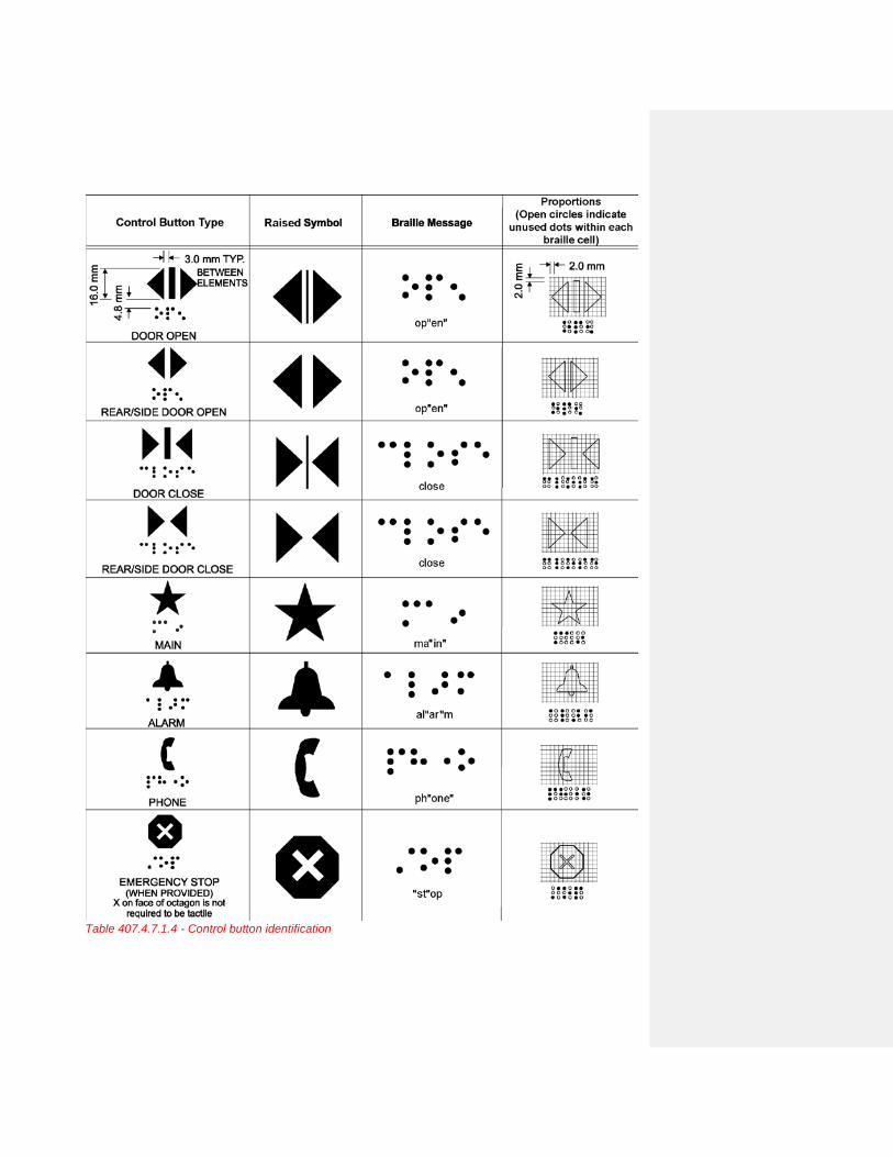
Table 407.4.7.1.4 - Control button identification
407.4.7.1.5 Visible Indicators. Buttons with floor designations shall be provided with visible indicators to show that a call has been registered. The visible indication shall extinguish when the car arrives at the designated floor.
407.4.7.2 Keypads. Keypad keys shall be identified by visual characters complying with Section 703.2 centered on the corresponding keypad button. The number five key shall have a single raised dot. The dot shall have a base diameter of 0.118 inch (3 mm) minimum and 0.120 inch (3.05 mm) maximum, and a height of 0.025 inch (0.6 mm) minimum and 0.037 inch (0.9 mm) maximum.
407.4.8 Elevator Car Call Sequential Step Scanning. Elevator car call sequential step scanning shall be provided where car control buttons are provided more than 48 inches (1220 mm) above the floor. Floor selection shall be accomplished by applying momentary or constant pressure to the up or down scan button. The up scan button shall sequentially select floors above the current floor. The down scan button shall sequentially select floors below the current floor. When pressure is removed from the up or down scan button for more than 2 seconds, the last floor selected shall be registered as a car call. The up and down scan button shall be located adjacent to or immediately above the emergency control buttons.
407.4.9 Car Position Indicators. Audible and visible car position indicators shall be provided in elevator cars.
407.4.9.1 Visible Indicators. Visible indicators shall comply with Section 407.4.9.1.
407.4.9.1.1 Size. Characters shall be 5/8 inch (16 mm) minimum in height. (4-53-12)
407.4.9.1.2 Location. Indicators shall be located above the car control panel or above the door.
407.4.9.1.3 Floor Arrival. As the car passes a floor and when a car stops at a floor served by the elevator, the corresponding character shall illuminate.
EXCEPTION: Destination-oriented elevators shall not be required to comply with Section 407.4.9.1.3, provided the visible indicators extinguish when the call has been answered.
407.4.9.1.4 Destination Indicator. In destination-oriented elevators, a display shall be provided in the car with visible indicators to show car destinations.
407.4.9.2 Audible Indicators. Audible indicators shall comply with Section 407.4.9.2.
407.4.9.2.1 Signal Type. The signal shall be an automatic verbal annunciator that announces the floor at which the car is about to stop. The verbal announcement indicating the floor shall be completed prior to the initiation of the door opening.
EXCEPTION: For elevators other than destination-oriented elevators that have a rated speed of 200 feet per minute (1 m/s) maximum, a non-verbal audible signal with a frequency of 1500 Hz maximum that sounds as the car passes or is about to stop at a floor served by the elevator shall be permitted.
407.4.9.2.2 Signal Level. The verbal annunciator shall be 10 dBA minimum above ambient, but shall not exceed 80 dBA, measured at the annunciator.
407.4.9.2.3 Frequency. The verbal annunciator shall have a frequency of 300 Hz minimum and 3,000 Hz maximum.
407.4.10 Emergency Communications. Emergency two-way communication systems between the elevator car and a point outside the hoistway shall comply with Section 407.4.10 and ASME A17.1/CSA B44 listed in Section 106.2.9. (4-54-12 PC1 through PC3)

407.4.10.1 Height. The highest operable part of a two-way communication system shall comply with Section 308.
407.4.10.2 Identification. Raised characters and braille complying with Sections 703.3 and 703.4 and raised symbols complying with Section 407.4.7.1.4 shall be provided adjacent to the device. 407.4.10.3 Instructions. Where instructions for use are provided, essential information shall be presented in visual form, raised characters and braille complying with Sections 703.2, 703.3 and 703.4. (4-55-12) 408 Limited-Use/Limited-Application Elevators 408.1 General. Limited-use/limited-application elevators shall comply with Section 408 and ASME A17.1/CSA B44 listed in Section 106.2.9. Elevator operation shall be automatic. 408.2 Elevator Landing Requirements. Landings serving limited-use/limited application elevators shall comply with Section 408.2.
408.2.1 Call Controls. Elevator call buttons and keypads shall comply with Section 407.2.1.
408.2.2 Hall Signals. Hall signals shall comply with Section 407.2.2.
408.2.3 Hoistway Signs. Signs at elevator hoistways shall comply with Section 407.2.3.
408.3 Elevator Door Requirements. Elevator hoistway doors shall comply with Section 408.3.
408.3.1 Sliding Doors. Sliding hoistway and car doors shall comply with Sections 407.3.1 through 407.3.3, and 408.3.3.
408.3.2 Swinging Doors. Swinging hoistway doors shall open and close automatically and shall comply with Sections 408.3.2, 404, and 407.3.2.
408.3.2.1 Power Operation. Swinging doors shall be power-operated and shall comply with BHMA A156.19 listed in Section 106.2.7
408.3.2.2 Duration. Power-operated swinging doors shall remain open for 20 seconds minimum when activated.
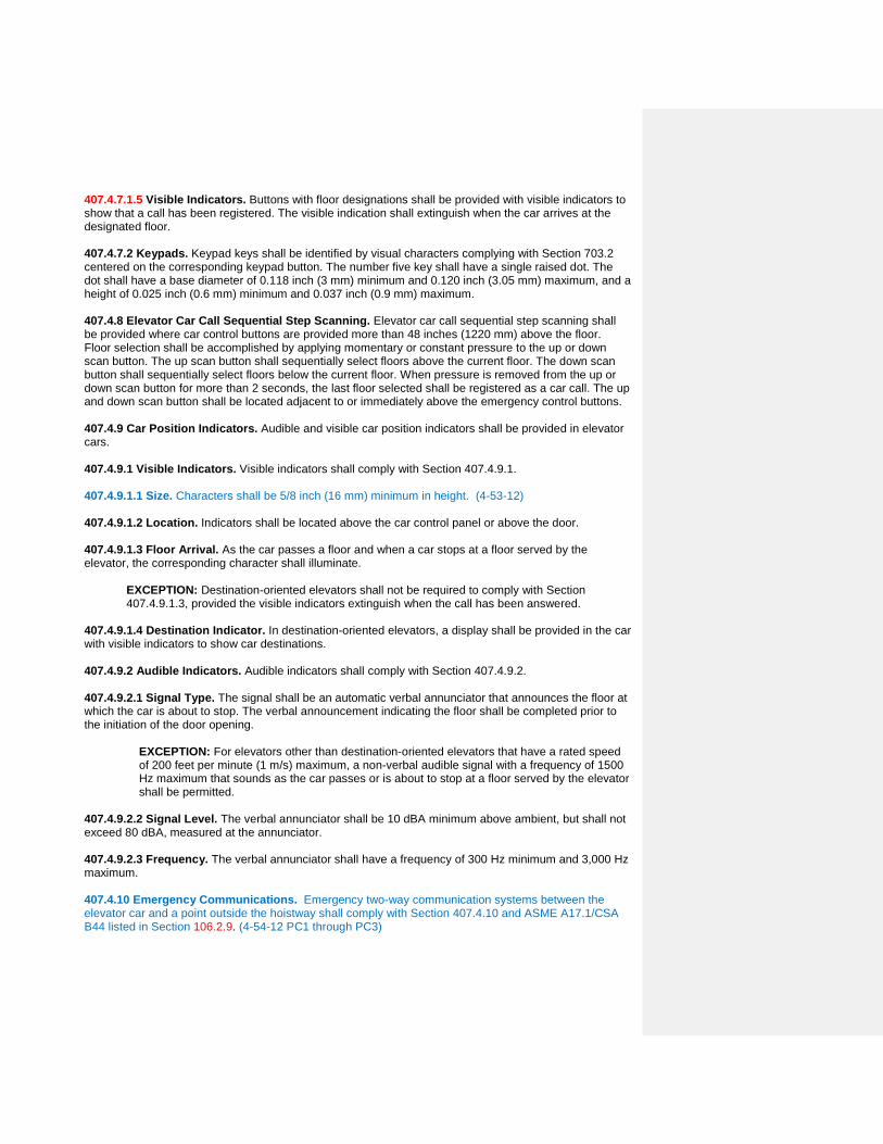
408.3.3 Door Location and Width. Car doors shall comply with Section 408.3.3. Figure 408.3.3 (a) thru (d) - Door location for limited use/limited application (LULA) elevators
a) car with single door
b) car with doors on opposite sides
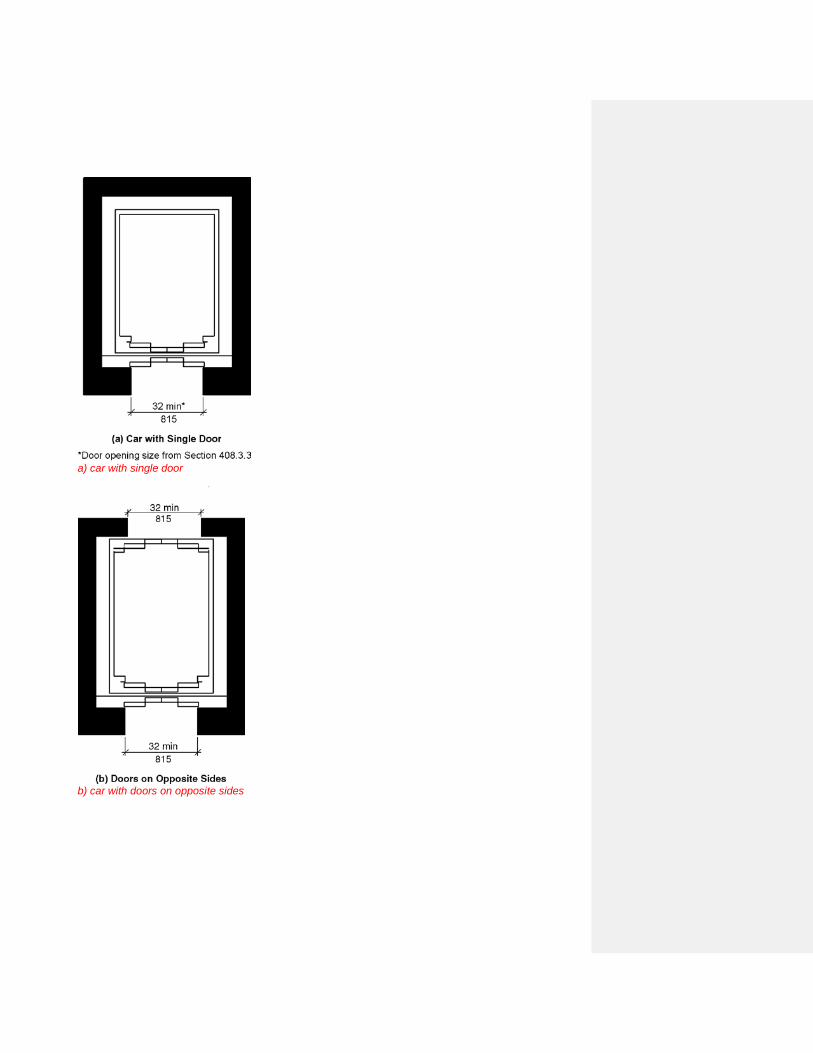
c) car with doors on adjacent sides
d) car with doors on adjacent sides - exception 408.3.3.1 Cars with Single Door or Doors on Opposite Ends. Car doors shall be positioned at the narrow end of cars with a single door and on cars with doors on opposite ends. Doors shall provide a clear opening width of 32 inches (815 mm) minimum.
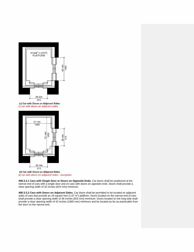
408.3.3.2 Cars with Doors on Adjacent Sides. Car doors shall be permitted to be located on adjacent sides of cars that provide an 18 square foot (1.67 m2) platform. Doors located on the narrow end of cars shall provide a clear opening width of 36 inches (815 mm) minimum. Doors located on the long side shall provide a clear opening width of 42 inches (1065 mm) minimum and be located as far as practicable from the door on the narrow end.
EXCEPTION: Car doors that provide a clear opening width of 36 inches (915 mm) minimum shall be permitted to be located on adjacent sides of cars that provide a clear floor area of 51 inches (1295 mm) in width and 51 inches (1295 mm) in depth.
408.4 Elevator Car Requirements. Elevator cars shall comply with Section 408.4.
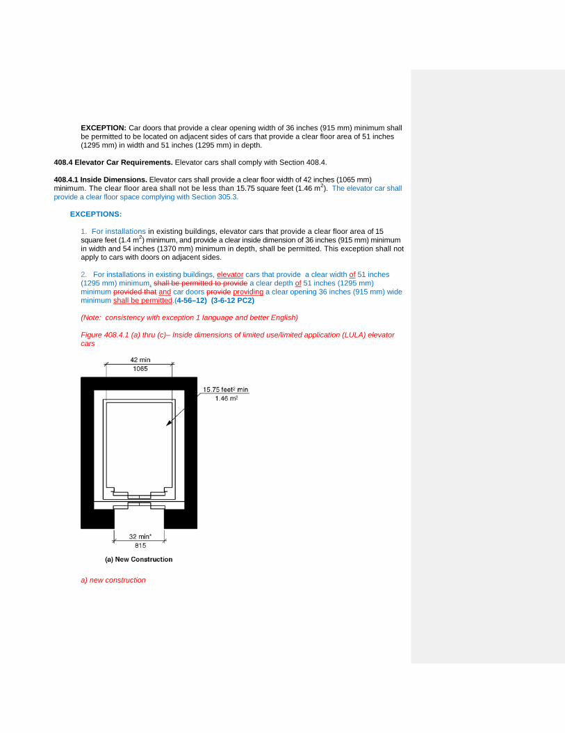
408.4.1 Inside Dimensions. Elevator cars shall provide a clear floor width of 42 inches (1065 mm) minimum. The clear floor area shall not be less than 15.75 square feet (1.46 m2). The elevator car shall provide a clear floor space complying with Section 305.3.
EXCEPTIONS:
1. For installations in existing buildings, elevator cars that provide a clear floor area of 15 square feet (1.4 m2) minimum, and provide a clear inside dimension of 36 inches (915 mm) minimum in width and 54 inches (1370 mm) minimum in depth, shall be permitted. This exception shall not apply to cars with doors on adjacent sides.
2. For installations in existing buildings, elevator cars that provide a clear width of 51 inches (1295 mm) minimum, shall be permitted to provide a clear depth of 51 inches (1295 mm) minimum provided that and car doors provide providing a clear opening 36 inches (915 mm) wide minimum shall be permitted.(4-56–12) (3-6-12 PC2) (Note: consistency with exception 1 language and better English) Figure 408.4.1 (a) thru (c)– Inside dimensions of limited use/limited application (LULA) elevator cars
a) new construction
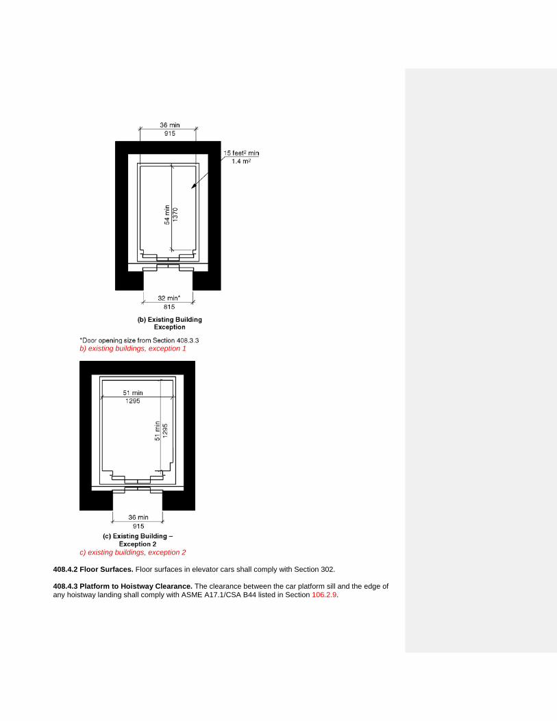
b) existing buildings, exception 1
c) existing buildings, exception 2
408.4.2 Floor Surfaces. Floor surfaces in elevator cars shall comply with Section 302.
408.4.3 Platform to Hoistway Clearance. The clearance between the car platform sill and the edge of any hoistway landing shall comply with ASME A17.1/CSA B44 listed in Section 106.2.9.
408.4.4 Leveling. Elevator car leveling shall comply with Section 407.4.4.
408.4.5 Illumination. Elevator car illumination shall comply with Section 407.4.5.
408.4.6 Elevator Car Controls. Elevator car controls shall comply with Section 407.4.6. Control panels shall be centered on a side wall.
408.4.7 Designations and Indicators of Car Controls. Designations and indicators of car controls shall comply with Section 407.4.7.
408.4.8 Emergency Communications. Car emergency signaling devices complying with Section 407.4.10 shall be provided.
409 Private Residence Elevators
409.1 General. Private residence elevators shall comply with Section 409 and ASME A17.1/CSA B44 listed in Section 106.2.9. Elevator operation shall be automatic.
EXCEPTION: Elevators complying with Section 407 or 408 shall not be required to comply with Section 409.
409.2 Call Controls. Call buttons at elevator landings shall comply with Section 309. Call buttons shall be 3/4 inch (19 mm) minimum in their smallest dimension. 409.3 Doors and Gates. Elevator car and hoistway doors and gates shall comply with Sections 409.3 and 404.
EXCEPTION: The maneuvering clearances required by Section 404.2.3 shall not apply for approaches to the push side of swinging doors.
409.3.1 Power Operation. Elevator car doors and gates shall be power operated and shall comply with BHMA A156.19 listed in Section 106.2.7. Elevator cars with a single opening shall have low energy power operated hoistway doors and gates.
EXCEPTION: Hoistway doors or gates shall be permitted to be of the self-closing, manual type, where that door or gate provides access to a narrow end of the car that serves only one landing.
409.3.2 Duration. Power operated doors and gates shall remain open for 20 seconds minimum when activated.
409.3.3 Door or Gate Location and Width. Car gates or doors positioned at a narrow end of the clear floor area required by Section 409.4.1 shall provide a clear opening width of 32 inches (815 mm) minimum. Car gates or doors positioned on adjacent sides shall provide a clear opening width of 42 inches (1065 mm) minimum. 409.4 Elevator Car Requirements. Elevator cars shall comply with Section 409.4.
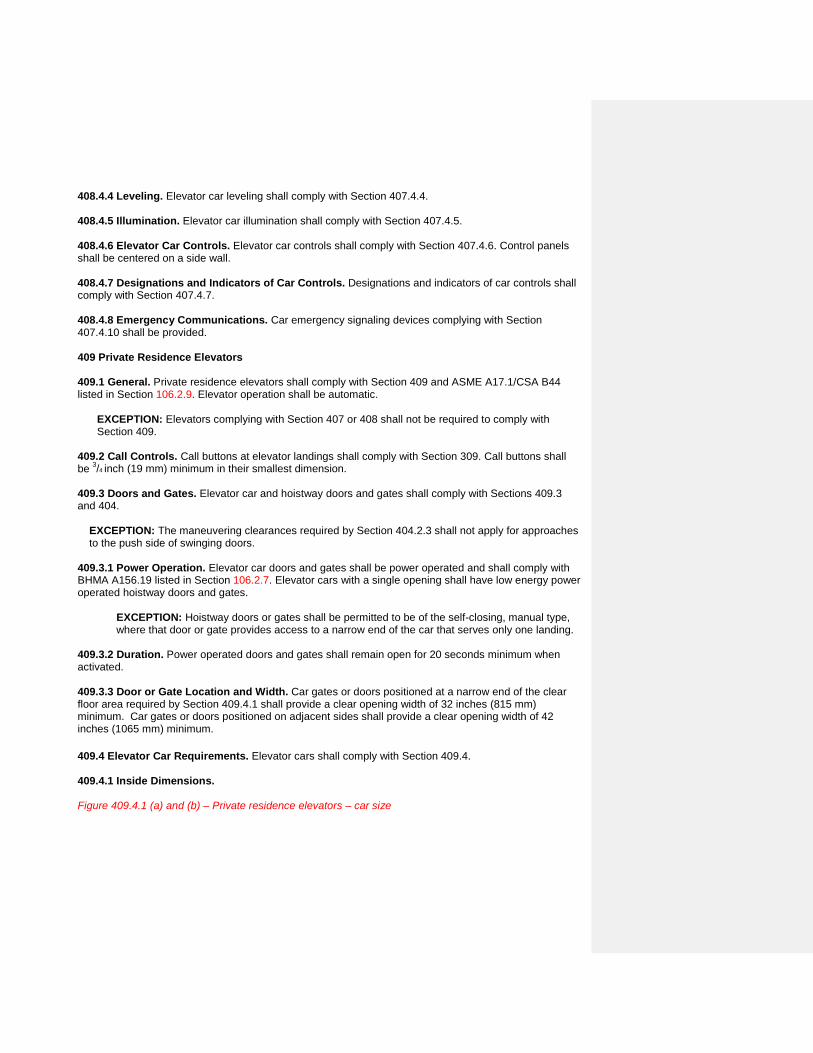
409.4.1 Inside Dimensions. Figure 409.4.1 (a) and (b) – Private residence elevators – car size
a) new buildings
b) existing buildings 409.4.1.1 New buildings. In new buildings, elevator cars shall provide a clear floor area 36 inches (915 mm) minimum in width and 52 inches (1322 mm) minimum in depth. (3-13B-12)
409.4.1.2 Existing buildings and within new Type B units. In existing buildings and within new Type B units, elevator cars shall provide a clear floor area 36 inches (915 mm) minimum in width and 48 inches (1220 mm) minimum in depth. (3-6-12 PC2) (Note: Already addressed for Type B in 1104.7) 409.4.2 Floor Surfaces. Floor surfaces in elevator cars shall comply with Section 302. 409.4.3 Platform to Hoistway Clearance. The clearance between the car platform sill and the edge of any hoistway landing shall be 11/4 inches (32 mm) maximum. 409.4.4 Leveling. Each car shall automatically stop at a floor landing within a tolerance of 1/2 inch (13 mm) under rated loading to zero loading conditions.
409.4.5 Illumination. The level of illumination at the car controls, platform, and car threshold and landing sill shall be 5 foot-candles (54 lux) minimum. 409.4.6 Elevator Car Controls. Elevator car controls shall comply with Sections 409.4.6 and 309.4.
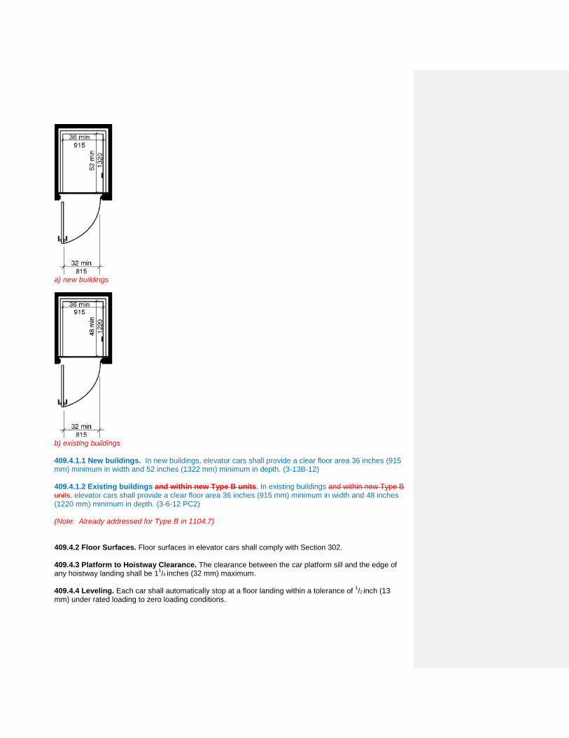
409.4.6.1 Buttons. Control buttons shall be 3/4 inch (19 mm) minimum in their smallest dimension. Control buttons shall be raised or flush. 409.4.6.2 Height. Buttons with floor designations shall comply with Section 309.3. 409.4.6.3 Location. Controls shall be on a sidewall, 12 inches (305 mm) minimum from any adjacent wall.
Figure 409.4.6.3 - Location of controls in private residence elevators
409.4.7 Emergency Communications. Emergency communications systems shall comply with Section 409.4.7.
409.4.7.1 Type. A telephone and emergency signal device shall be provided in the car.
409.4.7.2 Operable Parts. The telephone and emergency signaling device shall comply with Section 309.3 and 309.4.
409.4.7.3 Compartment. If the device is in a closed compartment, the compartment door hardware shall comply with Section 309.
409.4.7.4 Cord. The telephone cord shall be 29 inches (735 mm) minimum in length.
410 Platform Lifts 410.1 General. Platform lifts shall comply with Section 410 and ASME A18.1 listed in Section 106.2.10. Platform lifts shall not be attendant operated and shall provide unassisted entry and exit from the lift. 410.2 Lift Entry. Lifts with doors or gates shall comply with Section 410.2.1. Lifts with ramps shall comply with Section 410.2.2.
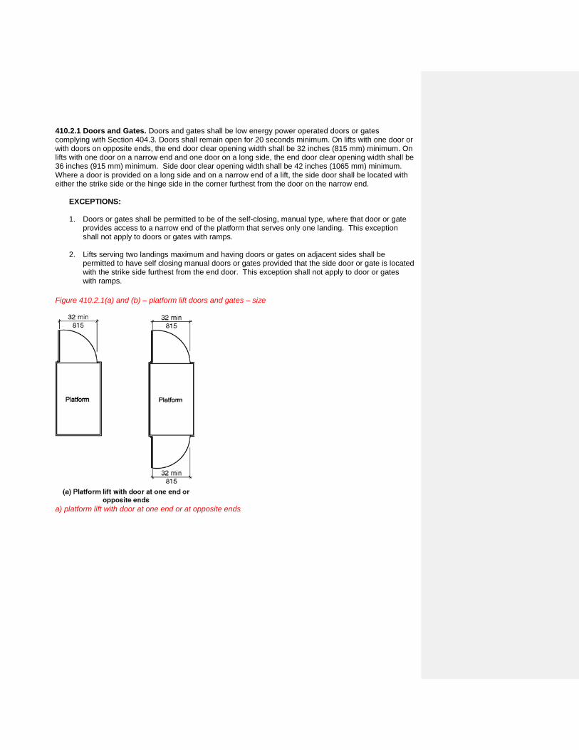
410.2.1 Doors and Gates. Doors and gates shall be low energy power operated doors or gates complying with Section 404.3. Doors shall remain open for 20 seconds minimum. On lifts with one door or with doors on opposite ends, the end door clear opening width shall be 32 inches (815 mm) minimum. On lifts with one door on a narrow end and one door on a long side, the end door clear opening width shall be 36 inches (915 mm) minimum. Side door clear opening width shall be 42 inches (1065 mm) minimum. Where a door is provided on a long side and on a narrow end of a lift, the side door shall be located with either the strike side or the hinge side in the corner furthest from the door on the narrow end.
EXCEPTIONS: 1. Doors or gates shall be permitted to be of the self-closing, manual type, where that door or gate
provides access to a narrow end of the platform that serves only one landing. This exception shall not apply to doors or gates with ramps.
2. Lifts serving two landings maximum and having doors or gates on adjacent sides shall be permitted to have self closing manual doors or gates provided that the side door or gate is located with the strike side furthest from the end door. This exception shall not apply to door or gates with ramps.
Figure 410.2.1(a) and (b) – platform lift doors and gates – size
a) platform lift with door at one end or at opposite ends
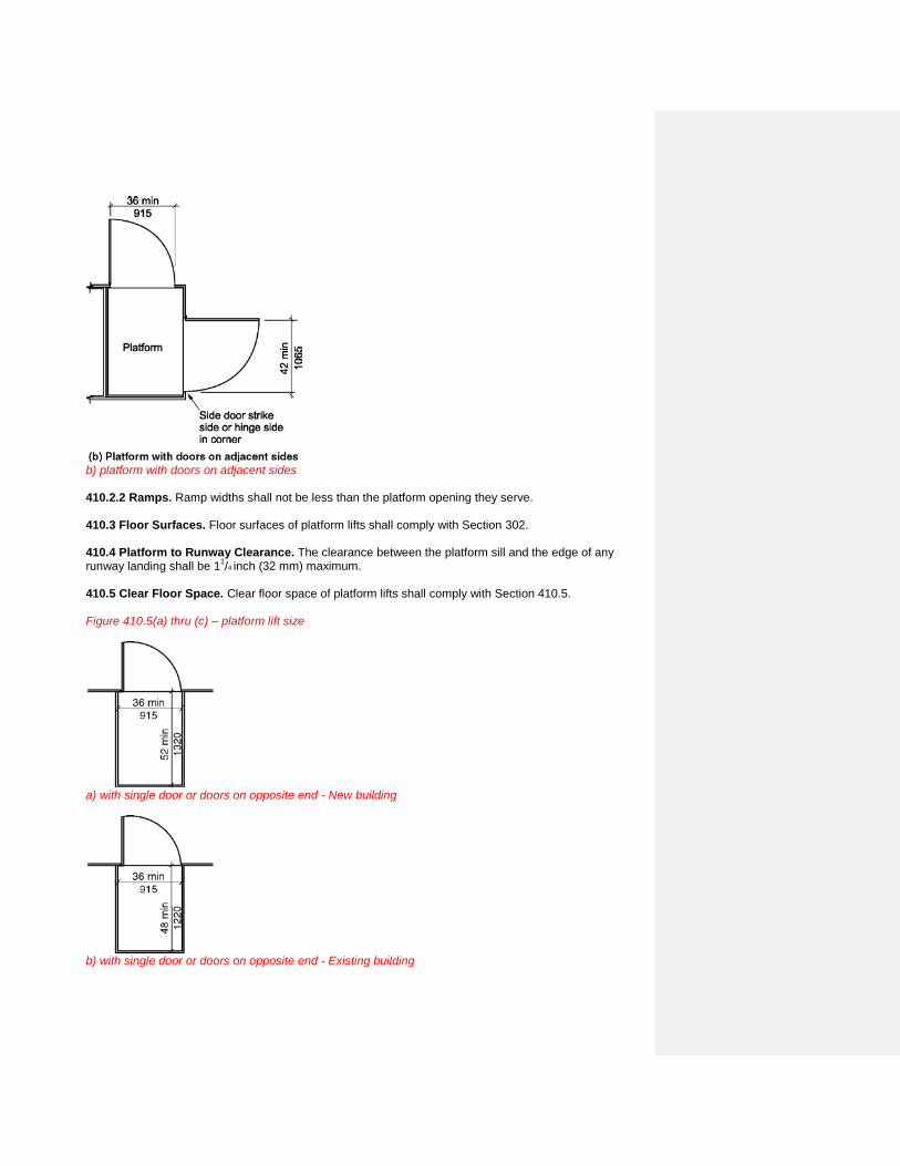
b) platform with doors on adjacent sides 410.2.2 Ramps. Ramp widths shall not be less than the platform opening they serve.
410.3 Floor Surfaces. Floor surfaces of platform lifts shall comply with Section 302. 410.4 Platform to Runway Clearance. The clearance between the platform sill and the edge of any runway landing shall be 11/4 inch (32 mm) maximum. 410.5 Clear Floor Space. Clear floor space of platform lifts shall comply with Section 410.5. Figure 410.5(a) thru (c) – platform lift size
a) with single door or doors on opposite end - New building
b) with single door or doors on opposite end - Existing building
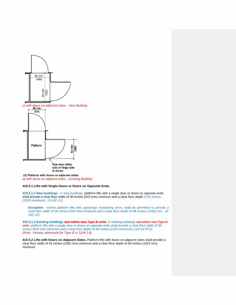
c) with doors on adjacent sides – New Building
d) with doors on adjacent sides – Existing Building 410.5.1 Lifts with Single Doors or Doors on Opposite Ends. 410.5.1.1 New buildings. In new buildings, platform lifts with a single door or doors on opposite ends shall provide a clear floor width of 36 inches (915 mm) minimum and a clear floor depth of 52 inches (1322 minimum). (3-13C-12)
Exception: Incline platform lifts with passenger restraining arms, shall be permitted to provide a clear floor width of 36 inches (915 mm) minimum and a clear floor depth of 48 inches (1220) mm. (3-13C-12)
410.5.1.2 Existing buildings and within new Type B units. In existing buildings and within new Type B units, platform lifts with a single door or doors on opposite ends shall provide a clear floor width of 36 inches (915 mm) minimum and a clear floor depth of 48 inches (1220 minimum). (3-6-12 PC2) (Note: Already addressed for Type B in 1104.1.8)
410.5.2 Lifts with Doors on Adjacent Sides. Platform lifts with doors on adjacent sides shall provide a clear floor width of 42 inches (1065 mm) minimum and a clear floor depth of 60 inches (1525 mm) minimum.

Exception: In existing buildings, platform lifts with doors on adjacent sides shall be permitted to provide a clear floor width of 36 inches (915 mm) and a clear floor depth of 60 inches (1525 mm).
410.6 Operable Parts. Controls for platform lifts shall comply with Section 309.