Embed Size (px)
DESCRIPTION
Chapter 4. The Motherboard. You Will Learn…. About the types of motherboards About components on the motherboard A basic procedure for building a computer How to install a motherboard How to troubleshoot a motherboard. Purpose of Motherboard. Houses the CPU - PowerPoint PPT Presentation
Citation preview
Chapter 4
The Motherboard
You Will Learn…• About the types of motherboards
• About components on the motherboard
• A basic procedure for building a computer
• How to install a motherboard
• How to troubleshoot a motherboard

Purpose of Motherboard• Houses the CPU
• Allows all devices to communicate with the CPU and with each other
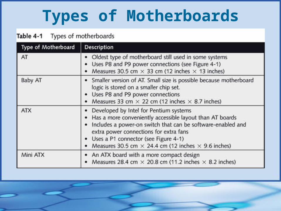
Types of Motherboards
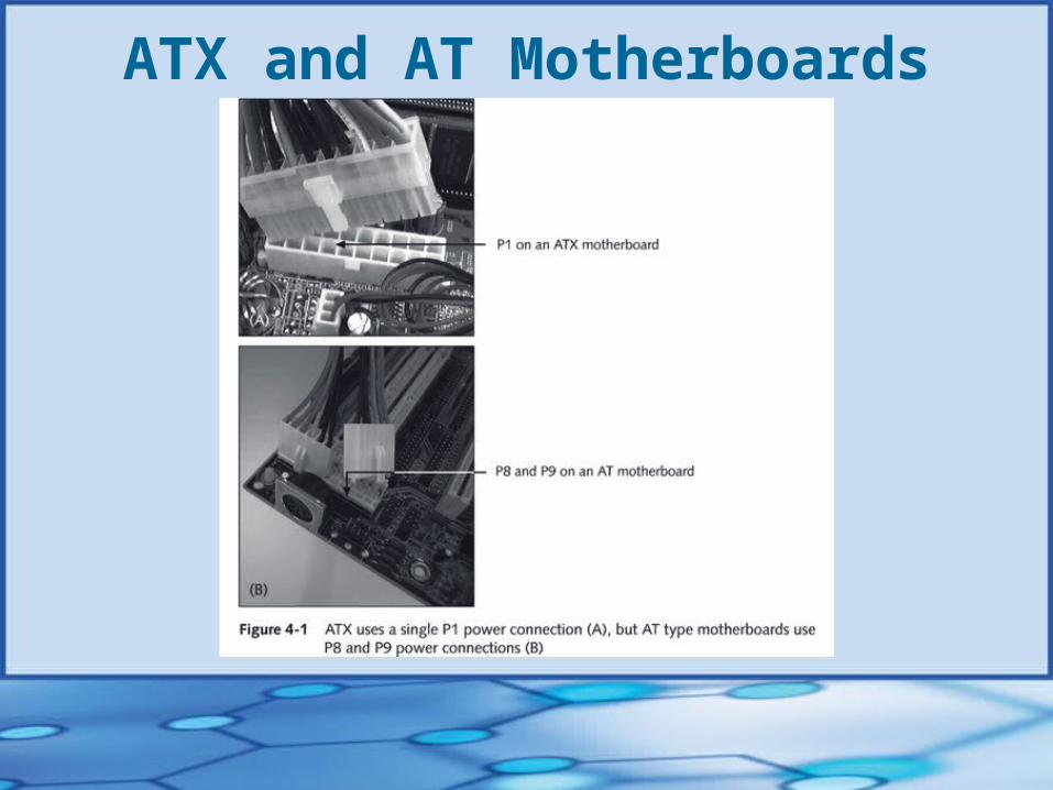
ATX and AT Motherboards
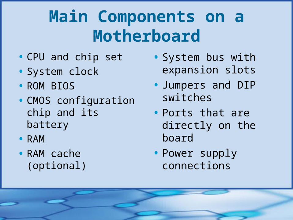
Main Components on a Motherboard
• CPU and chip set
• System clock
• ROM BIOS
• CMOS configuration chip and its battery
• RAM
• RAM cache (optional)
• System bus with expansion slots
• Jumpers and DIP switches
• Ports that are directly on the board
• Power supply connections
Field Replaceable Units (FRUs)• CPU
• ROM BIOS chip
• CMOS battery
• RAM
• RAM cache
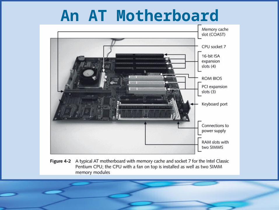
An AT Motherboard
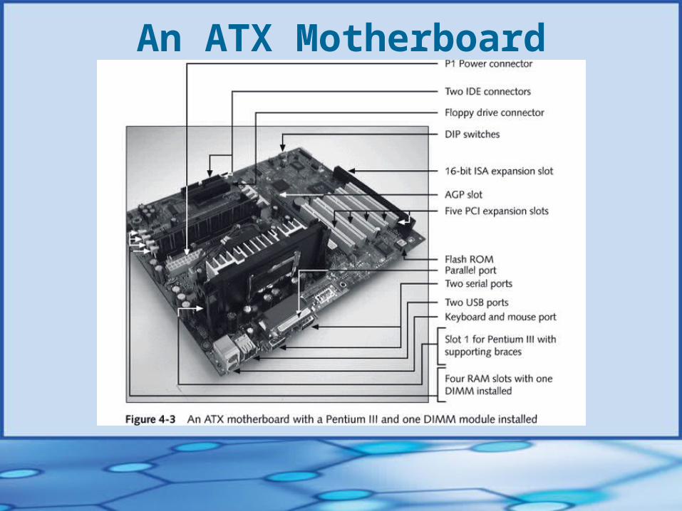
An ATX Motherboard
Components Determined by Motherboard Selection
• Types and speeds of CPU• Chip set on the board (already installed) • Memory cache and size• Types/number of expansion slots: ISA, PCI, AGP• Type of memory, including what kind and how much
SRAM and DRAM (SIMMs, DIMMs, or RIMMs)• Maximum amount of memory you can install;
incremental amounts by which you can upgrade
continued…
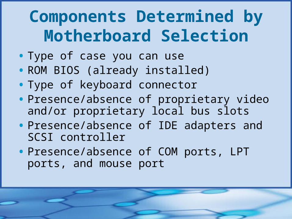
Components Determined by Motherboard Selection
• Type of case you can use• ROM BIOS (already installed)• Type of keyboard connector• Presence/absence of proprietary video and/or
proprietary local bus slots• Presence/absence of IDE adapters and SCSI controller• Presence/absence of COM ports, LPT ports, and
mouse port

Approaches to Selecting a Motherboard
1. Provides most room for expansion
2. Suits needs of current configuration
3. Meets present needs with moderate room for expansion
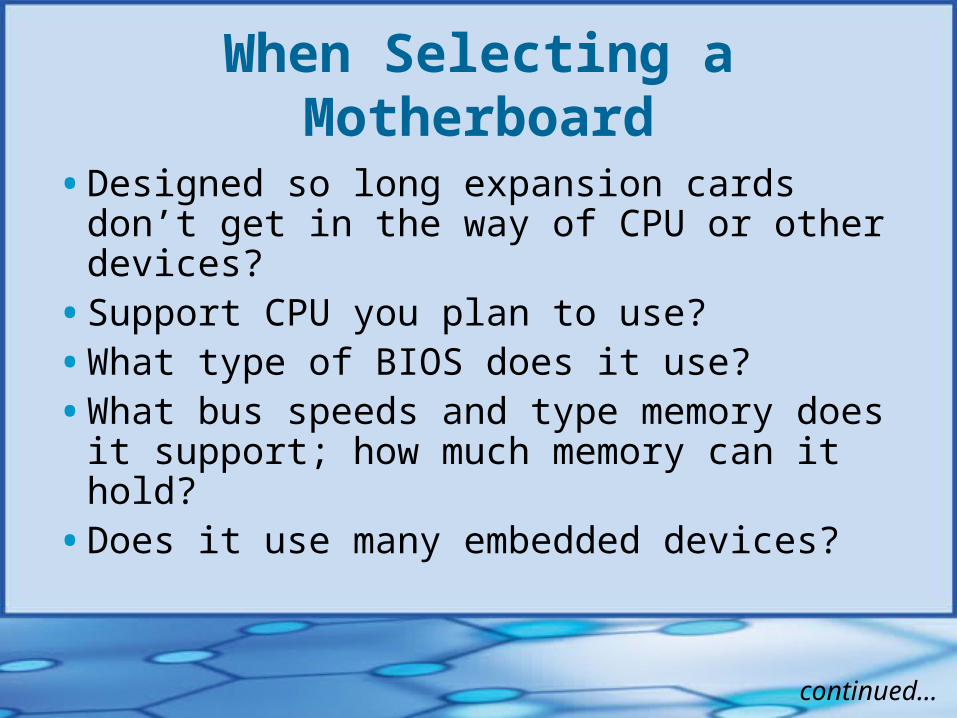
When Selecting a Motherboard• Designed so long expansion cards don’t get in
the way of CPU or other devices?
• Support CPU you plan to use?
• What type of BIOS does it use?
• What bus speeds and type memory does it support; how much memory can it hold?
• Does it use many embedded devices?
continued…
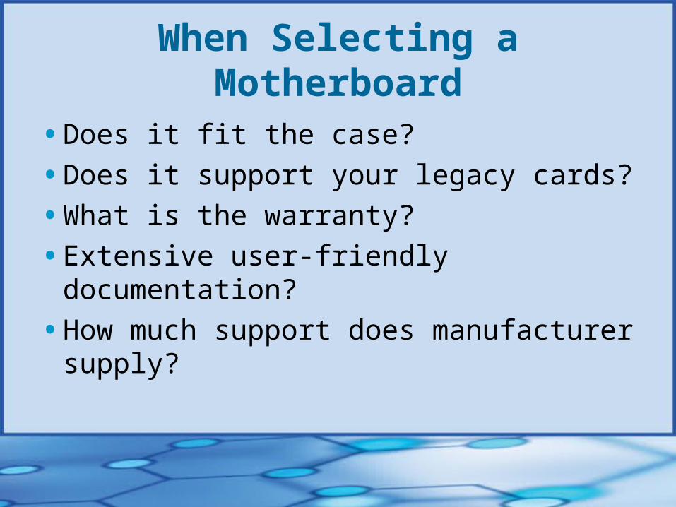
When Selecting a Motherboard• Does it fit the case?
• Does it support your legacy cards?
• What is the warranty?
• Extensive user-friendly documentation?
• How much support does manufacturer supply?
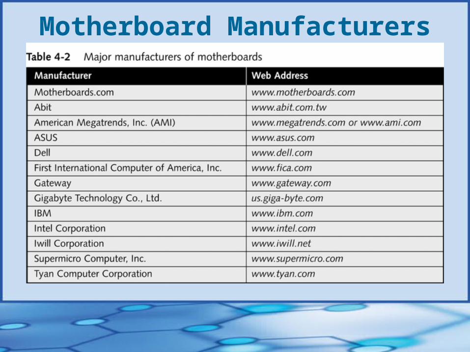
Motherboard Manufacturers
The System Clock• Keeps beat for motherboard activities
• Frequency measured in megahertz (MHz)
• Wait state Occurs when CPU must wait for another
component
CPU and Chip Set• IBM and IBM-compatible computers use a
microprocessor chip made by Intel or AMD, and to a lesser degree by Cyrix
Attributes Used to Rate CPUs• Speed (in gigahertz)
• Efficiency of programming code
• Number of transistors
• Number of registers
• Word size
• Data path
• Maximum number of memory addresses
• Amount of memory included
• Multiprocessing abilities
• Special functionality
The Pentium and Its Competitors• Pentium processor
A true multiprocessor (has two ALUs) 64-bit external path size and two 32-bit internal
paths (one for each ALU)
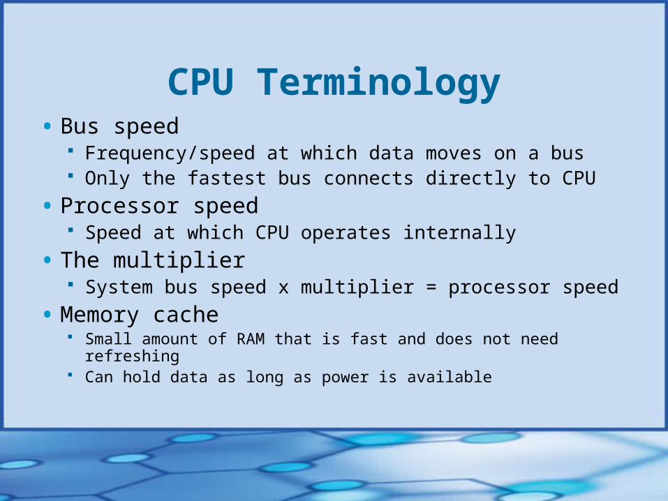
CPU Terminology• Bus speed
Frequency/speed at which data moves on a bus Only the fastest bus connects directly to CPU
• Processor speed Speed at which CPU operates internally
• The multiplier System bus speed x multiplier = processor speed
• Memory cache Small amount of RAM that is fast and does not need refreshing Can hold data as long as power is available
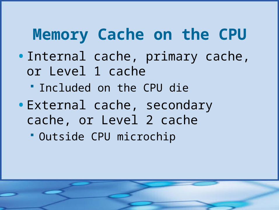
Memory Cache on the CPU• Internal cache, primary cache, or Level 1 cache
Included on the CPU die
• External cache, secondary cache, or Level 2 cache Outside CPU microchip
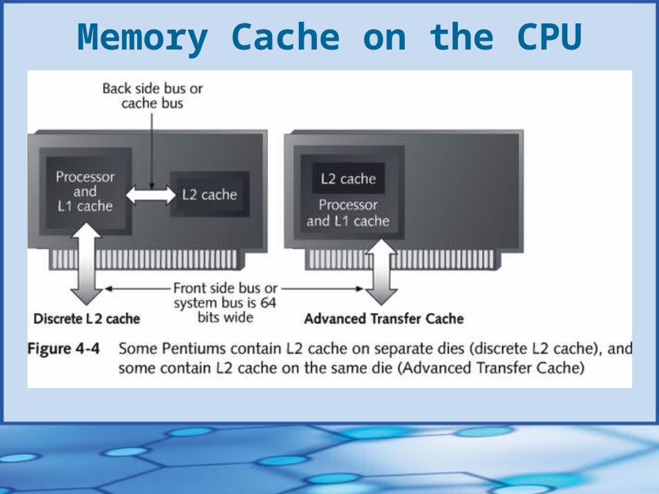
Memory Cache on the CPU
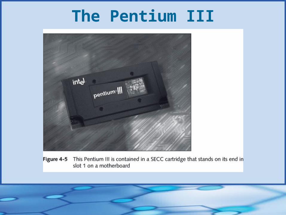
The Pentium III
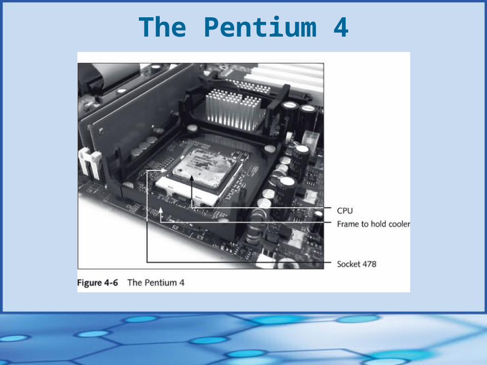
The Pentium 4
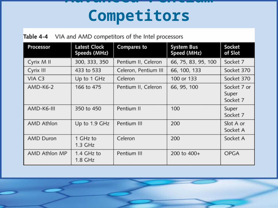
Advanced Pentium Competitors
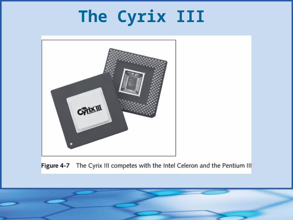
The Cyrix III
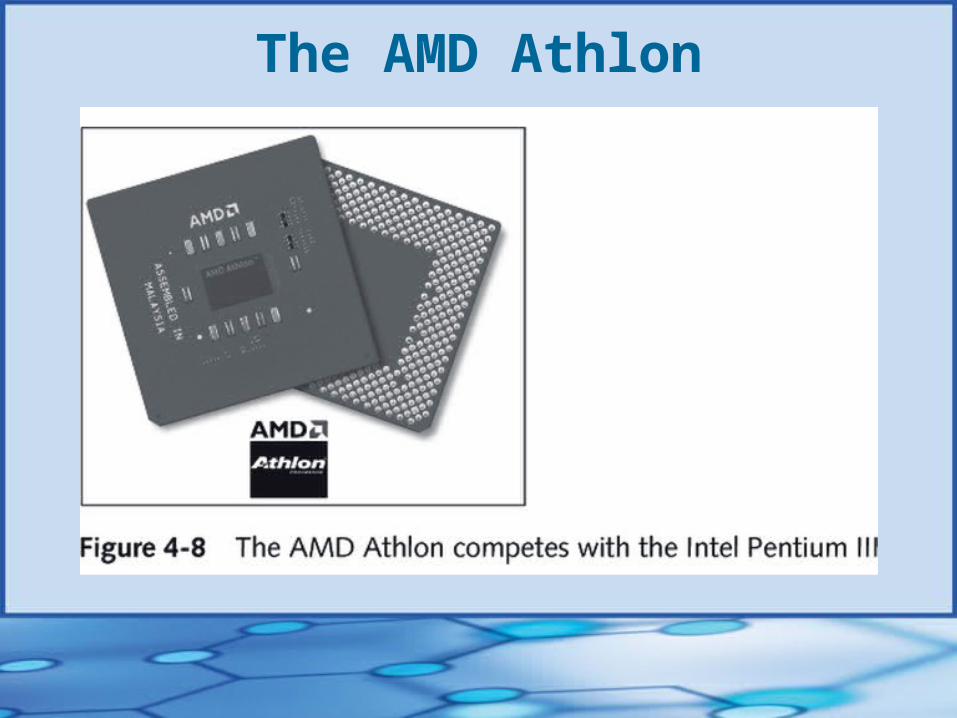
The AMD Athlon
Intel Itanium:The Next-Generation Processor
• Intel’s first 64-bit processor for microcomputers
• Designed for high-end enterprise servers
• Uses a new instruction set called the EPIC (explicitly parallel instruction computing) architecture
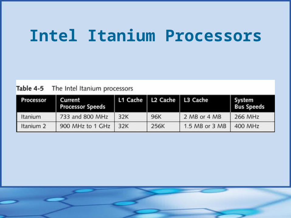
Intel Itanium Processors
CPU Heat Sinks & Cooling Fans• Heat sinks
Used by older CPUs to pull heat away from the CPU Clip-on device that mounts on top of the CPU
• Cooling fans Keep temperatures below the Intel maximum limit of
185 degrees F/85 degrees C
• Exotic options: refrigeration, peltiers, water coolers
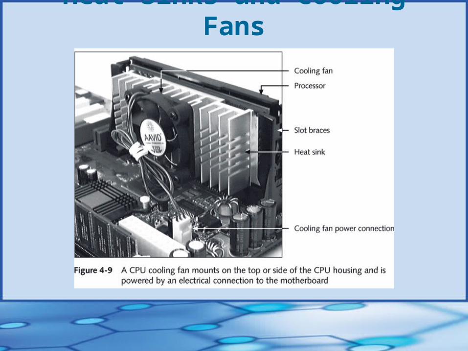
Heat Sinks and Cooling Fans
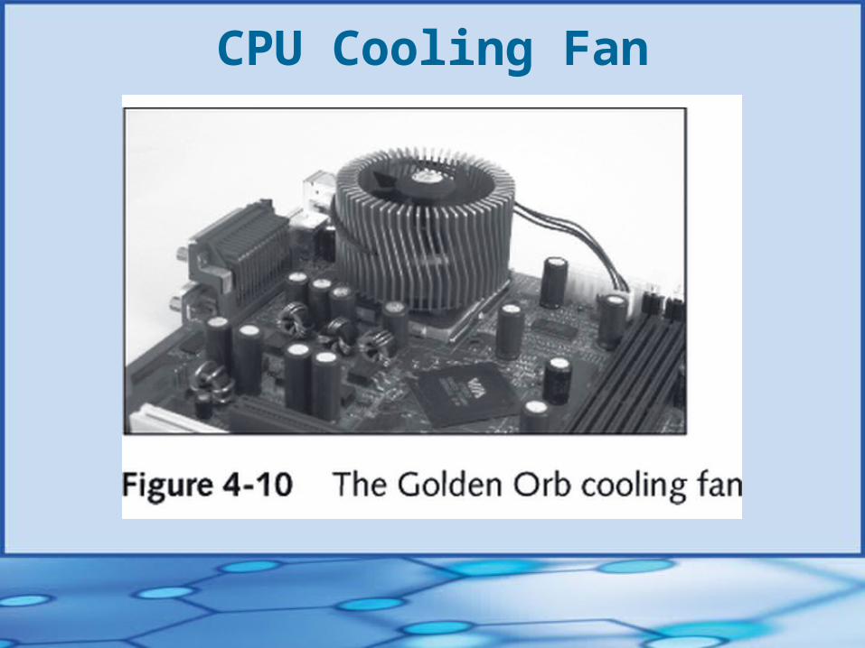
CPU Cooling Fan
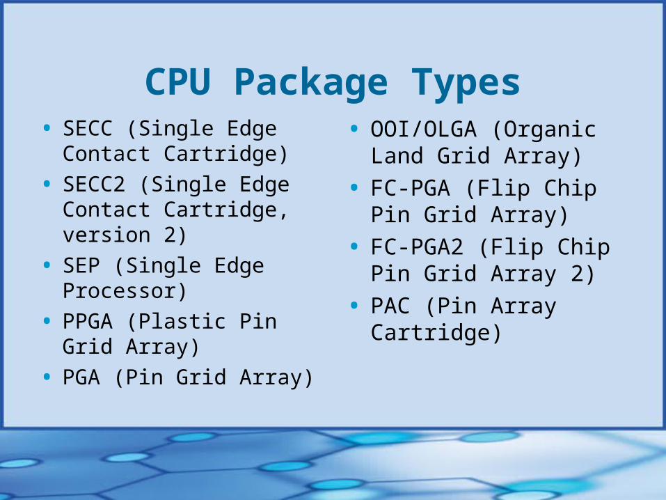
CPU Package Types• SECC (Single Edge Contact
Cartridge)
• SECC2 (Single Edge Contact Cartridge, version 2)
• SEP (Single Edge Processor)
• PPGA (Plastic Pin Grid Array)
• PGA (Pin Grid Array)
• OOI/OLGA (Organic Land Grid Array)
• FC-PGA (Flip Chip Pin Grid Array)
• FC-PGA2 (Flip Chip Pin Grid Array 2)
• PAC (Pin Array Cartridge)
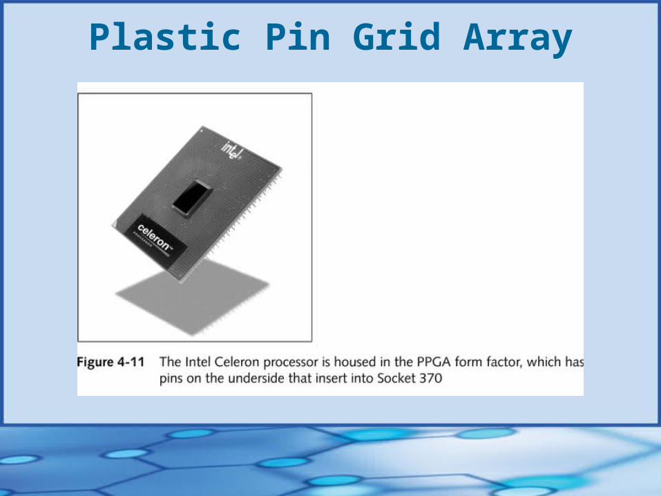
Plastic Pin Grid Array
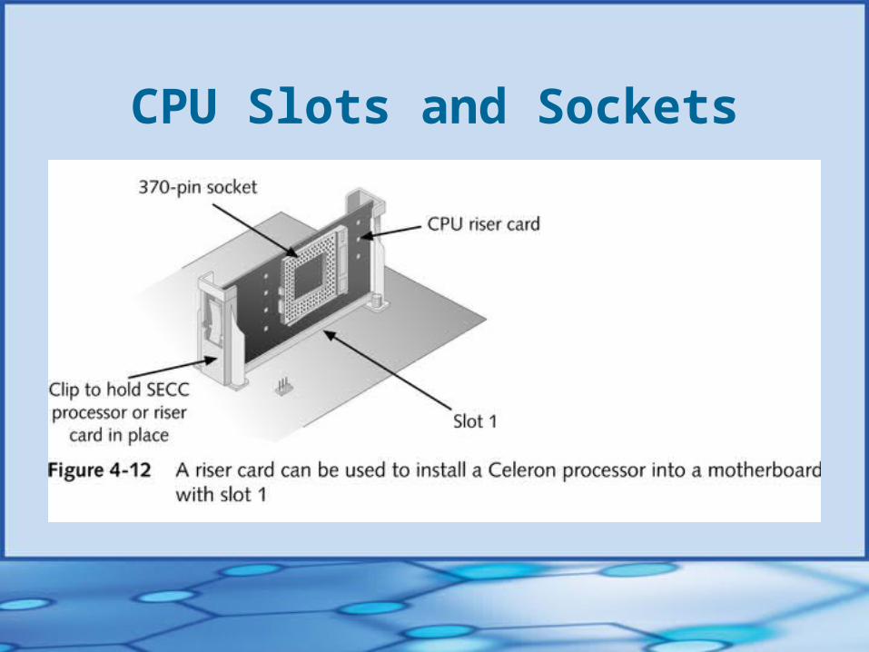
CPU Slots and Sockets• Physical connections used to connect CPU to
motherboard
• Motherboard and processor must match
• Slots 1 and 2 are proprietary Intel slots
• Slot A and Socket A are proprietary AMD connectors
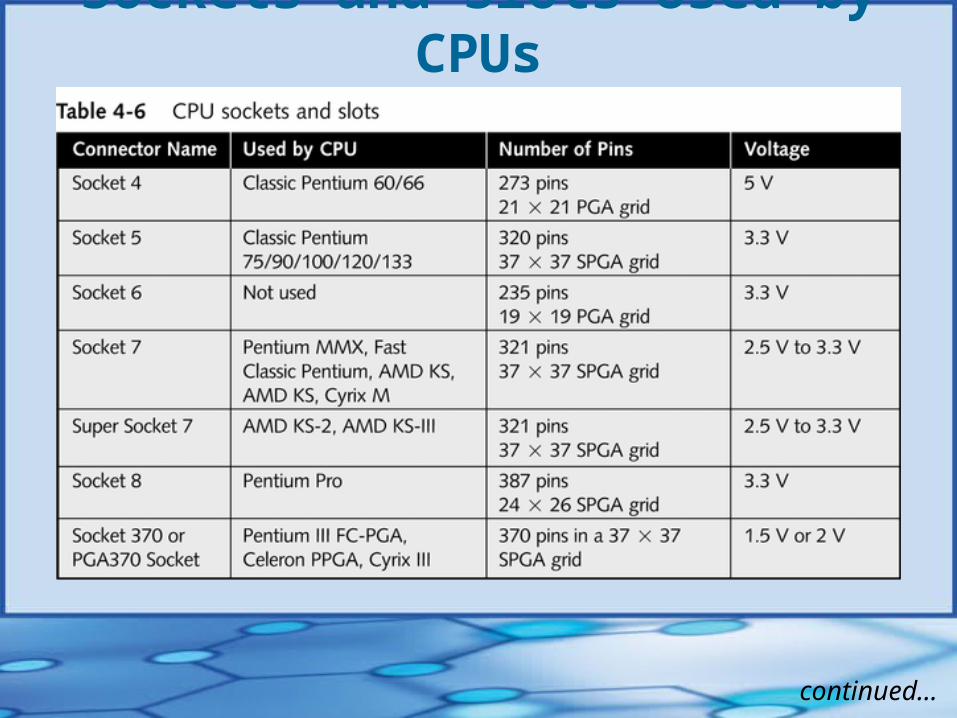
Sockets and Slots Used by CPUs
continued…
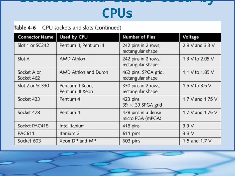
Sockets and Slots Used by CPUs
CPU Slots and Sockets• Earlier CPU sockets
Pin grid array (PGA) sockets Staggered pin grid array (SPGA) Low insertion force (LIF) sockets
• Current CPU sockets Zero insertion force (ZIF) sockets; small lever on
side of socket lifts CPU up and out of socket
CPU Slots and Sockets

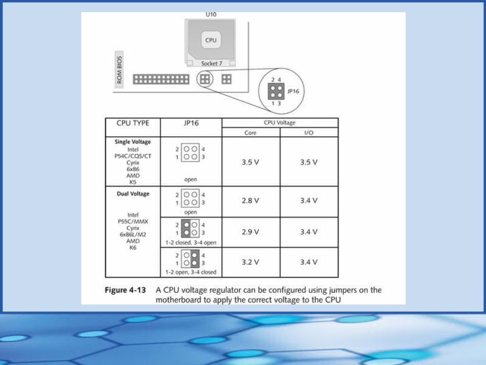
CPU Voltage Regulator• Controls the amount of voltage to the CPU
• Dual-voltage CPUs and single-voltage CPUs
The Chip Set• Set of chips on system board that collectively
controls memory cache, external buses, and some peripherals
• Intel dominates the market Most compatible with Pentium family of CPUs Investment in R&D has led to other developments
(eg, PCI bus, universal serial bus, AGP, and Accelerated Hub Architecture)
Intel Chip Sets• “E” chipset family
• Intel i800 Series
• Orion
• Natoma
• Triton III
• Triton II
• Triton I
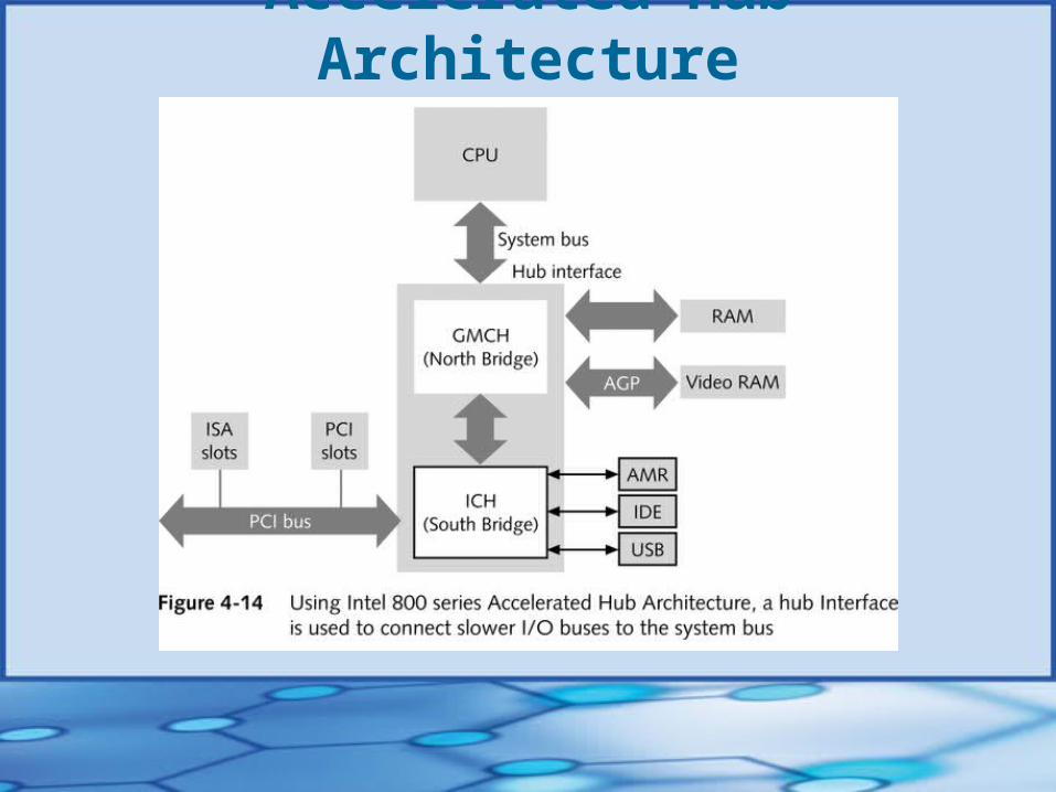
Accelerated Hub Architecture
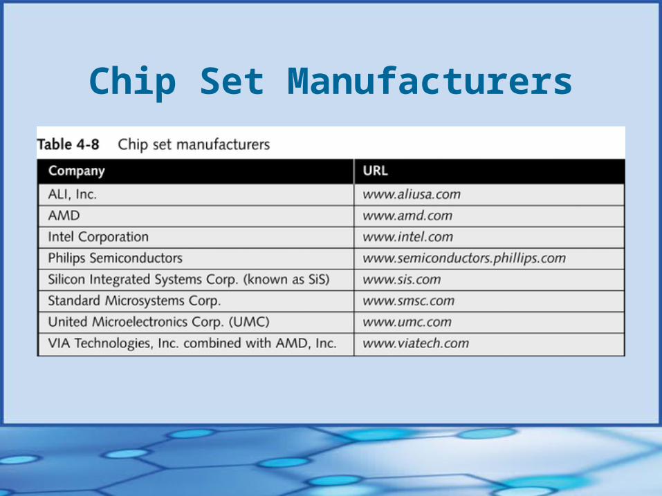
Chip Set Manufacturers
ROM BIOS• One ROM chip on motherboard contains BIOS
BIOS manages startup process (startup BIOS) and basic I/O functions (system BIOS)
• Most devices are not supported by system BIOS, but by device drivers
• Flash ROM (erasable programmable read-only memory or EEPROM) allows ROM BIOS to be upgraded without changing ROM chip
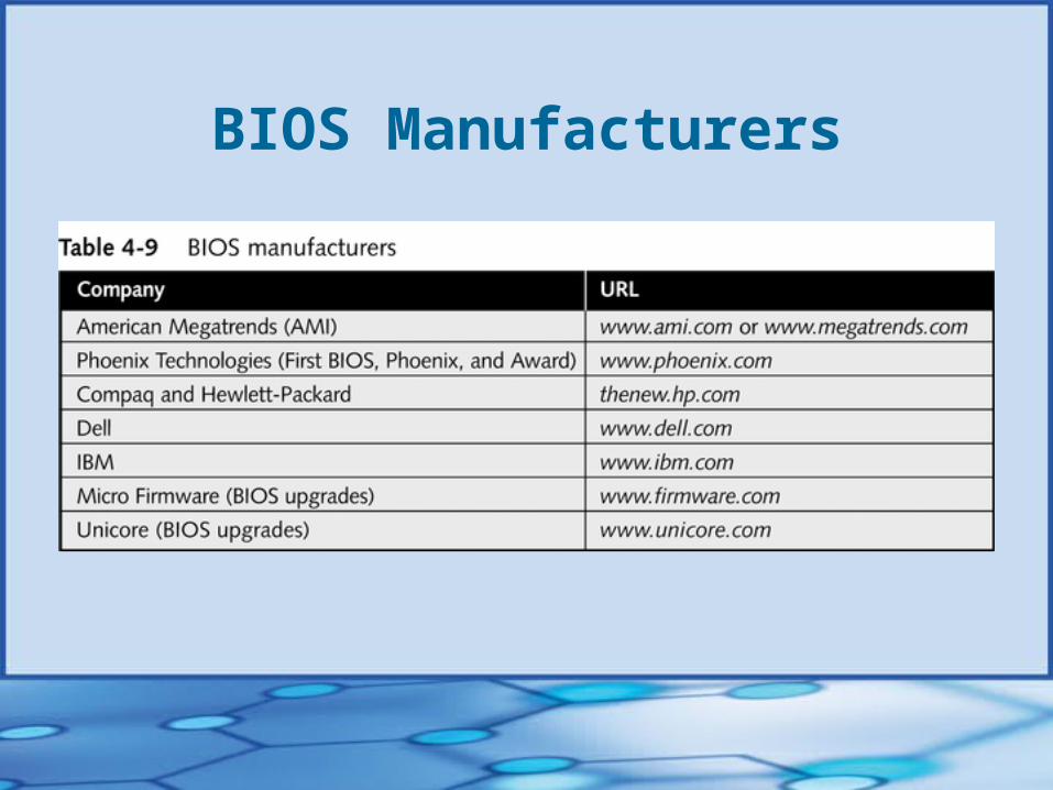
BIOS Manufacturers
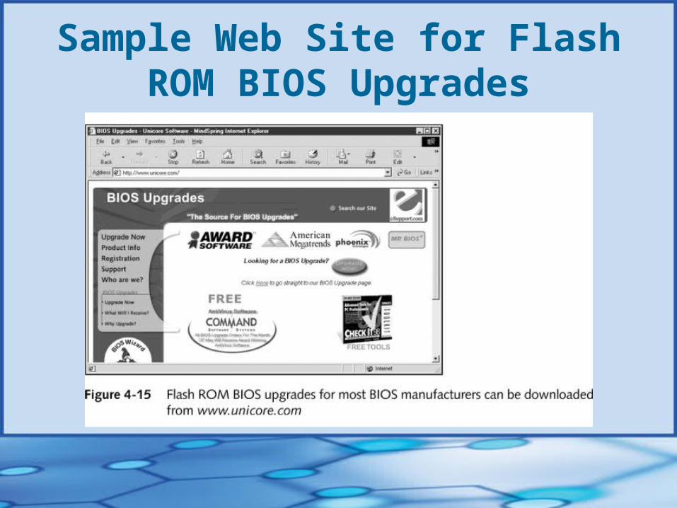
Sample Web Site for Flash ROM BIOS Upgrades
Buses and Expansion Slots• PCs have four or five buses, each with different
speeds, access methods, and protocols• Buses evolved around data path and speed• So many buses because single speed is not practical• Buses carry electrical power, control signals, memory
addresses, and data• On-board ports (eg, keyboard port and mouse port)• Expansion slots can be located on motherboard;
sometimes stacked vertically on a second board

Buses Listed by Throughput
Relationship of CPU Speedto Bus Speed
• Overall performance is better when multiplier is small
• Change speed of a computer by: Changing speed of system bus, or Changing multiplier that determines speed of CPU
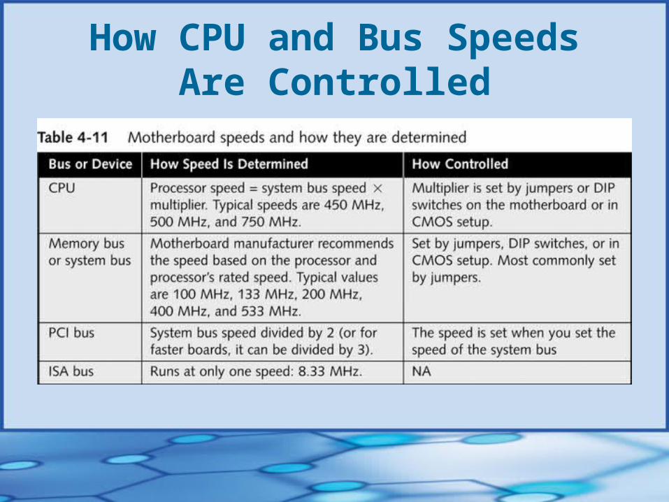
How CPU and Bus SpeedsAre Controlled
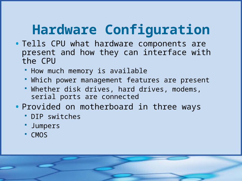
Hardware Configuration• Tells CPU what hardware components are present and
how they can interface with the CPU How much memory is available Which power management features are present Whether disk drives, hard drives, modems, serial ports are
connected
• Provided on motherboard in three ways DIP switches Jumpers CMOS
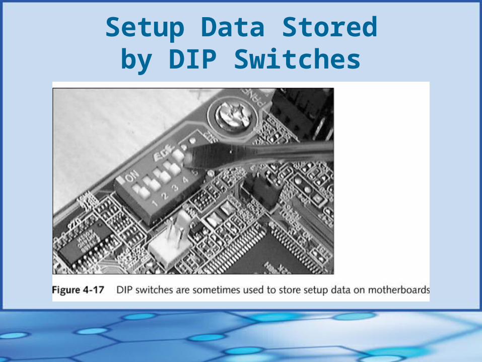
Setup Data Storedby DIP Switches

Setup Data Stored by Jumpers
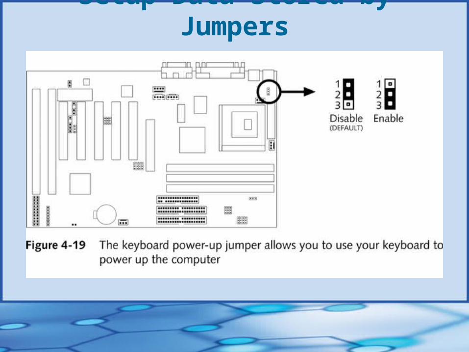
Setup Data Stored by Jumpers
Setup Data on a CMOS Chip• Also called real-time clock/nonvolatile RAM
(RTC/NVRAM) chip
• Retains data even when computer is turned off
• Requires very little electricity to hold data
• Setup cannot be changed unintentionally, but disk drive must be working before you can change the setup
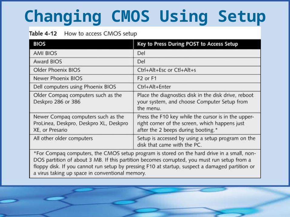
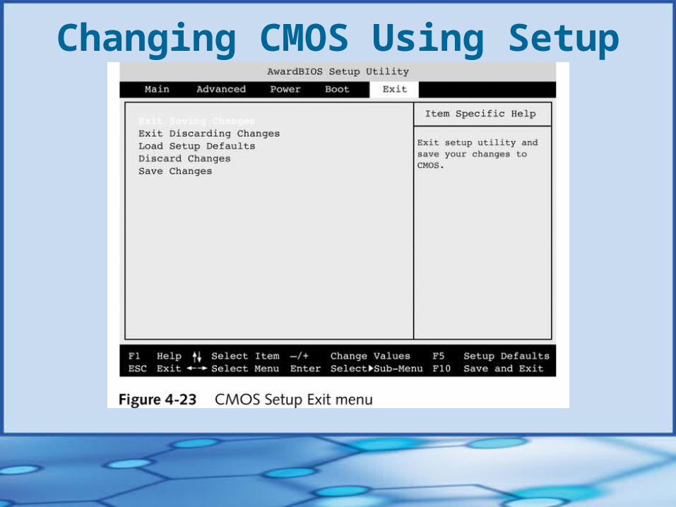
Changing CMOS Using Setup
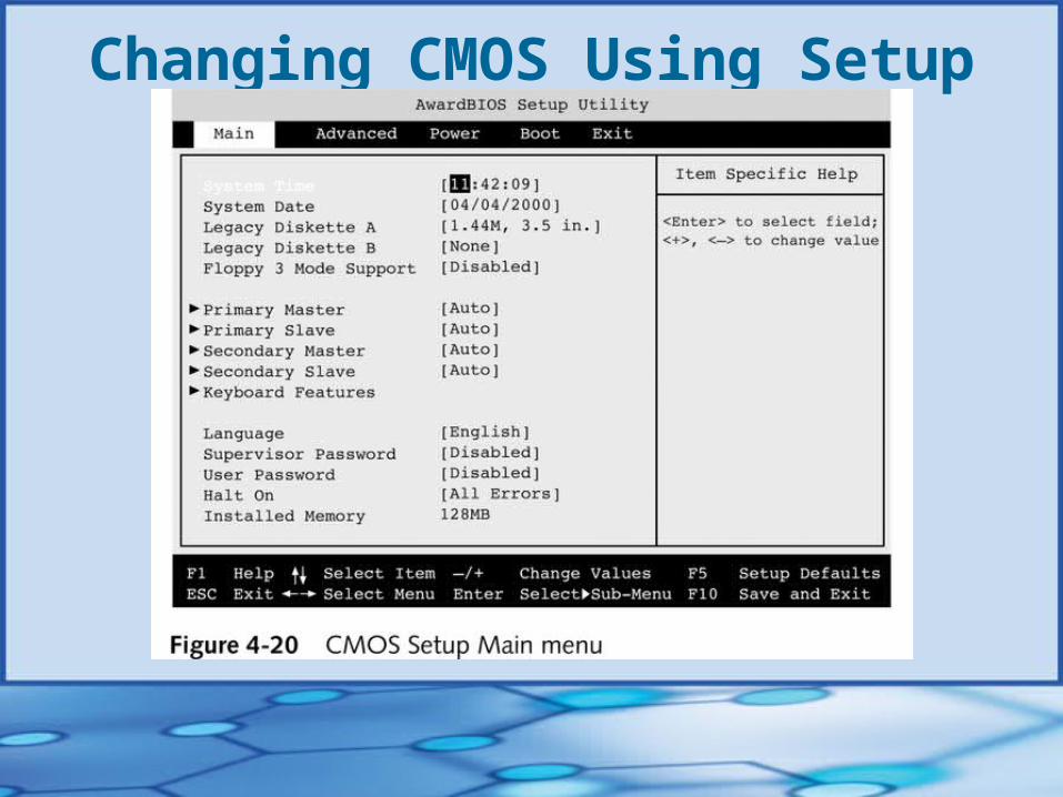
Changing CMOS Using Setup
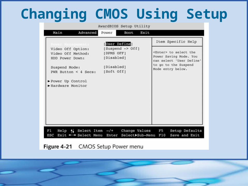
Changing CMOS Using Setup
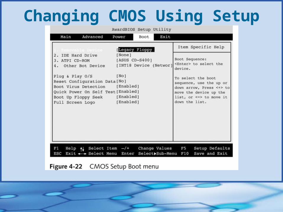
Changing CMOS Using Setup
Changing CMOS Using Setup

Battery Power to CMOS Chip
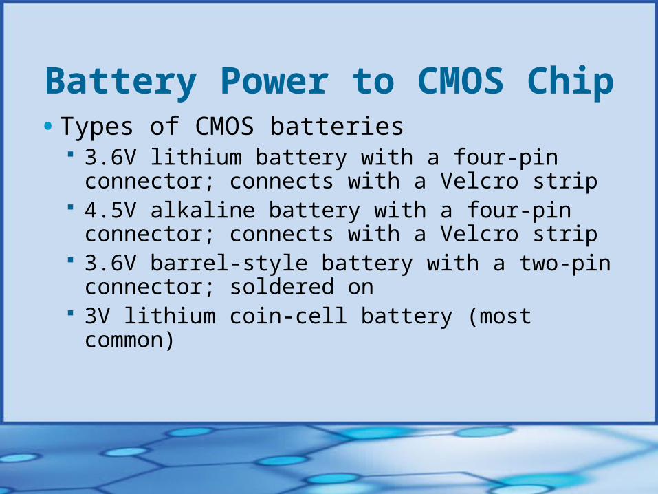
Battery Power to CMOS Chip• Types of CMOS batteries
3.6V lithium battery with a four-pin connector; connects with a Velcro strip
4.5V alkaline battery with a four-pin connector; connects with a Velcro strip
3.6V barrel-style battery with a two-pin connector; soldered on
3V lithium coin-cell battery (most common)
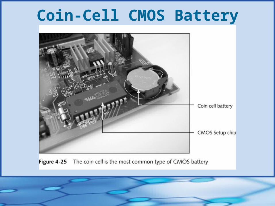
Coin-Cell CMOS Battery
CMOS• Setting startup passwords in CMOS• Categories of CMOS settings
Standard CMOS setup Advanced CMOS setup (aka BIOS Features setup) Advanced Chip Set Setup Power Menu (aka Power Management) IDE HDD Auto-detect Hardware Device Settings (on “jumperless” motherboards
only)
Protecting Documentation and Configuration Settings
• Keep written record of CMOS settings, records of hardware and software installed, and network settings
• Keep well-labeled documentation in a safe place
• Saving and restoring CMOS settings using a third-party utility software
Building a Computer1. Verify that you have all parts you plan to install
2. Prepare computer case
3. Install drives
4. Determine proper configuration settings for motherboard
5. Set jumpers or switches on motherboard
6. Install CPU and CPU cooler
7. Install RAM
8. Install motherboard and attach cabling
continued…
Building a Computer9. Install video card
10.Plug computer into power source; attach monitor and keyboard
11.Boot system and enter CMOS setup
12.Make sure settings are set to the default
13. If booting from a floppy disk, insert a bootable setup disk
14.Observe POST
15.Prepare hard drive for the OS
continued…
Building a Computer16. Reboot the system and run ScanDisk on drive C
17. Connect mouse
18. Install the OS from CD or floppy
19. Change boot order in CMOS
20. Check for conflicts with system resources
21. Install any other expansion cards, and/or drives
22. Verify that all is operating properly; make final OS and/or CMOS adjustments

Installing a Motherboard• Prepare motherboard to go into the case
Set jumpers Add CPU, fan, and heat sink
• Install motherboard in the case
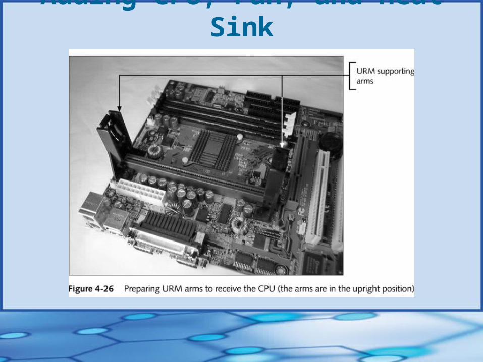
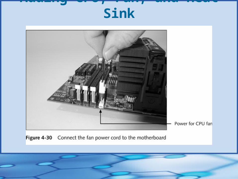
Adding CPU, Fan, and Heat Sink
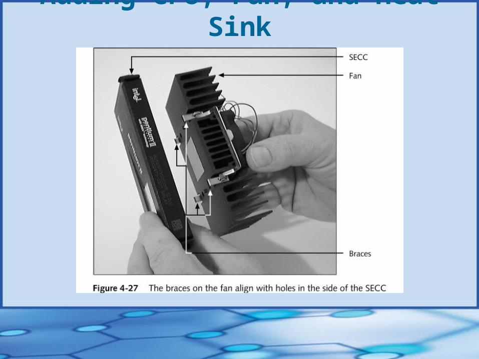
Adding CPU, Fan, and Heat Sink
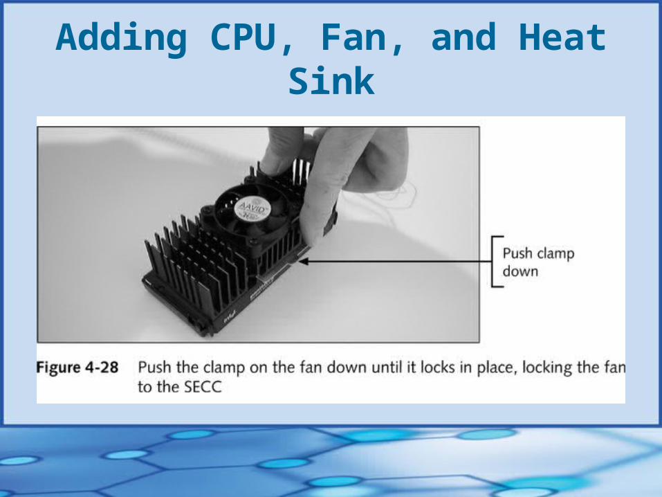
Adding CPU, Fan, and Heat Sink
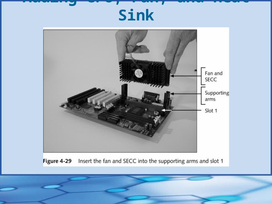
Adding CPU, Fan, and Heat Sink
Adding CPU, Fan, and Heat Sink
Installing the Motherboardin the Case
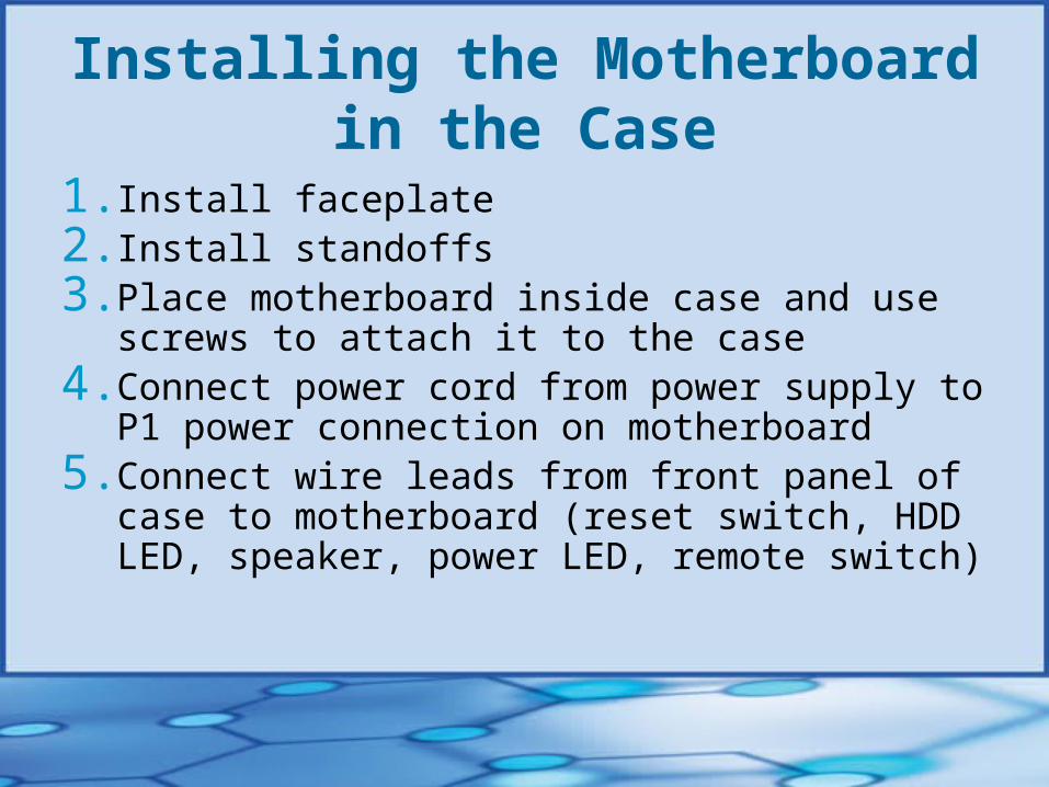
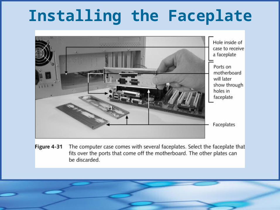
1. Install faceplate2. Install standoffs3. Place motherboard inside case and use screws to
attach it to the case4. Connect power cord from power supply to P1 power
connection on motherboard5. Connect wire leads from front panel of case to
motherboard (reset switch, HDD LED, speaker, power LED, remote switch)
Installing the Faceplate
Installing the Faceplate
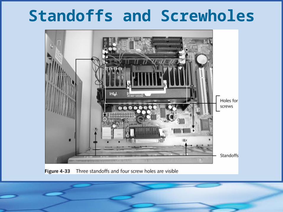
Standoffs and Screwholes
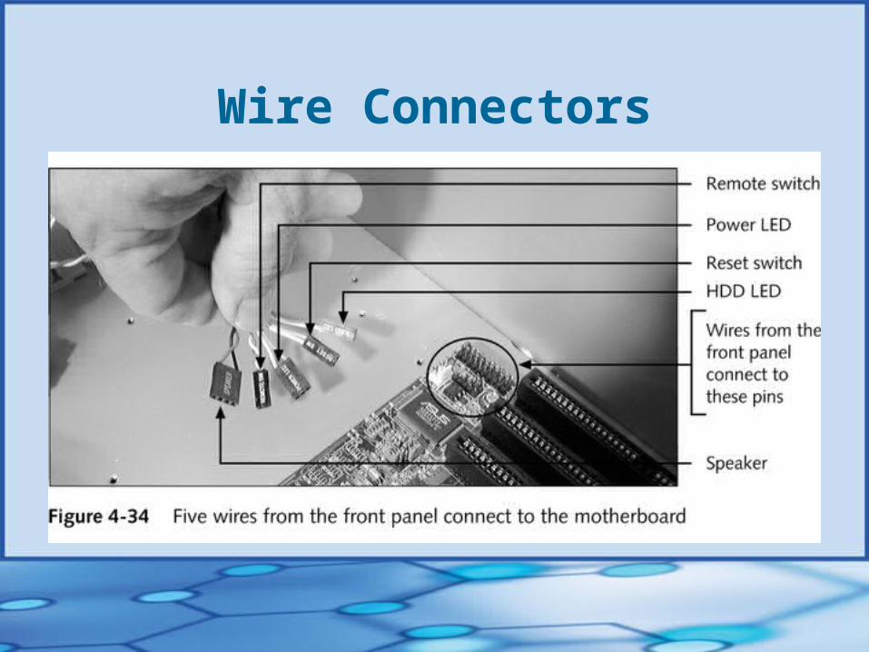
Wire Connectors

Wire Connectors

Completing the Installation• Install drives and other components
• Turn on system and make sure everything is connected properly
• Set configuration data and create rescue desk of settings
Troubleshooting the Motherboard• Look for clues from POST
Reports errors as beep codes
• Cautiously substitute good hardware components for those you suspect are bad
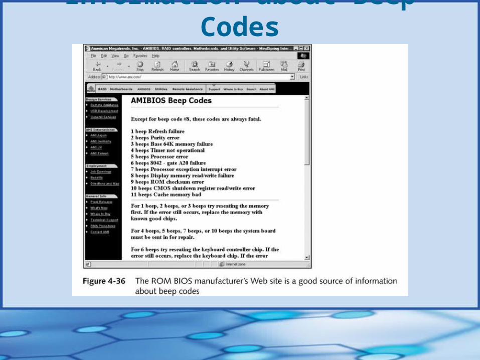
Information about Beep Codes
Chapter Summary• How the components of a computer work in
harmony and with accuracy
• The motherboard Central site of computer logic circuitry Location of most important microchip in the
computer, the CPU