Embed Size (px)
Citation preview
CHAPTER 3
Expected Outcome:
• Able to identify all external forces and their directions, acting on a rigid body
• Able to calculate the moment of a force about a point • Able to analyze and replace a given force acting on a rigid body with an
equivalent system of forces• Draw a free body diagram for a rigid body and solve problems involving
the equilibrium of a rigid body using the three equations of equilibrium or, if possible, using the concept of equilibrium of a 3-Force Body
STATICS OF RIGID BODIES IN TWO DIMENSION
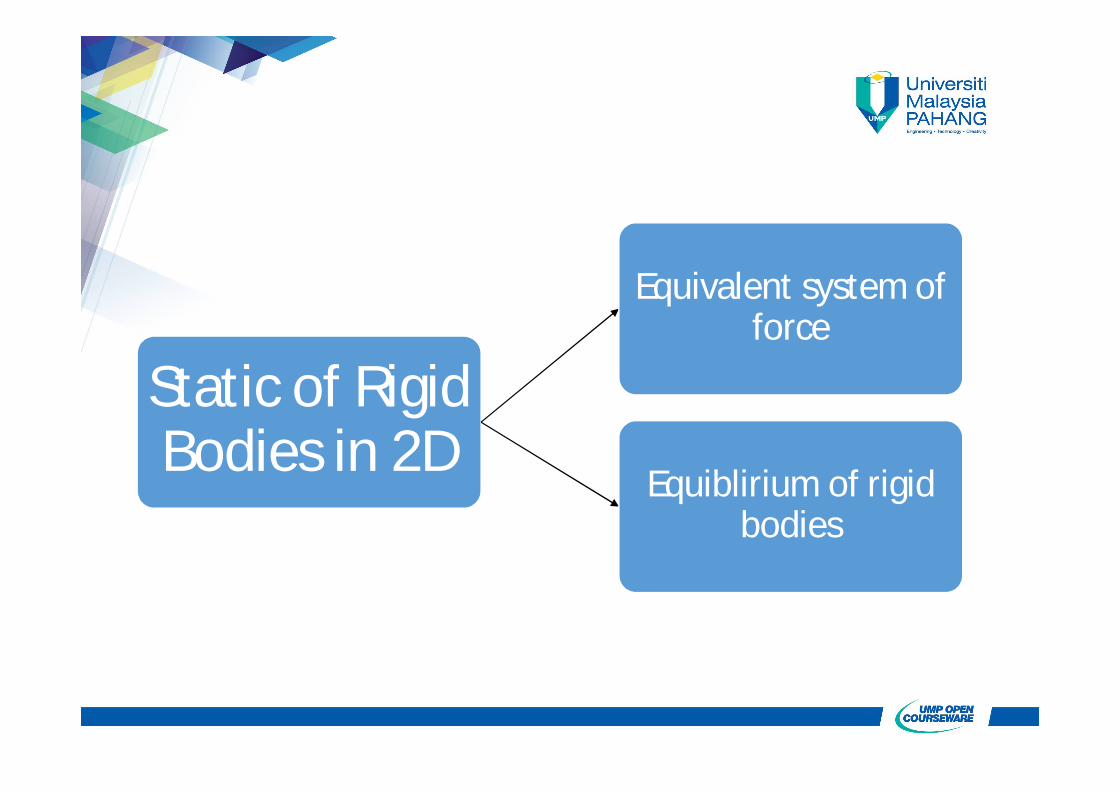
Static of Rigid Bodies in 2D
Equivalent system of force
Equiblirium of rigid bodies
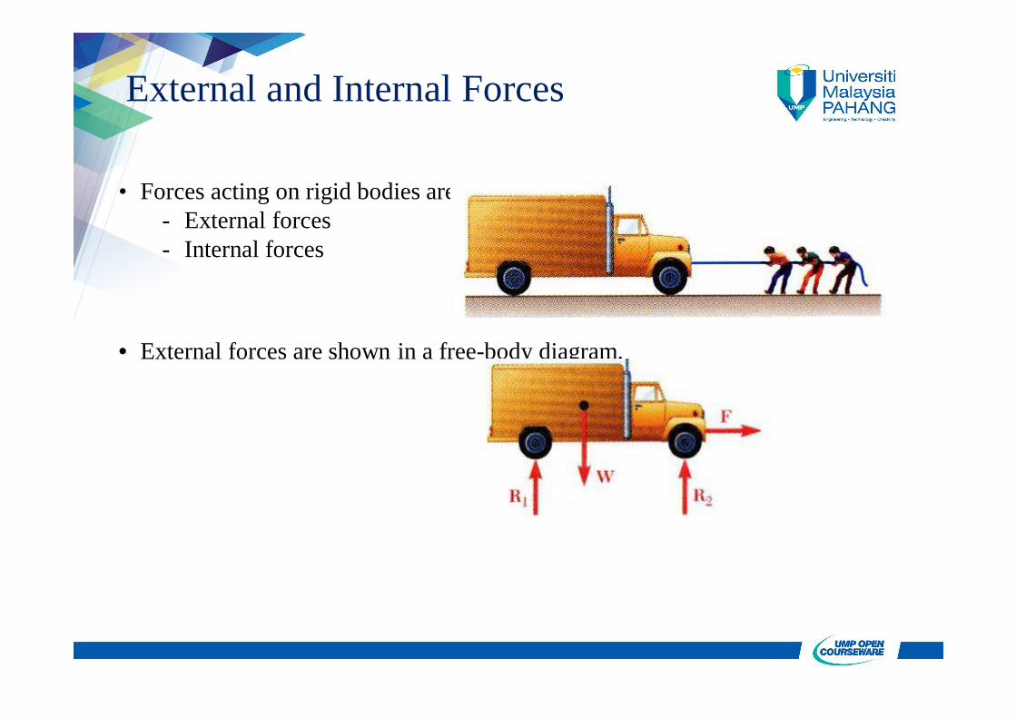
External and Internal Forces
• Forces acting on rigid bodies are divided into two groups:- External forces- Internal forces
• External forces are shown in a free-body diagram.
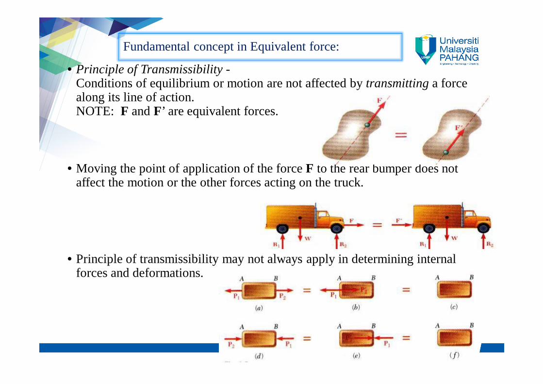
• Principle of Transmissibility -Conditions of equilibrium or motion are not affected by transmitting a force along its line of action.NOTE: F and F’ are equivalent forces.
• Moving the point of application of the force F to the rear bumper does not affect the motion or the other forces acting on the truck.
• Principle of transmissibility may not always apply in determining internal forces and deformations.
Fundamental concept in Equivalent force:
• Concept of Moment
What is moment?


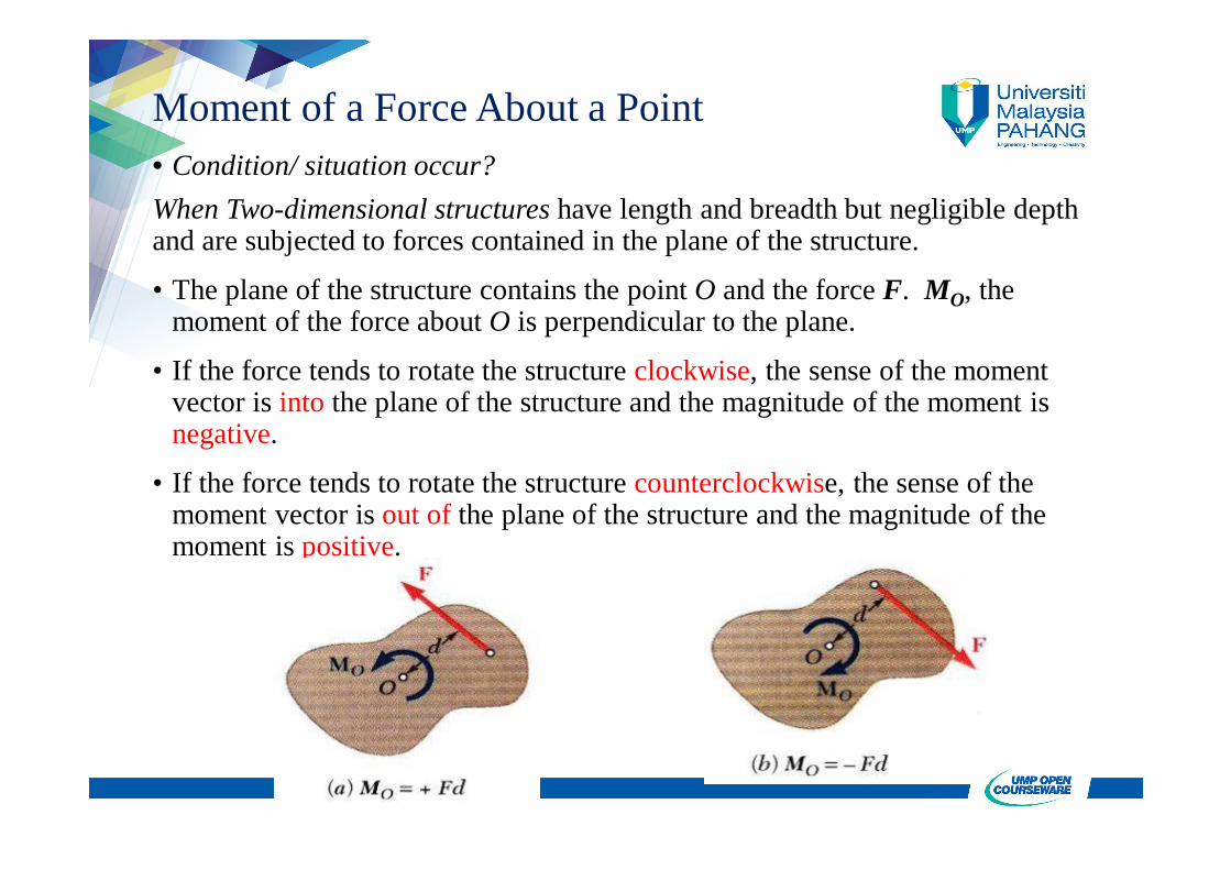
Moment of a Force About a Point• Condition/ situation occur?When Two-dimensional structures have length and breadth but negligible depth and are subjected to forces contained in the plane of the structure.
• The plane of the structure contains the point O and the force F. MO, the moment of the force about O is perpendicular to the plane.
• If the force tends to rotate the structure clockwise, the sense of the moment vector is into the plane of the structure and the magnitude of the moment is negative.
• If the force tends to rotate the structure counterclockwise, the sense of the moment vector is out of the plane of the structure and the magnitude of the moment is positive.
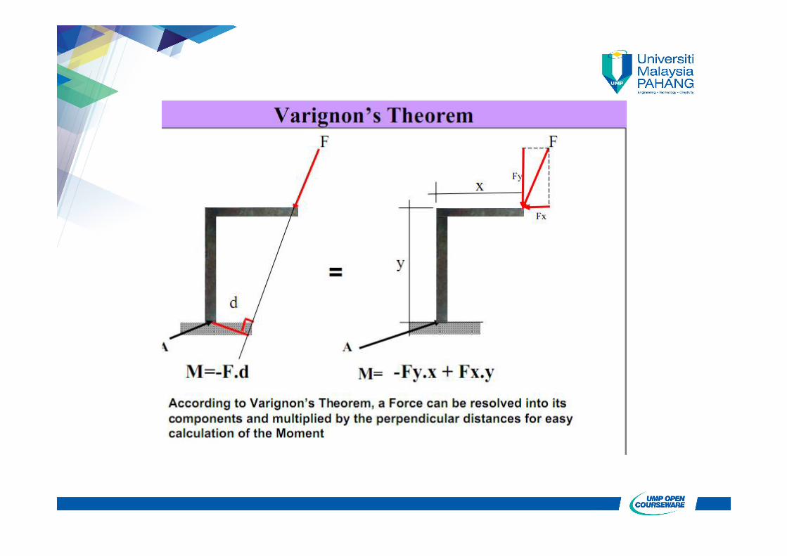
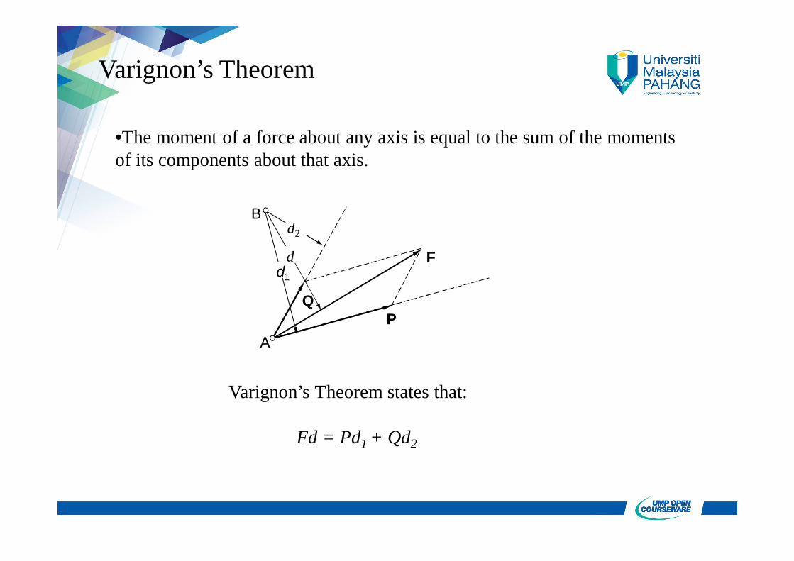
Varignon’s Theorem
B
A
QP
F
d2
dd1
•The moment of a force about any axis is equal to the sum of the moments of its components about that axis.
Varignon’s Theorem states that:
Fd = Pd1 + Qd2
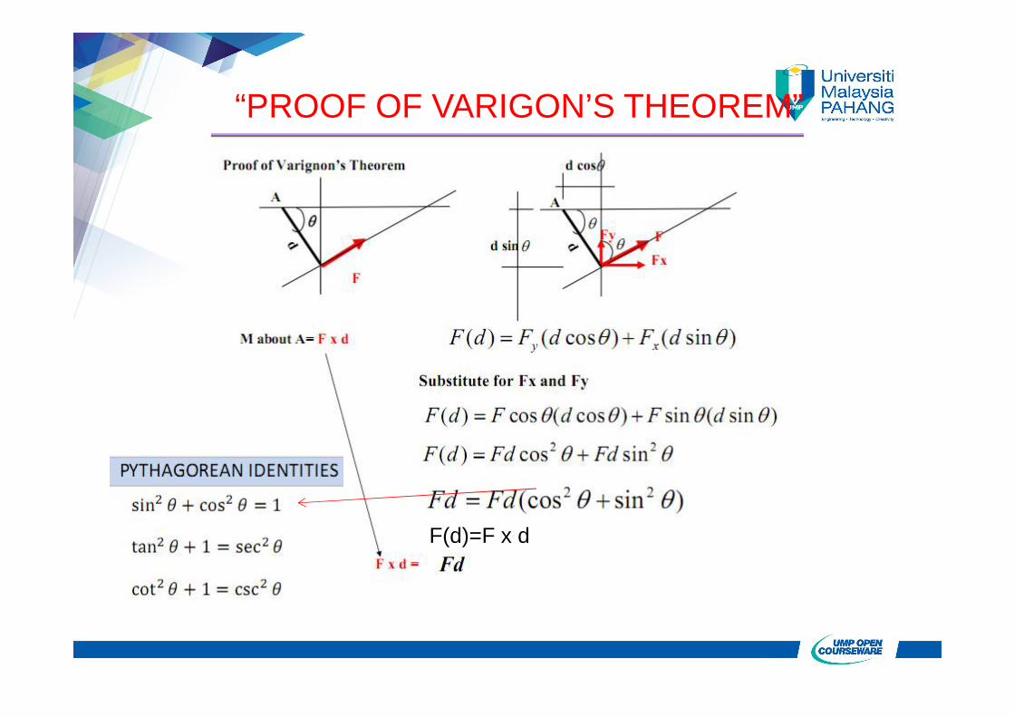
F(d)=F x d
“PROOF OF VARIGON’S THEOREM”
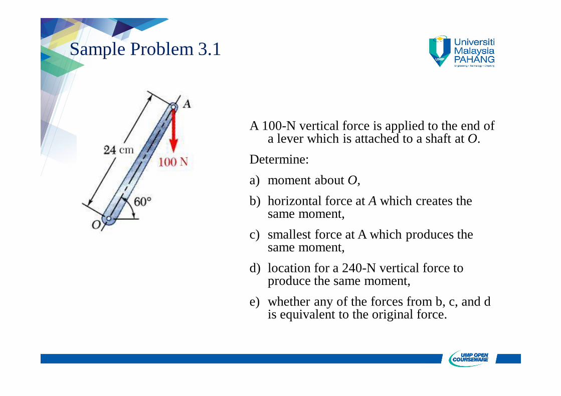
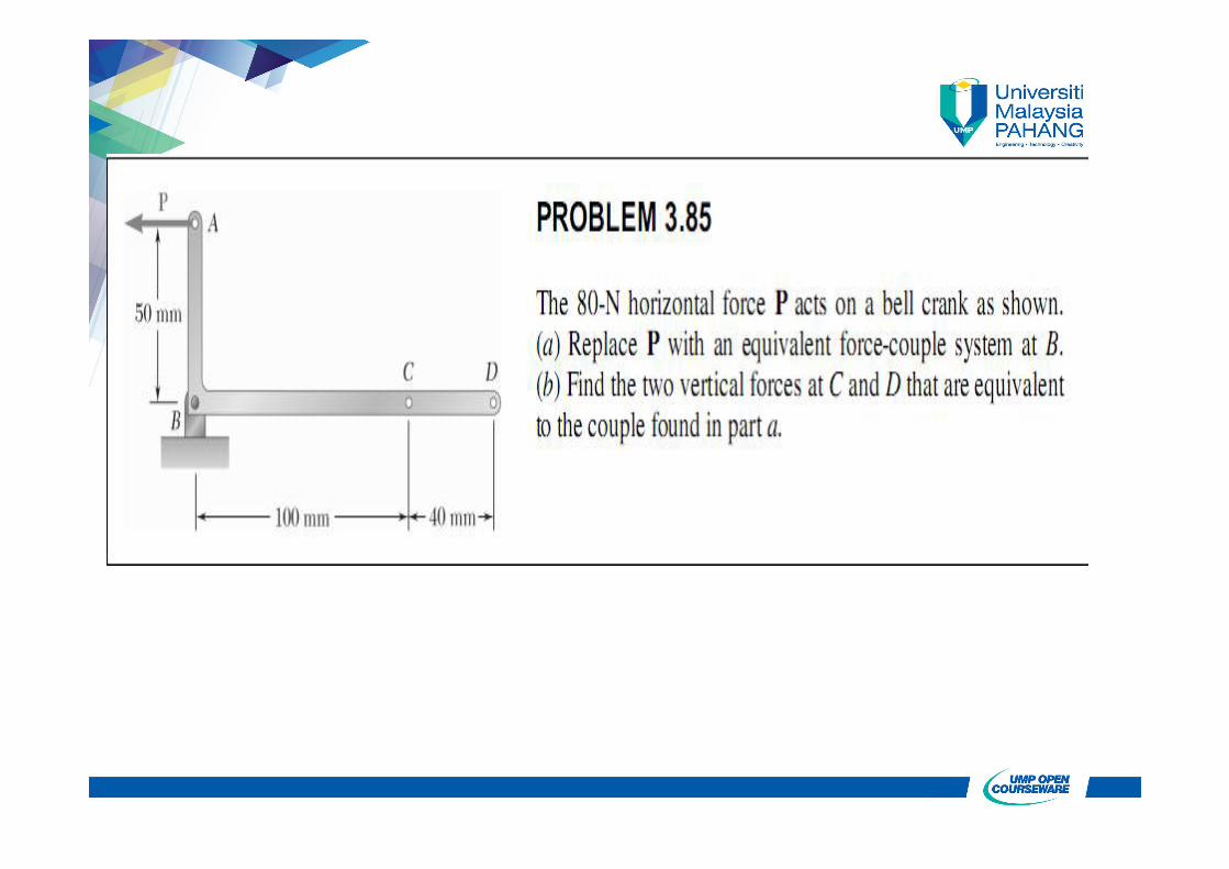
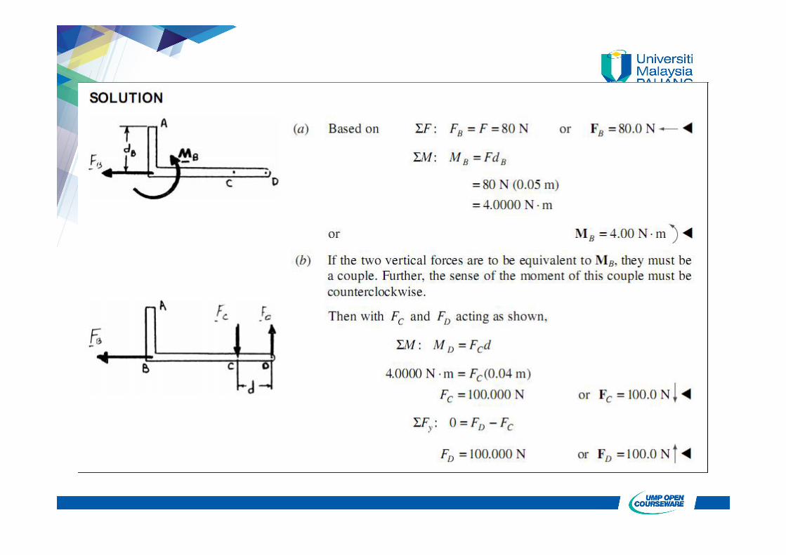
Sample Problem 3.1
A 100-N vertical force is applied to the end of a lever which is attached to a shaft at O.
Determine:a) moment about O,b) horizontal force at A which creates the
same moment,c) smallest force at A which produces the
same moment,d) location for a 240-N vertical force to
produce the same moment,e) whether any of the forces from b, c, and d
is equivalent to the original force.
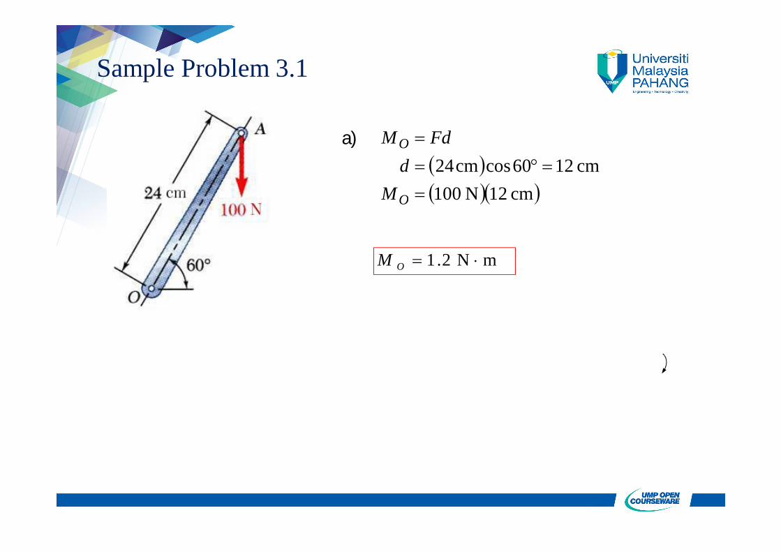
Sample Problem 3.1
a) cm 12N 100
cm 1260coscm24
O
O
Md
FdM
m N 2.1 OM
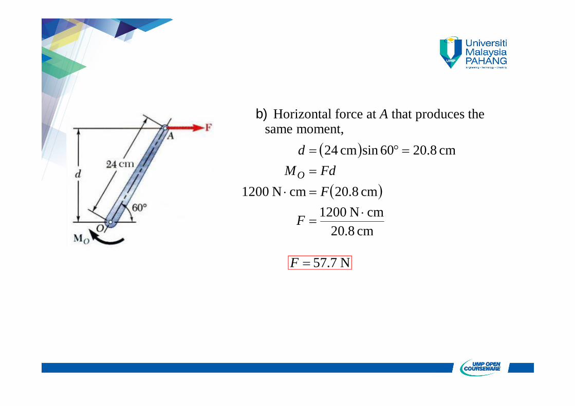
b) Horizontal force at A that produces the same moment,
cm 8.20cm N 1200
cm 8.20cm N 1200
cm 8.2060sincm 24
F
FFdM
d
O
N 7.57F
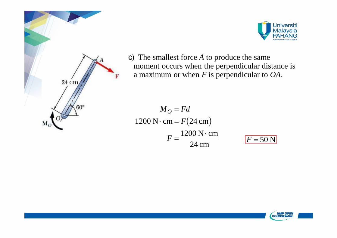
c) The smallest force A to produce the same moment occurs when the perpendicular distance is a maximum or when F is perpendicular to OA.
cm 42cm N 1200
cm 42cm N 1200
F
FFdMO
N 50F

d) To determine the point of application of a 240 N force to produce the same moment,
cm 5cos60
cm 5N 402
cm N 1200N 240cm N 1200
OB
d
dFdMO
cm 10OB
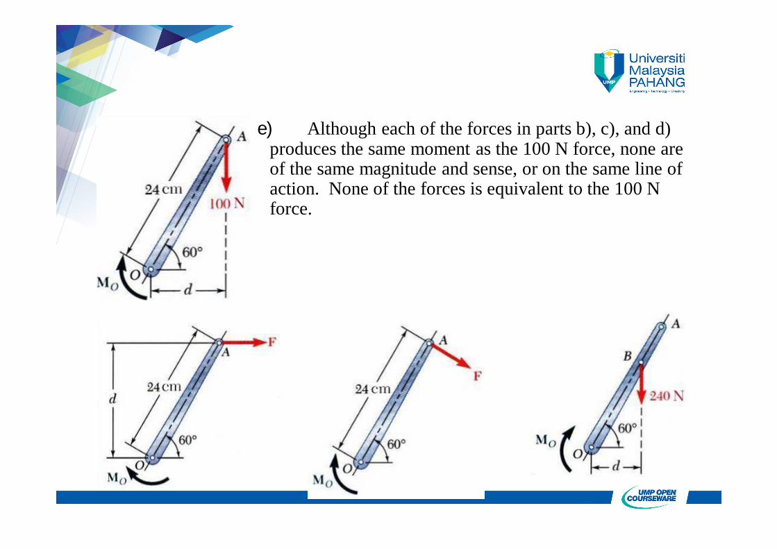
e) Although each of the forces in parts b), c), and d) produces the same moment as the 100 N force, none are of the same magnitude and sense, or on the same line of action. None of the forces is equivalent to the 100 N force.

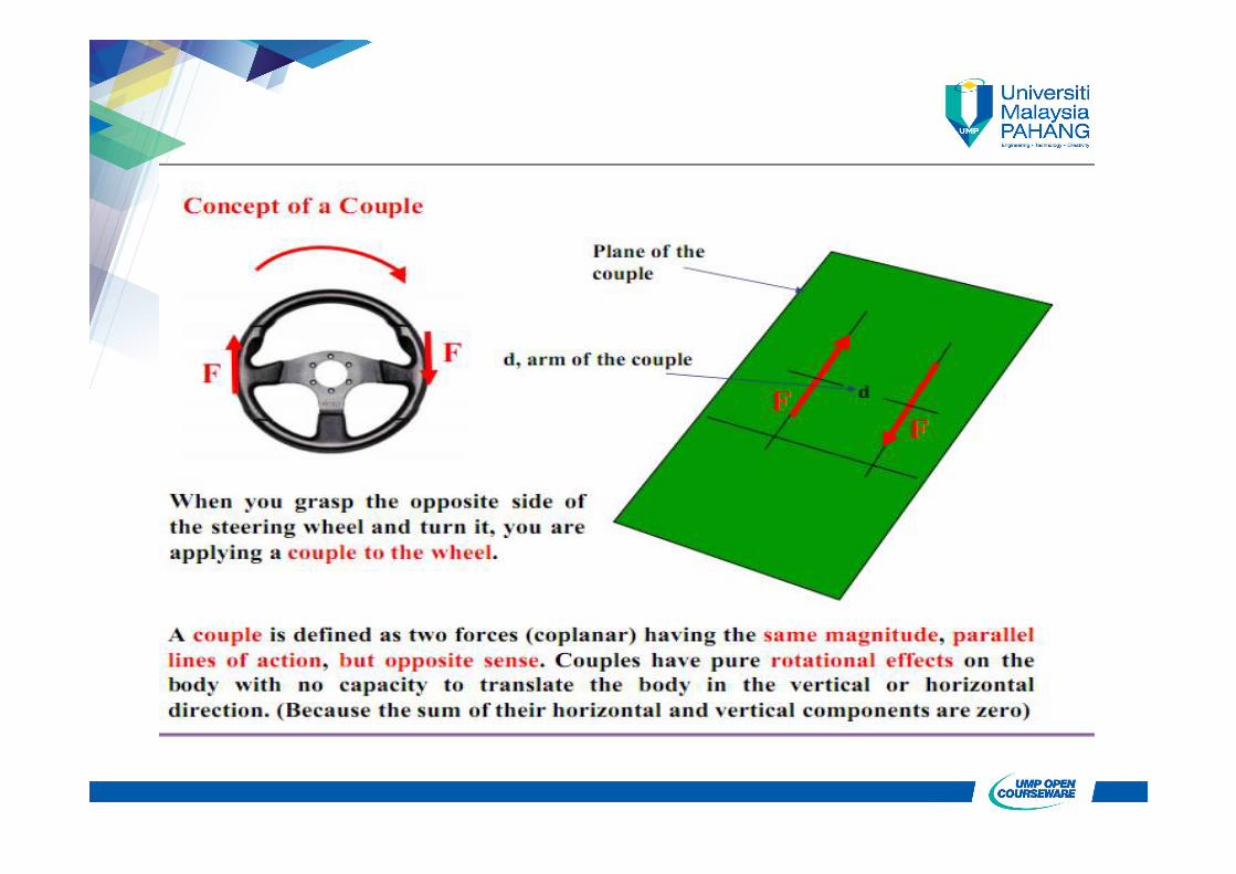
Moment of a Couple
• Two forces F and -F having the same magnitude, parallel lines of action, and opposite sense are said to form a couple.
• Moment of a couple,
FdddF
FdFdMve
)( 21
21
(F = F’)
F’
FA
dd2
d1
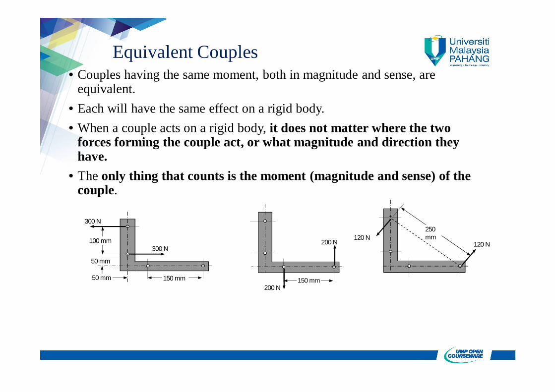
Equivalent Couples• Couples having the same moment, both in magnitude and sense, are
equivalent.• Each will have the same effect on a rigid body.• When a couple acts on a rigid body, it does not matter where the two
forces forming the couple act, or what magnitude and direction they have.
• The only thing that counts is the moment (magnitude and sense) of the couple.
120 N120 N
250 mm
300 N
300 N
50 mm
100 mm
50 mm
150 mm200 N
200 N
150 mm
Addition of Couples
P’
Q’
P
pP’
S
S’
P
p
P’ + S’
P + S
p
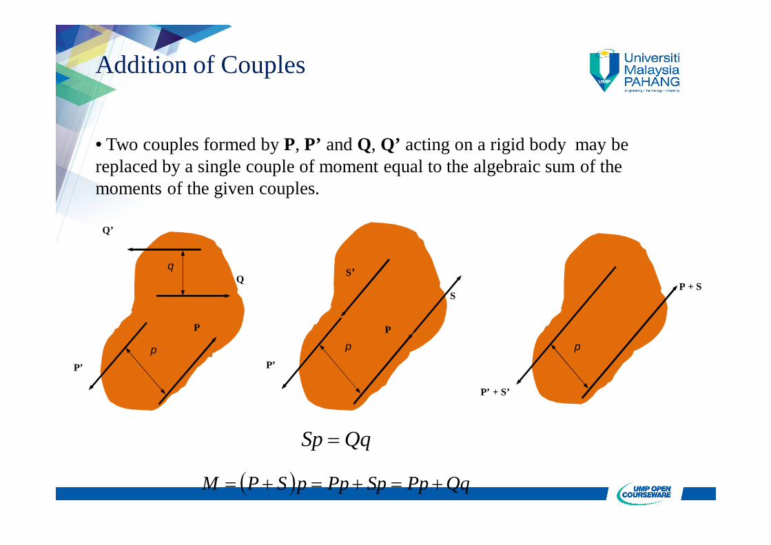
• Two couples formed by P, P’ and Q, Q’ acting on a rigid body may be replaced by a single couple of moment equal to the algebraic sum of the moments of the given couples.
QqSp
QqPpSpPppSPM
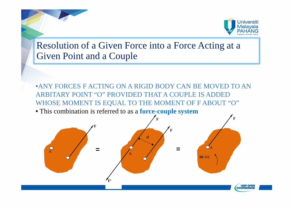
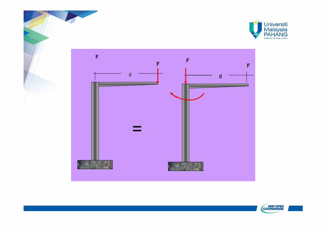
Resolution of a Given Force into a Force Acting at a Given Point and a Couple
•ANY FORCES F ACTING ON A RIGID BODY CAN BE MOVED TO AN ARBITARY POINT “O” PROVIDED THAT A COUPLE IS ADDED WHOSE MOMENT IS EQUAL TO THE MOMENT OF F ABOUT “O”• This combination is referred to as a force-couple system
==
F
A
M=Fd
F
A
F
F’
d
A
F

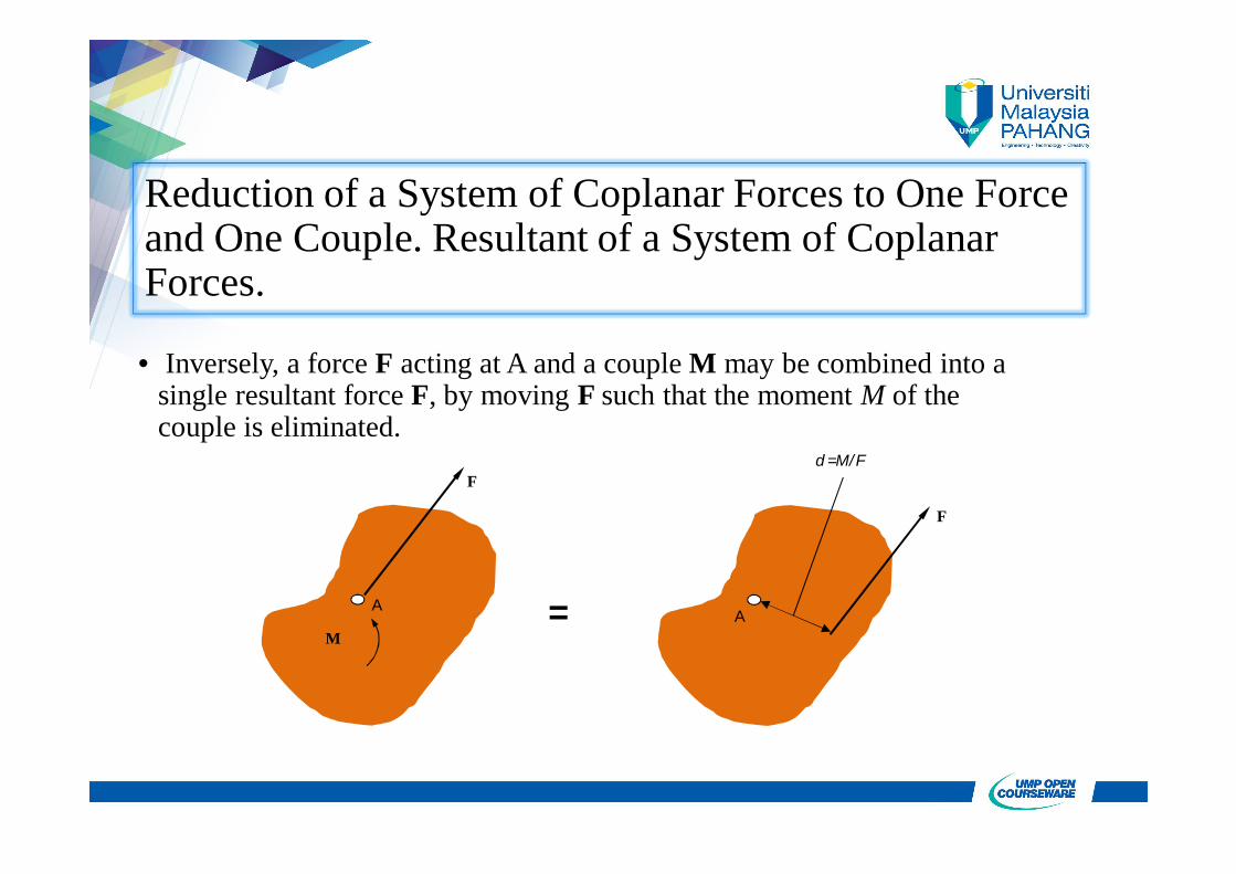
• Inversely, a force F acting at A and a couple M may be combined into a single resultant force F, by moving F such that the moment M of the couple is eliminated.
F
A
d =M/F
=
F
MA
M
Reduction of a System of Coplanar Forces to One Force and One Couple. Resultant of a System of Coplanar Forces.
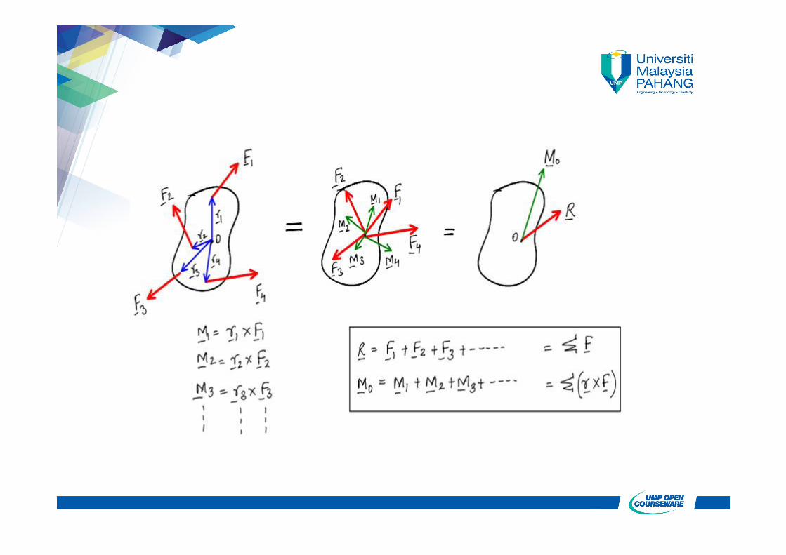
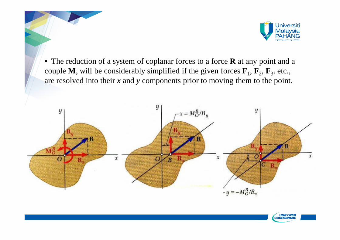
• The reduction of a system of coplanar forces to a force R at any point and a couple M, will be considerably simplified if the given forces F1, F2, F3. etc., are resolved into their x and y components prior to moving them to the point.

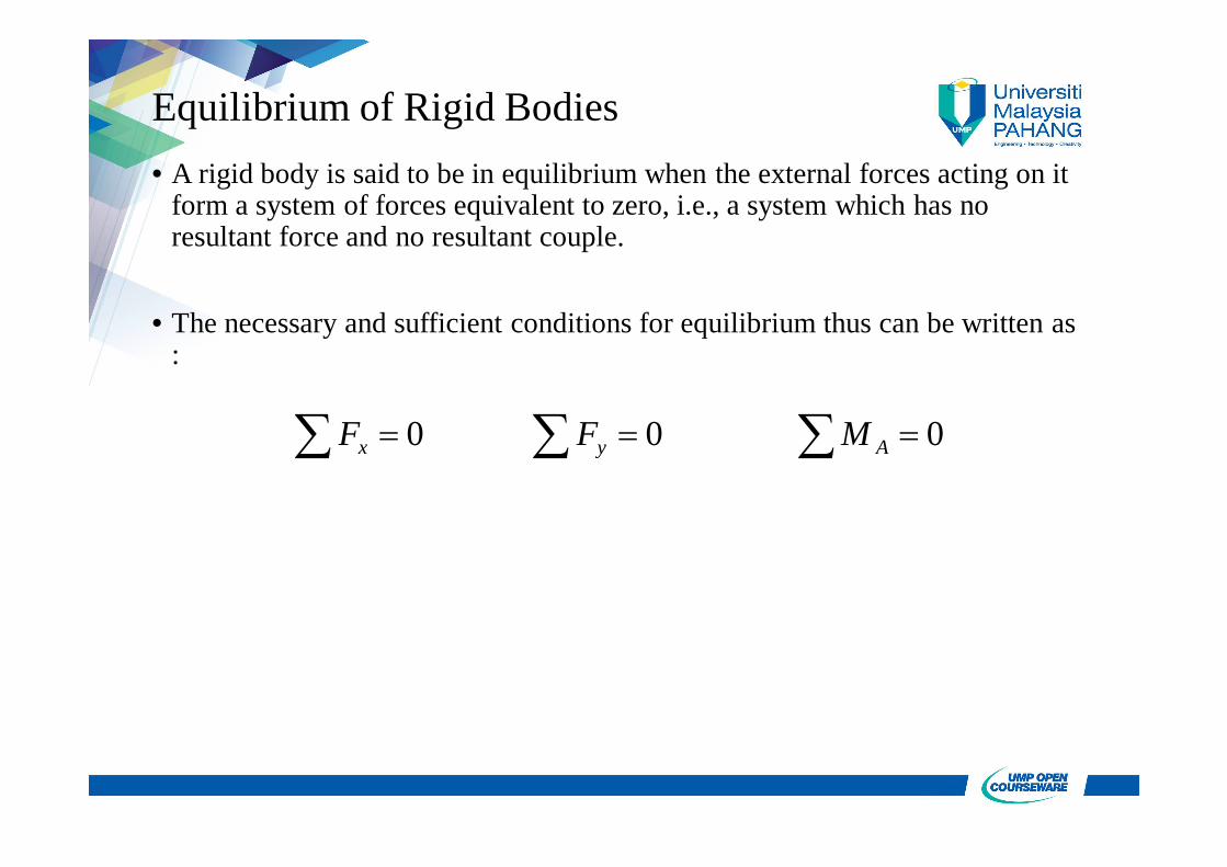
Equilibrium of Rigid Bodies• A rigid body is said to be in equilibrium when the external forces acting on it
form a system of forces equivalent to zero, i.e., a system which has no resultant force and no resultant couple.
• The necessary and sufficient conditions for equilibrium thus can be written as :
000 Ayx MFF
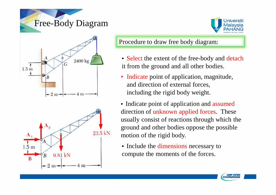
Free-Body Diagram
Procedure to draw free body diagram:
• Select the extent of the free-body and detachit from the ground and all other bodies.• Indicate point of application, magnitude,
and direction of external forces, including the rigid body weight.
• Indicate point of application and assumeddirection of unknown applied forces. These usually consist of reactions through which the ground and other bodies oppose the possible motion of the rigid body.• Include the dimensions necessary to compute the moments of the forces.
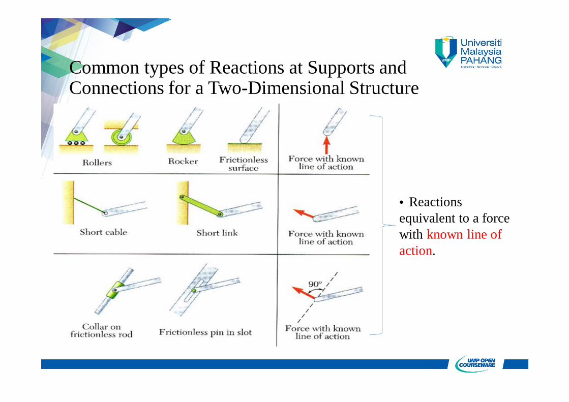
Common types of Reactions at Supports and Connections for a Two-Dimensional Structure
• Reactions equivalent to a force with known line of action.
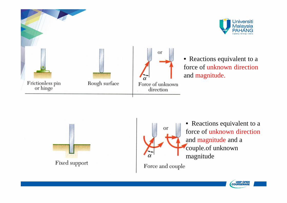
• Reactions equivalent to a force of unknown direction and magnitude.
• Reactions equivalent to a force of unknown direction and magnitude and a couple.of unknown magnitude
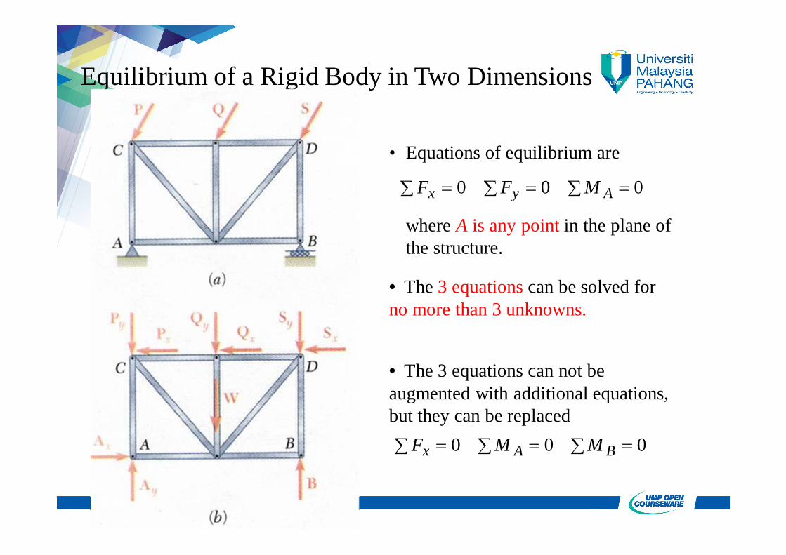
Equilibrium of a Rigid Body in Two Dimensions
• Equations of equilibrium are
000 Ayx MFF
where A is any point in the plane of the structure.
• The 3 equations can be solved for no more than 3 unknowns.
• The 3 equations can not be augmented with additional equations, but they can be replaced 000 BAx MMF
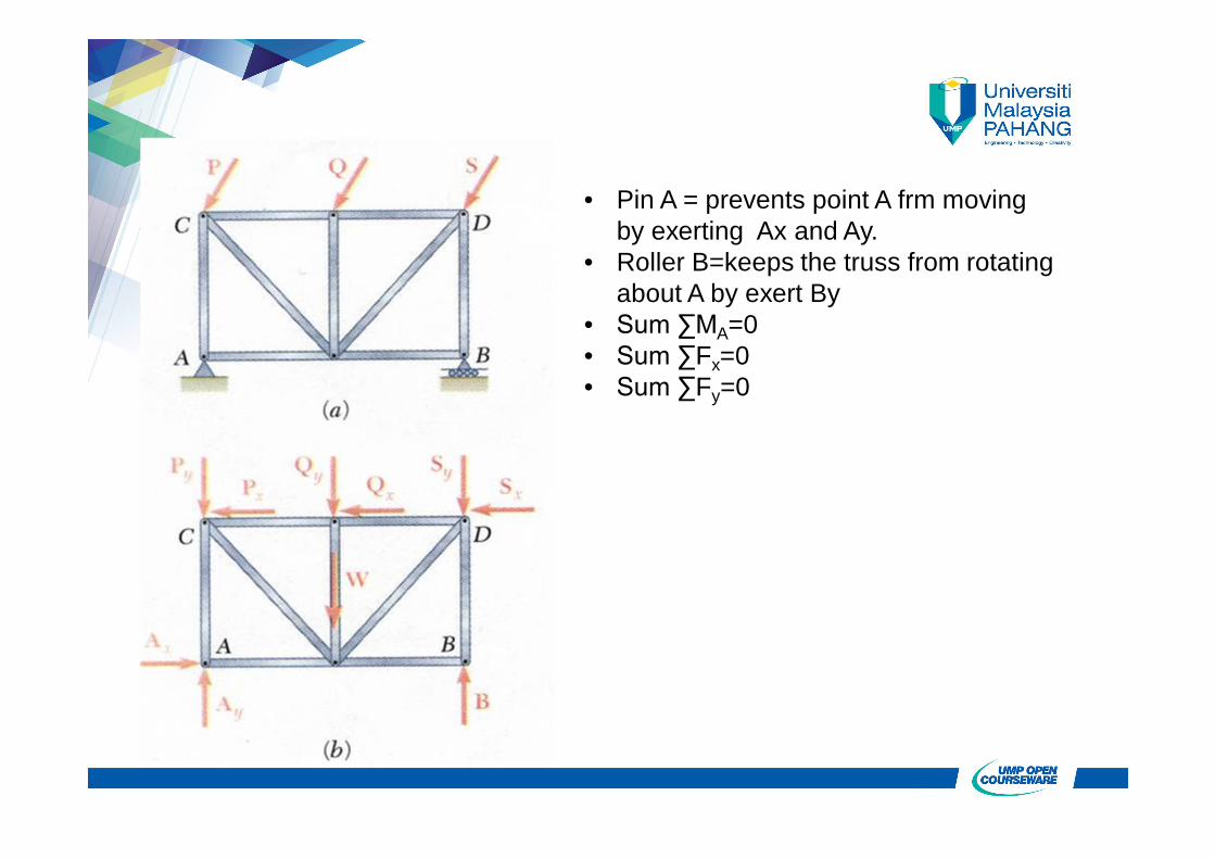
• Pin A = prevents point A frm moving by exerting Ax and Ay.
• Roller B=keeps the truss from rotating about A by exert By
• Sum ∑MA=0• Sum ∑Fx=0• Sum ∑Fy=0
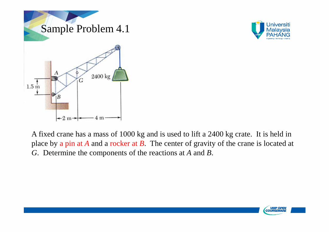
Sample Problem 4.1
A fixed crane has a mass of 1000 kg and is used to lift a 2400 kg crate. It is held in place by a pin at A and a rocker at B. The center of gravity of the crane is located at G. Determine the components of the reactions at A and B.
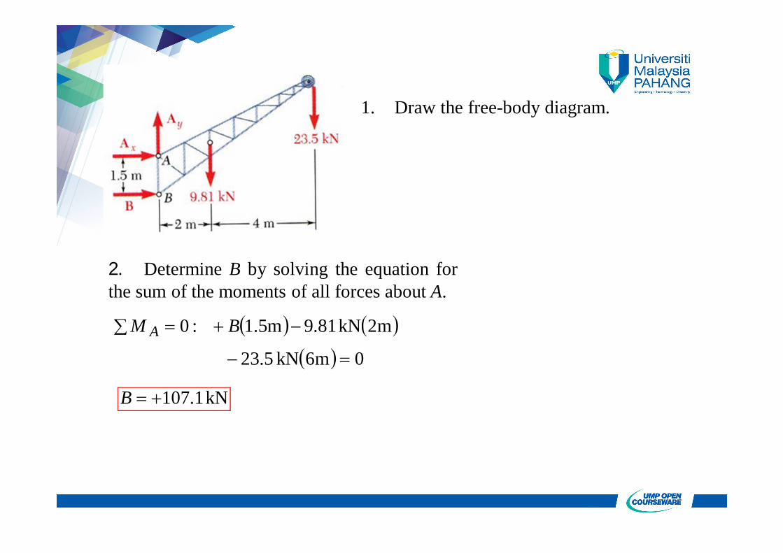
2. Determine B by solving the equation forthe sum of the moments of all forces about A.
1. Draw the free-body diagram.
0m6kN5.23
m2kN81.9m5.1:0
BM A
kN1.107B
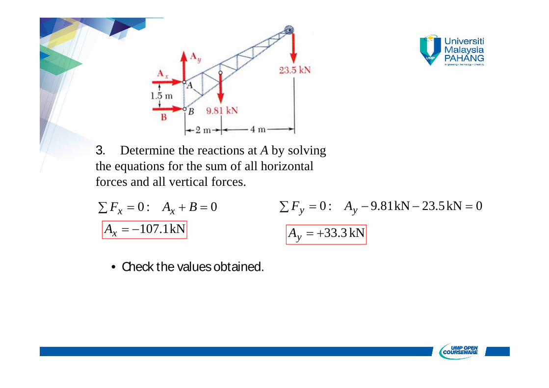
3. Determine the reactions at A by solving the equations for the sum of all horizontal forces and all vertical forces.
0:0 BAF xx
kN1.107xA
0kN5.23kN81.9:0 yy AF
kN 3.33yA
• Check the values obtained.
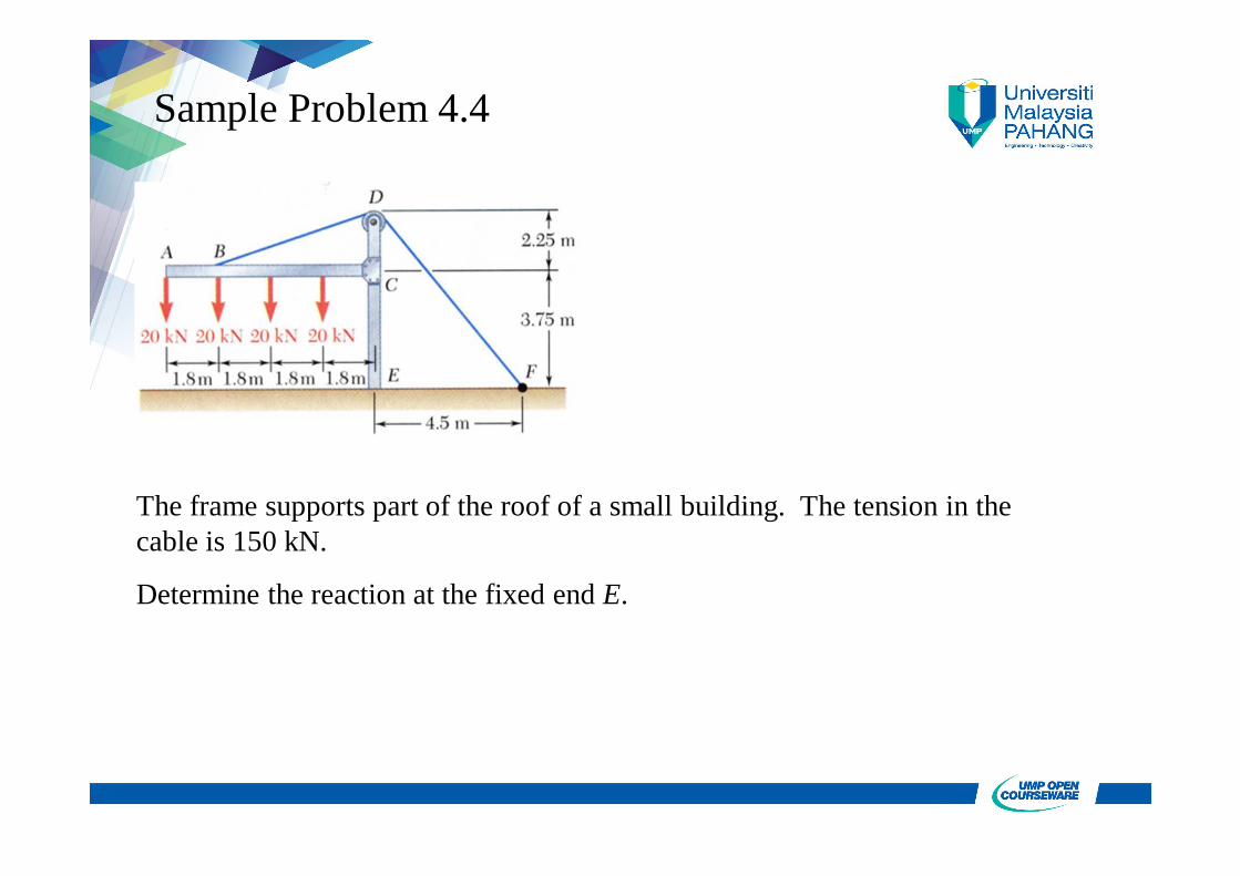
Sample Problem 4.4
The frame supports part of the roof of a small building. The tension in the cable is 150 kN.
Determine the reaction at the fixed end E.
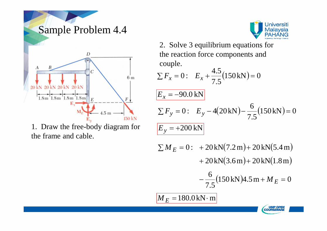
Sample Problem 4.4
1. Draw the free-body diagram for the frame and cable.
2. Solve 3 equilibrium equations for the reaction force components and couple.
0kN1505.75.4:0 xx EF
kN 0.90xE
0kN1505.7
6kN204:0 yy EF
:0EM
0m5.4kN1505.7
6
m8.1kN20m6.3kN20
m4.5kN20m7.2kN20
EM
kN 200yE
mkN0.180 EM
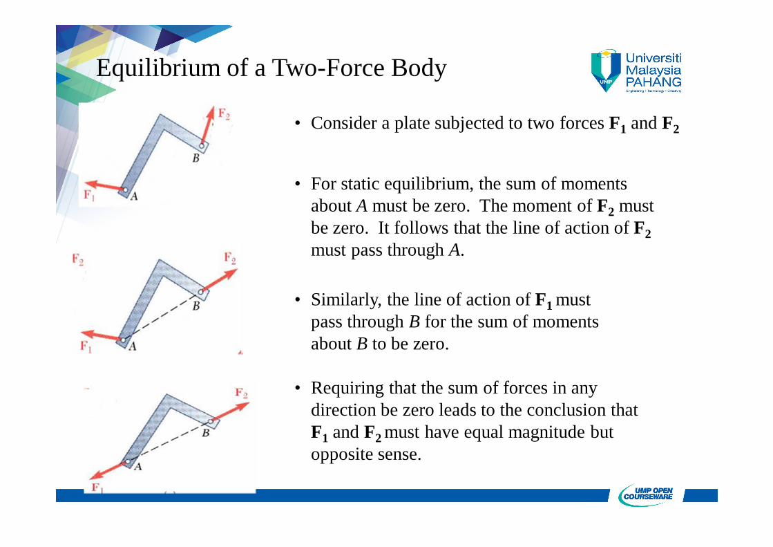
Equilibrium of a Two-Force Body
• Consider a plate subjected to two forces F1 and F2
• For static equilibrium, the sum of moments about A must be zero. The moment of F2 must be zero. It follows that the line of action of F2must pass through A.
• Similarly, the line of action of F1 must pass through B for the sum of moments about B to be zero.
• Requiring that the sum of forces in any direction be zero leads to the conclusion that F1 and F2 must have equal magnitude but opposite sense.

Equilibrium of a Three-Force Body
• Consider a rigid body subjected to forces acting at only 3 points.
• Assuming that their lines of action intersect, the moment of F1 and F2 about the point of intersection represented by D is zero.
• Since the rigid body is in equilibrium, the sum of the moments of F1, F2, and F3 about any axis must be zero. It follows that the moment of F3about D must be zero as well and that the line of action of F3 must pass through D.
• The lines of action of the three forces must be concurrent or parallel.
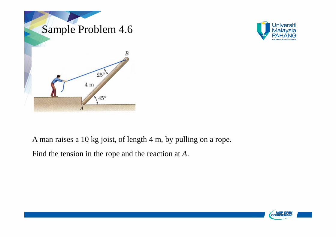
Sample Problem 4.6
A man raises a 10 kg joist, of length 4 m, by pulling on a rope.
Find the tension in the rope and the reaction at A.
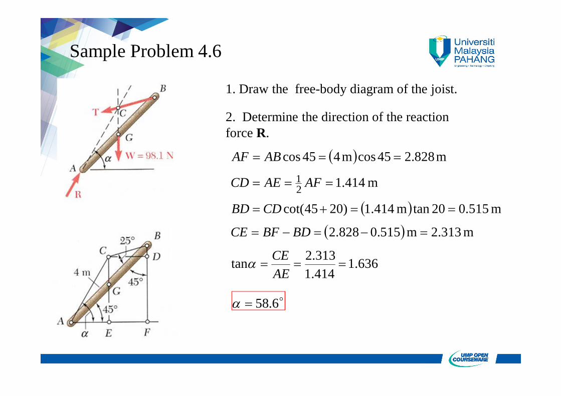
Sample Problem 4.6
1. Draw the free-body diagram of the joist.
2. Determine the direction of the reaction force R.
636.1414.1313.2tan
m 2.313m 515.0828.2
m 515.020tanm 414.1)2045cot(
m 414.1
m828.245cosm445cos
21
AECE
BDBFCE
CDBD
AFAECD
ABAF
6.58
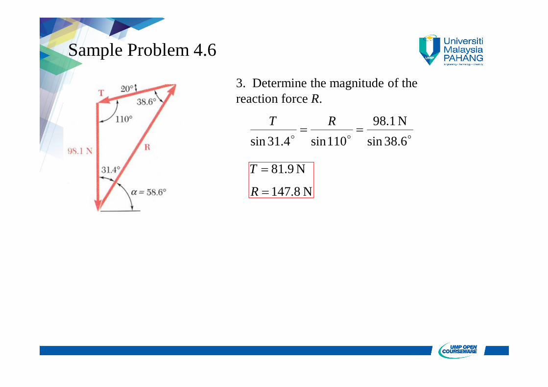
Sample Problem 4.6
3. Determine the magnitude of the reaction force R.
38.6sinN 1.98
110sin4.31sin
RT
N 8.147
N9.81
R
T
References:
1. Beer, Ferdinand P.; Johnston, E. Russell; “Vector Mechanicsfor Engineers - Statics”, 8th Ed., McGraw-Hill, Singapore,2007.


![TheoreticalInvestigationontheElectronicandOpticalPropertie ...downloads.hindawi.com/journals/ijp/2011/570103.pdf · coplanar arrangement. Second [10, 13, 14] ... pulsion forces between](https://img.pdfslide.us/doc/110x75/5ea2654fde6b7750f237d7c6/theoreticalinvestigationontheelectronicandopticalpropertie-coplanar-arrangement.jpg)