Embed Size (px)
Citation preview
AUG 2019 Chapter 37 Electrical System Page 37.i
CHAPTER 37
ELECTRICAL SYSTEM
Section Title Page
37-00 Description . . . . . . . . . . . . . . . . . . . . . . . . . . . . . . . . . . . . . . . . . . . . . . 37.137-10 Battery . . . . . . . . . . . . . . . . . . . . . . . . . . . . . . . . . . . . . . . . . . . . . . . . . 37.237-20 RPM Governor . . . . . . . . . . . . . . . . . . . . . . . . . . . . . . . . . . . . . . . . . . . . 37.337-30 Clutch Actuator . . . . . . . . . . . . . . . . . . . . . . . . . . . . . . . . . . . . . . . . . . . 37.337-40 Lighting System . . . . . . . . . . . . . . . . . . . . . . . . . . . . . . . . . . . . . . . . . . . 37.437-50 External Power Receptacle (Optional) . . . . . . . . . . . . . . . . . . . . . . . . . . . . . 37.437-60 Audio System . . . . . . . . . . . . . . . . . . . . . . . . . . . . . . . . . . . . . . . . . . . . 37.537-70 Warning and Caution Lights . . . . . . . . . . . . . . . . . . . . . . . . . . . . . . . . . . . 37.537-80 Carbon Monoxide Detector . . . . . . . . . . . . . . . . . . . . . . . . . . . . . . . . . . . 37.837-90 Emergency Locator Transmitter (ELT) . . . . . . . . . . . . . . . . . . . . . . . . . . . . 37.837-100 Low Rotor RPM Warning System . . . . . . . . . . . . . . . . . . . . . . . . . . . . . . . 37.937-110 Troubleshooting . . . . . . . . . . . . . . . . . . . . . . . . . . . . . . . . . . . . . . . . . . . 37.1037-120 Electrical Load Analysis . . . . . . . . . . . . . . . . . . . . . . . . . . . . . . . . . . . . . . 37.21

Intentionally Blank
Page 37.ii Chapter 37 Electrical System AUG 2019
CHAPTER 37
ELECTRICAL SYSTEM
37-00 Description
CAUTION
The installation of electrical devices can affect the accuracy and reliability of the electronic tachometer.
A 14-volt DC electrical system which includes an alternator and a sealed lead-acid battery is standard on earlier R44s (Raven Is). A 28-volt DC electrical system is standard on later R44s, R44 IIs, and R44 Cadets. The battery is located either in the engine compartment, under the left (front) seat, or beneath the instrument console (R44s and R44 IIs only).
The circuit breaker panel is on the ledge just forward of the left (front) seat. Breakers are marked to indicate function and amperage and are of the push-to-reset type. Inflight reset of circuit breakers is not recommended.
The battery switch controls the battery relay which disconnects the battery from the electrical system. A wire protected by a fuse near the battery bypasses the battery relay to allow both tachometers and the clock to continue to receive battery power with the battery switch off.
The alternator control unit protects the electrical system from overvoltage conditions. The ammeter indicates current to the battery (“—” indicates discharge). An ALT caution light or ammeter discharge indication in flight indicates low voltage and possible alternator failure. Turn off nonessential electrical equipment and switch alternator off then back on after one second to reset alternator control unit. If ALT light stays on or ammeter still indicates discharge, land as soon as practical.
CAUTION
Continued flight without functioning alternator can result in loss of power to tachometers, producing a hazardous flight condition.
NOTE
Except for emergency procedures, do not operate alternator with battery switched off. The battery helps protect electrical equipment from voltage spikes.
Later aircraft (all R44 Cadets) have an avionics master switch which controls power to the avionics bus. This allows all avionics to be switched on and off by a single switch.
AUG 2019 Chapter 37 Electrical System Page 37.1
37-10 Battery
NOTE
Refer to Concorde Battery Corporation's Owner/Operator's Manual, and Instruction for Continued Airworthiness for battery maintenance procedures.
CAUTION
To minimize risk of electrical discharge: When disconnecting battery, disconnect negative (ground) cable from battery first, then the positive cable. When connecting battery, connect positive cable to battery first, then the negative (ground) cable.
A. Disconnecting and Removing Battery
1. Turn battery switch off.
a. Aft Battery: Remove engine left-hand side cowling. Loosen clamp securing cooling hose to battery cover assembly and disconnect hose. Remove cotter rings and wing nuts to release rods attaching battery cover to lower frames. Remove battery cover.
b. Under-seat battery: Pivot forward left-hand seat forward and remove C748-5 cover assembly. Remove hardware securing D144-6 hold-down assembly to cabin and remove hold-down assembly.
2. Remove hardware securing negative (ground) cable to battery negative terminal.
3. Remove hardware securing positive cable to battery positive terminal. Carefully remove battery.
B. Installing and Connecting Battery
1. Turn battery switch off.
2. Position battery in helicopter and connect positive cable to battery first, then connect the negative (ground) cable. Special torque terminal bolts as noted on battery label and torque stripe per Figure 2-1. Position positive cable’s nipple over terminal.
3. a. Aft Battery: Verify installation and good condition of D832-1 neoprene strips on lower frame.
b. Under-seat battery: Install hardware securing D144-6 hold-down assembly to cabin so it just contacts top of battery (holes are slotted; adjust as required). Standard torque bolt per § 1.320 and torque stripe per Figure 2-1.
4. a. Aft Battery: Position battery cover assembly on battery and install wing nuts and cotter rings to secure rods attaching battery cover to lower frames. Connect cooling hose to battery cover and tighten clamp. Verify security. Install engine left-hand side cowling.
b. Under-seat battery: Install C748-5 cover assembly and pivot forward left-hand seat aft.
Page 37.2 Chapter 37 Electrical System AUG 2019
AUG 2019 Chapter 37 Electrical System Page 37.3
37-20 RPM Governor
The governor maintains engine RPM by sensing changes and applying corrective throttle inputs through a friction clutch which can be easily overridden by the pilot. The governor is only active above 80% engine RPM and can be switched on or off using the toggle switch on the end of the right seat collective.
The governor is designed to assist in controlling RPM under normal conditions. It may not prevent over- or under-speed conditions generated by aggressive flight maneuvers.
CAUTION
When operating at high density altitudes, governor response rate may be too slow to prevent overspeed during gusts, pull-ups, or when lowering collective.
37-30 Clutch Actuator
After the engine is started, it is coupled to the rotor drive system through vee-belts which are tensioned by raising the upper drive sheave. An electric actuator, located between the drive sheaves, raises the upper sheave when the pilot engages the clutch switch. The actuator senses compressive load (belt tension) and switches off when the vee-belts are properly tensioned. The clutch caution light illuminates whenever the actuator circuit is energized, either engaging, disengaging, or re-tensioning the belts. The light stays on until the belts are properly tensioned or completely disengaged.
Belt slack during engine start should be adjusted such that blades begin turning within five seconds of clutch engagement. Excessive slack may cause belts to jump out of sheave grooves during start. Periodic readjustment by a mechanic may be required as belts wear in service.
A fuse located on or near the test switch panel prevents an actuator motor overload from tripping the circuit breaker. If the fuse blows, the actuator motor will stop but the clutch caution light will remain illuminated. An open circuit breaker removes power from both the motor and the light. With an open circuit breaker, no belt tensioning will occur, and the light will not function to indicate an abnormal condition.
CAUTION
Never take off while clutch caution light is on.
37-40 Lighting System
A red anti-collision light is installed on the tailcone and is controlled by the strobe switch. Position lights are installed on each side of the cabin and in the tail and are controlled by the nav lights switch. Post and internal lights (earlier aircraft) or a light at the top of the windshield (later aircraft) illuminate the instruments. Instrument lighting is active when the nav lights switch is on and lighting is dimmed via the knob above the nav lights switch. An overhead map light mounted on a swivel is controlled by an adjacent switch. The map light may be used for emergency lighting of the instrument panel.
Two landing lights are installed in the nose at different vertical angles to increase the lighted area. One landing light switch controls both lights and is located on the cyclic center post.
NOTE
Landing lights operate only when clutch actuator switch is in the engage position.
NOTE
Continuous operation of landing and position lights in flight is recommended to promote collision avoidance.
An optional flashing light may be mounted on the tailcone in addition to the standard anti-collision light. On earlier aircraft, the optional light is controlled by the strobe switch and the standard light is powered whenever the battery switch is on. On later aircraft, the optional light is controlled by a separate switch.
37-50 External Power Receptacle (Optional)
An optional 28-volt MS3506-compatible external power receptacle is located inside the right engine cowl door. When the battery is switched on, the external power relay and the battery relay both close, connecting external power to the aircraft electrical system and battery. The external power relay will not close if reverse polarity is sensed by the receptacle.
A separate wire from the external power receptacle to the battery bypasses the external power and battery relays. This wire allows battery charging via the external receptacle with the battery switch off. A 10-amp circuit breaker at the receptacle opens if current exceeds normal charging levels, and a diode provides polarity protection.
To use ground power for engine starting, have ground personnel connect ground power to the external receptacle prior to engaging starter, disconnect after engine start, and latch cowl door. Starts using ground power assist follow the same procedure as normal starts.
Page 37.4 Chapter 37 Electrical System AUG 2019
37-60 Audio System
A voice-activated intercom/audio system is standard and is controlled by a small control panel above the avionics stack. The ICS volume knob controls intercom volume but does not affect radio volume. The VOX squelch knob is used to set the threshold volume at which the intercom is activated. When the VOX knob is turned fully clockwise, keying is required to activate the intercom.
On R44s and R44 IIs, a toggle switch allows selection of PILOT ISO mode in which the pilot is connected only to the radio while the copilot and rear passengers remain connected to each other via the intercom.
A music input jack is located on the aft seat console on R44s and R44 IIs, or located on a panel between the seat back rests on R44 Cadets. This input is muted when the intercom is active, when transmitting, and during reception of radio signals.
Headset jacks are located in the ceiling. The cyclic grips are equipped with either transmit and intercom buttons or trigger-style intercom/transmit switches. For the trigger-style switch, the first detent activates the intercom and second detent transmits. For R44s and R44 IIs, additional intercom buttons are located inboard of the rear seats and on the left forward floor or seat support. For R44 Cadets, an additional intercom button is located on the outboard side of the left seat.
Audio control panels from several manufacturers are offered as options in place of the standard intercom system. Pilots should consult the manufacturer’s operating instructions if an audio panel is installed.
37-70 Warning and Caution Lights
Warning and caution lights include clutch, main gearbox over-temperature, main and tail gearbox chip, engine fire, starter on, low fuel, fuel filter (R44 IIs), auxiliary fuel pump (R44 IIs), low RPM, alternator, low oil pressure, rotor brake, carbon monoxide, governor off, and full throttle (later aircraft). The clutch light indicates that the clutch actuator is operating. The low RPM light and horn indicate rotor RPM at 97% or below. The engine fire light is actuated by a temperature switch located at the forward end of the horizontal firewall. The low oil pressure and low fuel lights are actuated by sensors in those systems and are independent of the gage indicators. The alternator light warns of a possible alternator failure. The auxiliary fuel pump light monitors fuel pressure from the auxiliary pump and illuminates due to pump failure or when the clutch switch is not engaged. The fuel filter light warns of possible filter contamination. The governor-off light indicates the RPM governor is switched off.
The main and tail gearbox chip detectors are magnetic devices located in the drain plug of each gearbox. When metallic particles are drawn to the magnets they close an electrical circuit, illuminating the caution light. Metal particles may be caused by a failing bearing or gear, thus giving warning of impending gearbox failure. The main gearbox over-temp light is actuated by a temperature switch located near the input pinion.
AUG 2019 Chapter 37 Electrical System Page 37.5
Page 37.6 Chapter 37 Electrical System AUG 2019
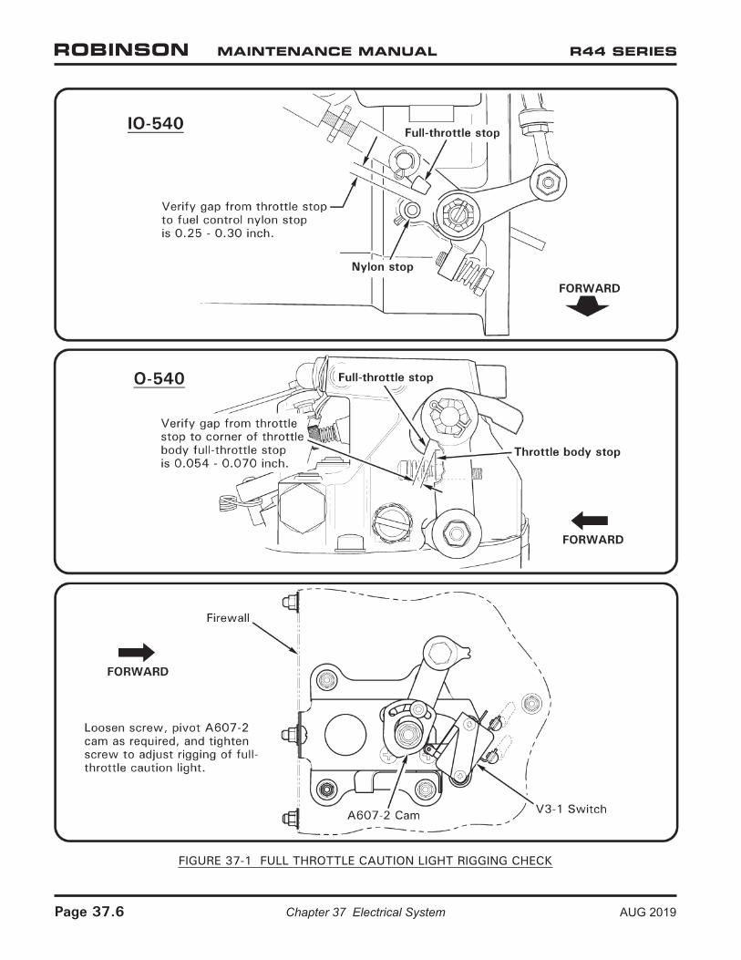
FIGURE 37-1 FULL THROTTLE CAUTION LIGHT RIGGING CHECK
37-70 Warning and Caution Lights (continued)
The carbon monoxide light is actuated by a sensor above the pilot’s heater outlet and indicates elevated cabin carbon monoxide levels.
The full throttle light is activated by a switch in the throttle linkage and indicates that the engine is near full throttle.
A. Full Throttle Caution Light
a. Rigging Check
i. Turn fuel shut-off valve off.
ii. Turn battery switch on. Raise collective full up and slowly rotate twist grip open until full throttle caution light just illuminates.
iii. A. IO-540: Refer to Figure 37-1. Verify gap from throttle stop to fuel control nylon stop is 0.25–0.30 inch. Adjust as required per step 2b.
B. O-540: Refer to Figure 37-1. Verify gap from throttle stop to corner of throttle body full-throttle stop is 0.054–0.070 inch. Adjust as required per step 2b.
iv. Lower collective & turn battery switch off. Turn fuel shut-off valve on.
b. Switch Adjustment
i. A. IO-540: Refer to Figure 37-1. Raise collective full up, rotate (throttle) twist grip as required, loosen screw, and pivot A607-2 slotted cam (in throttle linkage, forward of vertical firewall) so V3-1 switch activates when throttle stop is approximately 0.027 inch from fuel control nylon stop. Tighten screw.
B. O-540: Refer to Figure 37-1. Raise collective full up, rotate (throttle) twist grip as required, loosen screw, and pivot A607-2 slotted cam (in throttle linkage, forward of vertical firewall) so V3-1 switch activates when throttle stop is approximately 0.062 inch from corner of throttle body full-throttle stop. Tighten screw.
ii. Perform rigging check per step 2a.
AUG 2019 Chapter 37 Electrical System Page 37.7
37-80 Carbon Monoxide Detector
The carbon monoxide (CO) detector, if installed, indicates elevated cabin CO levels. CO is an odorless, toxic gas present in engine exhaust which causes headaches, drowsiness, and possible loss of consciousness. CO levels may become elevated due to an exhaust leak or exhaust recirculation during prolonged hovering.
The CO detector system consists of a sensor above the pilot’s heater outlet and a caution light. A system check (light flashes twice) is performed each time power is switched on. A sensor malfunction is indicated by a continuing flash every four seconds.
If the caution light illuminates, shut off heater and open nose and door vents as required to ventilate the cabin. If hovering, land or transition to forward flight. If symptoms of CO poisoning (headache, drowsiness, dizziness) accompany caution light, land immediately. Have exhaust system inspected before next flight.
Many chemicals can damage the CO sensor. Avoid use of solvents, detergents, or aerosol sprays near the sensor. Temporarily tape off openings in top and bottom of sensor housing when cleaning cabin interior.
37-90 Emergency Locator Transmitter (ELT)
The Emergency Locator Transmitter (ELT) installation consists of a transmitter with internal battery pack, an external antenna, and a remote switch/annunciator. The transmitter is mounted to the upper steel tube frame and is accessible through the aft, upper cowl door. The remote switch/annunciator is located left of the cyclic stick.
The ELT is operated by a switch on the transmitter and a remote switch in the cockpit. The transmitter switch has been secured in the AUTO or ARM position at installation and should always be in this position for flight. The remote switch/annunciator is a three position switch with indicator light. This switch should also be in the AUTO or ARMED (middle) position for flight. With both switches set to AUTO/ARM, the ELT will begin transmitting when subjected to a high “G” load. When the unit is transmitting, the red indicator light illuminates.
Moving the remote switch to ON activates the transmitter. Use the ON position if an emergency landing is imminent and time permits.
If the ELT is inadvertently activated, use the RESET position of the remote switch to stop transmission and reset the unit. The red indicator will extinguish when unit is reset.
NOTE
Earlier aircraft may have ELT installations without remote switch.
For more detailed instructions on ELT operation, maintenance, and required tests, refer to manufacturer’s instructions supplied with the unit.
Page 37.8 Chapter 37 Electrical System AUG 2019
37-100 Low Rotor RPM Warning System
When the collective is raised 0.2 to 0.4 inches (measured at grip) above fully down, the low-rotor RPM warning unit must activate the low-rpm warning horn and low-rpm light at 97% to 96% rotor RPM; horn and light must turn off above 96% to 97% rotor RPM.
The low rotor RPM warning unit is located on the inside of the upper console, mounted on the left vertical panel. Adjustments are made by turning an exposed screw on warning unit, accessible by removing a black-plastic plug from a 3/8-inch diameter hole on the left vertical panel. The A569 warning unit’s adjustment screw sensitivity is approximately 2 turns per 1% change. If warning unit cannot be adjusted to range stated above, it must be replaced.
AUG 2019 Chapter 37 Electrical System Page 37.9

Intentionally Blank
Page 37.10 Chapter 37 Electrical System AUG 2019
AUG 2019 Chapter 37 Electrical System Page 37.11
37-110 Troubleshooting
Following are some troubles and corrections. When investigating trouble, eliminate causes one by one, beginning with the most probable.
A. A569 Low Rotor RPM Warning Unit
Perform following tests prior to replacing A569 low rotor-rpm warning unit:
1. Verify:
a. Low RPM light bulb is functional.b. Battery switch off.c. Full-down collective.d. Horn circuit breaker in.
2. Access and disconnect both horn and A569 low rotor-rpm warning unit from airframe electrical wiring.
3. Turn battery switch on and verify Horn Start circuit breaker remains in. If Horn Start circuit breaker pops then -70 wire is shorted to ground; repair as required. Turn battery switch off.
4. On the warning unit’s airframe electrical connector, install a jumper between wires -70 & -75.
5. Turn battery switch on and verify Horn Start circuit breaker remains in. If Horn Start circuit breaker pops then a short-to-ground exists in -75 wire and/or collective-activated V3-1 switch; repair as required.
6. Fully raise collective and verify Horn Start circuit breaker remains in and Low RPM light illuminates. If Horn Start circuit breaker pops then a short-to-ground exists in -76 wire and/or -78 wire and/or collective-activated V3-1 switch; repair as required. If Low RPM light does not illuminate then collective-activated V3-1 switch is faulty or misadjusted and/or an open exists in -70, -75, or -76 wires.
7. Slowly raise and lower collective fully several times while simultaneously manipulating throttle. Verify Horn Start circuit breaker remains in and Low RPM light remains illuminated whenever collective is raised. If Horn Start circuit breaker pops then a short-to-ground condition is occurring in -70, -75, or -76 wires and/or collective-activated V3-1 switch due to collective movement. Check for pinched/rubbing wiring and repair as required.
8. Turn battery switch off. Connect horn to airframe wiring.
9. Turn battery switch on. Raise collective and verify horn activates and has consistent tone. If Horn Start circuit breaker pops then horn is faulty and/or -78 wire is shorted to ground; repair as required. If horn fails to activate then -79 wire is open or horn is faulty; repair as required. If tone is inconsistent then horn is faulty and/or poor connections exist; repair as required.
Page 37.12 Chapter 37 Electrical System AUG 2019
37-110 Troubleshooting (continued)
A. A569 Low Rotor RPM Warning Unit (continued)
10. Check A999 master radio relay current draw:
a. Battery switch off and belt tension actuator fully disengaged.
b. Disconnect A569 low-rpm warning unit’s connector and place an ammeter in series (positive lead on pin 10) between pins 10 and 11 on airframe side of connector.
c. Battery switch on, Horn Start and Clutch Start circuit breakers in, avionics off, rotor brake released, mixture at idle cut-off.
d. Select key switch to Start (Both on Raven Ils) position and crank engine. Note and record current draw at ammeter while cranking engine. Select key switch to Off position.
e. Disconnect 582 wire at tab on starter solenoid and isolate connector (do not let it ground). Select key switch to Start position. Note and record current draw at ammeter; for 14-volt systems current should be 94–156 milliamps and a buzzing sound should be heard from the starter vibrator (for 28-volt systems current should be 40–70 milliamps and starter vibrator should make no noise). Select key switch to Off position.
11. Check starter circuit:
a. Battery switch off and belt tension actuator fully disengaged.
b. Disconnect A569 low-rpm warning unit’s connector and jump pins 10 and 11 on airframe side of connector.
c. Battery switch on, Horn Start and Clutch Start circuit breakers in, rotor brake released, mixture at idle cut-off.
d. Select key switch to Start position and crank engine. If engine does not crank there is a problem in the starter circuit. If engine cranks then there is a problem in either the A569 unit or the sense circuit.
12. Check A569 sense circuit:
a. Battery switch on.
b. Momentarily engage clutch and verify Clutch light illuminates then disengage clutch completely (switch to remain disengaged throughout this sequence).
c. Battery switch off.
d. Disconnect D602 time delay connector. Ground airframe-side plug’s pin 1 thru a suitable voltage (post-light type) lamp.
CAUTION
Failure to ground pin 1 thru a suitable voltage lamp (such as direct grounding) may result in wiring damage.
AUG 2019 Chapter 37 Electrical System Page 37.13
37-110 Troubleshooting (continued)
A. A569 Low Rotor RPM Warning Unit (continued)
12. e. Verify less than 200 ohms (20 ohm nominal for 14-volt system; 70 ohm nominal for 28-volt system) to ground at pin 4 and at pin 5 on ship side of A569 connector.
f. Battery switch on.
g. With A569-5 unit connected to airframe harness, verify voltage does not exceed 0. 5V from pin 4 to ground and from pin 5 to ground.
h. Battery switch on, Horn Start and Clutch Start circuit breakers 1n, rotor brake released, mixture at idle cut-off.
i. Select key switch to Start position and crank engine. Failure of engine to crank indicates problem in A569 unit.
13. Upon completion of preceding tests, a faulty A569 low rotor-rpm warning unit may be replaced and adjusted per § 37-100.
Page 37.14 Chapter 37 Electrical System AUG 2019
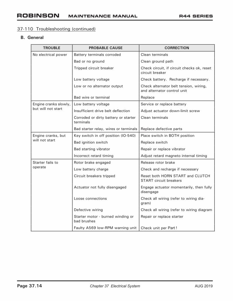
37-110 Troubleshooting (continued)
B. General
TROUBLE PROBABLE CAUSE CORRECTION
No electrical power Battery terminals corroded Clean terminals
Bad or no ground Clean ground path
Tripped circuit breaker Check circuit, if circuit checks ok, reset circuit breaker
Low battery voltage Check battery. Recharge if necessary.
Low or no alternator output Check alternator belt tension, wiring, and alternator control unit
Bad wire or terminal Replace
Engine cranks slowly, but will not start
Low battery voltage Service or replace battery
Insufficient drive belt deflection Adjust actuator down-limit screw
Corroded or dirty battery or starter terminals
Clean terminals
Bad starter relay, wires or terminals Replace defective parts
Engine cranks, but will not start
Key switch in off position (IO-540) Place switch in BOTH position
Bad ignition switch Replace switch
Bad starting vibrator Repair or replace vibrator
Incorrect retard timing Adjust retard magneto internal timing
Starter fails to operate
Rotor brake engaged Release rotor brake
Low battery charge Check and recharge if necessary
Circuit breakers tripped Reset both HORN START and CLUTCH START circuit breakers
Actuator not fully disengaged Engage actuator momentarily, then fully disengage
Loose connections Check all wiring (refer to wiring dia-gram)
Defective wiring Check all wiring (refer to wiring diagram
Starter motor - burned winding or bad brushes
Repair or replace starter
Faulty A569 low-RPM warning unit Check unit per Part !
AUG 2019 Chapter 37 Electrical System Page 37.15
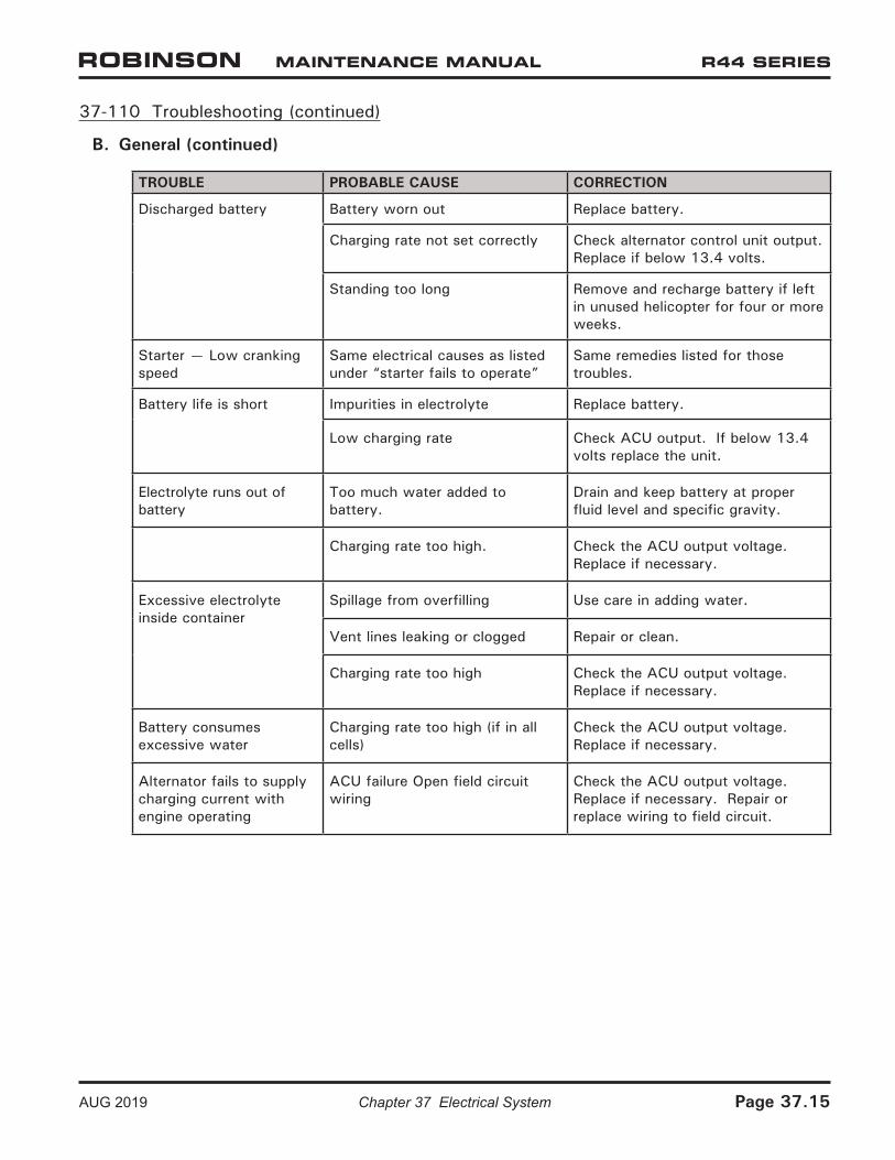
37-110 Troubleshooting (continued)
B. General (continued)
TROUBLE PROBABLE CAUSE CORRECTION
Discharged battery Battery worn out Replace battery.
Charging rate not set correctly Check alternator control unit output. Replace if below 13.4 volts.
Standing too long Remove and recharge battery if left in unused helicopter for four or more weeks.
Starter — Low cranking speed
Same electrical causes as listed under “starter fails to operate”
Same remedies listed for those troubles.
Battery life is short Impurities in electrolyte Replace battery.
Low charging rate Check ACU output. If below 13.4 volts replace the unit.
Electrolyte runs out of battery
Too much water added to battery.
Drain and keep battery at proper fluid level and specific gravity.
Charging rate too high. Check the ACU output voltage. Replace if necessary.
Excessive electrolyte inside container
Spillage from overfilling Use care in adding water.
Vent lines leaking or clogged Repair or clean.
Charging rate too high Check the ACU output voltage. Replace if necessary.
Battery consumes excessive water
Charging rate too high (if in all cells)
Check the ACU output voltage. Replace if necessary.
Alternator fails to supply charging current with engine operating
ACU failure Open field circuit wiring
Check the ACU output voltage. Replace if necessary. Repair or replace wiring to field circuit.
Page 37.16 Chapter 37 Electrical System AUG 2019
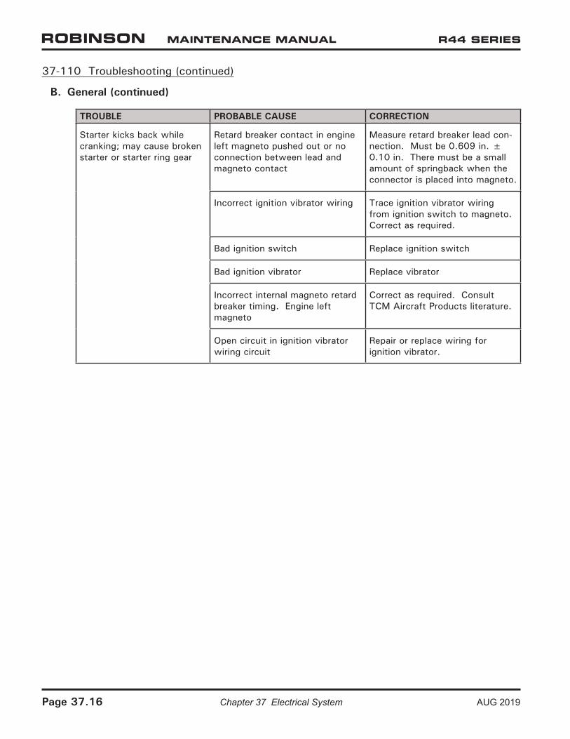
37-110 Troubleshooting (continued)
B. General (continued)
TROUBLE PROBABLE CAUSE CORRECTION
Starter kicks back while cranking; may cause broken starter or starter ring gear
Retard breaker contact in engine left magneto pushed out or no connection between lead and magneto contact
Measure retard breaker lead con-nection. Must be 0.609 in. ± 0.10 in. There must be a small amount of springback when the connector is placed into magneto.
Incorrect ignition vibrator wiring Trace ignition vibrator wiring from ignition switch to magneto. Correct as required.
Bad ignition switch Replace ignition switch
Bad ignition vibrator Replace vibrator
Incorrect internal magneto retard breaker timing. Engine left magneto
Correct as required. Consult TCM Aircraft Products literature.
Open circuit in ignition vibrator wiring circuit
Repair or replace wiring for ignition vibrator.
AUG 2019 Chapter 37 Electrical System Page 37.17
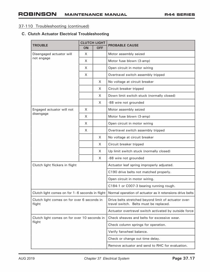
37-110 Troubleshooting (continued)
C. Clutch Actuator Electrical Troubleshooting
TROUBLECLUTCH LIGHT
PROBABLE CAUSEON OFF
Disengaged actuator will not engage
X Motor assembly seized
X Motor fuse blown (3-amp)
X Open circuit in motor wiring
X Overtravel switch assembly tripped
X No voltage at circuit breaker
X Circuit breaker tripped
X Down limit switch stuck (normally closed)
X -88 wire not grounded
Engaged actuator will not disengage
X Motor assembly seized
X Motor fuse blown (3-amp)
X Open circuit in motor wiring
X Overtravel switch assembly tripped
X No voltage at circuit breaker
X Circuit breaker tripped
X Up limit switch stuck (normally closed)
X -88 wire not grounded
Clutch light flickers in flight Actuator leaf spring improperly adjusted.
C190 drive belts not matched properly.
Open circuit in motor wiring.
C184-1 or C007-3 bearing running rough.
Clutch light comes on for 1–6 seconds in flight Normal operation of actuator as it retensions drive belts
Clutch light comes on for over 6 seconds in flight
Drive belts stretched beyond limit of actuator over-travel switch. Belts must be replaced.
Actuator overtravel switch activated by outside force
Clutch light comes on for over 10 seconds in flight
Check sheaves and belts for excessive wear.
Check column springs for operation.
Verify fanwheel balance.
Check or change out time delay.
Remove actuator and send to RHC for evaluation.
Page 37.18 Chapter 37 Electrical System AUG 2019
37-110 Troubleshooting (continued)
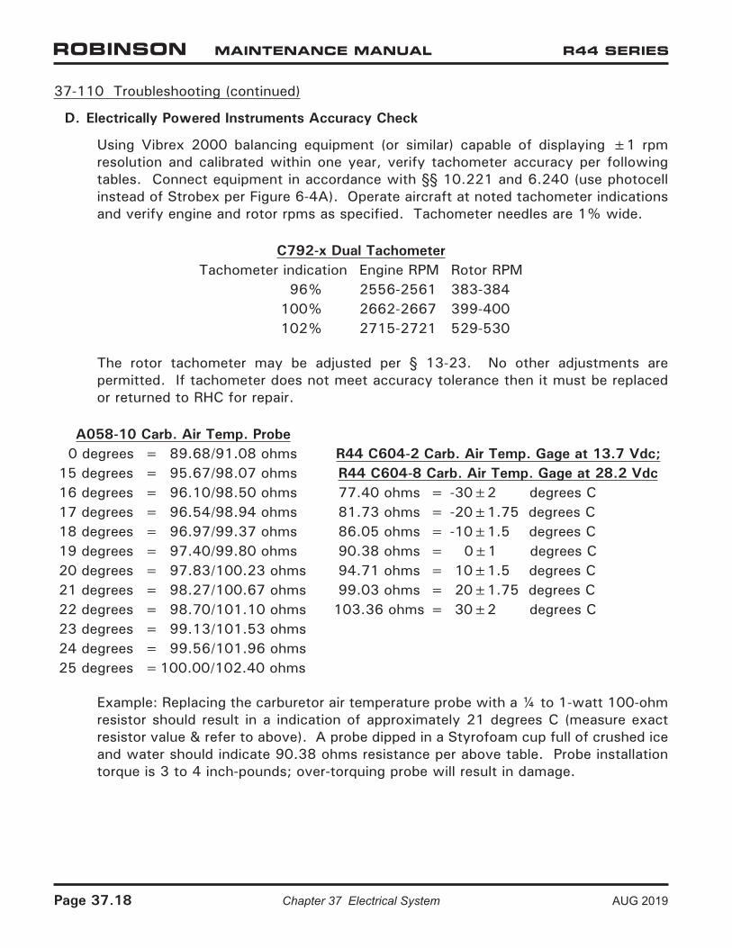
D. Electrically Powered Instruments Accuracy Check
Using Vibrex 2000 balancing equipment (or similar) capable of displaying ±1 rpm resolution and calibrated within one year, verify tachometer accuracy per following tables. Connect equipment in accordance with §§ 10.221 and 6.240 (use photocell instead of Strobex per Figure 6-4A). Operate aircraft at noted tachometer indications and verify engine and rotor rpms as specified. Tachometer needles are 1% wide.
C792-x Dual TachometerTachometer indication Engine RPM Rotor RPM
96% 2556-2561 383-384100% 2662-2667 399-400102% 2715-2721 529-530
The rotor tachometer may be adjusted per § 13-23. No other adjustments are permitted. If tachometer does not meet accuracy tolerance then it must be replaced or returned to RHC for repair.
A058-10 Carb. Air Temp. Probe 0 degrees = 89.68/91.08 ohms R44 C604-2 Carb. Air Temp. Gage at 13.7 Vdc;15 degrees = 95.67/98.07 ohms R44 C604-8 Carb. Air Temp. Gage at 28.2 Vdc16 degrees = 96.10/98.50 ohms 77.40 ohms = -30±2 degrees C17 degrees = 96.54/98.94 ohms 81.73 ohms = -20±1.75 degrees C18 degrees = 96.97/99.37 ohms 86.05 ohms = -10±1.5 degrees C19 degrees = 97.40/99.80 ohms 90.38 ohms = 0±1 degrees C20 degrees = 97.83/100.23 ohms 94.71 ohms = 10±1.5 degrees C21 degrees = 98.27/100.67 ohms 99.03 ohms = 20±1.75 degrees C22 degrees = 98.70/101.10 ohms 103.36 ohms = 30±2 degrees C23 degrees = 99.13/101.53 ohms24 degrees = 99.56/101.96 ohms25 degrees =100.00/102.40 ohms
Example: Replacing the carburetor air temperature probe with a ¼ to 1-watt 100-ohm resistor should result in a indication of approximately 21 degrees C (measure exact resistor value & refer to above). A probe dipped in a Styrofoam cup full of crushed ice and water should indicate 90.38 ohms resistance per above table. Probe installation torque is 3 to 4 inch-pounds; over-torquing probe will result in damage.
AUG 2019 Chapter 37 Electrical System Page 37.19
37-110 Troubleshooting (continued)
D. Electrically Powered Instruments Accuracy Check (continued)
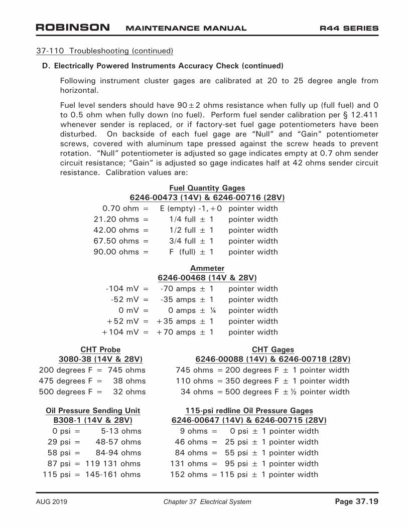
Following instrument cluster gages are calibrated at 20 to 25 degree angle from horizontal.
Fuel level senders should have 90±2 ohms resistance when fully up (full fuel) and 0 to 0.5 ohm when fully down (no fuel). Perform fuel sender calibration per § 12.411 whenever sender is replaced, or if factory-set fuel gage potentiometers have been disturbed. On backside of each fuel gage are “Null” and “Gain” potentiometer screws, covered with aluminum tape pressed against the screw heads to prevent rotation. “Null” potentiometer is adjusted so gage indicates empty at 0.7 ohm sender circuit resistance; “Gain” is adjusted so gage indicates half at 42 ohms sender circuit resistance. Calibration values are:
Fuel Quantity Gages6246-00473 (14V) & 6246-00716 (28V)
0.70 ohm = E (empty) -1,+0 pointer width21.20 ohms = 1/4 full ± 1 pointer width42.00 ohms = 1/2 full ± 1 pointer width67.50 ohms = 3/4 full ± 1 pointer width90.00 ohms = F (full) ± 1 pointer width
Ammeter6246-00468 (14V & 28V)
-104 mV = -70 amps ± 1 pointer width-52 mV = -35 amps ± 1 pointer width
0 mV = 0 amps ± ¼ pointer width+52 mV = +35 amps ± 1 pointer width
+104 mV = +70 amps ± 1 pointer width
CHT Probe3080-38 (14V & 28V)
CHT Gages6246-00088 (14V) & 6246-00718 (28V)
200 degrees F = 745 ohms 745 ohms =200 degrees F ± 1 pointer width475 degrees F = 38 ohms 110 ohms =350 degrees F ± 1 pointer width500 degrees F = 32 ohms 34 ohms =500 degrees F ±½ pointer width
Oil Pressure Sending UnitB308-1 (14V & 28V)
115-psi redline Oil Pressure Gages6246-00647 (14V) & 6246-00715 (28V)
0 psi = 5-13 ohms 9 ohms = 0 psi ± 1 pointer width29 psi = 48-57 ohms 46 ohms = 25 psi ± 1 pointer width58 psi = 84-94 ohms 84 ohms = 55 psi ± 1 pointer width87 psi = 119 131 ohms 131 ohms = 95 psi ± 1 pointer width
115 psi = 145-161 ohms 152 ohms =115 psi ± 1 pointer width
Page 37.20 Chapter 37 Electrical System AUG 2019
37-110 Troubleshooting (continued)
D. Electrically Powered Instruments Accuracy Check (continued)
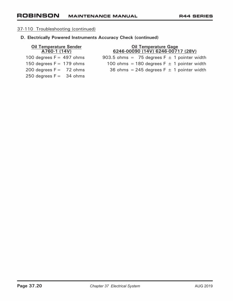
Oil Temperature SenderA760-1 (14V)
Oil Temperature Gage6246-00090 (14V) 6246-00717 (28V)
100 degrees F= 497 ohms 903.5 ohms = 75 degrees F ± 1 pointer width150 degrees F= 179 ohms 100 ohms =180 degrees F ± 1 pointer width200 degrees F= 72 ohms 36 ohms =245 degrees F ± 1 pointer width250 degrees F= 34 ohms
AUG 2019 Chapter 37 Electrical System Page 37.21
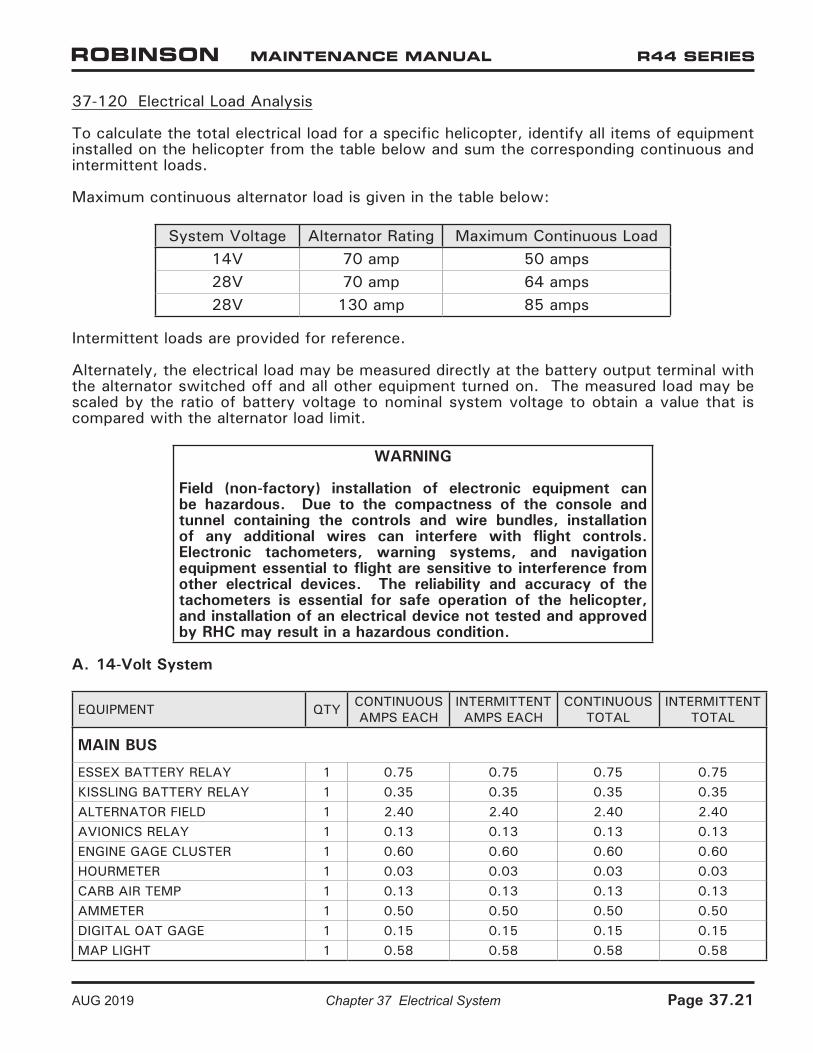
37-120 Electrical Load Analysis
To calculate the total electrical load for a specific helicopter, identify all items of equipment installed on the helicopter from the table below and sum the corresponding continuous and intermittent loads.
Maximum continuous alternator load is given in the table below:
System Voltage Alternator Rating Maximum Continuous Load14V 70 amp 50 amps28V 70 amp 64 amps28V 130 amp 85 amps
Intermittent loads are provided for reference.
Alternately, the electrical load may be measured directly at the battery output terminal with the alternator switched off and all other equipment turned on. The measured load may be scaled by the ratio of battery voltage to nominal system voltage to obtain a value that is compared with the alternator load limit.
WARNING
Field (non-factory) installation of electronic equipment can be hazardous. Due to the compactness of the console and tunnel containing the controls and wire bundles, installation of any additional wires can interfere with flight controls. Electronic tachometers, warning systems, and navigation equipment essential to flight are sensitive to interference from other electrical devices. The reliability and accuracy of the tachometers is essential for safe operation of the helicopter, and installation of an electrical device not tested and approved by RHC may result in a hazardous condition.
A. 14-Volt System
EQUIPMENT QTY CONTINUOUS AMPS EACH
INTERMITTENT AMPS EACH
CONTINUOUS TOTAL
INTERMITTENT TOTAL
MAIN BUS
ESSEX BATTERY RELAY 1 0.75 0.75 0.75 0.75KISSLING BATTERY RELAY 1 0.35 0.35 0.35 0.35ALTERNATOR FIELD 1 2.40 2.40 2.40 2.40AVIONICS RELAY 1 0.13 0.13 0.13 0.13ENGINE GAGE CLUSTER 1 0.60 0.60 0.60 0.60HOURMETER 1 0.03 0.03 0.03 0.03CARB AIR TEMP 1 0.13 0.13 0.13 0.13AMMETER 1 0.50 0.50 0.50 0.50DIGITAL OAT GAGE 1 0.15 0.15 0.15 0.15MAP LIGHT 1 0.58 0.58 0.58 0.58
Page 37.22 Chapter 37 Electrical System AUG 2019
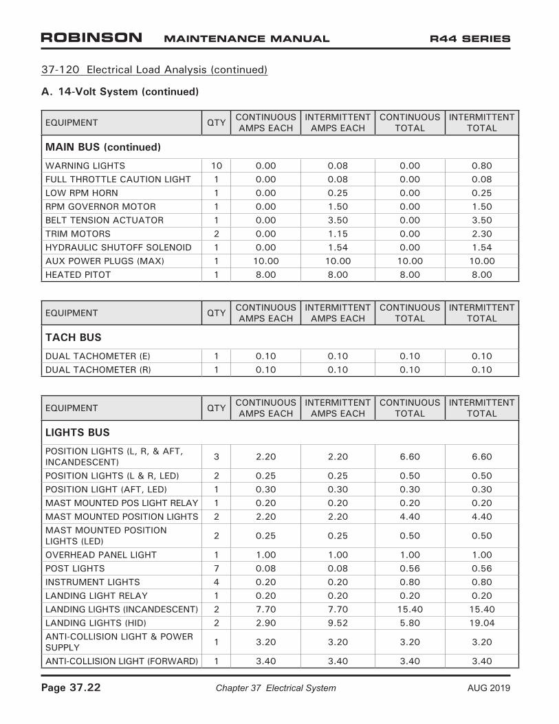
37-120 Electrical Load Analysis (continued)
A. 14-Volt System (continued)
EQUIPMENT QTY CONTINUOUS AMPS EACH
INTERMITTENT AMPS EACH
CONTINUOUS TOTAL
INTERMITTENT TOTAL
MAIN BUS (continued)
WARNING LIGHTS 10 0.00 0.08 0.00 0.80FULL THROTTLE CAUTION LIGHT 1 0.00 0.08 0.00 0.08LOW RPM HORN 1 0.00 0.25 0.00 0.25RPM GOVERNOR MOTOR 1 0.00 1.50 0.00 1.50BELT TENSION ACTUATOR 1 0.00 3.50 0.00 3.50TRIM MOTORS 2 0.00 1.15 0.00 2.30HYDRAULIC SHUTOFF SOLENOID 1 0.00 1.54 0.00 1.54AUX POWER PLUGS (MAX) 1 10.00 10.00 10.00 10.00HEATED PITOT 1 8.00 8.00 8.00 8.00
EQUIPMENT QTY CONTINUOUS AMPS EACH
INTERMITTENT AMPS EACH
CONTINUOUS TOTAL
INTERMITTENT TOTAL
TACH BUS
DUAL TACHOMETER (E) 1 0.10 0.10 0.10 0.10DUAL TACHOMETER (R) 1 0.10 0.10 0.10 0.10
EQUIPMENT QTY CONTINUOUS AMPS EACH
INTERMITTENT AMPS EACH
CONTINUOUS TOTAL
INTERMITTENT TOTAL
LIGHTS BUS
POSITION LIGHTS (L, R, & AFT, INCANDESCENT) 3 2.20 2.20 6.60 6.60
POSITION LIGHTS (L & R, LED) 2 0.25 0.25 0.50 0.50POSITION LIGHT (AFT, LED) 1 0.30 0.30 0.30 0.30MAST MOUNTED POS LIGHT RELAY 1 0.20 0.20 0.20 0.20MAST MOUNTED POSITION LIGHTS 2 2.20 2.20 4.40 4.40MAST MOUNTED POSITION LIGHTS (LED) 2 0.25 0.25 0.50 0.50
OVERHEAD PANEL LIGHT 1 1.00 1.00 1.00 1.00POST LIGHTS 7 0.08 0.08 0.56 0.56INSTRUMENT LIGHTS 4 0.20 0.20 0.80 0.80LANDING LIGHT RELAY 1 0.20 0.20 0.20 0.20LANDING LIGHTS (INCANDESCENT) 2 7.70 7.70 15.40 15.40LANDING LIGHTS (HID) 2 2.90 9.52 5.80 19.04ANTI-COLLISION LIGHT & POWER SUPPLY 1 3.20 3.20 3.20 3.20
ANTI-COLLISION LIGHT (FORWARD) 1 3.40 3.40 3.40 3.40
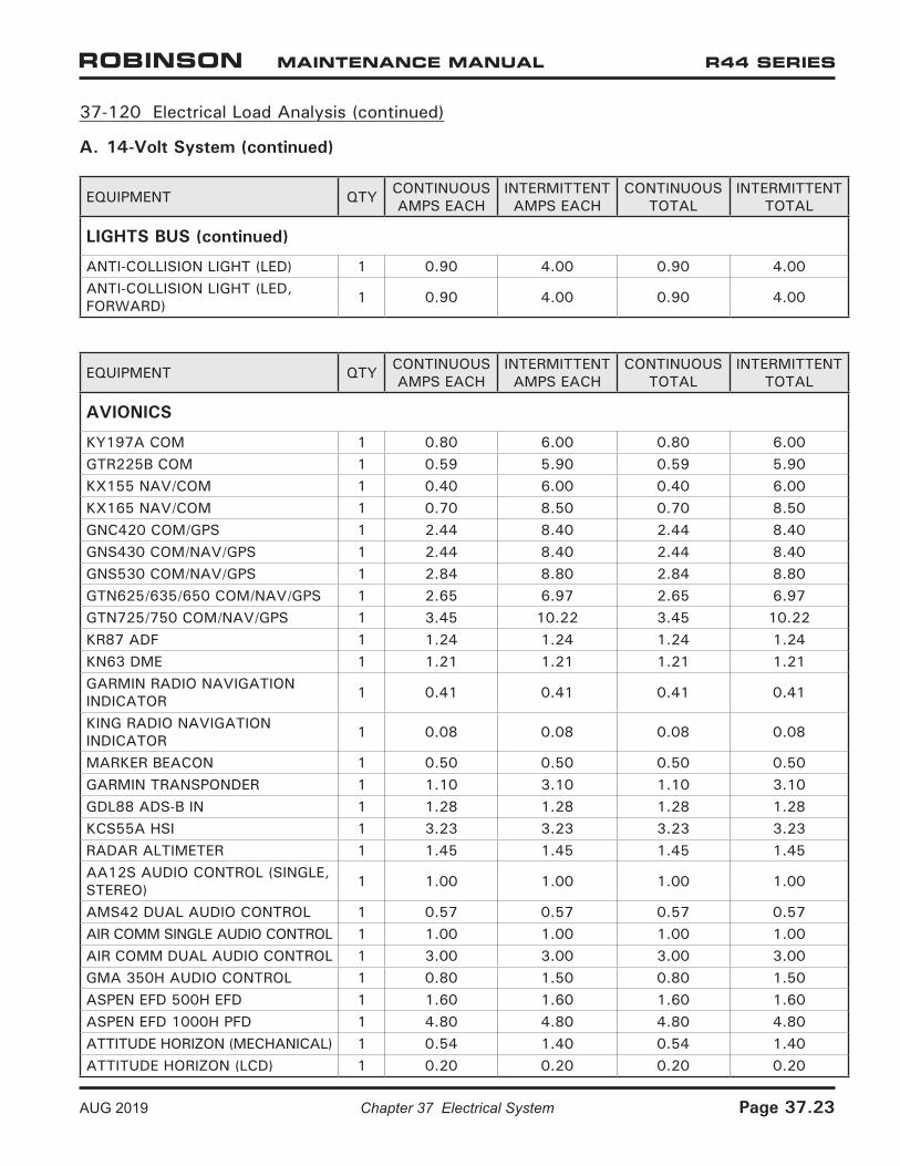
37-120 Electrical Load Analysis (continued)
A. 14-Volt System (continued)
EQUIPMENT QTY CONTINUOUS AMPS EACH
INTERMITTENT AMPS EACH
CONTINUOUS TOTAL
INTERMITTENT TOTAL
LIGHTS BUS (continued)
ANTI-COLLISION LIGHT (LED) 1 0.90 4.00 0.90 4.00ANTI-COLLISION LIGHT (LED, FORWARD) 1 0.90 4.00 0.90 4.00
EQUIPMENT QTY CONTINUOUS AMPS EACH
INTERMITTENT AMPS EACH
CONTINUOUS TOTAL
INTERMITTENT TOTAL
AVIONICS
KY197A COM 1 0.80 6.00 0.80 6.00GTR225B COM 1 0.59 5.90 0.59 5.90KX155 NAV/COM 1 0.40 6.00 0.40 6.00KX165 NAV/COM 1 0.70 8.50 0.70 8.50GNC420 COM/GPS 1 2.44 8.40 2.44 8.40GNS430 COM/NAV/GPS 1 2.44 8.40 2.44 8.40GNS530 COM/NAV/GPS 1 2.84 8.80 2.84 8.80GTN625/635/650 COM/NAV/GPS 1 2.65 6.97 2.65 6.97GTN725/750 COM/NAV/GPS 1 3.45 10.22 3.45 10.22KR87 ADF 1 1.24 1.24 1.24 1.24KN63 DME 1 1.21 1.21 1.21 1.21GARMIN RADIO NAVIGATION INDICATOR 1 0.41 0.41 0.41 0.41
KING RADIO NAVIGATION INDICATOR 1 0.08 0.08 0.08 0.08
MARKER BEACON 1 0.50 0.50 0.50 0.50GARMIN TRANSPONDER 1 1.10 3.10 1.10 3.10GDL88 ADS-B IN 1 1.28 1.28 1.28 1.28KCS55A HSI 1 3.23 3.23 3.23 3.23RADAR ALTIMETER 1 1.45 1.45 1.45 1.45AA12S AUDIO CONTROL (SINGLE, STEREO) 1 1.00 1.00 1.00 1.00
AMS42 DUAL AUDIO CONTROL 1 0.57 0.57 0.57 0.57AIR COMM SINGLE AUDIO CONTROL 1 1.00 1.00 1.00 1.00AIR COMM DUAL AUDIO CONTROL 1 3.00 3.00 3.00 3.00GMA 350H AUDIO CONTROL 1 0.80 1.50 0.80 1.50ASPEN EFD 500H EFD 1 1.60 1.60 1.60 1.60ASPEN EFD 1000H PFD 1 4.80 4.80 4.80 4.80ATTITUDE HORIZON (MECHANICAL) 1 0.54 1.40 0.54 1.40ATTITUDE HORIZON (LCD) 1 0.20 0.20 0.20 0.20
AUG 2019 Chapter 37 Electrical System Page 37.23
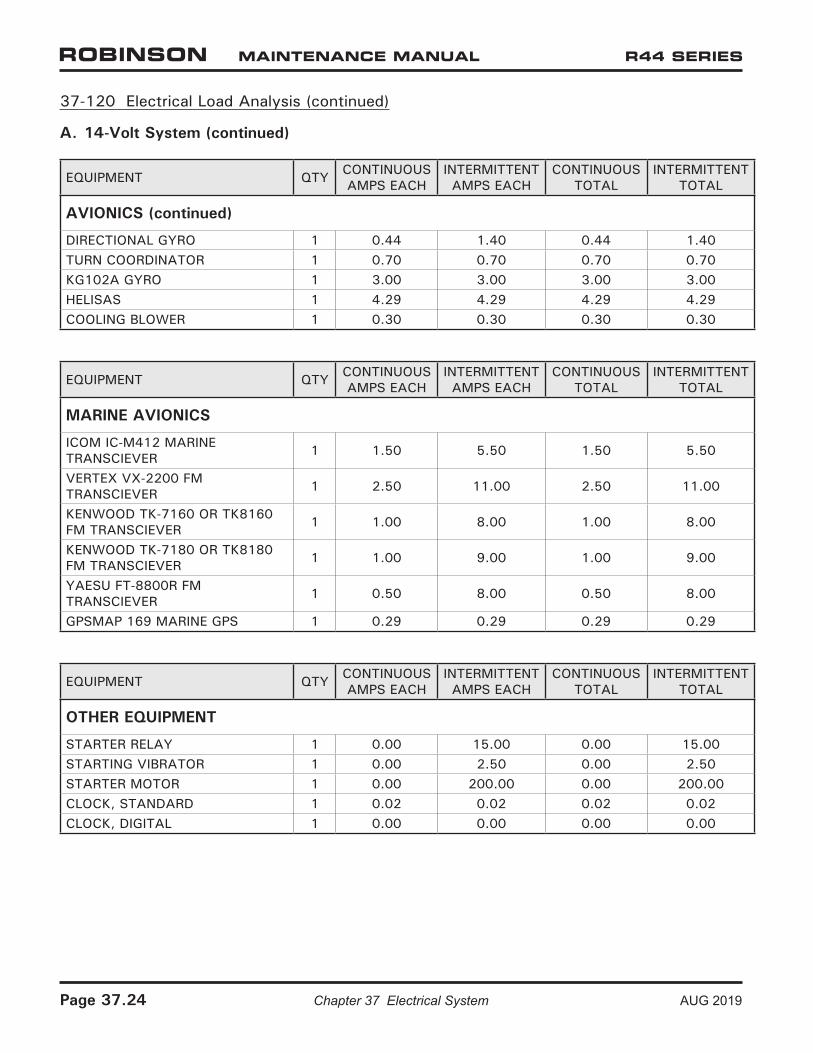
37-120 Electrical Load Analysis (continued)
A. 14-Volt System (continued)
EQUIPMENT QTY CONTINUOUS AMPS EACH
INTERMITTENT AMPS EACH
CONTINUOUS TOTAL
INTERMITTENT TOTAL
AVIONICS (continued)
DIRECTIONAL GYRO 1 0.44 1.40 0.44 1.40TURN COORDINATOR 1 0.70 0.70 0.70 0.70KG102A GYRO 1 3.00 3.00 3.00 3.00HELISAS 1 4.29 4.29 4.29 4.29COOLING BLOWER 1 0.30 0.30 0.30 0.30
EQUIPMENT QTY CONTINUOUS AMPS EACH
INTERMITTENT AMPS EACH
CONTINUOUS TOTAL
INTERMITTENT TOTAL
MARINE AVIONICS
ICOM IC-M412 MARINE TRANSCIEVER 1 1.50 5.50 1.50 5.50
VERTEX VX-2200 FM TRANSCIEVER 1 2.50 11.00 2.50 11.00
KENWOOD TK-7160 OR TK8160 FM TRANSCIEVER 1 1.00 8.00 1.00 8.00
KENWOOD TK-7180 OR TK8180 FM TRANSCIEVER 1 1.00 9.00 1.00 9.00
YAESU FT-8800R FM TRANSCIEVER 1 0.50 8.00 0.50 8.00
GPSMAP 169 MARINE GPS 1 0.29 0.29 0.29 0.29
EQUIPMENT QTY CONTINUOUS AMPS EACH
INTERMITTENT AMPS EACH
CONTINUOUS TOTAL
INTERMITTENT TOTAL
OTHER EQUIPMENT
STARTER RELAY 1 0.00 15.00 0.00 15.00STARTING VIBRATOR 1 0.00 2.50 0.00 2.50STARTER MOTOR 1 0.00 200.00 0.00 200.00CLOCK, STANDARD 1 0.02 0.02 0.02 0.02CLOCK, DIGITAL 1 0.00 0.00 0.00 0.00
Page 37.24 Chapter 37 Electrical System AUG 2019
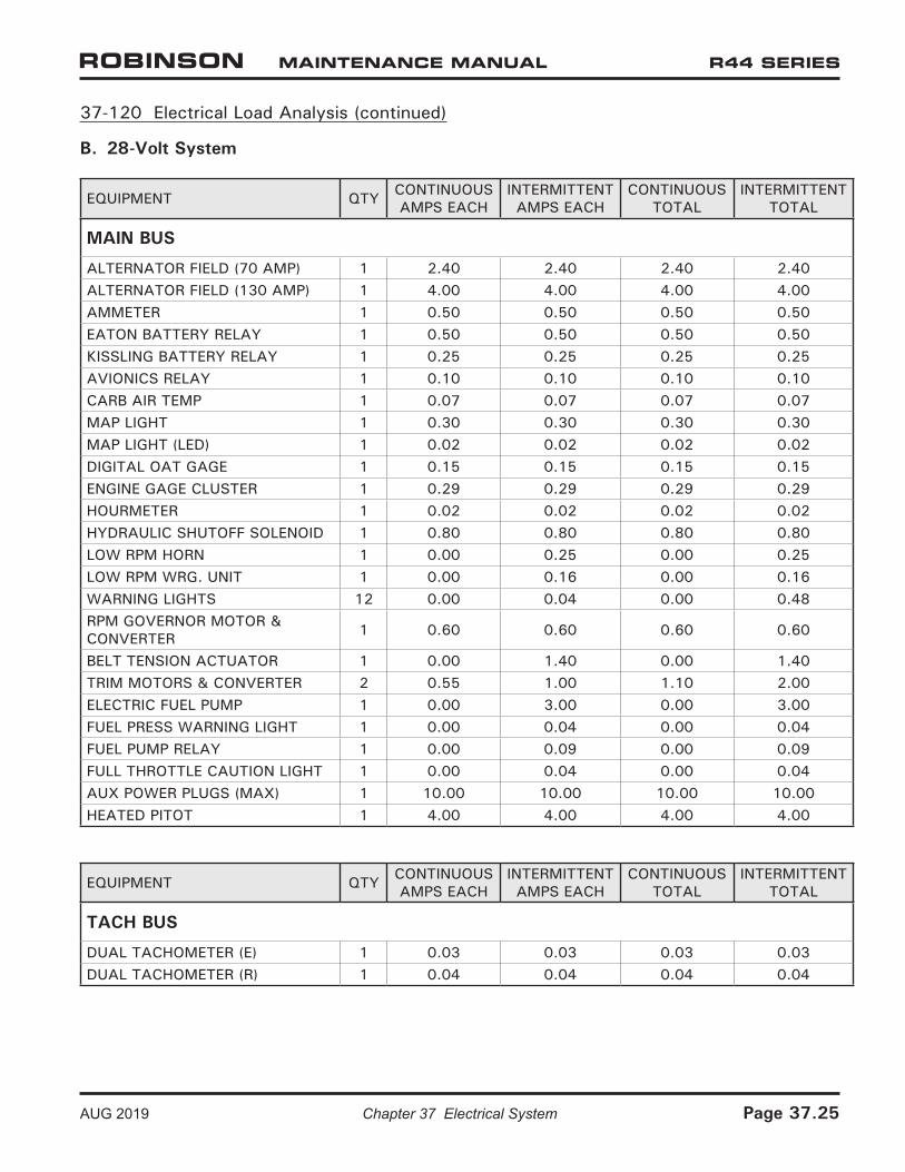
37-120 Electrical Load Analysis (continued)
B. 28-Volt System
EQUIPMENT QTY CONTINUOUS AMPS EACH
INTERMITTENT AMPS EACH
CONTINUOUS TOTAL
INTERMITTENT TOTAL
MAIN BUS
ALTERNATOR FIELD (70 AMP) 1 2.40 2.40 2.40 2.40ALTERNATOR FIELD (130 AMP) 1 4.00 4.00 4.00 4.00AMMETER 1 0.50 0.50 0.50 0.50EATON BATTERY RELAY 1 0.50 0.50 0.50 0.50KISSLING BATTERY RELAY 1 0.25 0.25 0.25 0.25AVIONICS RELAY 1 0.10 0.10 0.10 0.10CARB AIR TEMP 1 0.07 0.07 0.07 0.07MAP LIGHT 1 0.30 0.30 0.30 0.30MAP LIGHT (LED) 1 0.02 0.02 0.02 0.02DIGITAL OAT GAGE 1 0.15 0.15 0.15 0.15ENGINE GAGE CLUSTER 1 0.29 0.29 0.29 0.29HOURMETER 1 0.02 0.02 0.02 0.02HYDRAULIC SHUTOFF SOLENOID 1 0.80 0.80 0.80 0.80LOW RPM HORN 1 0.00 0.25 0.00 0.25LOW RPM WRG. UNIT 1 0.00 0.16 0.00 0.16WARNING LIGHTS 12 0.00 0.04 0.00 0.48RPM GOVERNOR MOTOR & CONVERTER 1 0.60 0.60 0.60 0.60
BELT TENSION ACTUATOR 1 0.00 1.40 0.00 1.40TRIM MOTORS & CONVERTER 2 0.55 1.00 1.10 2.00ELECTRIC FUEL PUMP 1 0.00 3.00 0.00 3.00FUEL PRESS WARNING LIGHT 1 0.00 0.04 0.00 0.04FUEL PUMP RELAY 1 0.00 0.09 0.00 0.09FULL THROTTLE CAUTION LIGHT 1 0.00 0.04 0.00 0.04AUX POWER PLUGS (MAX) 1 10.00 10.00 10.00 10.00HEATED PITOT 1 4.00 4.00 4.00 4.00
EQUIPMENT QTY CONTINUOUS AMPS EACH
INTERMITTENT AMPS EACH
CONTINUOUS TOTAL
INTERMITTENT TOTAL
TACH BUS
DUAL TACHOMETER (E) 1 0.03 0.03 0.03 0.03DUAL TACHOMETER (R) 1 0.04 0.04 0.04 0.04
AUG 2019 Chapter 37 Electrical System Page 37.25
37-120 Electrical Load Analysis (continued)
B. 28-Volt System (continued)
EQUIPMENT QTY CONTINUOUS AMPS EACH
INTERMITTENT AMPS EACH
CONTINUOUS TOTAL
INTERMITTENT TOTAL
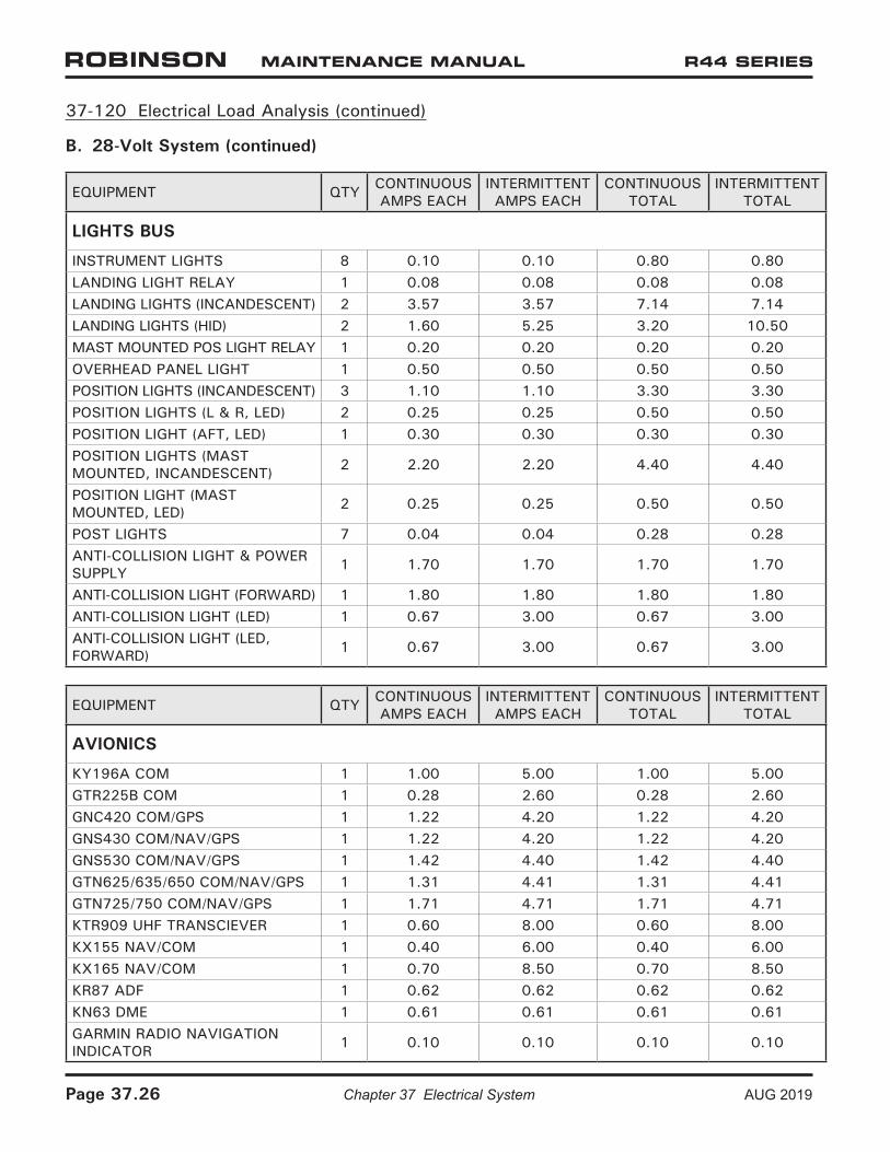
LIGHTS BUS
INSTRUMENT LIGHTS 8 0.10 0.10 0.80 0.80LANDING LIGHT RELAY 1 0.08 0.08 0.08 0.08LANDING LIGHTS (INCANDESCENT) 2 3.57 3.57 7.14 7.14LANDING LIGHTS (HID) 2 1.60 5.25 3.20 10.50MAST MOUNTED POS LIGHT RELAY 1 0.20 0.20 0.20 0.20OVERHEAD PANEL LIGHT 1 0.50 0.50 0.50 0.50POSITION LIGHTS (INCANDESCENT) 3 1.10 1.10 3.30 3.30POSITION LIGHTS (L & R, LED) 2 0.25 0.25 0.50 0.50POSITION LIGHT (AFT, LED) 1 0.30 0.30 0.30 0.30POSITION LIGHTS (MAST MOUNTED, INCANDESCENT) 2 2.20 2.20 4.40 4.40
POSITION LIGHT (MAST MOUNTED, LED) 2 0.25 0.25 0.50 0.50
POST LIGHTS 7 0.04 0.04 0.28 0.28ANTI-COLLISION LIGHT & POWER SUPPLY 1 1.70 1.70 1.70 1.70
ANTI-COLLISION LIGHT (FORWARD) 1 1.80 1.80 1.80 1.80ANTI-COLLISION LIGHT (LED) 1 0.67 3.00 0.67 3.00ANTI-COLLISION LIGHT (LED, FORWARD) 1 0.67 3.00 0.67 3.00
EQUIPMENT QTY CONTINUOUS AMPS EACH
INTERMITTENT AMPS EACH
CONTINUOUS TOTAL
INTERMITTENT TOTAL
AVIONICS
KY196A COM 1 1.00 5.00 1.00 5.00GTR225B COM 1 0.28 2.60 0.28 2.60GNC420 COM/GPS 1 1.22 4.20 1.22 4.20GNS430 COM/NAV/GPS 1 1.22 4.20 1.22 4.20GNS530 COM/NAV/GPS 1 1.42 4.40 1.42 4.40GTN625/635/650 COM/NAV/GPS 1 1.31 4.41 1.31 4.41GTN725/750 COM/NAV/GPS 1 1.71 4.71 1.71 4.71KTR909 UHF TRANSCIEVER 1 0.60 8.00 0.60 8.00KX155 NAV/COM 1 0.40 6.00 0.40 6.00KX165 NAV/COM 1 0.70 8.50 0.70 8.50KR87 ADF 1 0.62 0.62 0.62 0.62KN63 DME 1 0.61 0.61 0.61 0.61GARMIN RADIO NAVIGATION INDICATOR 1 0.10 0.10 0.10 0.10
Page 37.26 Chapter 37 Electrical System AUG 2019
37-120 Electrical Load Analysis (continued)
B. 28-Volt System (continued)
EQUIPMENT QTY CONTINUOUS AMPS EACH
INTERMITTENT AMPS EACH
CONTINUOUS TOTAL
INTERMITTENT TOTAL
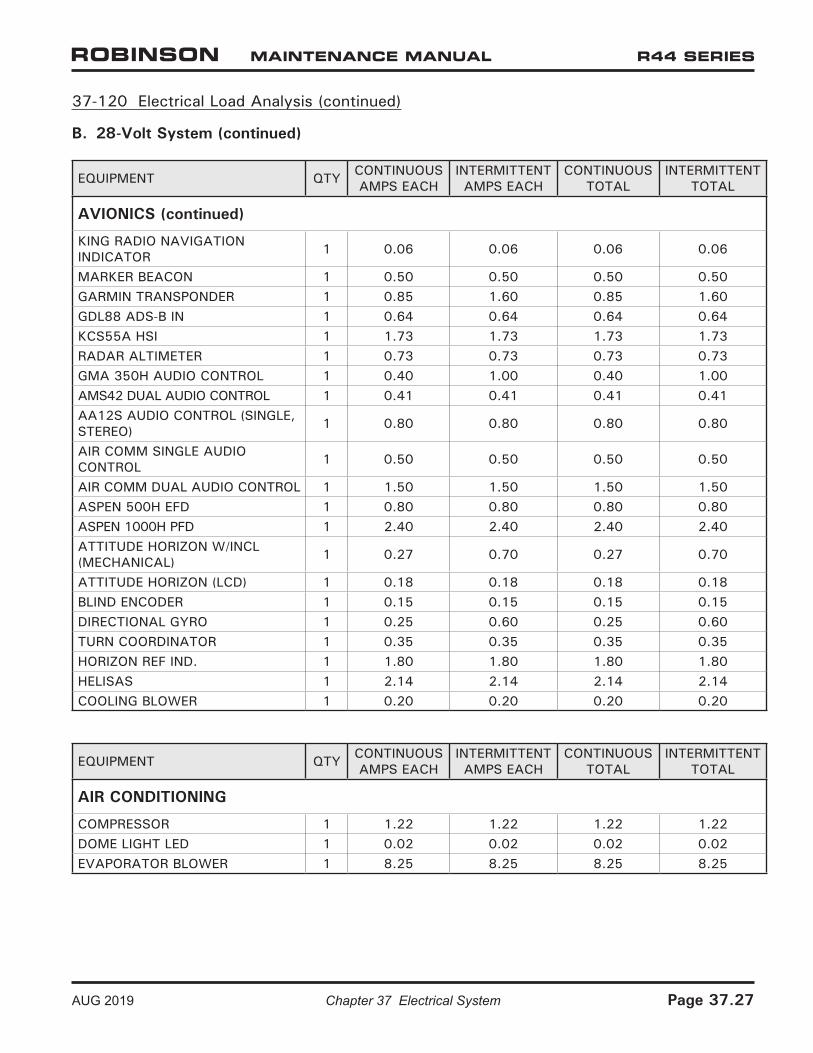
AVIONICS (continued)
KING RADIO NAVIGATION INDICATOR 1 0.06 0.06 0.06 0.06
MARKER BEACON 1 0.50 0.50 0.50 0.50GARMIN TRANSPONDER 1 0.85 1.60 0.85 1.60GDL88 ADS-B IN 1 0.64 0.64 0.64 0.64KCS55A HSI 1 1.73 1.73 1.73 1.73RADAR ALTIMETER 1 0.73 0.73 0.73 0.73GMA 350H AUDIO CONTROL 1 0.40 1.00 0.40 1.00AMS42 DUAL AUDIO CONTROL 1 0.41 0.41 0.41 0.41AA12S AUDIO CONTROL (SINGLE, STEREO) 1 0.80 0.80 0.80 0.80
AIR COMM SINGLE AUDIO CONTROL 1 0.50 0.50 0.50 0.50
AIR COMM DUAL AUDIO CONTROL 1 1.50 1.50 1.50 1.50ASPEN 500H EFD 1 0.80 0.80 0.80 0.80ASPEN 1000H PFD 1 2.40 2.40 2.40 2.40ATTITUDE HORIZON W/INCL (MECHANICAL) 1 0.27 0.70 0.27 0.70
ATTITUDE HORIZON (LCD) 1 0.18 0.18 0.18 0.18BLIND ENCODER 1 0.15 0.15 0.15 0.15DIRECTIONAL GYRO 1 0.25 0.60 0.25 0.60TURN COORDINATOR 1 0.35 0.35 0.35 0.35HORIZON REF IND. 1 1.80 1.80 1.80 1.80HELISAS 1 2.14 2.14 2.14 2.14COOLING BLOWER 1 0.20 0.20 0.20 0.20
EQUIPMENT QTY CONTINUOUS AMPS EACH
INTERMITTENT AMPS EACH
CONTINUOUS TOTAL
INTERMITTENT TOTAL
AIR CONDITIONING
COMPRESSOR 1 1.22 1.22 1.22 1.22DOME LIGHT LED 1 0.02 0.02 0.02 0.02EVAPORATOR BLOWER 1 8.25 8.25 8.25 8.25
AUG 2019 Chapter 37 Electrical System Page 37.27
37-120 Electrical Load Analysis (continued)
B. 28-Volt System (continued)
EQUIPMENT QTY CONTINUOUS AMPS EACH
INTERMITTENT AMPS EACH
CONTINUOUS TOTAL
INTERMITTENT TOTAL
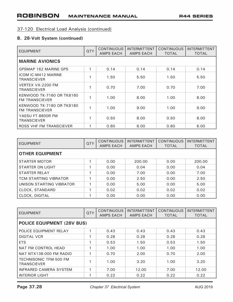
MARINE AVIONICS
GPSMAP 162 MARINE GPS 1 0.14 0.14 0.14 0.14ICOM IC-M412 MARINE TRANSCIEVER 1 1.50 5.50 1.50 5.50
VERTEX VX-2200 FM TRANSCIEVER 1 0.70 7.00 0.70 7.00
KENWOOD TK-7160 OR TK8160 FM TRANSCIEVER 1 1.00 8.00 1.00 8.00
KENWOOD TK-7180 OR TK8180 FM TRANSCIEVER 1 1.00 9.00 1.00 9.00
YAESU FT-8800R FM TRANSCIEVER 1 0.50 8.00 0.50 8.00
ROSS VHF FM TRANSCIEVER 1 0.60 6.00 0.60 6.00
EQUIPMENT QTY CONTINUOUS AMPS EACH
INTERMITTENT AMPS EACH
CONTINUOUS TOTAL
INTERMITTENT TOTAL
OTHER EQUIPMENT
STARTER MOTOR 1 0.00 200.00 0.00 200.00STARTER ON LIGHT 1 0.00 0.04 0.00 0.04STARTER RELAY 1 0.00 7.00 0.00 7.00TCM STARTING VIBRATOR 1 0.00 2.50 0.00 2.50UNISON STARTING VIBRATOR 1 0.00 5.00 0.00 5.00CLOCK, STANDARD 1 0.02 0.02 0.02 0.02CLOCK, DIGITAL 1 0.00 0.00 0.00 0.00
EQUIPMENT QTY CONTINUOUS AMPS EACH
INTERMITTENT AMPS EACH
CONTINUOUS TOTAL
INTERMITTENT TOTAL
POLICE EQUIPMENT (28V BUS)
POLICE EQUIPMENT RELAY 1 0.43 0.43 0.43 0.43DIGITAL VCR 1 0.28 0.28 0.28 0.28ETS 1 0.53 1.50 0.53 1.50NAT FM CONTROL HEAD 1 1.00 1.00 1.00 1.00NAT NTX138-000 FM RADIO 1 0.70 2.00 0.70 2.00TECHNISONIC TFM-500 FM TRANSCIEVER 1 1.00 3.20 1.00 3.20
INFRARED CAMERA SYSTEM 1 7.00 12.00 7.00 12.00INTERIOR LIGHT 1 0.22 0.22 0.22 0.22
Page 37.28 Chapter 37 Electrical System AUG 2019
37-120 Electrical Load Analysis (continued)
B. 28-Volt System (continued)
EQUIPMENT QTY CONTINUOUS AMPS EACH
INTERMITTENT AMPS EACH
CONTINUOUS TOTAL
INTERMITTENT TOTAL
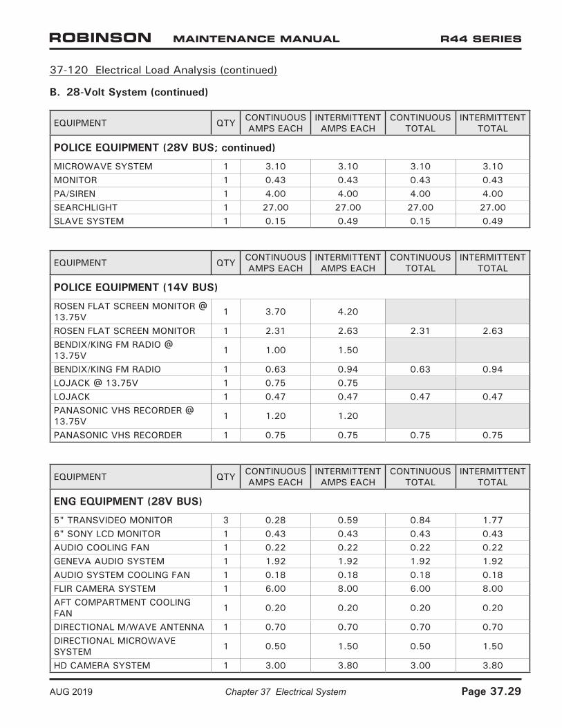
POLICE EQUIPMENT (28V BUS; continued)
MICROWAVE SYSTEM 1 3.10 3.10 3.10 3.10MONITOR 1 0.43 0.43 0.43 0.43PA/SIREN 1 4.00 4.00 4.00 4.00SEARCHLIGHT 1 27.00 27.00 27.00 27.00SLAVE SYSTEM 1 0.15 0.49 0.15 0.49
EQUIPMENT QTY CONTINUOUS AMPS EACH
INTERMITTENT AMPS EACH
CONTINUOUS TOTAL
INTERMITTENT TOTAL
POLICE EQUIPMENT (14V BUS)
ROSEN FLAT SCREEN MONITOR @ 13.75V 1 3.70 4.20
ROSEN FLAT SCREEN MONITOR 1 2.31 2.63 2.31 2.63BENDIX/KING FM RADIO @ 13.75V 1 1.00 1.50
BENDIX/KING FM RADIO 1 0.63 0.94 0.63 0.94LOJACK @ 13.75V 1 0.75 0.75LOJACK 1 0.47 0.47 0.47 0.47PANASONIC VHS RECORDER @ 13.75V 1 1.20 1.20
PANASONIC VHS RECORDER 1 0.75 0.75 0.75 0.75
EQUIPMENT QTY CONTINUOUS AMPS EACH
INTERMITTENT AMPS EACH
CONTINUOUS TOTAL
INTERMITTENT TOTAL
ENG EQUIPMENT (28V BUS)
5" TRANSVIDEO MONITOR 3 0.28 0.59 0.84 1.776" SONY LCD MONITOR 1 0.43 0.43 0.43 0.43AUDIO COOLING FAN 1 0.22 0.22 0.22 0.22GENEVA AUDIO SYSTEM 1 1.92 1.92 1.92 1.92AUDIO SYSTEM COOLING FAN 1 0.18 0.18 0.18 0.18FLIR CAMERA SYSTEM 1 6.00 8.00 6.00 8.00AFT COMPARTMENT COOLING FAN 1 0.20 0.20 0.20 0.20
DIRECTIONAL M/WAVE ANTENNA 1 0.70 0.70 0.70 0.70DIRECTIONAL MICROWAVE SYSTEM 1 0.50 1.50 0.50 1.50
HD CAMERA SYSTEM 1 3.00 3.80 3.00 3.80
AUG 2019 Chapter 37 Electrical System Page 37.29
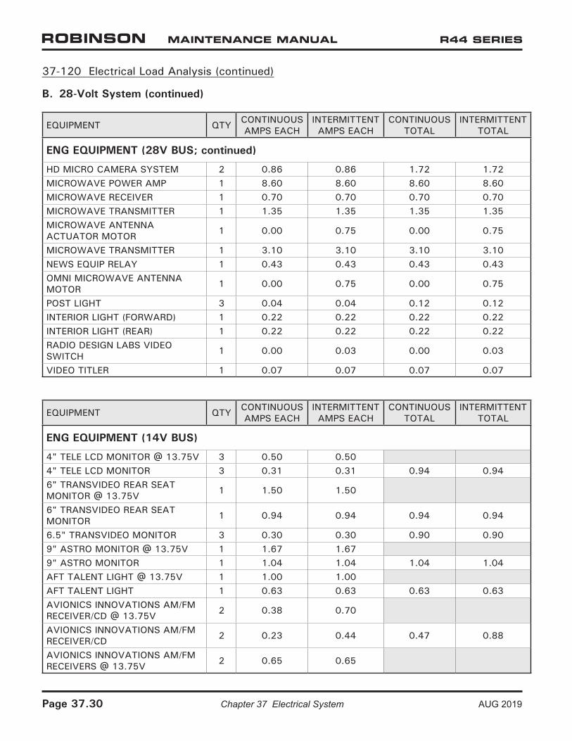
37-120 Electrical Load Analysis (continued)
B. 28-Volt System (continued)
EQUIPMENT QTY CONTINUOUS AMPS EACH
INTERMITTENT AMPS EACH
CONTINUOUS TOTAL
INTERMITTENT TOTAL
ENG EQUIPMENT (28V BUS; continued)
HD MICRO CAMERA SYSTEM 2 0.86 0.86 1.72 1.72MICROWAVE POWER AMP 1 8.60 8.60 8.60 8.60MICROWAVE RECEIVER 1 0.70 0.70 0.70 0.70MICROWAVE TRANSMITTER 1 1.35 1.35 1.35 1.35MICROWAVE ANTENNA ACTUATOR MOTOR 1 0.00 0.75 0.00 0.75
MICROWAVE TRANSMITTER 1 3.10 3.10 3.10 3.10NEWS EQUIP RELAY 1 0.43 0.43 0.43 0.43OMNI MICROWAVE ANTENNA MOTOR 1 0.00 0.75 0.00 0.75
POST LIGHT 3 0.04 0.04 0.12 0.12INTERIOR LIGHT (FORWARD) 1 0.22 0.22 0.22 0.22INTERIOR LIGHT (REAR) 1 0.22 0.22 0.22 0.22RADIO DESIGN LABS VIDEO SWITCH 1 0.00 0.03 0.00 0.03
VIDEO TITLER 1 0.07 0.07 0.07 0.07
EQUIPMENT QTY CONTINUOUS AMPS EACH
INTERMITTENT AMPS EACH
CONTINUOUS TOTAL
INTERMITTENT TOTAL
ENG EQUIPMENT (14V BUS)
4" TELE LCD MONITOR @ 13.75V 3 0.50 0.504" TELE LCD MONITOR 3 0.31 0.31 0.94 0.946" TRANSVIDEO REAR SEAT MONITOR @ 13.75V 1 1.50 1.50
6" TRANSVIDEO REAR SEAT MONITOR 1 0.94 0.94 0.94 0.94
6.5" TRANSVIDEO MONITOR 3 0.30 0.30 0.90 0.909" ASTRO MONITOR @ 13.75V 1 1.67 1.679" ASTRO MONITOR 1 1.04 1.04 1.04 1.04AFT TALENT LIGHT @ 13.75V 1 1.00 1.00AFT TALENT LIGHT 1 0.63 0.63 0.63 0.63AVIONICS INNOVATIONS AM/FM RECEIVER/CD @ 13.75V 2 0.38 0.70
AVIONICS INNOVATIONS AM/FM RECEIVER/CD 2 0.23 0.44 0.47 0.88
AVIONICS INNOVATIONS AM/FM RECEIVERS @ 13.75V 2 0.65 0.65
Page 37.30 Chapter 37 Electrical System AUG 2019
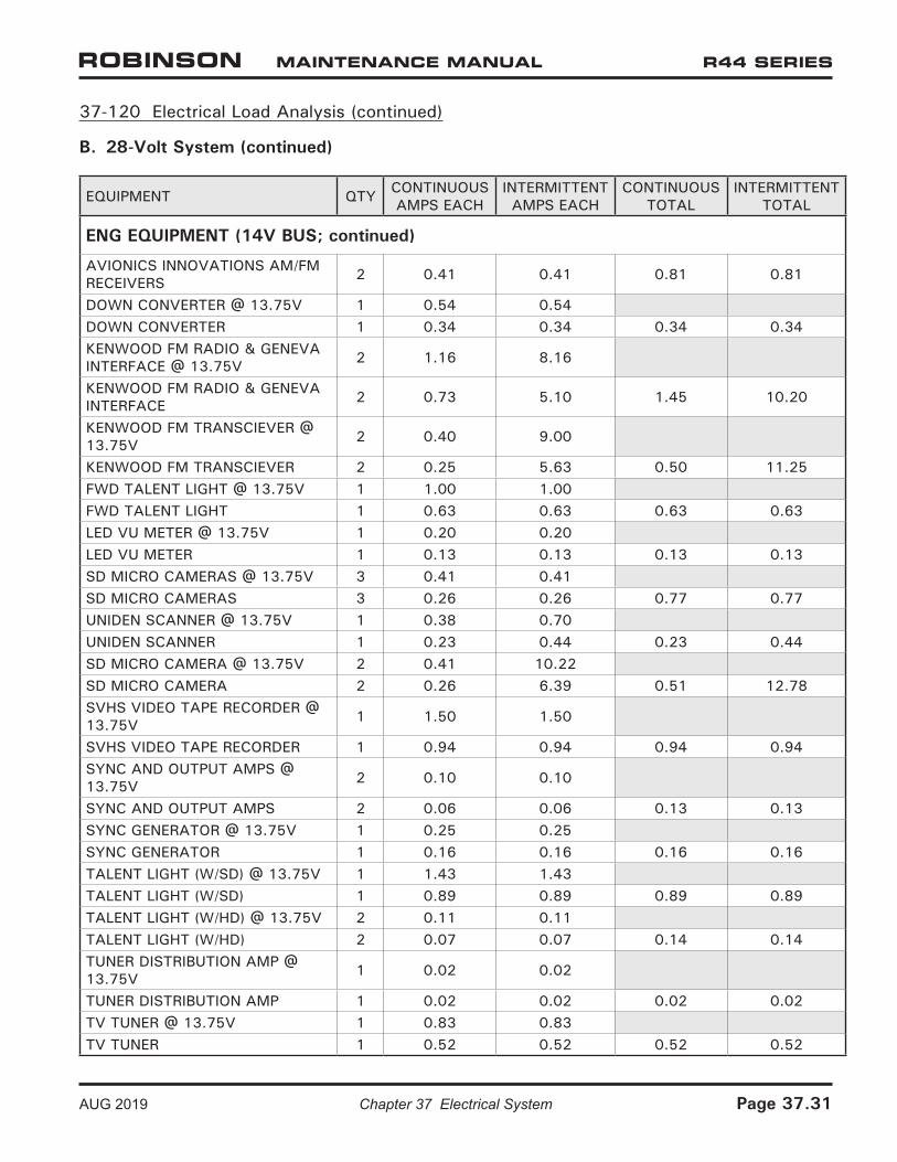
37-120 Electrical Load Analysis (continued)
B. 28-Volt System (continued)
EQUIPMENT QTY CONTINUOUS AMPS EACH
INTERMITTENT AMPS EACH
CONTINUOUS TOTAL
INTERMITTENT TOTAL
ENG EQUIPMENT (14V BUS; continued)
AVIONICS INNOVATIONS AM/FM RECEIVERS 2 0.41 0.41 0.81 0.81
DOWN CONVERTER @ 13.75V 1 0.54 0.54DOWN CONVERTER 1 0.34 0.34 0.34 0.34KENWOOD FM RADIO & GENEVA INTERFACE @ 13.75V 2 1.16 8.16
KENWOOD FM RADIO & GENEVA INTERFACE 2 0.73 5.10 1.45 10.20
KENWOOD FM TRANSCIEVER @ 13.75V 2 0.40 9.00
KENWOOD FM TRANSCIEVER 2 0.25 5.63 0.50 11.25FWD TALENT LIGHT @ 13.75V 1 1.00 1.00FWD TALENT LIGHT 1 0.63 0.63 0.63 0.63LED VU METER @ 13.75V 1 0.20 0.20LED VU METER 1 0.13 0.13 0.13 0.13SD MICRO CAMERAS @ 13.75V 3 0.41 0.41SD MICRO CAMERAS 3 0.26 0.26 0.77 0.77UNIDEN SCANNER @ 13.75V 1 0.38 0.70UNIDEN SCANNER 1 0.23 0.44 0.23 0.44SD MICRO CAMERA @ 13.75V 2 0.41 10.22SD MICRO CAMERA 2 0.26 6.39 0.51 12.78SVHS VIDEO TAPE RECORDER @ 13.75V 1 1.50 1.50
SVHS VIDEO TAPE RECORDER 1 0.94 0.94 0.94 0.94SYNC AND OUTPUT AMPS @ 13.75V 2 0.10 0.10
SYNC AND OUTPUT AMPS 2 0.06 0.06 0.13 0.13SYNC GENERATOR @ 13.75V 1 0.25 0.25SYNC GENERATOR 1 0.16 0.16 0.16 0.16TALENT LIGHT (W/SD) @ 13.75V 1 1.43 1.43TALENT LIGHT (W/SD) 1 0.89 0.89 0.89 0.89TALENT LIGHT (W/HD) @ 13.75V 2 0.11 0.11TALENT LIGHT (W/HD) 2 0.07 0.07 0.14 0.14TUNER DISTRIBUTION AMP @ 13.75V 1 0.02 0.02
TUNER DISTRIBUTION AMP 1 0.02 0.02 0.02 0.02TV TUNER @ 13.75V 1 0.83 0.83TV TUNER 1 0.52 0.52 0.52 0.52
AUG 2019 Chapter 37 Electrical System Page 37.31
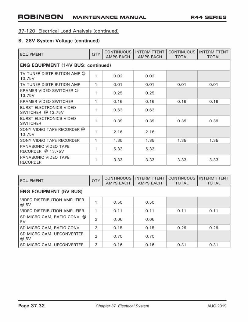
37-120 Electrical Load Analysis (continued)
B. 28V System Voltage (continued)
EQUIPMENT QTY CONTINUOUS AMPS EACH
INTERMITTENT AMPS EACH
CONTINUOUS TOTAL
INTERMITTENT TOTAL
ENG EQUIPMENT (14V BUS; continued)
TV TUNER DISTRIBUTION AMP @ 13.75V 1 0.02 0.02
TV TUNER DISTRIBUTION AMP 1 0.01 0.01 0.01 0.01KRAMER VIDEO SWITCHER @ 13.75V 1 0.25 0.25
KRAMER VIDEO SWITCHER 1 0.16 0.16 0.16 0.16BURST ELECTRONICS VIDEO SWITCHER @ 13.75V 1 0.63 0.63
BURST ELECTRONICS VIDEO SWITCHER 1 0.39 0.39 0.39 0.39
SONY VIDEO TAPE RECORDER @ 13.75V 1 2.16 2.16
SONY VIDEO TAPE RECORDER 1 1.35 1.35 1.35 1.35PANASONIC VIDEO TAPE RECORDER @ 13.75V 1 5.33 5.33
PANASONIC VIDEO TAPE RECORDER 1 3.33 3.33 3.33 3.33
EQUIPMENT QTY CONTINUOUS AMPS EACH
INTERMITTENT AMPS EACH
CONTINUOUS TOTAL
INTERMITTENT TOTAL
ENG EQUIPMENT (5V BUS)
VIDEO DISTRIBUTION AMPLIFIER @ 5V 1 0.50 0.50
VIDEO DISTRIBUTION AMPLIFIER 1 0.11 0.11 0.11 0.11SD MICRO CAM, RATIO CONV. @ 5V 2 0.66 0.66
SD MICRO CAM, RATIO CONV. 2 0.15 0.15 0.29 0.29SD MICRO CAM. UPCONVERTER @ 5V 2 0.70 0.70
SD MICRO CAM. UPCONVERTER 2 0.16 0.16 0.31 0.31
Page 37.32 Chapter 37 Electrical System AUG 2019