Embed Size (px)
Citation preview

Chapter 33
Electromagnetic Waves Today’s information age is based almost entirely on the physics of electromagnetic waves. The connection between electric and magnetic fields to produce light is one of the greatest achievements produced by physics, and electromagnetic waves are at the core of many fields in science and engineering.
In this chapter we introduce fundamental concepts and explore the properties of electromagnetic waves and optics, the study of visible light, which is a branch of electromagnetism.
(33-1)

Fig. 33-1
The wavelength/frequency range in which electromagnetic (EM) waves are visible (light) is only a tiny fraction of the entire electromagnetic spectrum.
33.1 Maxwell’s Rainbow
Fig. 33-2
(33-2)

An LC oscillator causes currents to flow sinusoidally, which in turn produces oscillating electric and magnetic fields, which then propagate through space as EM waves.
Fig. 33-3
Oscillation Frequency:
1
LC
Next slide
33.3 The Traveling Electromagnetic Wave, Qualitatively
(33-3)

EM fields at P looking back toward LC oscillator
Fig. 33-4
The Traveling Electromagnetic (EM) Wave, Qualitatively
1. Electric and magnetic fields are always
perpendicular to direction in which wave
is traveling transverse wave (Ch. 16).
2. is always perpendicular to .
3. always gives direc
E B
E B
E B
tion of wave travel.
4. and vary sinusoidally (in time and space)
and are with each other.
E B
in phase
(33-4)

Fig. 33-5
Mathematical Description of Traveling EM Waves
Electric Field: sinmE E kx t
Magnetic Field: sinmB B kx t
Wave Speed:0 0
1c
Wavenumber:2
k
Angular frequency:2
Vacuum Permittivity: 0
Vacuum Permeability: 0
All EM waves travel a c in vacuum
Amplitude Ratio: m
m
Ec
B Magnitude Ratio:
E t
cB t
EM Wave Simulation
(33-5)

• Unlike all the waves discussed in Chs. 16 and 17, EM waves require no medium through/along which to travel. EM waves can travel through empty space (vacuum)!
• Speed of light is independent of speed of observer! You could be heading toward a light beam at the speed of light, but you would still measure c as the speed of the beam!
A Most Curious Wave
299 792 458 m/sc
(33-6)

Changing magnetic fields produce electric fields, Faraday’s law of induction:
Fig. 33-6
3.4 The Traveling EM Wave, Quantitatively
Induced Electric Field
cos and cosm m
E BkE kx t B kx t
x t
BdE d s
dt
E ds E dE h Eh h dE
B B h dx
dB dE dB
h dE h dxdt dx dt
E B
x t
cos cos mm m
m
EkE kx t B kx t c
B (33-7)
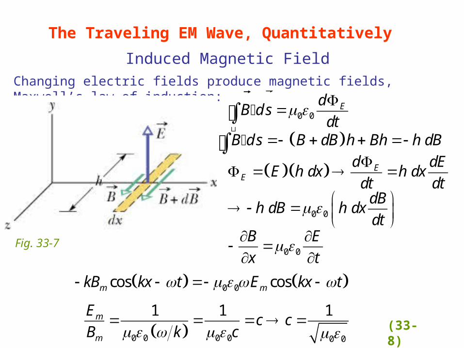
Changing electric fields produce magnetic fields, Maxwell’s law of induction:
The Traveling EM Wave, Quantitatively
Induced Magnetic Field
0 0Ed
B d sdt
B ds B dB h Bh h dB ����������������������������
E
E
d dEE h dx h dx
dt dt
0 0 dB
h dB h dxdt
0 0
B E
x t
0 0cos cosm mkB kx t E kx t
Fig. 33-7
0 0 0 0 0 0
1 1 1m
m
Ec c
B k c (33-8)

33.5 Energy Transport and the Poynting Vector
EM waves carry energy. The rate of energy transport in an EM wave
is characterized by the Poynting vector, :S
Poynting Vector:0
1S E B
inst inst
energy/time power
area areaS
The magnitude of S is related to the rate at which energy is transported by a wave across a unit area at any instant (inst). The unit for S is (W/m2).
The direction of at any point gives the wave's travel direction
and the direction of energy transport at that point.
S
(33-9)
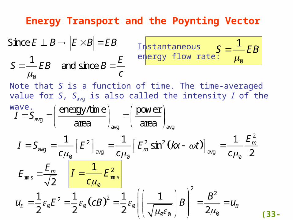
Energy Transport and the Poynting Vector
Instantaneous energy flow rate:
0
1S EB
Note that S is a function of time. The time-averaged value for S, Savg is also called the intensity I of the wave.
0
Since
1 and since
E B E B EB
ES EB B
c
avgavg avg
energy/time power
area areaI S
2
2 2 2avg avg avg
0 0 0
1 1 1sin
2m
m
EI S E E kx t
c c c
rms2mEE
2
222
0 0 000 0
1 1 1 1
2 2 2 2E B
Bu E cB B u
2rms
0
1I Ec
(33-10)

Variation of Intensity with Distance
Fig. 33-8
2
power
area 4SPIr
Consider a point source S that is emitting EM waves isotropically (equally in all directions) at a rate PS. Assume that the energy of waves is conserved as they spread from source.
How does the intensity (power/area) change with distance r?
(33-11)

(total absorption)
2 (total reflection back along path)
Radiation Pressurer
U IA t
IAF
cIA
FcF
pA
EM waves have linear momentum as well as energylight can exert pressure.
33.6 Radiation Pressure
incidentS
p
incidentS
reflectedS
p
Total absorption:U
pc
Total reflectionback along path:
2 Up
c
pF
t
power energy/time
area area
I
U t
A
2 r
Ip
c
r
Ip
c
(33-12)

The polarization of light describes how the electric field in the EM wave oscillates.
Vertically planepolarized (or linearly polarized)
33.7 Polarization
Fig. 33-10 (33-13)
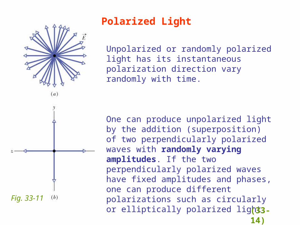
Unpolarized or randomly polarized light has its instantaneous polarization direction vary randomly with time.
Polarized Light
Fig. 33-11
One can produce unpolarized light by the addition (superposition) of two perpendicularly polarized waves with randomly varying amplitudes. If the two perpendicularly polarized waves have fixed amplitudes and phases, one can produce different polarizations such as circularly or elliptically polarized light.
(33-14)

Polarizing Sheet
Fig. 33-12
Only the electric field component along the polarizing direction of polarizing sheet is passed (transmitted); the perpendicular component is blocked (absorbed).
I0
I
(33-15)

Intensity of Transmitted Polarized Light
Fig. 33-13
Intensity of transmitted light,unpolarized incident light:
0
1
2I I
Since only the component of the incident electric field E parallel to the polarizing axis is transmitted.
transmitted cosyE E E
Intensity of transmitted light,polarized incident light:
20 cosI I
2 20 0 0avg avg
1cos cos
2I I I I
For unpolarized light, varies randomly in time:
(33-16)
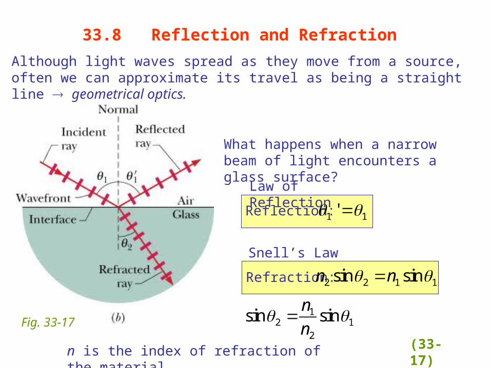
Although light waves spread as they move from a source, often we can approximate its travel as being a straight line geometrical optics.
33.8 Reflection and Refraction
Fig. 33-17
What happens when a narrow beam of light encounters a glass surface?
Reflection: 1 1'
Refraction: 2 2 1 1sin sinn n
Law of Reflection
Snell’s Law
12 1
2
sin sinn
n
n is the index of refraction of the material. (33-17)

For light going from n1 to n2:
• n2 = n1 2 = 1
• n2 > n1 2<1, light bent toward normal
• n2 < n1 2 > 1, light bent away from normal
Refraction of light traveling from a medium with n1 to a medium with n2
Fig. 33-18 (33-18)

The index of refraction n encountered by light in any medium except vacuum depends on the wavelength of the light. So if light consisting of different wavelengths enters a material, the different wavelengths will be refracted differently chromatic dispersion.
Chromatic Dispersion
Fig. 33-19Fig. 33-20
N2,blue>n2,red
Chromatic dispersion can be good (e.g., used to analyze wavelength composition of light) or bad (e.g., chromatic aberration in lenses).
(33-19)

Chromatic Dispersion
Fig. 33-21
Chromatic dispersion can be good (e.g., used to analyze wavelength composition of light)
or bad (e.g., chromatic aberration in lenses)
prism
lens(33-20)

Rainbows
Fig. 33-22
Sunlight consists of all visible colors and water is dispersive, so when sunlight is refracted as it enters water droplets, is reflected off the back surface, and again is refracted as it exits the water drops, the range of angles for the exiting ray will depend on the color of the ray. Since blue is refracted more strongly than red, only droplets that are closer to the rainbow center (A) will refract/reflect blue light to the observer (O). Droplets at larger angles will still refract/reflect red light to the observer.
What happens for rays that reflect twice off the back surfaces of the droplets?
(33-21)

For light that travels from a medium with a larger index of refraction to a medium with a smaller index of refraction n1>n2 2>1, as 1 increases, 2 will reach 90o (the largest possible angle for refraction) before 1 does.
33.9 Total Internal Reflection
1 2 2sin sin 90cn n n
Fig. 33-24
n1
n2
Critical Angle:1 2
1
sinc
n
n
When 1> c no light is refracted (Snell’s law does not have a solution!) so no light is transmitted Total Internal Reflection
Total internal reflection can be used, for example, to guide/contain light along an optical fiber. (33-22)

33.10 Polarization by Reflection
Fig. 33-27
Brewster’s Law
Applications1. Perfect window: since parallel polarization
is not reflected, all of it is transmitted2. Polarizer: only the perpendicular
component is reflected, so one can select only this component of the incident polarization
1 2
1 2 2
90
sin sin
sin sin 90 cos
B r
B r
B B B
n n
n n n
Brewster Angle:1 2
1
tanB
n
n In which direction does light reflecting
off a lake tend to be polarized?
When the refracted ray is perpendicular to the reflected ray, the electric field parallel to the page (plane of incidence) in the medium does not produce a reflected ray since there is no component of that field perpendicular to the reflected ray (EM waves are transverse).
(33-23)