Embed Size (px)
Citation preview
Chapter 3-1
Chapter 3 The First Law of Thermodynamics: Closed Systems
The first law of thermodynamics is an expression of the conservation ofenergy principle. Energy can cross the boundaries of a closed system inthe form of heat or work. Energy transfer across a system boundary duesolely to the temperature difference between a system and its surroundingsis called heat.
Work energy can be thought of as the energy expended to lift a weight.
Sign Convention
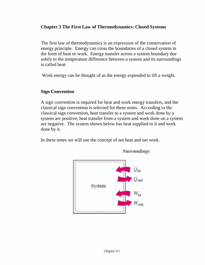
A sign convention is required for heat and work energy transfers, and theclassical sign convention is selected for these notes. According to theclassical sign convention, heat transfer to a system and work done by asystem are positive; heat transfer from a system and work done on a systemare negative. The system shown below has heat supplied to it and workdone by it.
In these notes we will use the concept of net heat and net work.
Chapter 3-2
Heat Transfer
Recall that heat is energy in transition across the system boundary solelydue to the temperature difference between the system and its surroundings.The net heat transferred to a system is defined as
Q Q Qnet in out= −∑∑Here, Qin and Qout are the magnitudes of the heat transfer values. In mostthermodynamics texts, the quantity Q is meant to be the net heattransferred to the system, Qnet. Since heat transfer is process dependent,the differential of heat transfer δQ is called inexact. We often think aboutthe heat transfer per unit mass of the system, Q.
m=
Heat transfer has the units of energy joules (we will use kilojoules, kJ) orthe units of energy per unit mass, kJ/kg.
Since heat transfer is energy in transition across the system boundary dueto a temperature difference, there are three modes of heat transfer at theboundary that depend on the temperature difference between the boundarysurface and the surroundings. These are conduction, convection, andradiation. However, when solving problems in thermodynamics involvingheat transfer to a system, the heat transfer is usually given or is calculatedby applying the first law, or the conservation of energy, to the system.
An adiabatic process is one in which the system is perfectly insulated andthe heat transfer is zero.
For those of us who do not have the opportunity to have a complete coursein heat transfer theory and applications, the following is a shortintroduction to the basic mechanisms of heat transfer. Those of us whohave a complete course in heat transfer theory may elect to omit thismaterial at this time.
Chapter 3-3
Heat transfer is energy in transition due to a temperature difference. Thethree modes of heat transfer are conduction, convection, and radiation.
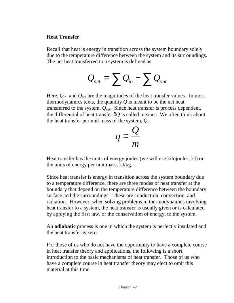
Conduction through Plane Walls
Conduction heat transfer is a progressive exchange of energy between themolecules of a substance.
Fourier's law of heat conduction is
!Q A kdT
dxcond t= −here
!Qcond = heat flow per unit time (W)kt = thermal conductivity (W/m⋅K)A = area normal to heat flow (m2)dT
dx= temperature gradient in the direction of heat flow (°C/m)
Chapter 3-4
Integrating Fourier's law
!Q kAT
xcond = ∆∆
Since T2>T1, the heat flows from right to left in the above figure.
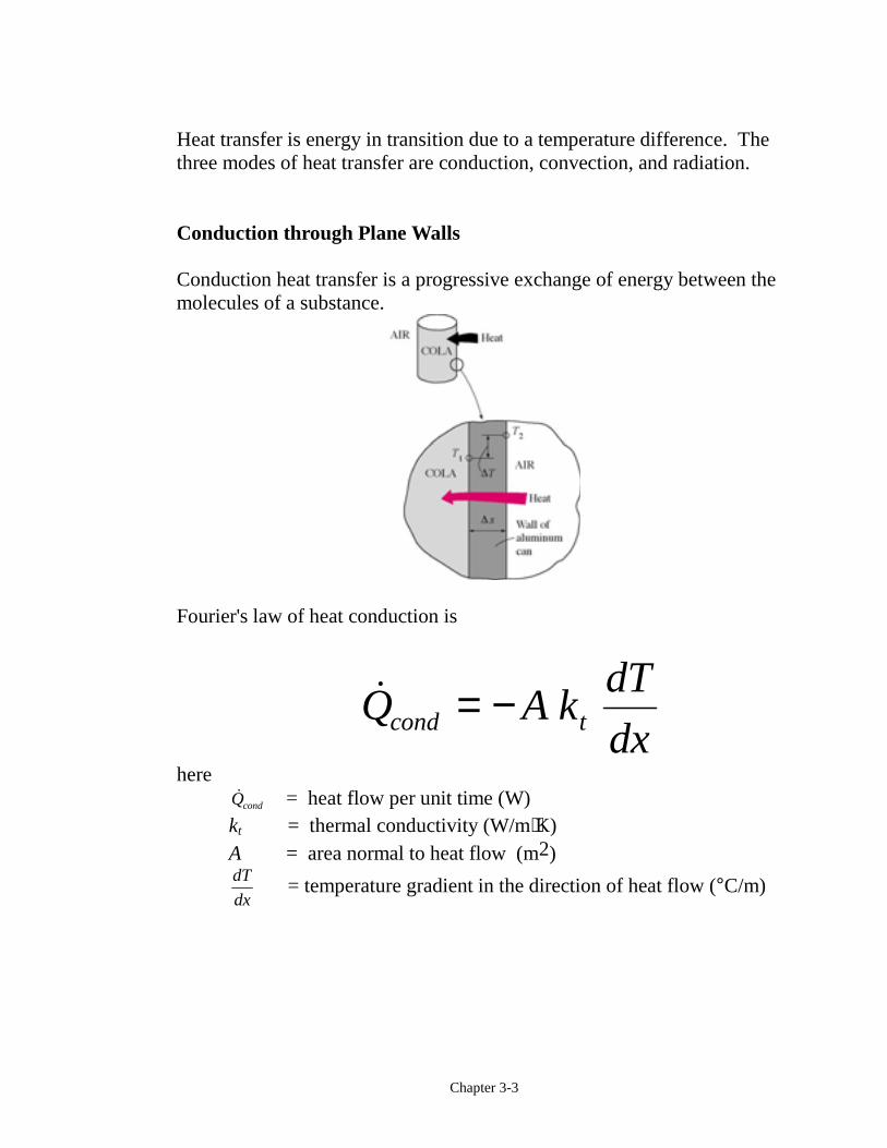
Example 3-1
A flat wall is composed of 20 cm of brick (kt = 0.72 W/m⋅K, seeTable 3-1). The right face temperature of the brick is 900°C, and the leftface temperature of the brick is 20°C. Determine the rate of heatconduction through the wall per unit area of wall.
Tright = 900°C
Tleft = 20°C
20 cm
Chapter 3-5
!
!.
( )
.
Q k AT
x
Q
Ak
T
x
W
m K
K
m
W
m
cond t
condt
=
= =⋅
−FHG
IKJ
=
∆∆
∆∆
0 72900 20
0 2
31682
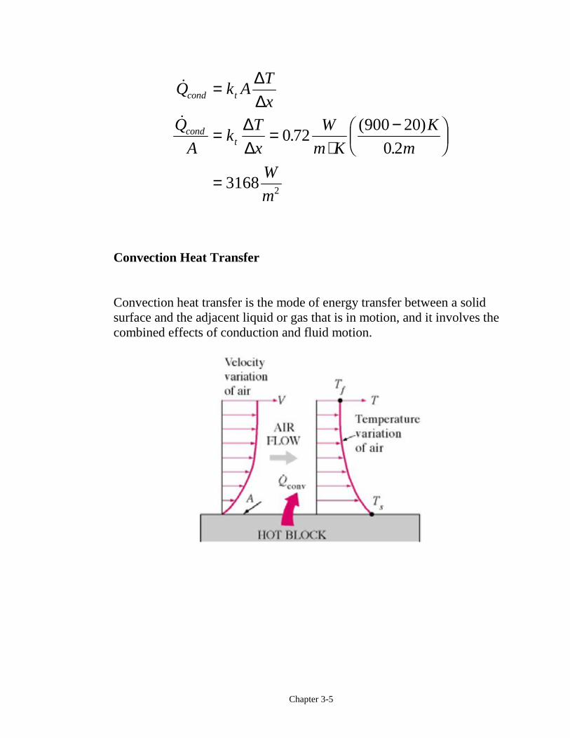
Convection Heat Transfer
Convection heat transfer is the mode of energy transfer between a solidsurface and the adjacent liquid or gas that is in motion, and it involves thecombined effects of conduction and fluid motion.
Chapter 3-6
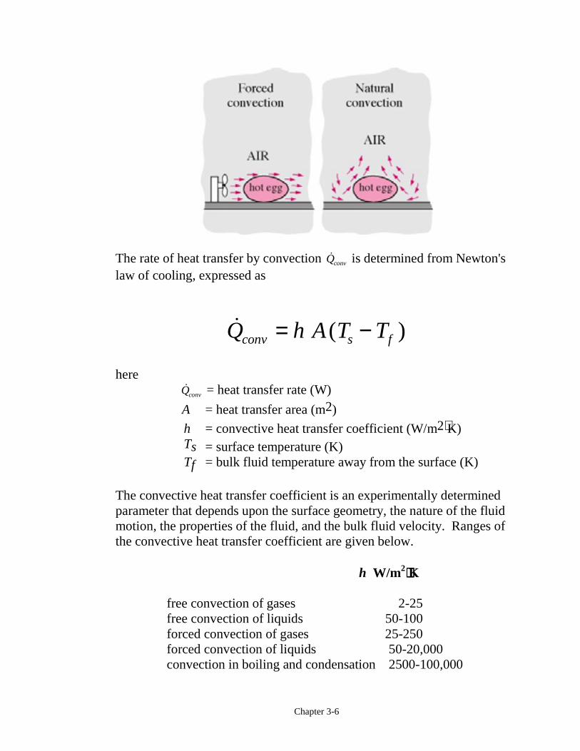
The rate of heat transfer by convection !Qconv is determined from Newton'slaw of cooling, expressed as
! ( )Q h A T Tconv s f= −
here !Qconv = heat transfer rate (W)
A = heat transfer area (m2)
h = convective heat transfer coefficient (W/m2⋅K) Ts = surface temperature (K)
Tf = bulk fluid temperature away from the surface (K)
The convective heat transfer coefficient is an experimentally determinedparameter that depends upon the surface geometry, the nature of the fluidmotion, the properties of the fluid, and the bulk fluid velocity. Ranges ofthe convective heat transfer coefficient are given below.
h W/m2⋅⋅⋅⋅K
free convection of gases 2-25free convection of liquids 50-100forced convection of gases 25-250forced convection of liquids 50-20,000convection in boiling and condensation 2500-100,000
Chapter 3-7
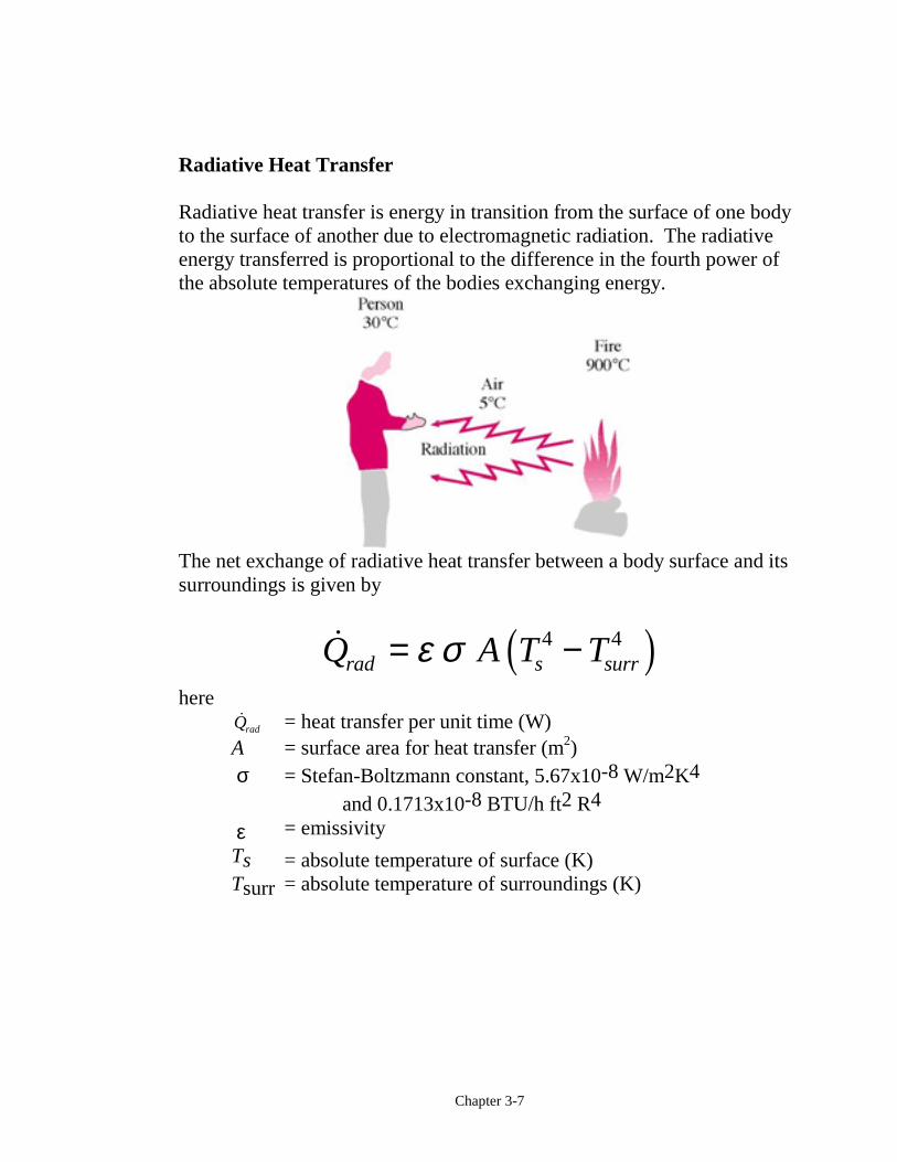
Radiative Heat Transfer
Radiative heat transfer is energy in transition from the surface of one bodyto the surface of another due to electromagnetic radiation. The radiativeenergy transferred is proportional to the difference in the fourth power ofthe absolute temperatures of the bodies exchanging energy.
The net exchange of radiative heat transfer between a body surface and itssurroundings is given by
!Q A T Trad s surr= −ε σ 4 4c hhere
!Qrad = heat transfer per unit time (W)A = surface area for heat transfer (m2) σ = Stefan-Boltzmann constant, 5.67x10⁻⁸ W/m2K4
and 0.1713x10⁻⁸ BTU/h ft2 R4 ε = emissivity
Ts = absolute temperature of surface (K)Tsurr = absolute temperature of surroundings (K)
Chapter 3-8
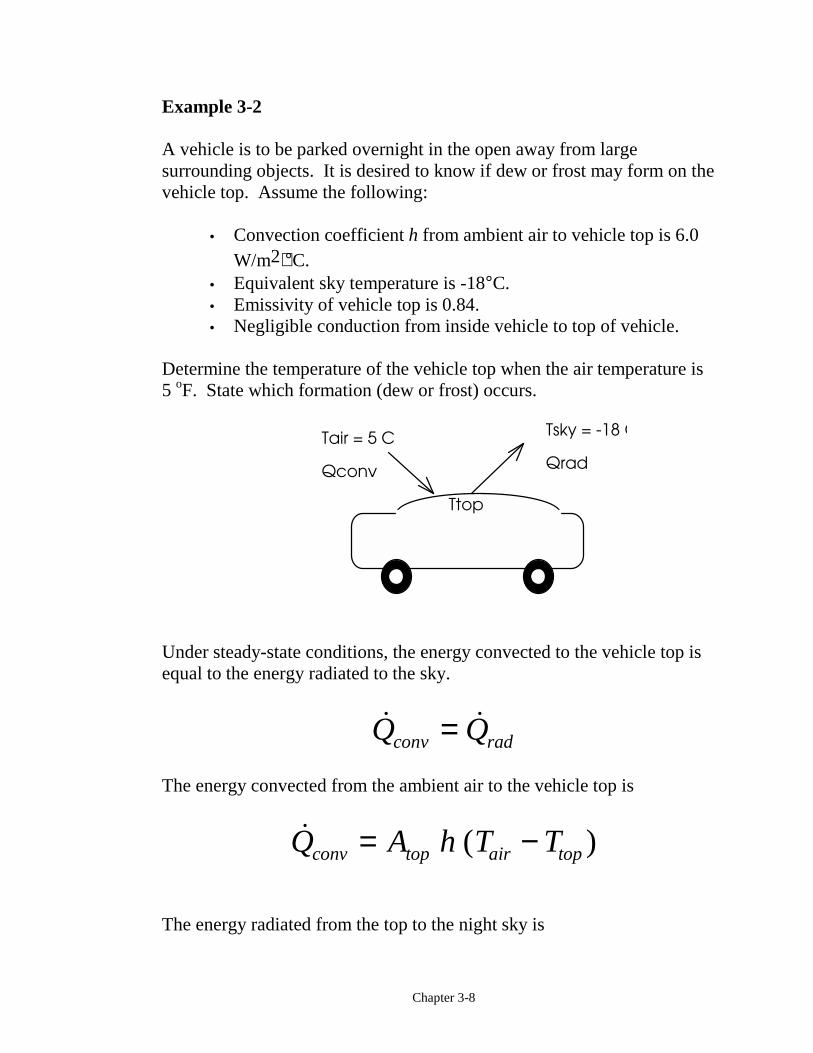
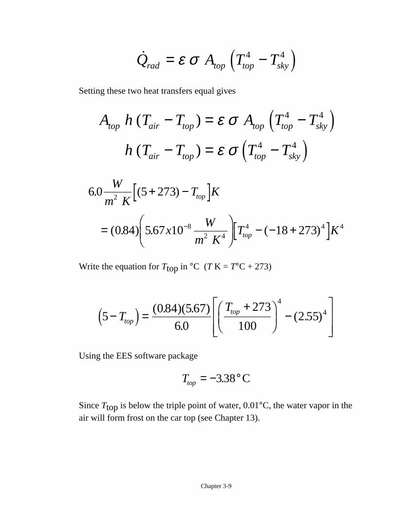
Example 3-2
A vehicle is to be parked overnight in the open away from largesurrounding objects. It is desired to know if dew or frost may form on thevehicle top. Assume the following:
• Convection coefficient h from ambient air to vehicle top is 6.0W/m2⋅°C.
• Equivalent sky temperature is -18°C.• Emissivity of vehicle top is 0.84.• Negligible conduction from inside vehicle to top of vehicle.
Determine the temperature of the vehicle top when the air temperature is5 oF. State which formation (dew or frost) occurs.
Ttop
Tsky = -18 CTair = 5 C
Qconv Qrad
Under steady-state conditions, the energy convected to the vehicle top isequal to the energy radiated to the sky.
! !Q Qconv rad=The energy convected from the ambient air to the vehicle top is
! ( )Q A h T Tconv top air top= −
The energy radiated from the top to the night sky is
Chapter 3-9
!Q A T Trad top top sky= −ε σ 4 4d iSetting these two heat transfers equal gives
A h T T A T T
h T T T T
top air top top top sky
air top top sky
( )
( )
− = −
− = −
ε σ
ε σ
4 4
4 4
d id i
6 0 273
0 84 5 67 10 18 273
2
82 4
4 4 4
. (5 )
( . ) . ( )
W
m KT K
xW
m KT K
top
top
+ −
=FHG
IKJ − − +−
Write the equation for Ttop in °C (T K = T°C + 273)
5084 67
6 0
273
1002 55
4
4− =+F
HGIKJ −
LNMM
OQPPT
Ttop
topd i ( . )(5. )
.( . )
Using the EES software package
Ttop = − °3 38. C
Since Ttop is below the triple point of water, 0.01°C, the water vapor in theair will form frost on the car top (see Chapter 13).
Chapter 3-10
Extra Problem
Explore what happens to Ttop as you vary the convective heat transfercoefficient. On a night when the atmosphere is particularly still and coldand has a clear sky, why do fruit growers use fans to increase the airvelocity in their fruit groves?
Work
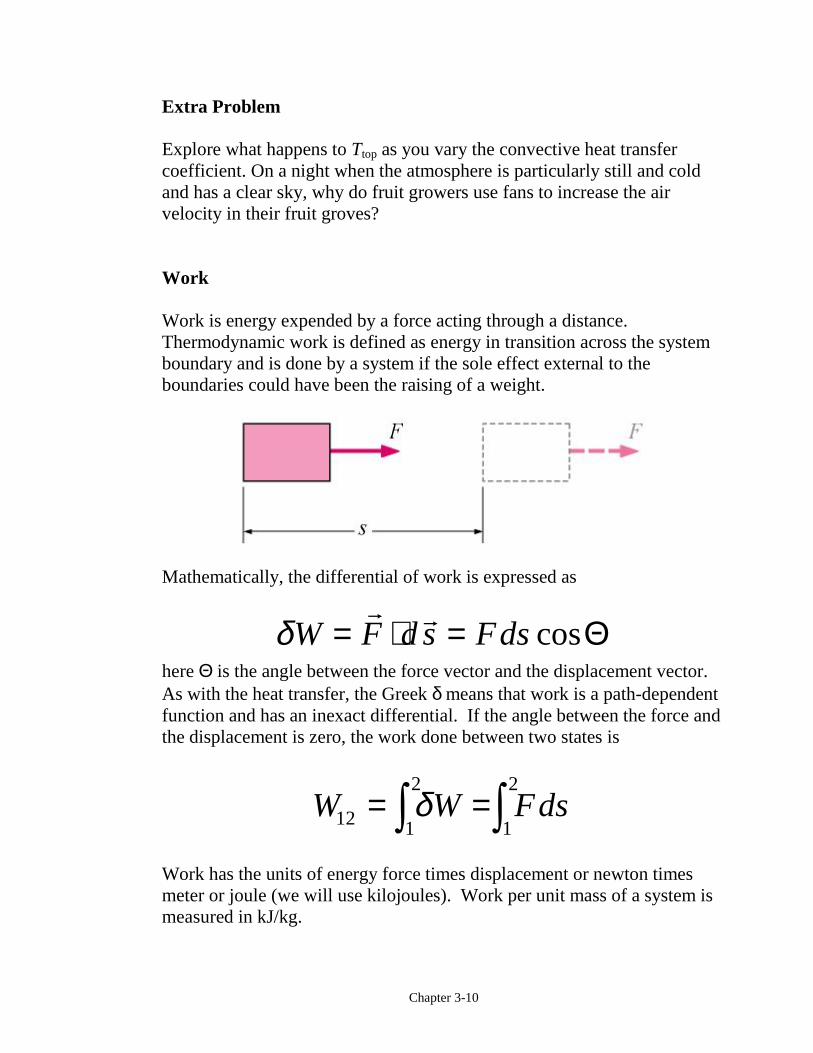
Work is energy expended by a force acting through a distance.Thermodynamic work is defined as energy in transition across the systemboundary and is done by a system if the sole effect external to theboundaries could have been the raising of a weight.
Mathematically, the differential of work is expressed as
δW F d s Fds= ⋅ =" "
cosΘhere Θ is the angle between the force vector and the displacement vector.As with the heat transfer, the Greek δ means that work is a path-dependentfunction and has an inexact differential. If the angle between the force andthe displacement is zero, the work done between two states is
W W Fds12 1
2
1
2= =z zδ
Work has the units of energy force times displacement or newton timesmeter or joule (we will use kilojoules). Work per unit mass of a system ismeasured in kJ/kg.
Chapter 3-11
Common Types of Work Energy
The net work done by the system may be in two forms. First, there can bework crossing the system boundary in the form of a rotating shaft orelectrical work. We will call shaft work and electrical work “other” work,that is, work not associated with a moving boundary. In thermodynamicselectrical energy is normally considered to be work energy rather than heatenergy, but the placement of the system boundary dictates whether toinclude electrical energy as work or heat. Second, the system may do workon its surroundings because of moving boundaries.
The net work done by a closed system is defined by
W W W Wnet out in other b= − +∑ ∑d iHere, Wout and Win are the magnitudes of the other work forms crossing theboundary. Wb is the work due to the moving boundary and will be positiveor negative depending upon the process.
Or
W W Wnet netother
b= +e jSeveral types of “other” work (shaft work, electrical work, etc.) arediscussed in the text.
Boundary Work
Work is energy expended when a force acts through a displacement.Boundary work occurs because the mass of the substance contained withinthe system boundary causes a force, the pressure times the surface area, to
Chapter 3-12
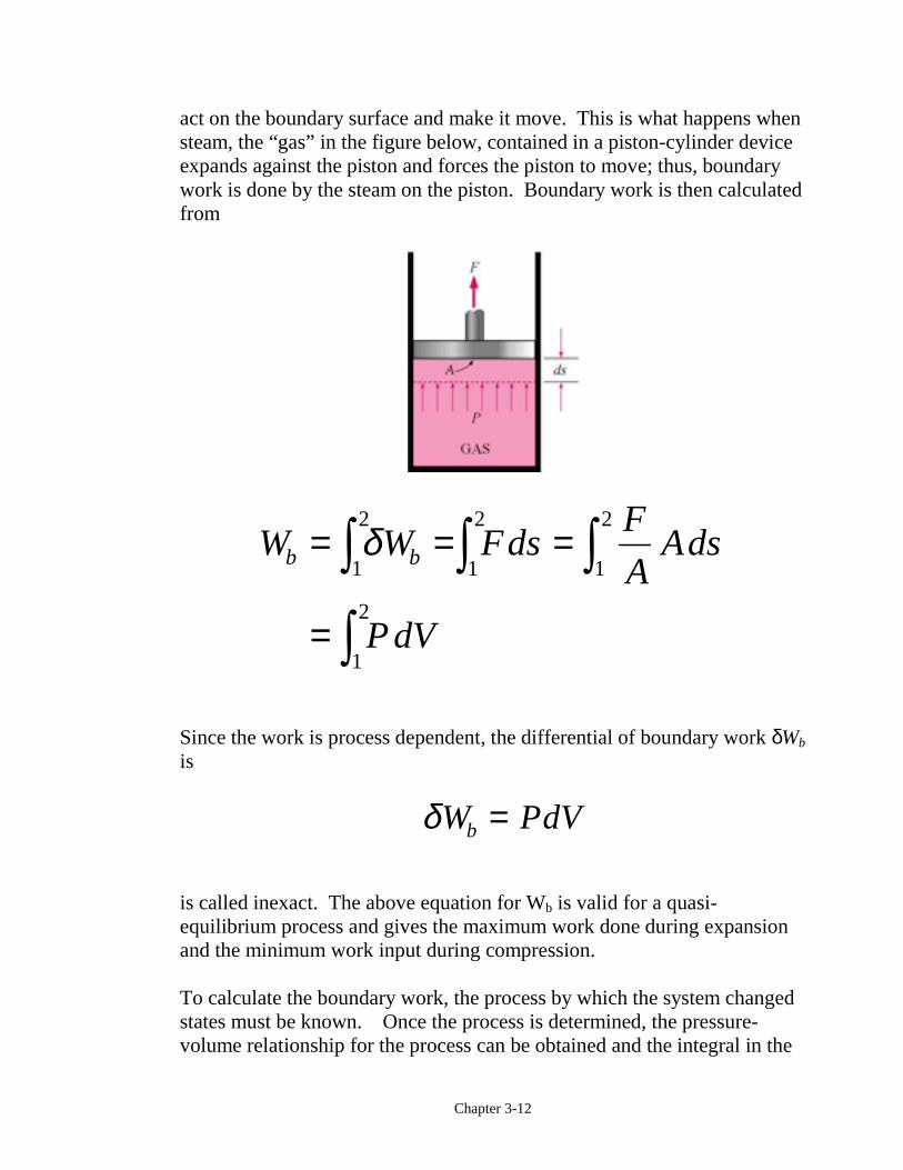
act on the boundary surface and make it move. This is what happens whensteam, the “gas” in the figure below, contained in a piston-cylinder deviceexpands against the piston and forces the piston to move; thus, boundarywork is done by the steam on the piston. Boundary work is then calculatedfrom
W W FdsF
AAds
P dV
b b= = =
=
z z zzδ
1
2
1
2
1
2
1
2
Since the work is process dependent, the differential of boundary work δWb
is
δW PdVb =
is called inexact. The above equation for Wb is valid for a quasi-equilibrium process and gives the maximum work done during expansionand the minimum work input during compression.
To calculate the boundary work, the process by which the system changedstates must be known. Once the process is determined, the pressure-volume relationship for the process can be obtained and the integral in the
Chapter 3-13
boundary work equation can be performed. For each process we need todetermine
P f V= ( )
So as we work problems, we will be asking, “What is the pressure-volumerelationship for the process?” Remember that this relation is really theforce-displacement function.
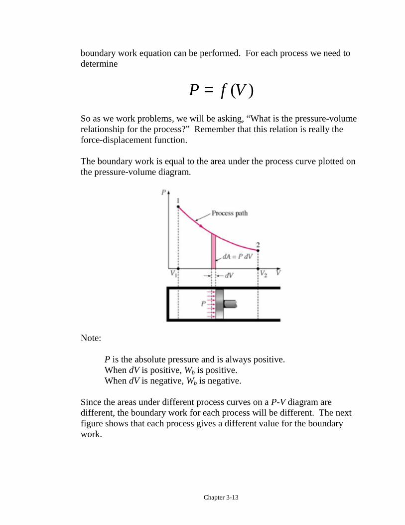
The boundary work is equal to the area under the process curve plotted onthe pressure-volume diagram.
Note:
P is the absolute pressure and is always positive.When dV is positive, Wb is positive.When dV is negative, Wb is negative.
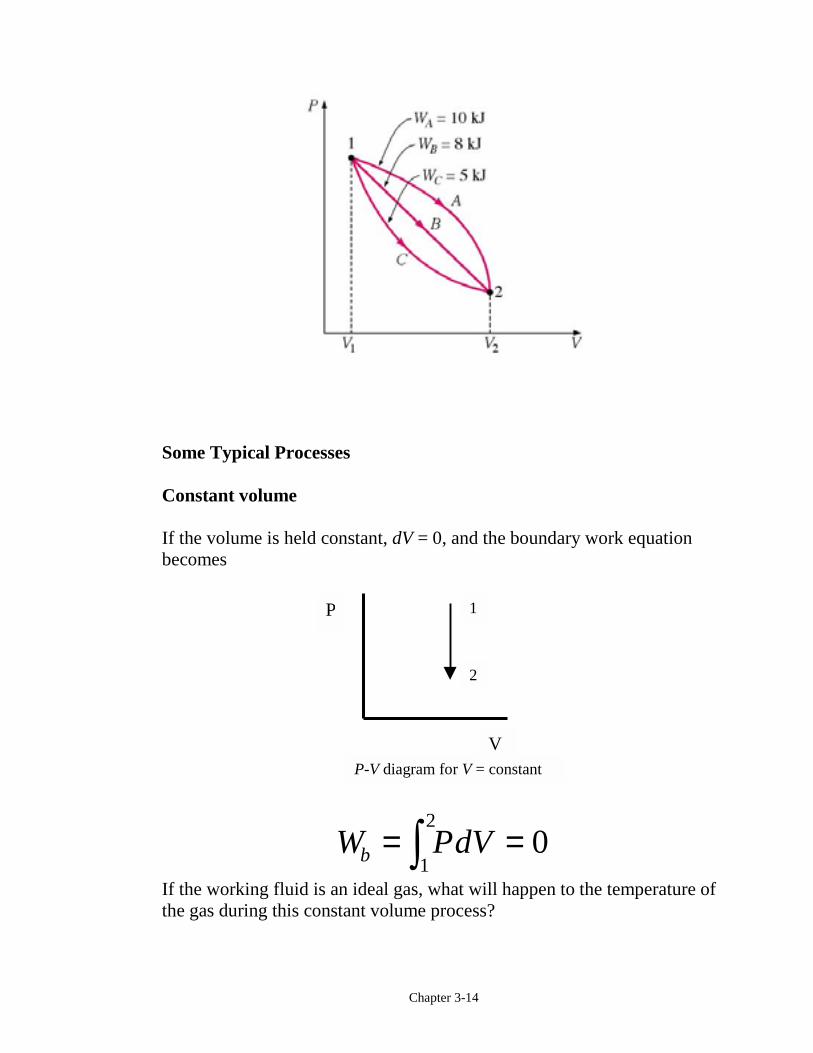
Since the areas under different process curves on a P-V diagram aredifferent, the boundary work for each process will be different. The nextfigure shows that each process gives a different value for the boundarywork.
Chapter 3-14
Some Typical Processes
Constant volume
If the volume is held constant, dV = 0, and the boundary work equationbecomes
W PdVb = =z12 0If the working fluid is an ideal gas, what will happen to the temperature ofthe gas during this constant volume process?
P
V
1
2
P-V diagram for V = constant
Chapter 3-15
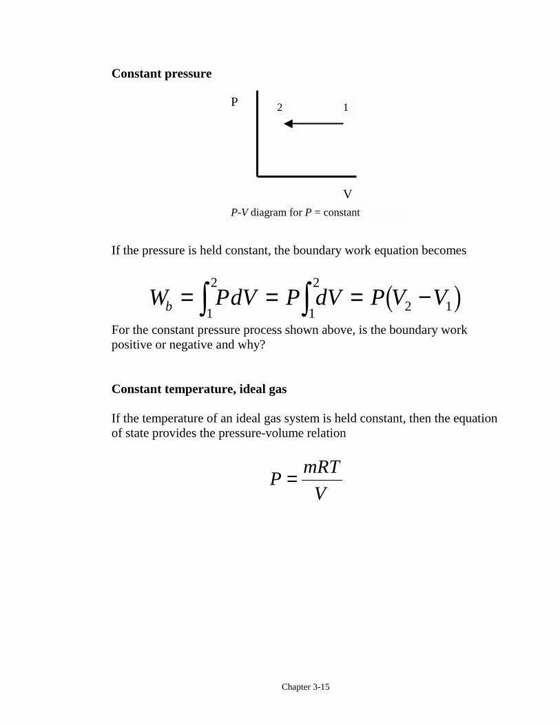
Constant pressure
If the pressure is held constant, the boundary work equation becomes
W PdV P dV P V Vb = = = −z z1
2
1
2
2 1b gFor the constant pressure process shown above, is the boundary workpositive or negative and why?
Constant temperature, ideal gas
If the temperature of an ideal gas system is held constant, then the equationof state provides the pressure-volume relation
PmRT
V=
P
V
2 1
P-V diagram for P = constant
Chapter 3-16
Then, the boundary work is
W PdVmRT
VdV
mRTV
V
b = =
=FHGIKJ
z z1
2
1
2
2
1
ln
Note: The above equation is the result of applying the ideal gas assumptionfor the equation of state. For real gases undergoing an isothermal (constanttemperature) process, the integral in the boundary work equation would bedone numerically.
The polytropic process
The polytropic process is one in which the pressure-volume relation isgiven as
PV n = constantThe exponent n may have any value from minus infinity to plus infinitydepending on the process. Some of the more common values are givenbelow.
Process Exponent nConstant pressure 0Constant volume ∞Isothermal & ideal gas 1Adiabatic & ideal gas k = CP/CV
Chapter 3-17
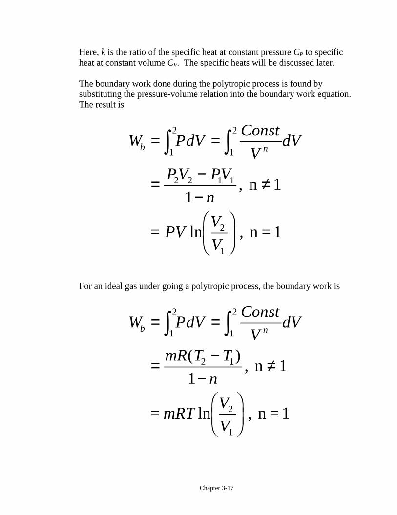
Here, k is the ratio of the specific heat at constant pressure CP to specificheat at constant volume CV. The specific heats will be discussed later.
The boundary work done during the polytropic process is found bysubstituting the pressure-volume relation into the boundary work equation.The result is
W PdVConst
VdV
PV PV
n
PVV
V
b n= =
= −−
≠
FHGIKJ
z z1
2
1
2
2 2 1 1
2
1
1,
ln ,
n 1
= n = 1
For an ideal gas under going a polytropic process, the boundary work is
W PdVConst
VdV
mR T T
n
mRTV
V
b n= =
= −−
≠
FHGIKJ
z z1
2
1
2
2 1
2
1
1
( ),
ln ,
n 1
= n = 1
Chapter 3-18
Notice that the results we obtained for an ideal gas undergoing a polytropicprocess when n = 1 are identical to those for an ideal gas undergoing theisothermal process.
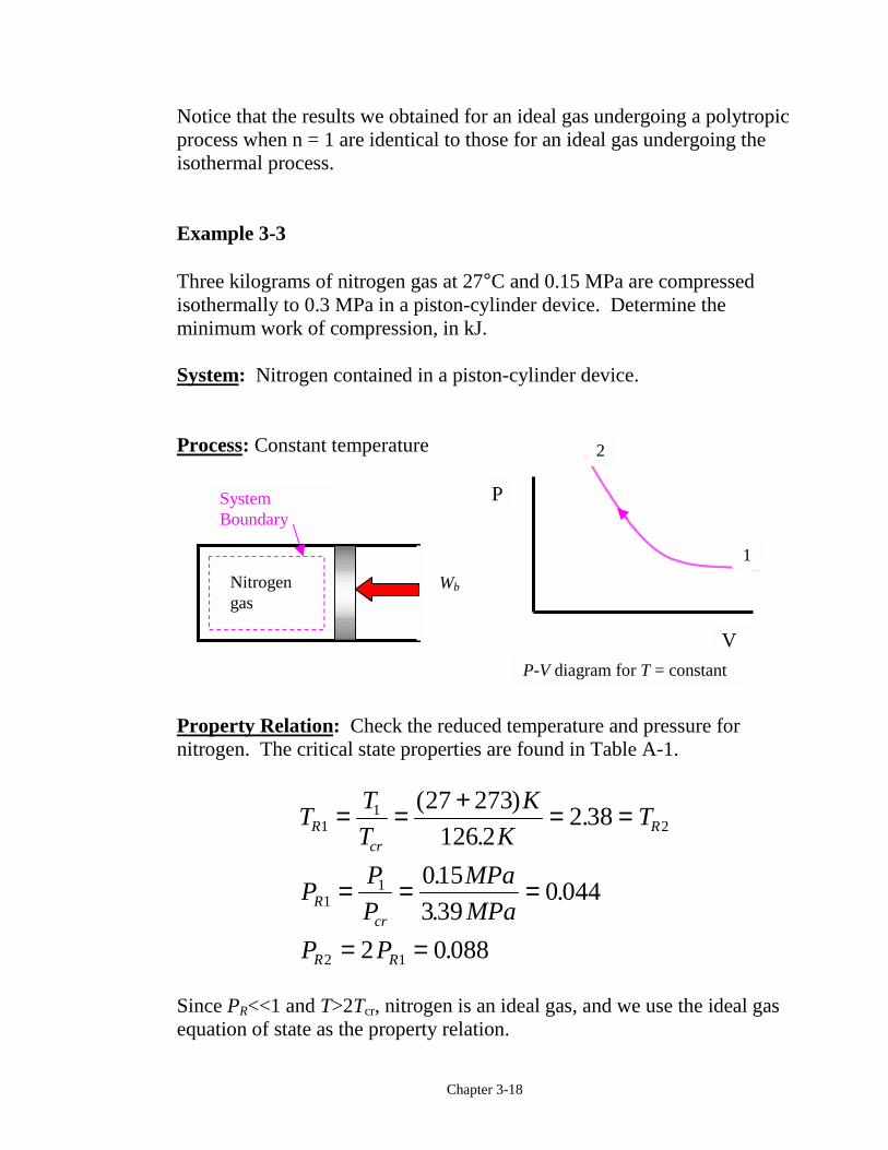
Example 3-3
Three kilograms of nitrogen gas at 27°C and 0.15 MPa are compressedisothermally to 0.3 MPa in a piston-cylinder device. Determine theminimum work of compression, in kJ.
System: Nitrogen contained in a piston-cylinder device.
Process: Constant temperature
Property Relation: Check the reduced temperature and pressure fornitrogen. The critical state properties are found in Table A-1.
TT
T
K
KT
PP
P
MPa
MPa
P P
Rcr
R
Rcr
R R
11
2
11
2 1
27 273
126 22 38
015
3 390 044
2 0 088
= = + = =
= = =
= =
( )
..
.
..
.
Since PR<<1 and T>2Tcr, nitrogen is an ideal gas, and we use the ideal gasequation of state as the property relation.
P-V diagram for T = constant
P
V
2
1
WbNitrogengas
SystemBoundary
Chapter 3-19
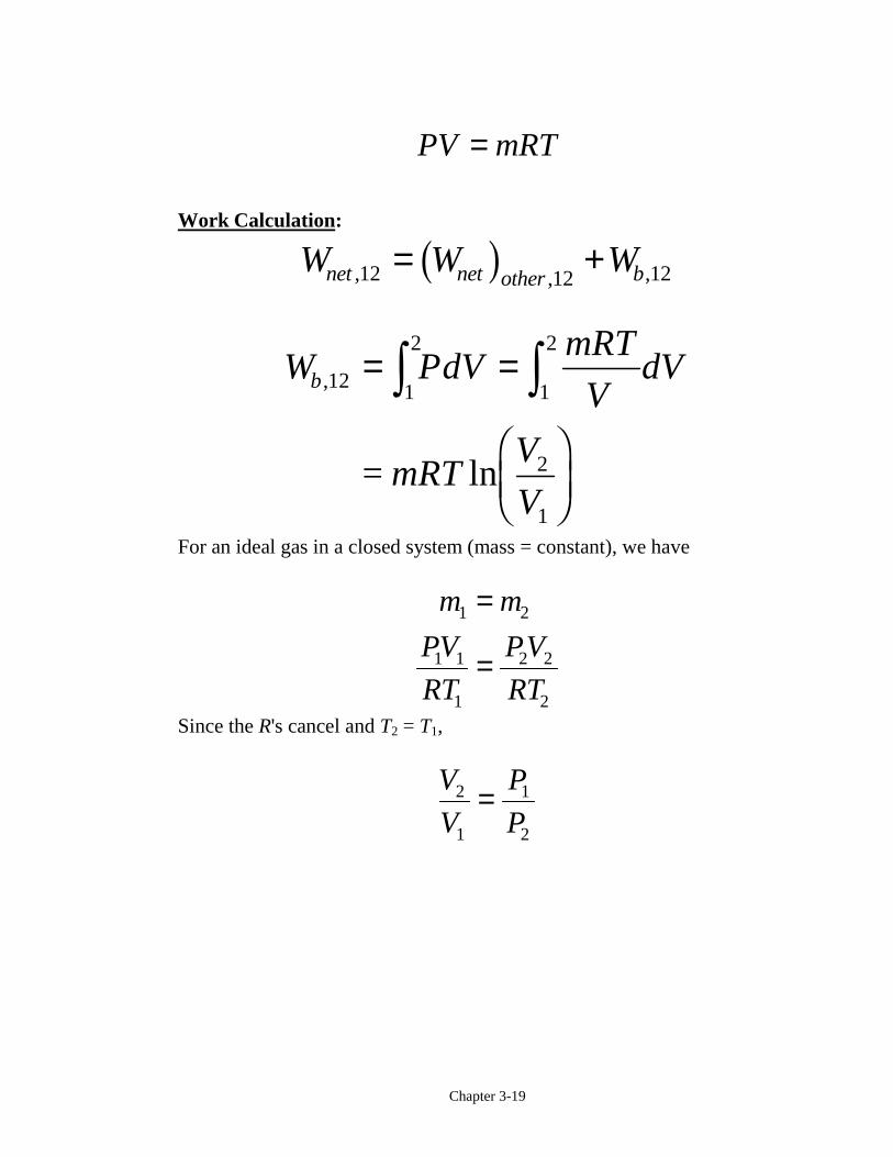
PV mRT=
Work Calculation:
W W Wnet net other b, , ,12 12 12= +b g
W PdVmRT
VdV
mRTV
V
b ,
ln
12 1
2
1
2
2
1
= =
FHGIKJ
z z=
For an ideal gas in a closed system (mass = constant), we have
m m
PV
RT
PV
RT
1 2
1 1
1
2 2
2
=
=
Since the R's cancel and T2 = T1,
V
V
P
P2
1
1
2
=
Chapter 3-20
W mRTP
P
kgkJ
kg KK
MPa
MPa
kJ
b, ln
( ) . ( ) ln.
.
.
121
2
3 0 2968 300015
0 30
184 5
=FHGIKJ
=−
FHG
IKJ
FHG
IKJ
= −
The net work is
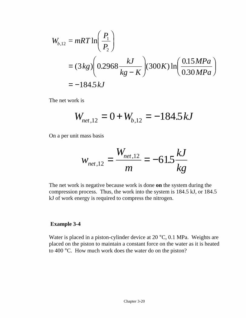
W W kJnet b, , .12 120 184 5= + = −
On a per unit mass basis
wW
m
kJ
kgnetnet
,, .1212 615= = −
The net work is negative because work is done on the system during thecompression process. Thus, the work into the system is 184.5 kJ, or 184.5kJ of work energy is required to compress the nitrogen.
Example 3-4
Water is placed in a piston-cylinder device at 20 °C, 0.1 MPa. Weights areplaced on the piston to maintain a constant force on the water as it is heatedto 400 °C. How much work does the water do on the piston?
Chapter 3-21
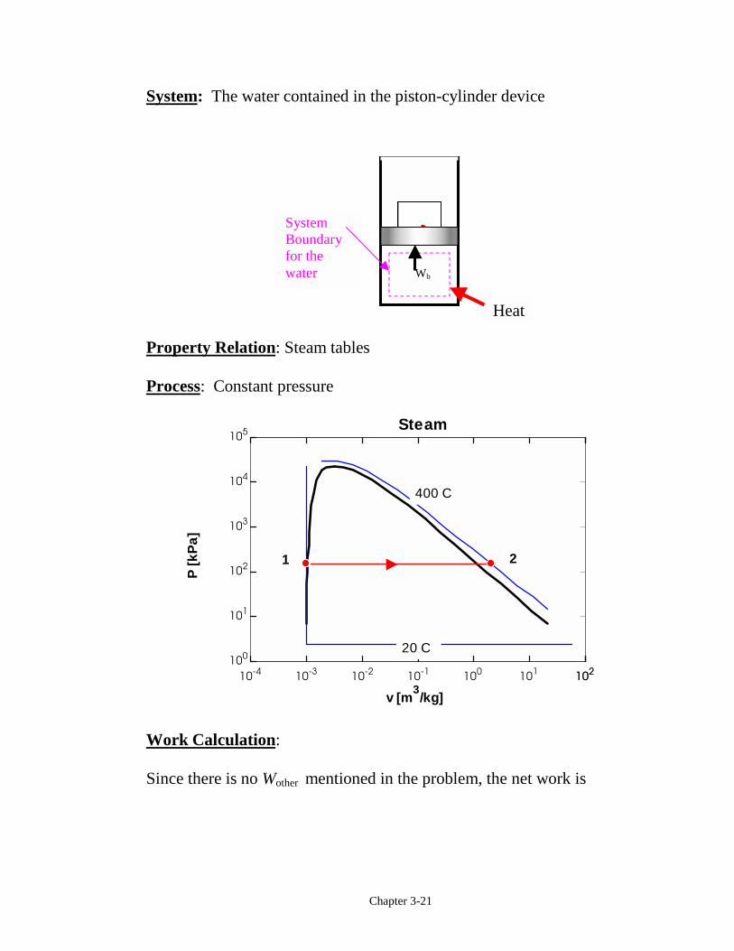
System: The water contained in the piston-cylinder device
Property Relation: Steam tables
Process: Constant pressure
10-4 10-3 10-2 10-1 100 101 102102100
101
102
103
104
105
v [m3/kg]
P [k
Pa]
400 C
20 C
Steam
1 2
Work Calculation:
Since there is no Wother mentioned in the problem, the net work is
Heat
SystemBoundaryfor thewater Wb
Chapter 3-22
W W PdV P dV P V Vnet b, ,12 12 1
2
1
2
2 1= = = = −z z b gSince the mass of the water is unknown, we calculate the work per unitmass.
wW
m
P V V
mP v vb
b,
,12
12 2 12 1= =
−= −
b g b gAt T1 = 20°C, Psat = 2.339 kPa. Since P1 > 2.339 kPa, state 1 iscompressed liquid. Thus,
v1 ≅ vf at 20 °C = 0.001002 m3/ kg
At P2 = P1 = 0.1 MPa, T2 > Tsat at 0.1 MPa = 99.63°C.
So, state 2 is superheated. Using the superheated tables,
v2 = 3.103 m3/kg
w P v v
MPam
kg
kPa
MPa
kJ
m kPa
kJ
kg
b,
. ( . . )
.
12 2 1
3 3
301 3103 0 00100210
310 2
= −
= −
=
b g
The water does work on the piston in the amount of 310.2 kJ/kg.
Chapter 3-23
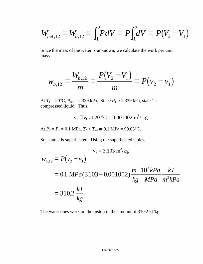
Example 3-5
One kilogram of water is contained in a piston-cylinder device at 100 °C.The piston rests on lower stops such that the volume occupied by the wateris 0.835 m3. The cylinder is fitted with an upper set of stops. When thepiston rests against the upper stops, the volume enclosed by the piston-cylinder device is 0.841 m3. A pressure of 200 kPa is required to supportthe piston. Heat is added to the water until the water exists as a saturatedvapor. How much work does the water do on the piston?
System: The water contained in the piston-cylinder device
Property Relation: Steam tables
Process: Combination of constant volume and constant pressure processesto be shown on the P-v diagram as the problem is solved
Work Calculation:
The specific volume at state 1 is
vV
m11 = =
0.835 m
1 kg= 0.835
m
kg
3 3
P
v
Water
Wb
SystemBoundary
Stops
Stops
Chapter 3-24
At T1 = 100°C,
vm
kgv
m
kgf g= . = .0 0010044 167293 3
Therefore, vf < v1 < vg and state 1 is in the saturation region; soP1 = 101.35 kPa.
Now let’s consider the processes for the water.
Process 1-2: The volume stays constant until the pressure increasesto 200 kPa. Then the piston will move.
v vm
kg2 1
3
0835= = .
Process 2-3: Piston lifts off the bottom stops while the pressure staysconstant. Does the piston hit the upper stops before orafter reaching the saturated vapor state?
Let's set
vV
m
m
kg
m
kg33
3 30841
10841 = =
.= .
At P3 = P2 = 200 kPa
vm
kgv
m
kgf g= . = .0 0010061 088573 3
Thus, vf < v3 < vg. So, the piston hits the upper stops before the waterreaches the saturated vapor state. Now we have to consider a third process.
Process 3-4: With the piston against the upper stops, the volumeremains constant during the final heating to thesaturated vapor state and the pressure increases.
Chapter 3-25
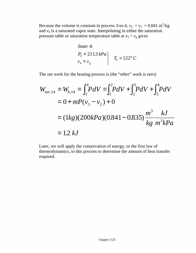
Because the volume is constant in process 3-to-4, v4 = v3 = 0.841 m3/kgand v4 is a saturated vapor state. Interpolating in either the saturationpressure table or saturation temperature table at v4 = vg gives
State
P kPa
v vT C
g
4
2113122
4
44
:
.==
UVW= °
The net work for the heating process is (the “other” work is zero)
W W PdV PdV PdV PdV
mP v v
kg kPam
kg
kJ
m kPa
kJ
net b, ,
( )
( )( )( . . )
.
14 14 1
4
1
2
2
3
3
4
3 2
3
3
0 0
1 200 0 841 0 835
12
= = = + +
= + − +
= −
=
z z z z
Later, we will apply the conservation of energy, or the first law ofthermodynamics, to this process to determine the amount of heat transferrequired.
Chapter 3-26
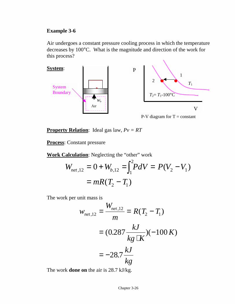
Example 3-6
Air undergoes a constant pressure cooling process in which the temperaturedecreases by 100°C. What is the magnitude and direction of the work forthis process?
System:
Property Relation: Ideal gas law, Pv = RT
Process: Constant pressure
Work Calculation: Neglecting the “other” work
W W PdV P V V
mR T T
net b, , ( )
( )
12 12 1
2
2 1
2 1
0= + = = −
= −z
The work per unit mass is
wW
mR T T
kJ
kg KK
kJ
kg
netnet
,, ( )
( . )( )
.
1212
2 1
0 287 100
28 7
= = −
=⋅
−
= −
The work done on the air is 28.7 kJ/kg.
Air
Wb
SystemBoundary
T1
T2= T1-100°C
P-V diagram for T = constant
P
V
21
Chapter 3-27
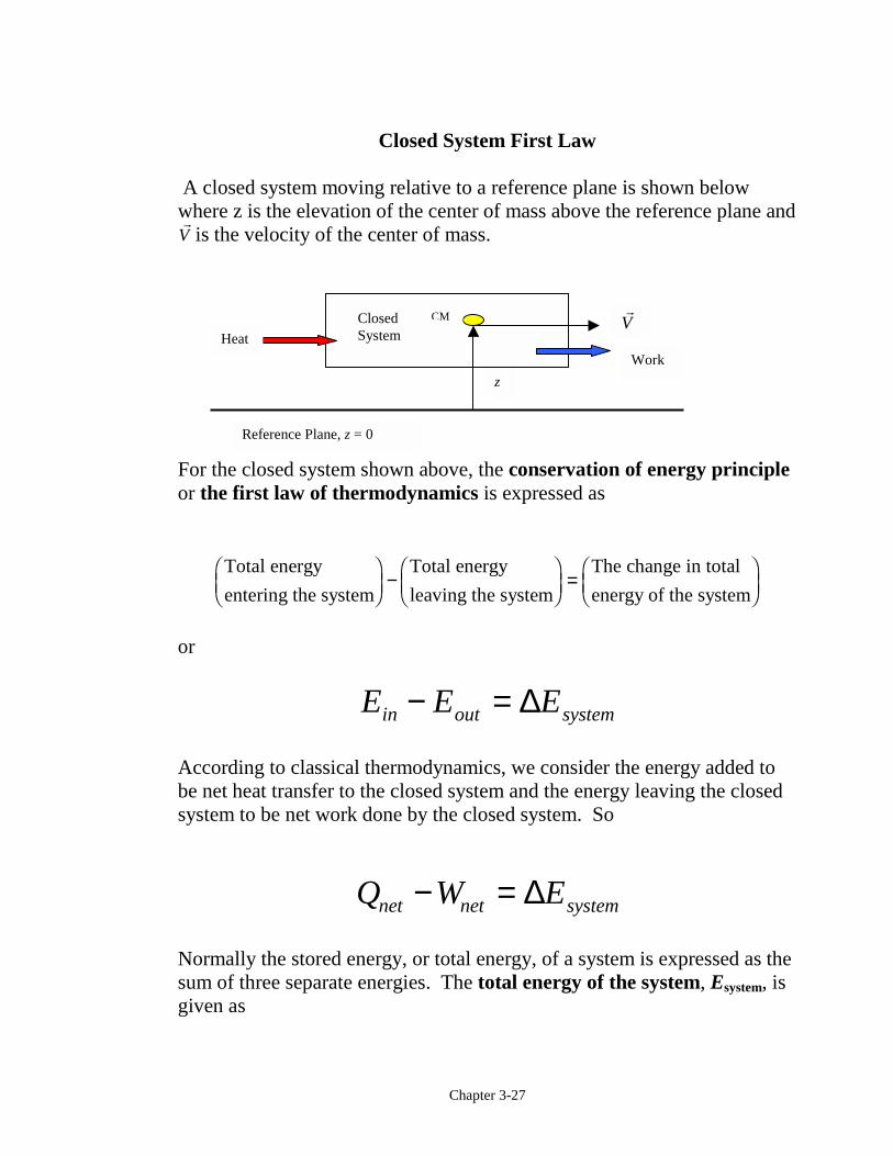
Closed System First Law
A closed system moving relative to a reference plane is shown belowwhere z is the elevation of the center of mass above the reference plane and"V is the velocity of the center of mass.
For the closed system shown above, the conservation of energy principleor the first law of thermodynamics is expressed as
Total energy
entering the system
Total energy
leaving the system
The change in total
energy of the system
FHG
IKJ −FHG
IKJ =FHG
IKJ
or
E E Ein out system− = ∆
According to classical thermodynamics, we consider the energy added tobe net heat transfer to the closed system and the energy leaving the closedsystem to be net work done by the closed system. So
Q W Enet net system− = ∆
Normally the stored energy, or total energy, of a system is expressed as thesum of three separate energies. The total energy of the system, Esystem, isgiven as
z
ClosedSystem
Reference Plane, z = 0
"V
Heat
Work
CM
Chapter 3-28
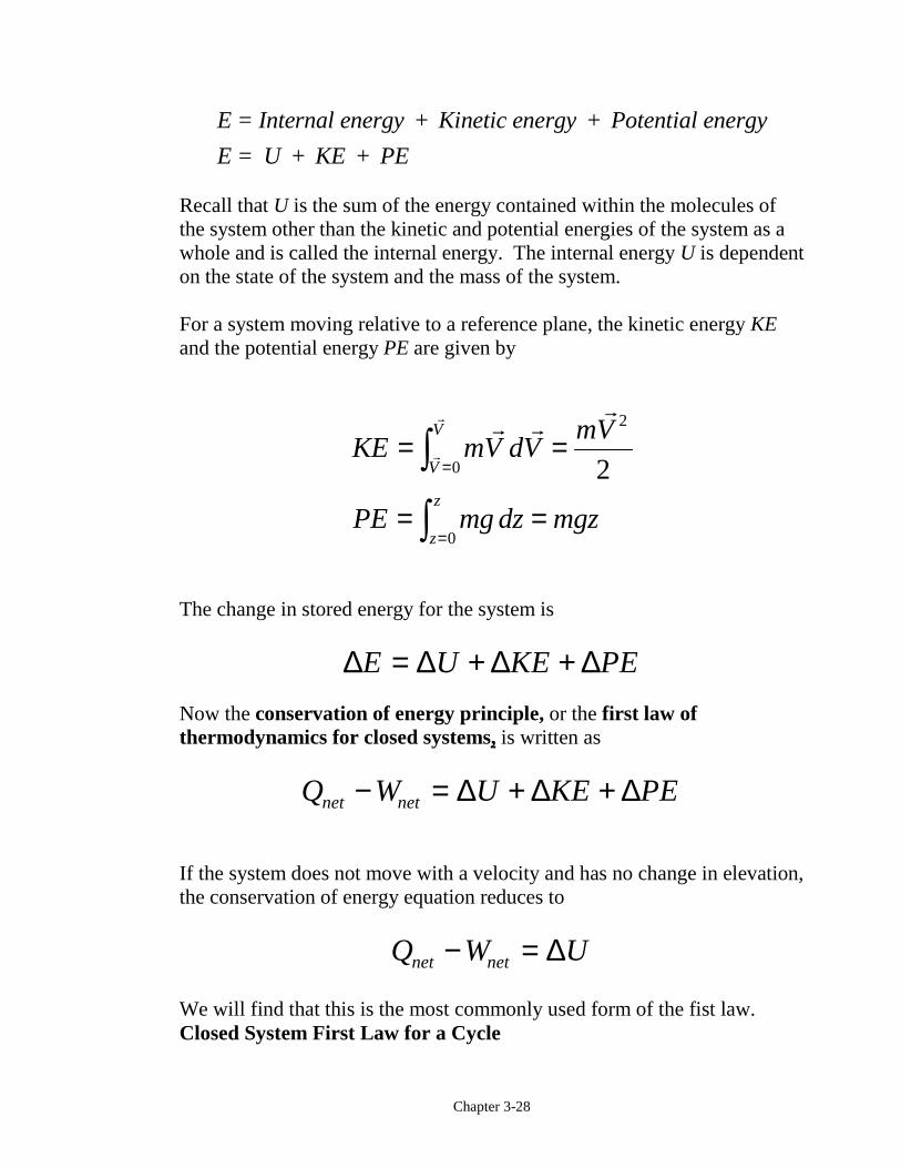
E Internal energy Kinetic energy Potential energy
E U KE PE
= + +
= + +
Recall that U is the sum of the energy contained within the molecules ofthe system other than the kinetic and potential energies of the system as awhole and is called the internal energy. The internal energy U is dependenton the state of the system and the mass of the system.
For a system moving relative to a reference plane, the kinetic energy KEand the potential energy PE are given by
KE mV dVmV
PE mg dz mgz
V
V
z
z
= =
= =
=
=
zz
" ""
"
" 2
0
0
2
The change in stored energy for the system is
∆ ∆ ∆ ∆E U KE PE= + +Now the conservation of energy principle, or the first law ofthermodynamics for closed systems, is written as
Q W U KE PEnet net− = + +∆ ∆ ∆
If the system does not move with a velocity and has no change in elevation,the conservation of energy equation reduces to
Q W Unet net− = ∆
We will find that this is the most commonly used form of the fist law.Closed System First Law for a Cycle
Chapter 3-29
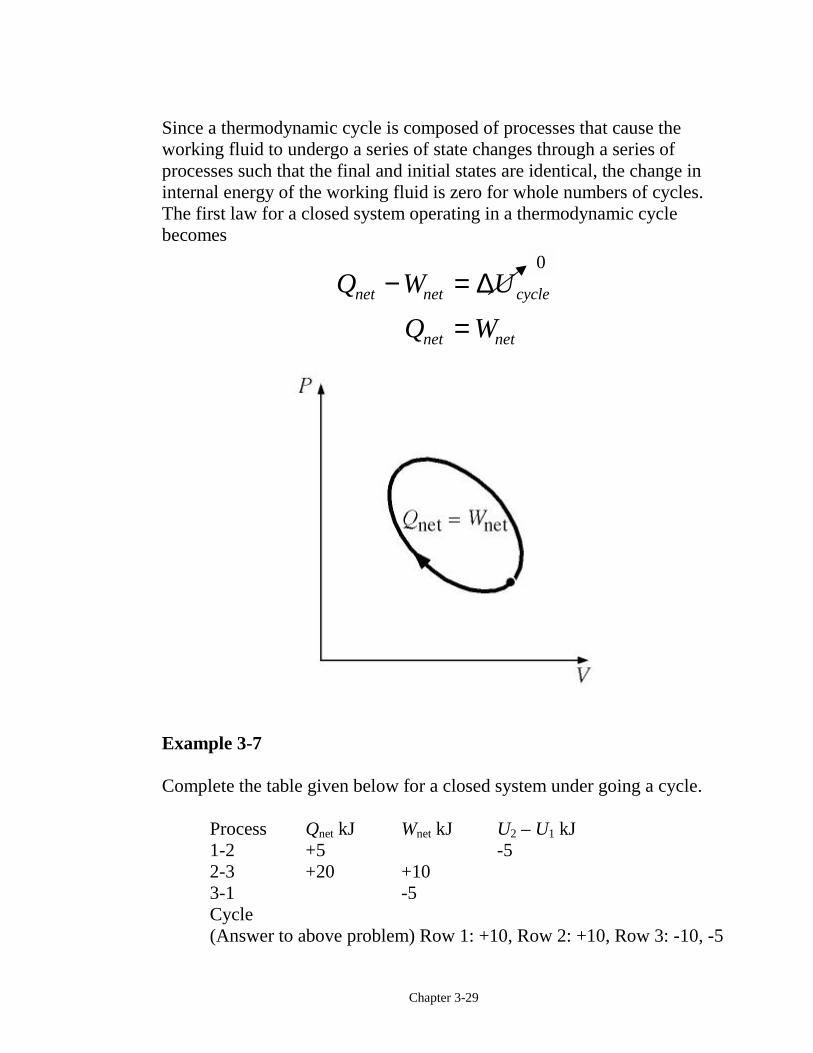
Since a thermodynamic cycle is composed of processes that cause theworking fluid to undergo a series of state changes through a series ofprocesses such that the final and initial states are identical, the change ininternal energy of the working fluid is zero for whole numbers of cycles.The first law for a closed system operating in a thermodynamic cyclebecomes
Q W U
Q W
net net cycle
net net
− ==
∆
Example 3-7
Complete the table given below for a closed system under going a cycle.
Process Qnet kJ Wnet kJ U2 – U1 kJ1-2 +5 -52-3 +20 +103-1 -5Cycle(Answer to above problem) Row 1: +10, Row 2: +10, Row 3: -10, -5
0
Chapter 3-30
Row 4: +15, +15, 0
Example 3-8Find the required heat transfer to the water in Example 3-5.
Review the solution procedure of Example 3-5 and then apply the first lawto the process.
Conservation of Energy:
E E E
Q W Uin out
net net
− =− =
∆∆, ,14 14 14
In Example 3-3 we found that
W kJnet , .14 12=
The heat transfer is obtained from the first law as
Q W Unet net, ,14 14 14= + ∆
where
∆U U U m u u14 4 1 4 1= − = −( )
At state 1, T1 = 100°C, v1 = 0.835 m3/kg and vf < v1 < vg at T1. Thequality at state 1 is
v v x v
xv v
v
f fg
f
fg
1 1
11 0835 0 001044
16729 0 0010440 499
= +
=−
= −−
=. .
. ..
Chapter 3-31
u u x u
kJ
kg
f fg1 1
418 94 0 499 2087 6
1460 26
= +
= +
=
. ( . )( . )
.
Because state 4 is a saturated vapor state and v4 = 0.841 m3/kg,interpolating in either the saturation pressure table or saturationtemperature table at v4 = vg gives
ukJ
kg4 253148= .
So
∆U m u u
kgkJ
kg
kJ
14 4 1
1 253148 1460 26
107122
= −
= −
=
( )
( )( . . )
.
The heat transfer is
Q W U
kJ kJ
kJ
net net, ,
. .
.
14 14 14
12 107122
1072 42
= += +=
∆
Heat in the amount of 1072.42 kJ is added to the water.
Chapter 3-32
Specific Heats, Internal Energy and Enthalpy
Before the first law of thermodynamics can be applied to systems, ways tocalculate the change in internal energy of the substance enclosed by thesystem boundary must be determined. For real substances like water, theproperty tables are used to find the internal energy change. For ideal gasesthe internal energy is found by knowing the specific heats. Physics definesthe amount of energy needed to raise the temperature of a unit of mass of asubstance one degree as the specific heat at constant volume CV for aconstant-volume process, and the specific heat at constant pressure CP for aconstant-pressure process. Recall that enthalpy h is the sum of the internalenergy u and the pressure-volume product Pv.
h u Pv= +
In thermodynamics, the specific heats are defined as
Cu
TC
h
TVv
PP
= ∂∂FHGIKJ = ∂
∂FHGIKJ and
Simple Substance
The thermodynamic state of a simple, homogeneous substance is specifiedby giving any two independent, intensive properties. Let's consider theinternal energy to be a function of T and v and the enthalpy to be a functionof T and P as follows:
u u T v= ( , ) and h = h(T, P)
The total differential of u is
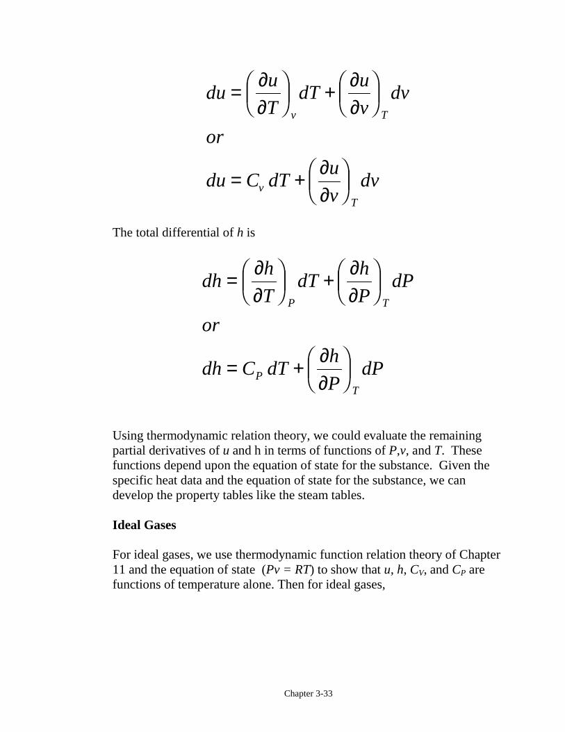
Chapter 3-33
duu
TdT
u
vdv
or
du C dTu
vdv
v T
vT
= ∂∂FHGIKJ + ∂
∂FHGIKJ
= + ∂∂FHGIKJ
The total differential of h is
dhh
TdT
h
PdP
or
dh C dTh
PdP
P T
PT
= ∂∂FHGIKJ + ∂
∂FHGIKJ
= + ∂∂FHGIKJ
Using thermodynamic relation theory, we could evaluate the remainingpartial derivatives of u and h in terms of functions of P,v, and T. Thesefunctions depend upon the equation of state for the substance. Given thespecific heat data and the equation of state for the substance, we candevelop the property tables like the steam tables.
Ideal Gases
For ideal gases, we use thermodynamic function relation theory of Chapter11 and the equation of state (Pv = RT) to show that u, h, CV, and CP arefunctions of temperature alone. Then for ideal gases,
Chapter 3-34
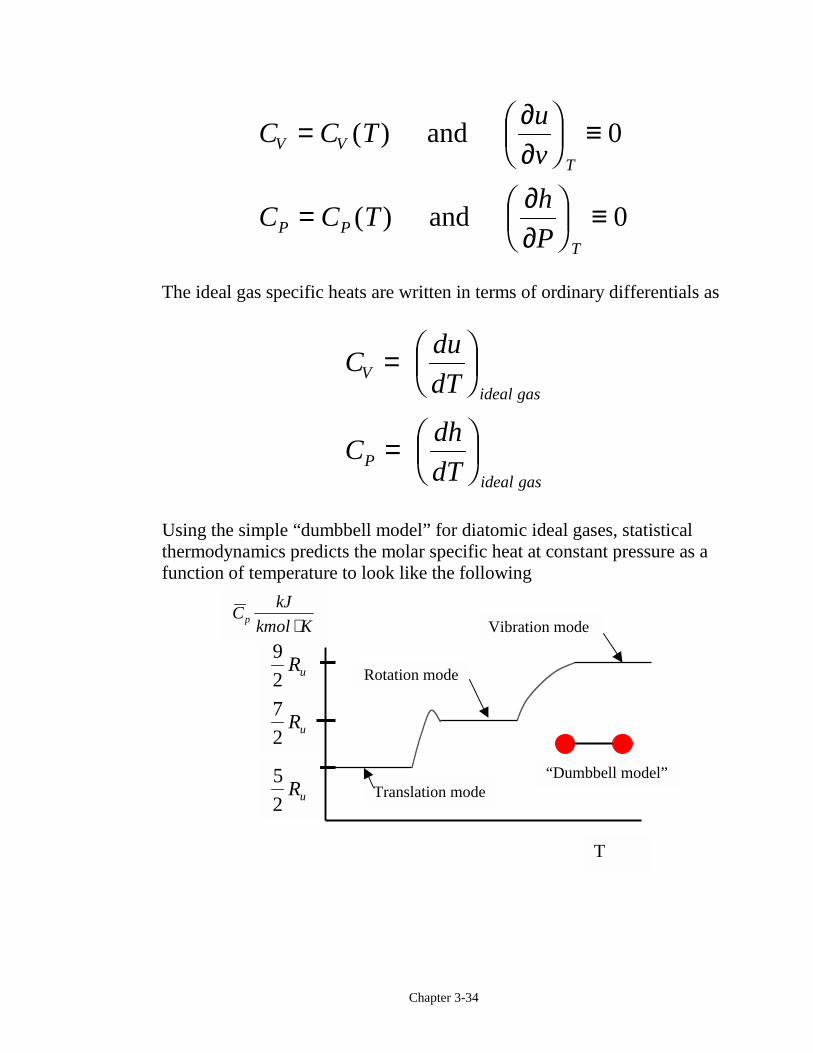
C C Tu
v
C C Th
P
V VT
P PT
= ∂∂FHGIKJ ≡
= ∂∂FHGIKJ ≡
( )
( )
and
and
0
0
The ideal gas specific heats are written in terms of ordinary differentials as
Cdu
dT
Cdh
dT
Videal gas
Pideal gas
= FHGIKJ
= FHGIKJ
Using the simple “dumbbell model” for diatomic ideal gases, statisticalthermodynamics predicts the molar specific heat at constant pressure as afunction of temperature to look like the following
CkJ
kmol Kp ⋅
5
2Ru
7
2Ru
9
2Ru
“Dumbbell model”
T
Translation mode
Vibration mode
Rotation mode
Chapter 3-35
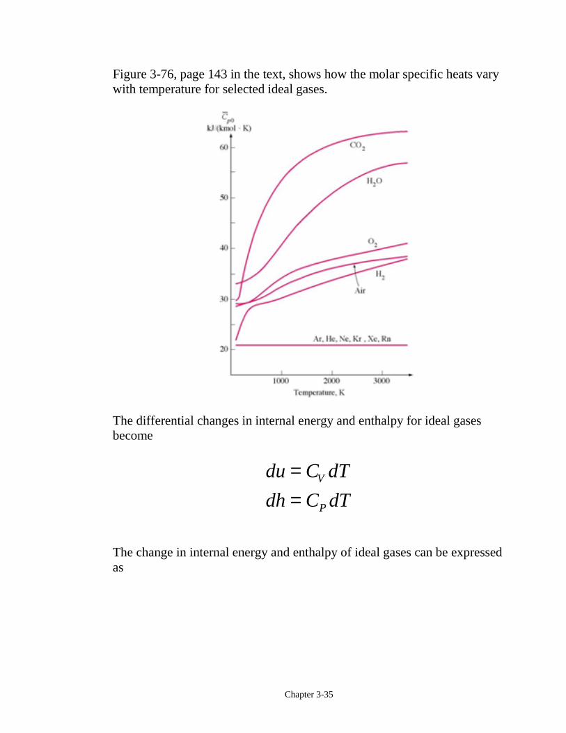
Figure 3-76, page 143 in the text, shows how the molar specific heats varywith temperature for selected ideal gases.
The differential changes in internal energy and enthalpy for ideal gasesbecome
du C dT
dh C dTV
P
==
The change in internal energy and enthalpy of ideal gases can be expressedas
Chapter 3-36
∆
∆
u u u C T dT C T T
h h h C T dT C T T
V V ave
P P ave
= − = = −
= − = = −
zz
2 1 1
2
2 1
2 1 1
2
2 1
( ) ( )
( ) ( )
,
,
where CV,ave and CP,ave are average or constant values of the specific heatsover the temperature range. We will drop the ave subscript shortly.
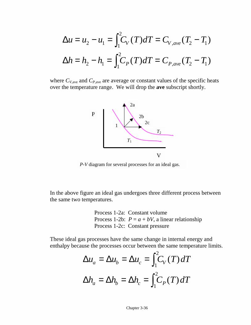
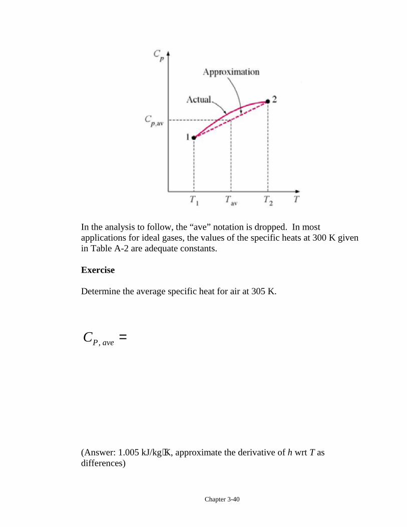
In the above figure an ideal gas undergoes three different process betweenthe same two temperatures.
Process 1-2a: Constant volumeProcess 1-2b: P = a + bV, a linear relationshipProcess 1-2c: Constant pressure
These ideal gas processes have the same change in internal energy andenthalpy because the processes occur between the same temperature limits.
∆ ∆ ∆
∆ ∆ ∆
u u u C T dT
h h h C T dT
a b c V
a b c P
= = =
= = =
zz
( )
( )
1
2
1
2
2a
T2
T1
2c1
P-V diagram for several processes for an ideal gas.
P
V
2b
Chapter 3-37
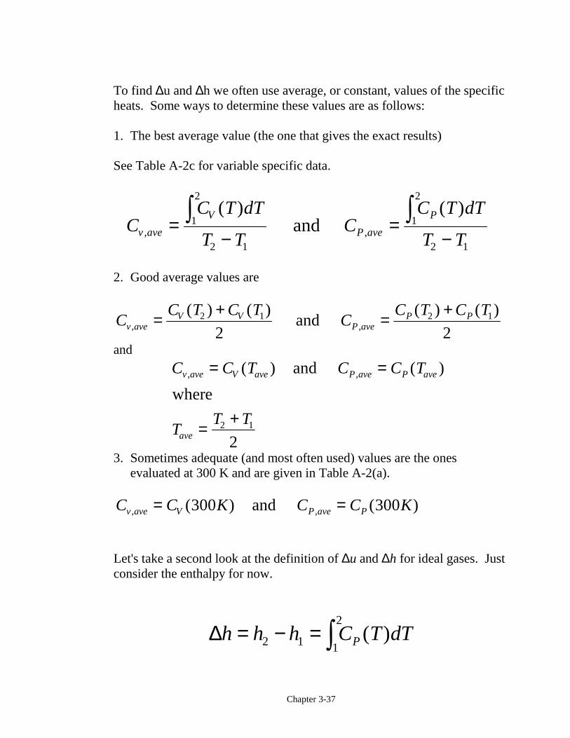
To find ∆u and ∆h we often use average, or constant, values of the specificheats. Some ways to determine these values are as follows:
1. The best average value (the one that gives the exact results)
See Table A-2c for variable specific data.
CC T dT
T TC
C T dT
T Tv ave
V
P ave
P
, ,
( ) ( )=
−=
−z z1
2
2 1
1
2
2 1
and
2. Good average values are
CC T C T
CC T C T
v aveV V
P aveP P
, ,
( ) ( ) ( ) ( )= + = +2 1 2 1
2 2 and
and
C C T C C T
TT T
v ave V ave P ave P ave
ave
, ,( ) ( )= =
= +
and
where
2 1
23. Sometimes adequate (and most often used) values are the ones
evaluated at 300 K and are given in Table A-2(a).
C C K C C Kv ave V P ave P, ,( ) ( )= =300 300 and
Let's take a second look at the definition of ∆u and ∆h for ideal gases. Justconsider the enthalpy for now.
∆h h h C T dTP= − = z2 1 1
2( )
Chapter 3-38
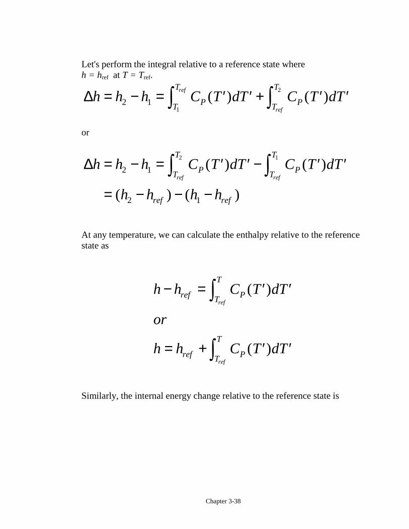
Let's perform the integral relative to a reference state whereh = href at T = Tref.
∆h h h C T dT C T dTPT
T
PT
Tref
ref
= − = ′ ′ + ′ ′z z2 11
2
( ) ( )
or
∆h h h C T dT C T dT
h h h h
PT
T
PT
T
ref ref
ref ref
= − = ′ ′ − ′ ′
= − − −
z z2 1
2 1
2 1
( ) ( )
( ) ( )
At any temperature, we can calculate the enthalpy relative to the referencestate as
h h C T dT
or
h h C T dT
ref PT
T
ref PT
T
ref
ref
− = ′ ′
= + ′ ′
z
z
( )
( )
Similarly, the internal energy change relative to the reference state is
Chapter 3-39
u u C T dT
or
u u C T dT
ref VT
T
ref VT
T
ref
ref
− = ′ ′
= + ′ ′
z
z
( )
( )
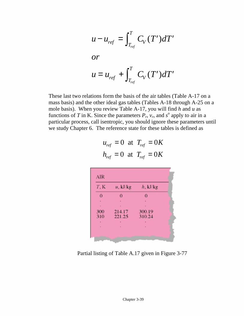
These last two relations form the basis of the air tables (Table A-17 on amass basis) and the other ideal gas tables (Tables A-18 through A-25 on amole basis). When you review Table A-17, you will find h and u asfunctions of T in K. Since the parameters Pr, vr, and so apply to air in aparticular process, call isentropic, you should ignore these parameters untilwe study Chapter 6. The reference state for these tables is defined as
u T K
h T K
ref ref
ref ref
= == =
0 0
0 0
at
at
Partial listing of Table A.17 given in Figure 3-77
Chapter 3-40
In the analysis to follow, the “ave” notation is dropped. In mostapplications for ideal gases, the values of the specific heats at 300 K givenin Table A-2 are adequate constants.
Exercise
Determine the average specific heat for air at 305 K.
CP ave, =
(Answer: 1.005 kJ/kg⋅K, approximate the derivative of h wrt T asdifferences)
Chapter 3-41
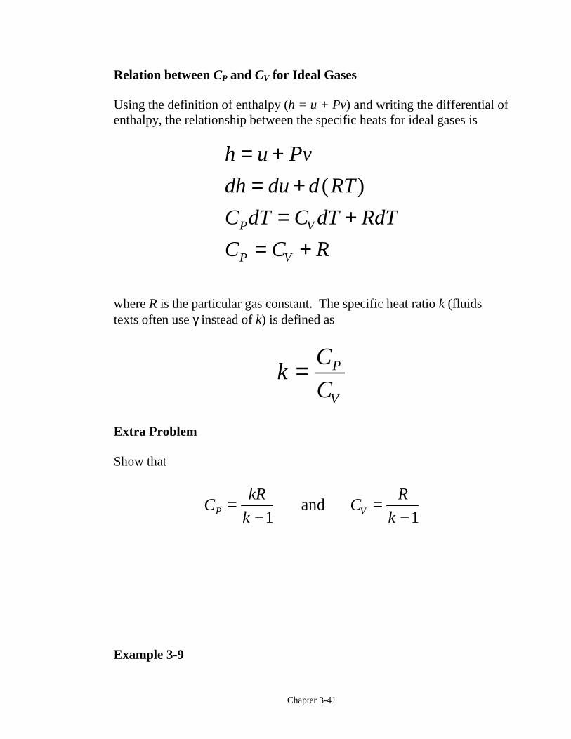
Relation between CP and CV for Ideal Gases
Using the definition of enthalpy (h = u + Pv) and writing the differential ofenthalpy, the relationship between the specific heats for ideal gases is
h u Pv
dh du d RT
C dT C dT RdT
C C RP V
P V
= += +
= += +
( )
where R is the particular gas constant. The specific heat ratio k (fluidstexts often use γ instead of k) is defined as
kC
CP
V
=
Extra Problem
Show that
CkR
kC
R
kP V=−
=−1 1
and
Example 3-9
Chapter 3-42
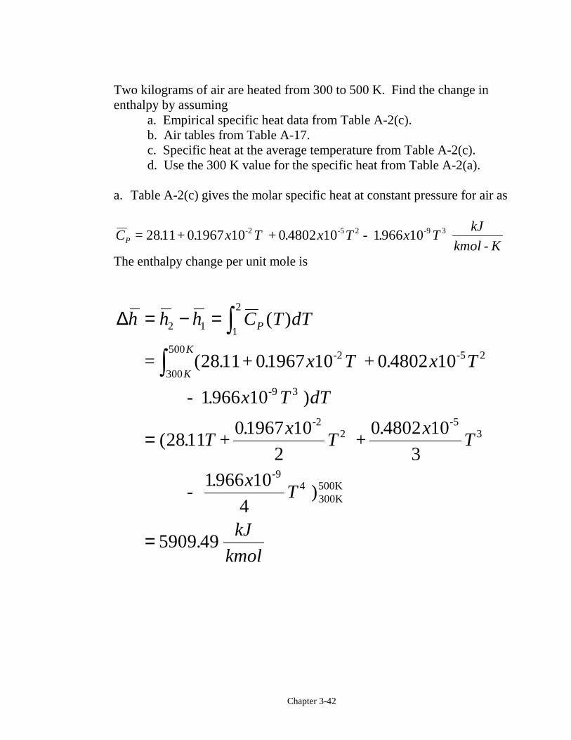
Two kilograms of air are heated from 300 to 500 K. Find the change inenthalpy by assuming
a. Empirical specific heat data from Table A-2(c).b. Air tables from Table A-17.c. Specific heat at the average temperature from Table A-2(c).d. Use the 300 K value for the specific heat from Table A-2(a).
a. Table A-2(c) gives the molar specific heat at constant pressure for air as
C x T x T x TkJ
kmol KP = . + . + . - . -
-2 -5 -92811 01967 10 0 4802 10 1966 102 3
The enthalpy change per unit mole is
∆h h h C T dT
x T x T
x T dT
Tx
Tx
T
xT
kJ
kmol
P
K
K
= − =
=
=
zz
2 1 1
2
2
300
500
3
2 3
4
2811 01967 10 0 4802 10
1966 10
281101967 10
2
0 4802 10
31966 10
4
5909 49
( )
(
(
.
= . + . + .
- . )
. +.
+.
- .
)
-2 -5
-9
-2 -5
-9
300K500K
Chapter 3-43
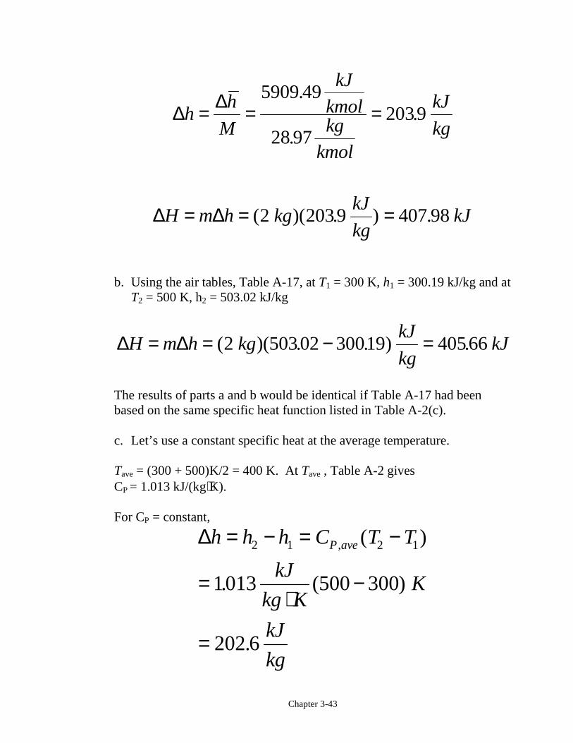
∆ ∆h
h
M
kJ
kmolkg
kmol
kJ
kg= = =
5909 49
28 972039
.
..
∆ ∆H m h kgkJ
kgkJ= = =( )( . ) .2 2039 407 98
b. Using the air tables, Table A-17, at T1 = 300 K, h1 = 300.19 kJ/kg and atT2 = 500 K, h2 = 503.02 kJ/kg
∆ ∆H m h kgkJ
kgkJ= = − =( )(503. . ) .2 02 30019 40566
The results of parts a and b would be identical if Table A-17 had beenbased on the same specific heat function listed in Table A-2(c).
c. Let’s use a constant specific heat at the average temperature.
Tave = (300 + 500)K/2 = 400 K. At Tave , Table A-2 givesCP = 1.013 kJ/(kg⋅K).
For CP = constant,
∆h h h C T T
kJ
kg KK
kJ
kg
P ave= − = −
=⋅
−
=
2 1 2 1
1013 300
202 6
, ( )
. (500 )
.
Chapter 3-44
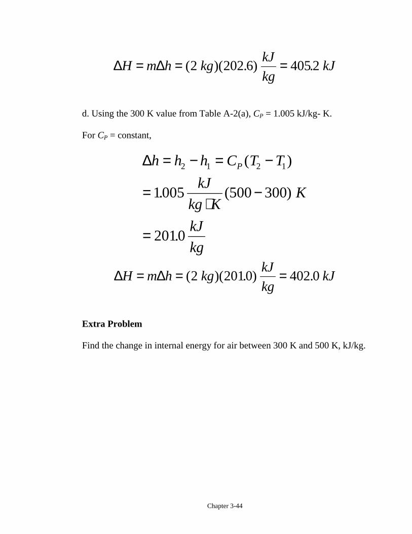
∆ ∆H m h kgkJ
kgkJ= = =( )( . ) .2 202 6 4052
d. Using the 300 K value from Table A-2(a), CP = 1.005 kJ/kg- K.
For CP = constant,
∆h h h C T T
kJ
kg KK
kJ
kg
P= − = −
=⋅
−
=
2 1 2 1
1005 300
2010
( )
. (500 )
.
∆ ∆H m h kgkJ
kgkJ= = =( )( . ) .2 2010 402 0
Extra Problem
Find the change in internal energy for air between 300 K and 500 K, kJ/kg.
Chapter 3-45
The Systematic Thermodynamics Solution Procedure
When we apply a methodical solution procedure, thermodynamicsproblems are relatively easy to solve. Each thermodynamics problem isapproached the same way as shown in the following, which is amodification of the procedure given in the text:
Thermodynamics Solution Method1. Sketch the system and show energy interactions across the
boundaries.
2. Determine the property relation. Is the working substancean ideal gas or a real substance? Begin to set up and fill ina property table.
3. Determine the process and sketch the process diagram.Continue to fill in the property table.
4. Apply conservation of mass and conservation of energyprinciples.
5. Bring in other information from the problem statement,called physical constraints, such as the volume doubles orthe pressure is halved during the process.
6. Develop enough equations for the unknowns and solve.
Chapter 3-46
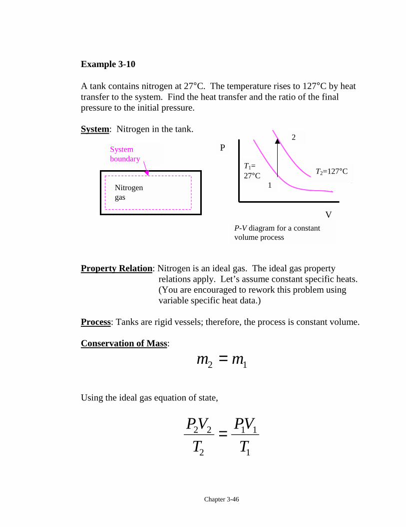
Example 3-10
A tank contains nitrogen at 27°C. The temperature rises to 127°C by heattransfer to the system. Find the heat transfer and the ratio of the finalpressure to the initial pressure.
System: Nitrogen in the tank.
Property Relation: Nitrogen is an ideal gas. The ideal gas propertyrelations apply. Let’s assume constant specific heats.(You are encouraged to rework this problem usingvariable specific heat data.)
Process: Tanks are rigid vessels; therefore, the process is constant volume.
Conservation of Mass:
m m2 1=
Using the ideal gas equation of state,
PV
T
PV
T2 2
2
1 1
1
=
Nitrogengas
Systemboundary
2
T2=127°CT1=27°C
1
P-V diagram for a constantvolume process
P
V
Chapter 3-47
Since R is the particular gas constant, and the process is constant volume,
V V
P
P
T
T
K
K
2 1
2
1
2
1
127 273
27 2731333
=
= = ++
=( )
( ).
Conservation of Energy:
The first law closed system is
E E E
Q W Uin out
net net
− =− =
∆∆
For nitrogen undergoing a constant volume process (dV = 0), the net workis (Wother = 0)
W W PdVnet b, ,12 12 1
20 0= + = =z
Using the ideal gas relations with Wnet = 0, the first law becomes (constantspecific heats)
Q U m C dT mC T Tnet V V− = = = −z01
2
2 1∆ ( )
The heat transfer per unit mass is
Chapter 3-48
mC T T
kJ
kg KK
kJ
kg
netnet
V= = −
=⋅
−
=
( )
.
.
2 1
0 743 127 27
74 3
b g
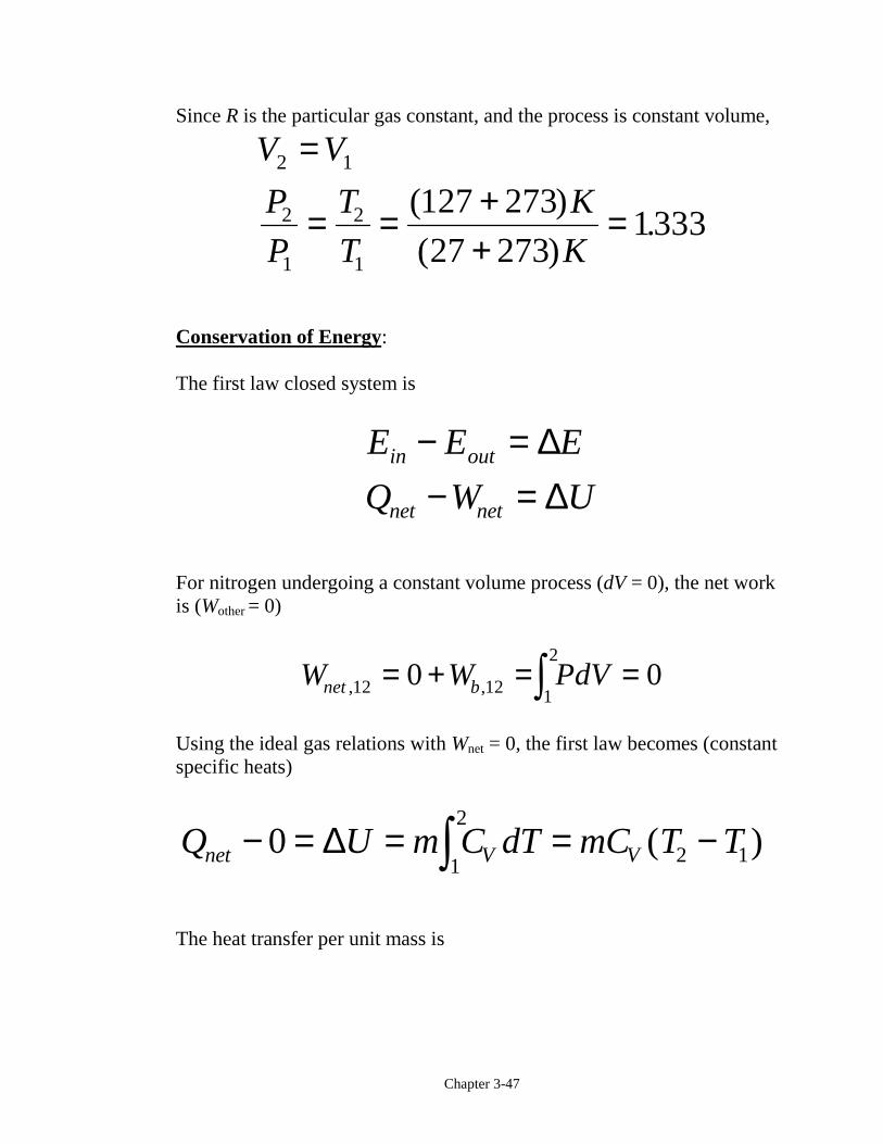
Example 3-11
Air is expanded isothermally at 100°C from 0.4 MPa to 0.1 MPa. Find theratio of the final to the initial volume, the heat transfer, and work.
System: Air contained in a piston-cylinder device, a closed system
Process: Constant temperature
Property Relation: Assume air is an ideal gas and use the ideal gasproperty relations with constant specific heats.
P-V diagram for T = constant
P
V
2
1
Air WbT = const.
Systemboundary
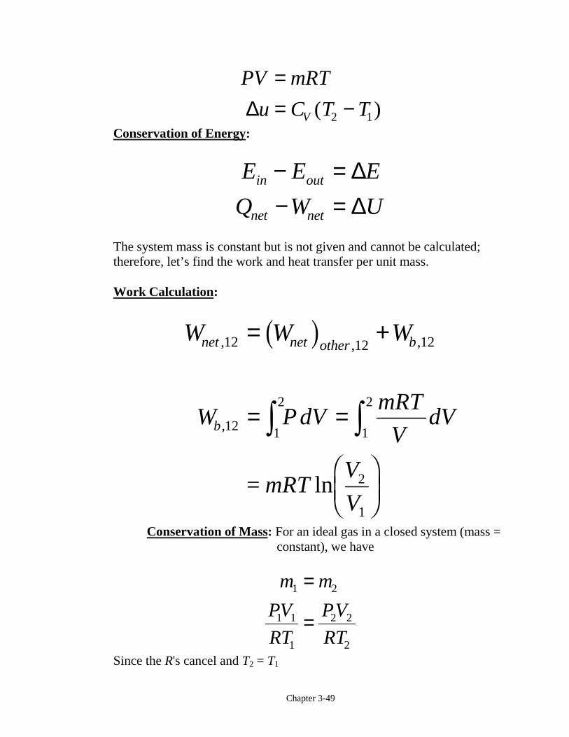
Chapter 3-49
PV mRT
u C T TV
== −∆ ( )2 1
Conservation of Energy:
E E E
Q W Uin out
net net
− =− =
∆∆
The system mass is constant but is not given and cannot be calculated;therefore, let’s find the work and heat transfer per unit mass.
Work Calculation:
W W Wnet net other b, , ,12 12 12= +b g
W P dVmRT
VdV
mRTV
V
b ,
ln
12 1
2
1
2
2
1
= =
FHGIKJ
z z=
Conservation of Mass: For an ideal gas in a closed system (mass =constant), we have
m m
PV
RT
PV
RT
1 2
1 1
1
2 2
2
=
=
Since the R's cancel and T2 = T1
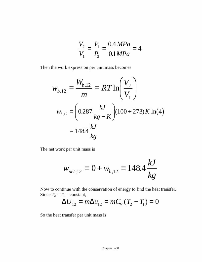
Chapter 3-50
V
V
P
P
MPa
MPa2
1
1
2
0 4
014= = =.
.
Then the work expression per unit mass becomes
w
W
mRT
V
Vbb
,, ln1212 2
1
= =FHGIKJ
wkJ
kg KK
kJ
kg
b, . ( ) ln
.
12 0 287 100 273 4
148 4
=−
FHG
IKJ +
=
b g
The net work per unit mass is
w wkJ
kgnet b, , .12 120 148 4= + =
Now to continue with the conservation of energy to find the heat transfer.Since T2 = T1 = constant,
∆ ∆U m u mC T TV12 12 2 1 0= = − =( )
So the heat transfer per unit mass is
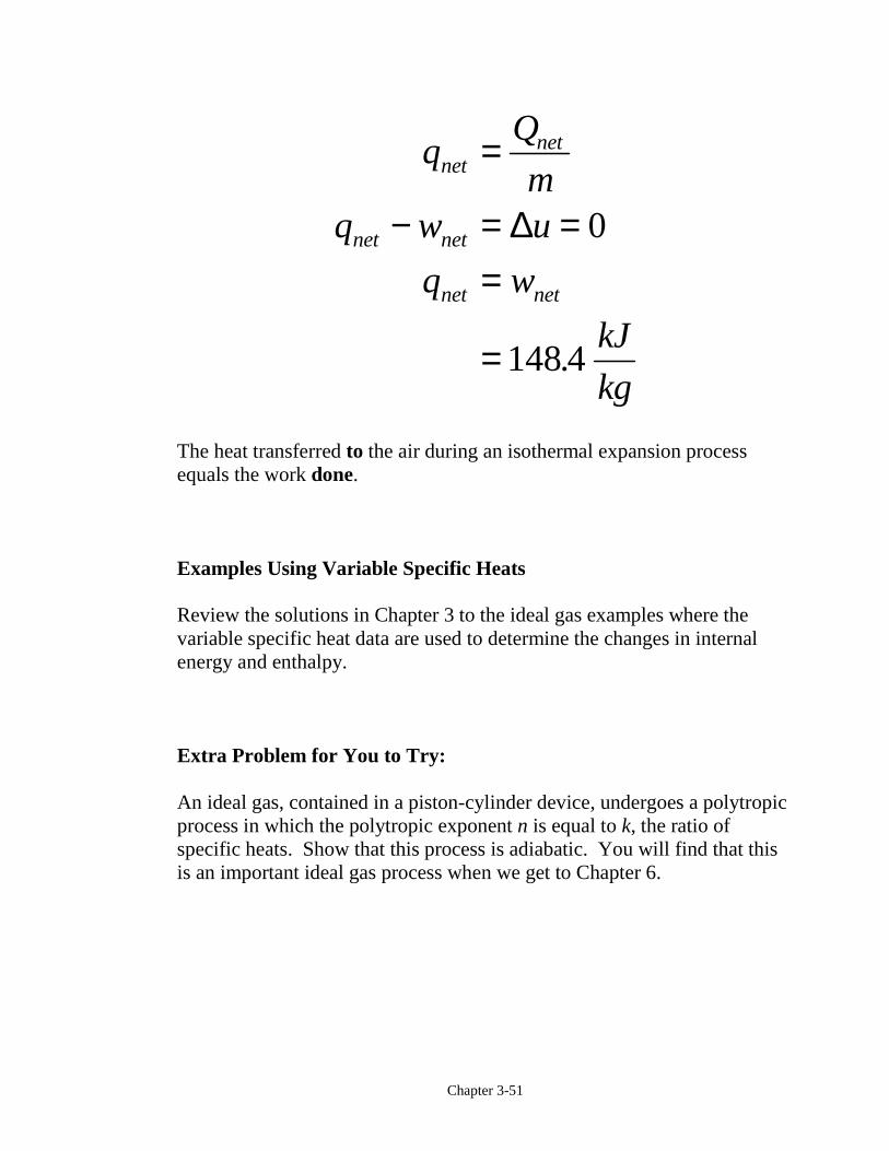
Chapter 3-51
mq w u
q w
kJ
kg
netnet
net net
net net
=
− = ==
=
∆ 0
148 4.
The heat transferred to the air during an isothermal expansion processequals the work done.
Examples Using Variable Specific Heats
Review the solutions in Chapter 3 to the ideal gas examples where thevariable specific heat data are used to determine the changes in internalenergy and enthalpy.
Extra Problem for You to Try:
An ideal gas, contained in a piston-cylinder device, undergoes a polytropicprocess in which the polytropic exponent n is equal to k, the ratio ofspecific heats. Show that this process is adiabatic. You will find that thisis an important ideal gas process when we get to Chapter 6.
Chapter 3-52
Solids and Liquids
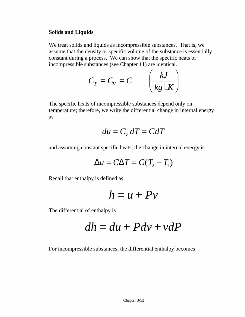
We treat solids and liquids as incompressible substances. That is, weassume that the density or specific volume of the substance is essentiallyconstant during a process. We can show that the specific heats ofincompressible substances (see Chapter 11) are identical.
C C CkJ
kg KP V= =⋅
FHGIKJ
The specific heats of incompressible substances depend only ontemperature; therefore, we write the differential change in internal energyas
du C dT CdTV= =
and assuming constant specific heats, the change in internal energy is
∆ ∆u C T C T T= = −( )2 1
Recall that enthalpy is defined as
h u Pv= +The differential of enthalpy is
dh du Pdv vdP= + +
For incompressible substances, the differential enthalpy becomes
Chapter 3-53
dv
dh du Pdv vdP
dh du vdP
=
= + / += +
00
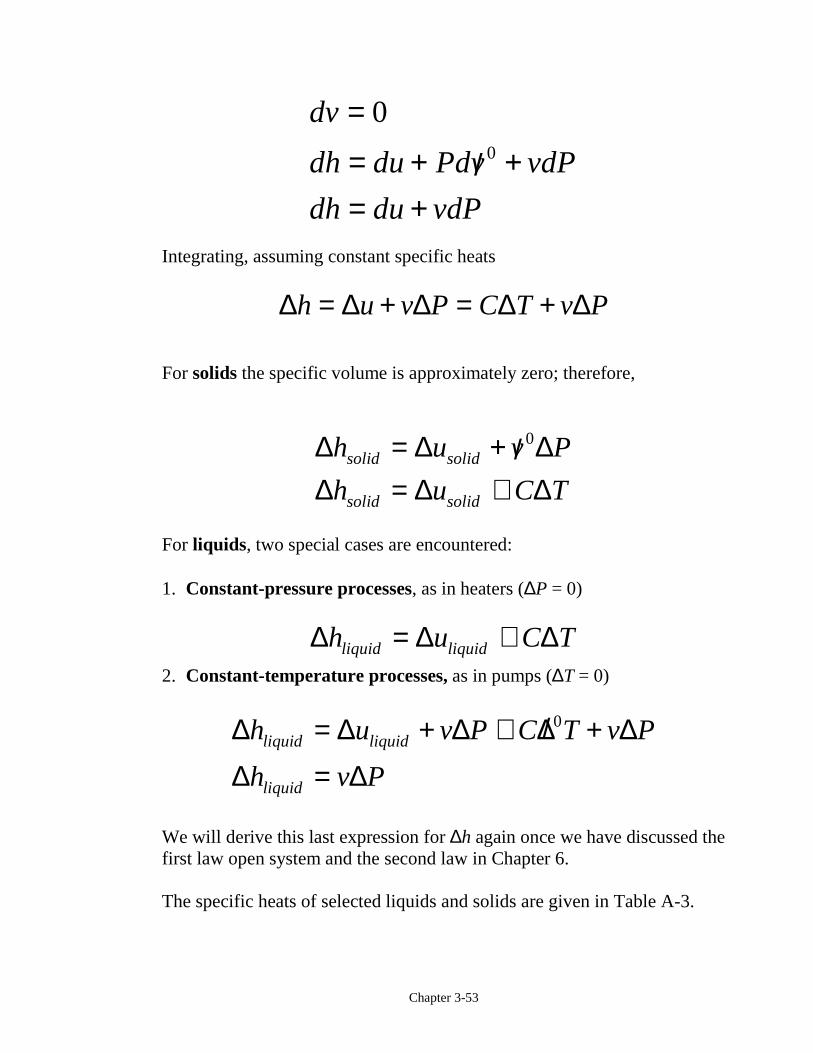
Integrating, assuming constant specific heats
∆ ∆ ∆ ∆ ∆h u v P C T v P= + = +
For solids the specific volume is approximately zero; therefore,
∆ ∆ ∆∆ ∆ ∆
h u v P
h u C Tsolid solid
solid solid
= + /= ≅
0
For liquids, two special cases are encountered:
1. Constant-pressure processes, as in heaters (∆P = 0)
∆ ∆ ∆h u C Tliquid liquid= ≅2. Constant-temperature processes, as in pumps (∆T = 0)
∆ ∆ ∆ ∆ ∆
∆ ∆
h u v P C T v P
h v Pliquid liquid
liquid
= + ≅ / +
=
0
We will derive this last expression for ∆h again once we have discussed thefirst law open system and the second law in Chapter 6.
The specific heats of selected liquids and solids are given in Table A-3.
Chapter 3-54
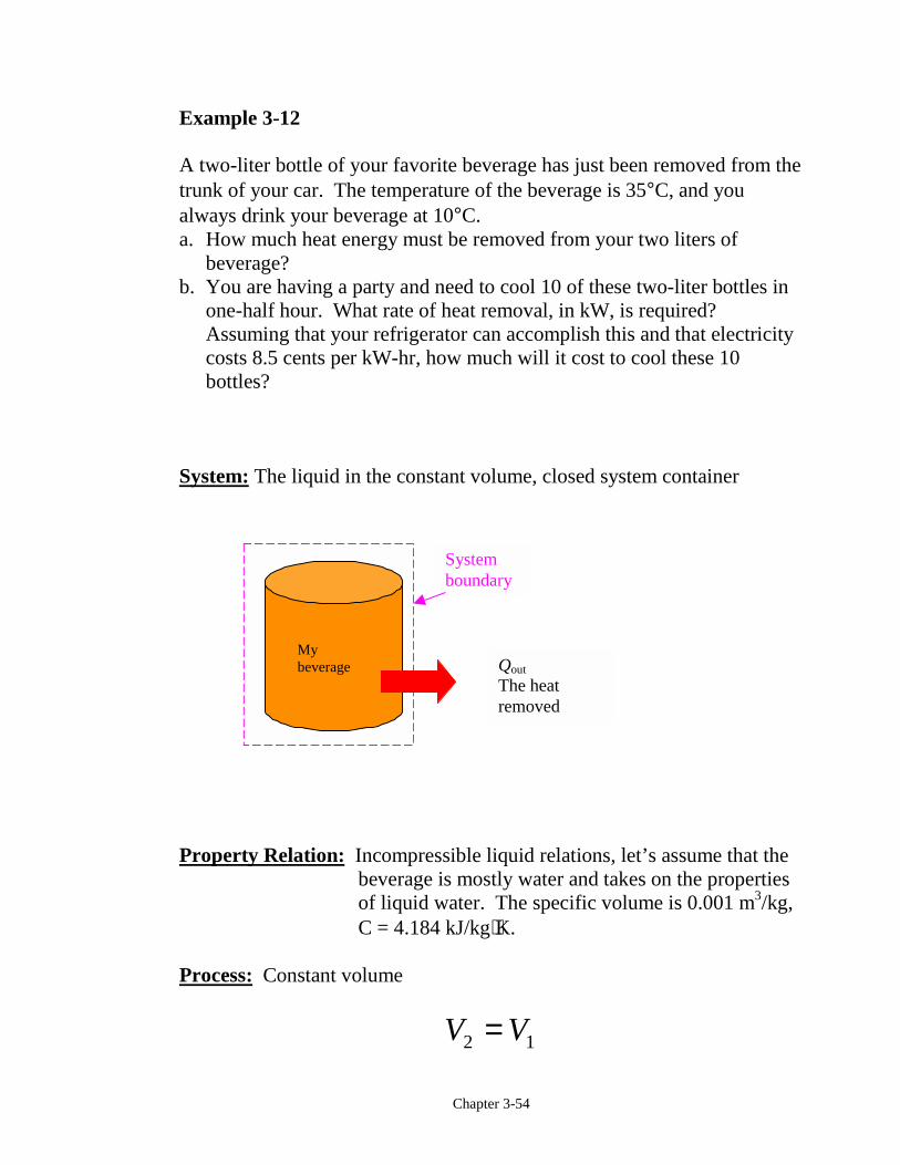
Example 3-12
A two-liter bottle of your favorite beverage has just been removed from thetrunk of your car. The temperature of the beverage is 35°C, and youalways drink your beverage at 10°C.a. How much heat energy must be removed from your two liters of
beverage?b. You are having a party and need to cool 10 of these two-liter bottles in
one-half hour. What rate of heat removal, in kW, is required?Assuming that your refrigerator can accomplish this and that electricitycosts 8.5 cents per kW-hr, how much will it cost to cool these 10bottles?
System: The liquid in the constant volume, closed system container
Property Relation: Incompressible liquid relations, let’s assume that thebeverage is mostly water and takes on the propertiesof liquid water. The specific volume is 0.001 m3/kg,C = 4.184 kJ/kg⋅K.
Process: Constant volume
V V2 1=
Qout
The heatremoved
Systemboundary
Mybeverage
Chapter 3-55
Conservation of Mass:
m m m
mV
v
L
mkg
m
Lkg
2 1
3
32
0 0011000
2
= =
= =FHG
IKJ =
.
Conservation of Energy:
The first law closed system is
E E Ein out− = ∆
Since the container is constant volume and there is no “other” work doneon the container during the cooling process, we have
W W Wnet net other b= + =b g 0
The only energy crossing the boundary is the heat transfer leaving thecontainer. Assuming the container to be stationary, the conservation ofenergy becomes
− =− = =
E E
Q U mC Tout
out
∆∆ ∆
Chapter 3-56
− =⋅
−
− = −=
Q kgkJ
kg KK
Q kJ
Q kJ
out
out
out
( )( . )( )
.
.
2 4181 10 35
209 2
209 2
The heat transfer rate to cool the 10 bottles in one-half hour is
!( )( . )
.
.
Qbottles
kJ
bottlehr
hr
s
kWkJ
skW
out = FHGIKJF
HGGG
I
KJJJ
=
10 209 2
05
1
3600
1162
Cost kW hrkW hr
=−
=
( . )( . )$0.
$0.
1162 0 5085
05
![L 20 Thermodynamics [5] heat, work, and internal energy heat, work, and internal energy the 1 st law of thermodynamics the 1 st law of thermodynamics the](https://img.pdfslide.us/doc/110x75/56649e5f5503460f94b59f3f/l-20-thermodynamics-5-heat-work-and-internal-energy-heat-work-and-internal.jpg)


![L 20 Thermodynamics [5] heat, work, and internal energy the 1 st law of thermodynamics the 2 nd law of thermodynamics Heat engines order to disorder](https://img.pdfslide.us/doc/110x75/56649e5d5503460f94b569ee/l-20-thermodynamics-5-heat-work-and-internal-energy-the-1-st-law-of-thermodynamics.jpg)