Embed Size (px)
DESCRIPTION
Chapter 3: Standard Single Purpose Processors - Peripherals. Introduction. Single-purpose processors Performs specific computation task Custom single-purpose processors Designed by us for a unique task Standard single-purpose processors “Off-the-shelf” -- pre-designed for a common task - PowerPoint PPT Presentation
Citation preview
Embedded Systems Design: A Unified Hardware/Software Introduction
1
Chapter 3: Standard Single Purpose Processors - Peripherals
Embedded Systems Design: A Unified Hardware/Software Introduction, (c) 2000 Vahid/Givargis
2
Introduction
• Single-purpose processors– Performs specific computation task
– Custom single-purpose processors• Designed by us for a unique task
– Standard single-purpose processors• “Off-the-shelf” -- pre-designed for a common task
• a.k.a., peripherals
• serial transmission
• analog/digital conversions
Embedded Systems Design: A Unified Hardware/Software Introduction, (c) 2000 Vahid/Givargis
3
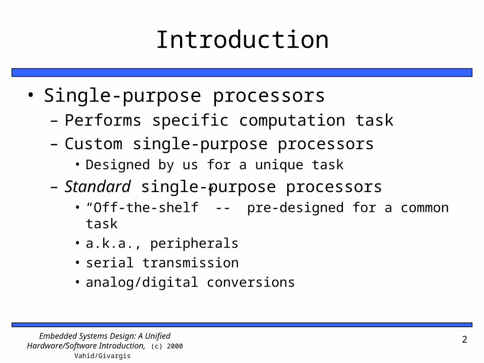
Timers, counters, watchdog timers
• Timer: measures time intervals– To generate timed output events
• e.g., hold traffic light green for 10 s
– To measure input events• e.g., measure a car’s speed
• Based on counting clock pulses• E.g., let Clk period be 10 ns
• And we count 20,000 Clk pulses
• Then 200 microseconds have passed
• 16-bit counter would count up to 65,535*10 ns = 655.35 microsec., resolution = 10 ns
• Top: indicates top count reached, wrap-around
16-bit up counter
Clk Cnt
Basic timer
Top
Reset
16
Embedded Systems Design: A Unified Hardware/Software Introduction, (c) 2000 Vahid/Givargis
4
Counters
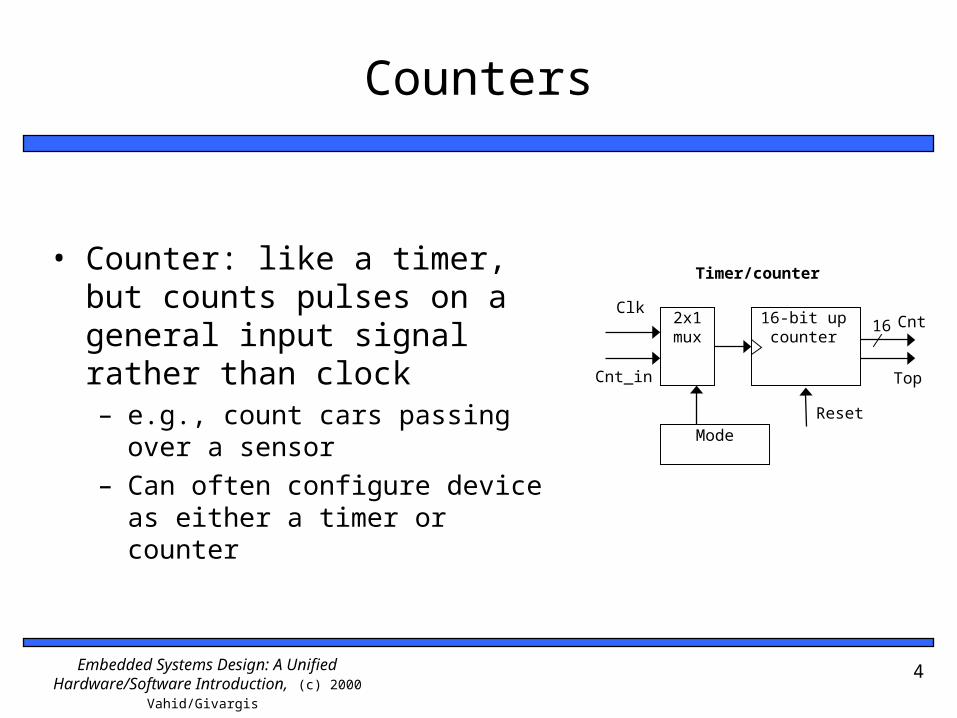
• Counter: like a timer, but counts pulses on a general input signal rather than clock– e.g., count cars passing over a sensor
– Can often configure device as either a timer or counter
16-bit up counter
Clk16
Cnt_in
2x1 mux
Mode
Timer/counter
Top
Reset
Cnt
Embedded Systems Design: A Unified Hardware/Software Introduction, (c) 2000 Vahid/Givargis
5
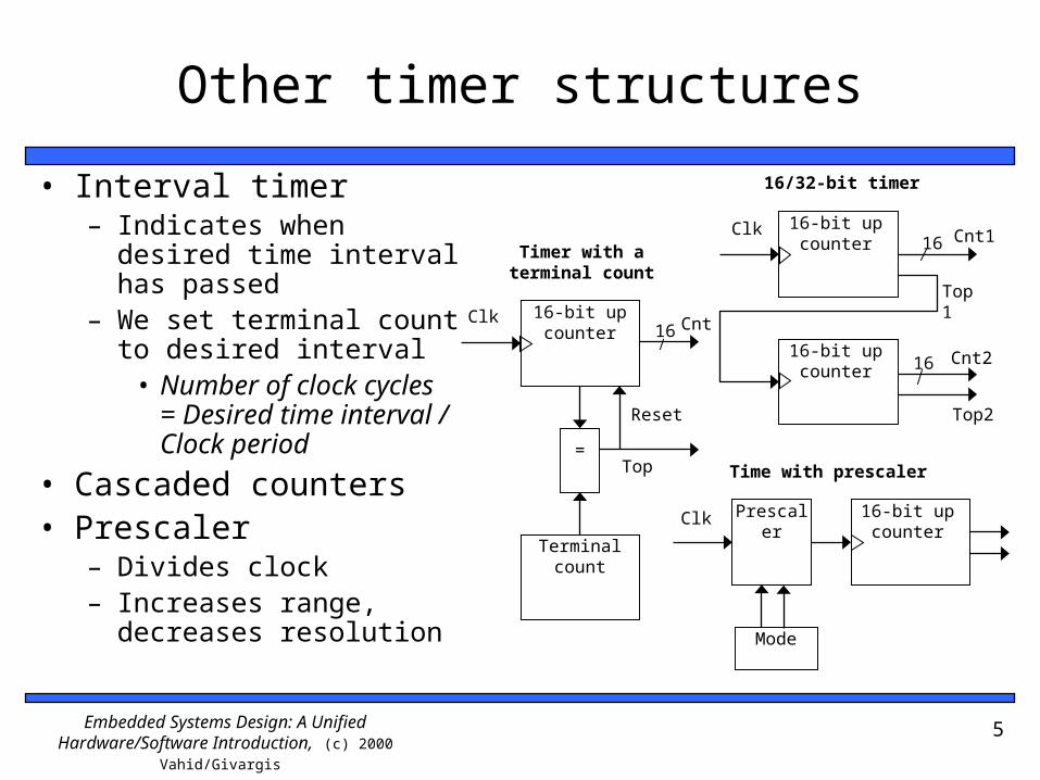
Other timer structures
Top2
Time with prescaler
16-bit up counter
Clk Prescaler
Mode
• Interval timer– Indicates when desired time
interval has passed– We set terminal count to
desired interval• Number of clock cycles
= Desired time interval / Clock period
• Cascaded counters• Prescaler
– Divides clock– Increases range, decreases
resolution
16-bit up counter
Clk16
Terminal count
=Top
Reset
Timer with a terminal count
Cnt
16-bit up counter
Clk
16-bit up counter
16
Cnt2
Top1
16/32-bit timer
Cnt1
16
Embedded Systems Design: A Unified Hardware/Software Introduction, (c) 2000 Vahid/Givargis
6
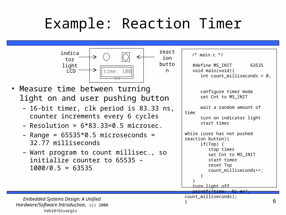
Example: Reaction Timer
indicator light
reaction button
time: 100 msLCD
/* main.c */
#define MS_INIT 63535 void main(void){ int count_milliseconds = 0; configure timer mode set Cnt to MS_INIT
wait a random amount of time turn on indicator light start timer
while (user has not pushed reaction button){ if(Top) { stop timer set Cnt to MS_INIT start timer reset Top count_milliseconds++; } } turn light off printf(“time: %i ms“, count_milliseconds);}
• Measure time between turning light on and user pushing button– 16-bit timer, clk period is 83.33 ns, counter
increments every 6 cycles– Resolution = 6*83.33=0.5 microsec.– Range = 65535*0.5 microseconds = 32.77
milliseconds– Want program to count millisec., so initialize
counter to 65535 – 1000/0.5 = 63535
Embedded Systems Design: A Unified Hardware/Software Introduction, (c) 2000 Vahid/Givargis
7
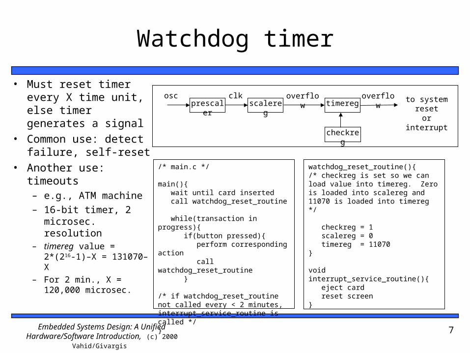
Watchdog timer
scalereg
checkreg
timereg to system resetor
interrupt
osc clkprescaler
overflow overflow
/* main.c */
main(){ wait until card inserted call watchdog_reset_routine while(transaction in progress){ if(button pressed){ perform corresponding action call watchdog_reset_routine }
/* if watchdog_reset_routine not called every < 2 minutes, interrupt_service_routine is called */}
watchdog_reset_routine(){/* checkreg is set so we can load value into timereg. Zero is loaded into scalereg and 11070 is loaded into timereg */
checkreg = 1 scalereg = 0 timereg = 11070 }
void interrupt_service_routine(){ eject card reset screen}
• Must reset timer every X time unit, else timer generates a signal
• Common use: detect failure, self-reset
• Another use: timeouts– e.g., ATM machine
– 16-bit timer, 2 microsec. resolution
– timereg value = 2*(216-1)–X = 131070–X
– For 2 min., X = 120,000 microsec.
Embedded Systems Design: A Unified Hardware/Software Introduction, (c) 2000 Vahid/Givargis
8
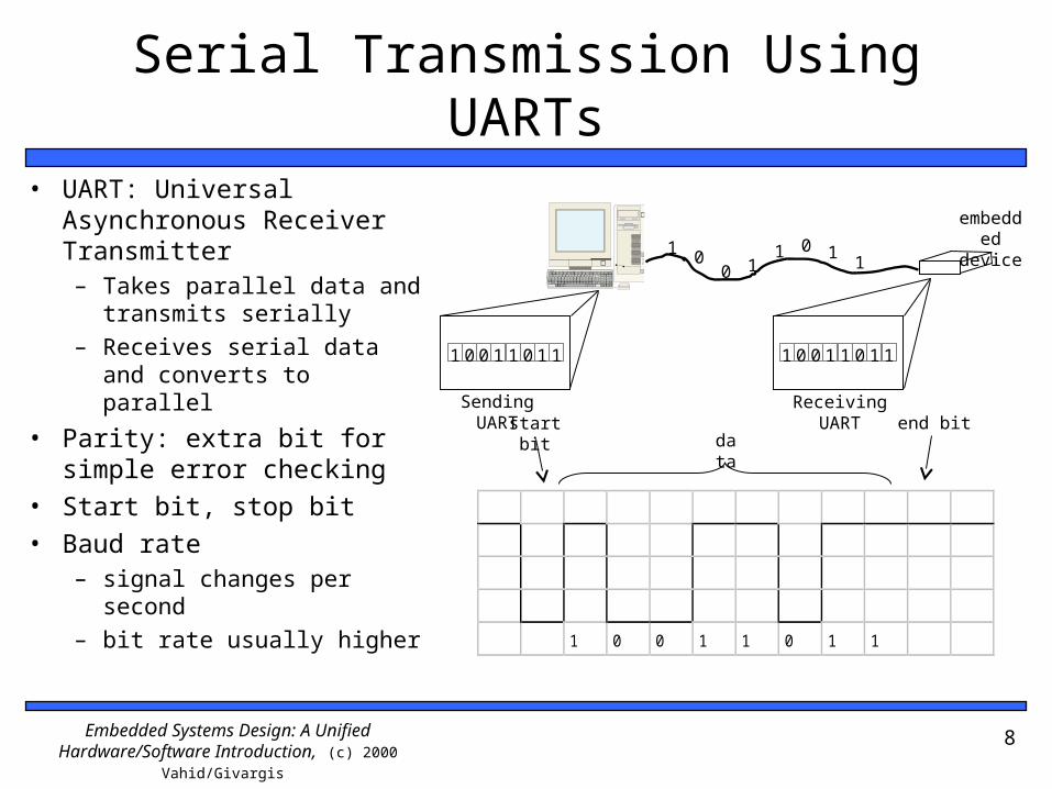
Serial Transmission Using UARTs
embedded device1 0
0 11 0 1
1
Sending UART
1 0 0 1 1 0 1 1
Receiving UART
1 0 0 1 1 0 1 1
start bitdata
end bit
1 0 0 1 1 0 1 1
• UART: Universal Asynchronous Receiver Transmitter– Takes parallel data and
transmits serially
– Receives serial data and converts to parallel
• Parity: extra bit for simple error checking
• Start bit, stop bit
• Baud rate– signal changes per second
– bit rate usually higher
Embedded Systems Design: A Unified Hardware/Software Introduction, (c) 2000 Vahid/Givargis
9
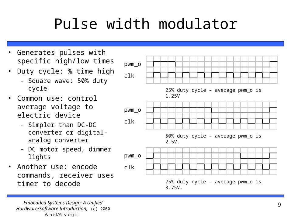
Pulse width modulator
clk
pwm_o
25% duty cycle – average pwm_o is 1.25V
clk
pwm_o
50% duty cycle – average pwm_o is 2.5V.
clk
pwm_o
75% duty cycle – average pwm_o is 3.75V.
• Generates pulses with specific high/low times
• Duty cycle: % time high– Square wave: 50% duty cycle
• Common use: control average voltage to electric device– Simpler than DC-DC
converter or digital-analog converter
– DC motor speed, dimmer lights
• Another use: encode commands, receiver uses timer to decode
Embedded Systems Design: A Unified Hardware/Software Introduction, (c) 2000 Vahid/Givargis
10
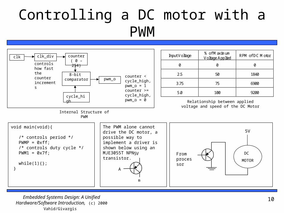
Controlling a DC motor with a PWM
void main(void){
/* controls period */ PWMP = 0xff; /* controls duty cycle */ PWM1 = 0x7f;
while(1){}; }
The PWM alone cannot drive the DC motor, a possible way to implement a driver is shown below using an MJE3055T NPN transistor.
5V
B
A
Internal Structure of PWM
clk_div
cycle_high
counter( 0 – 254)
8-bit comparator
controls how fast the counter increments counter <
cycle_high,pwm_o = 1counter >= cycle_high, pwm_o = 0
pwm_o
clk Input Voltage% of MaximumVoltage Applied
RPM of DC Motor
0 0 0
2.5 50 1840
3.75 75 6900
5.0 100 9200
Relationship between applied voltage and speed of the DC Motor
DC
MOTOR
5V
From processor
Embedded Systems Design: A Unified Hardware/Software Introduction, (c) 2000 Vahid/Givargis
11
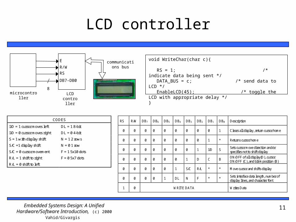
LCD controller
E
R/W
RS
DB7–DB0
LCD controller
communications bus
microcontroller8
void WriteChar(char c){
RS = 1; /* indicate data being sent */ DATA_BUS = c; /* send data to LCD */ EnableLCD(45); /* toggle the LCD with appropriate delay */}
CODES
I/D = 1 cursor moves left DL = 1 8-bit
I/D = 0 cursor moves right DL = 0 4-bit
S = 1 with display shift N = 1 2 rows
S/C =1 display shift N = 0 1 row
S/C = 0 cursor movement F = 1 5x10 dots
R/L = 1 shift to right F = 0 5x7 dots
R/L = 0 shift to left
RS R/W DB7 DB6 DB5 DB4 DB3 DB2 DB1 DB0 Description
0 0 0 0 0 0 0 0 0 1 Clears all display, return cursor home
0 0 0 0 0 0 0 0 1 * Returns cursor home
0 0 0 0 0 0 0 1 I/D SSets cursor move direction and/orspecifies not to shift display
0 0 0 0 0 0 1 D C BON/OFF of all display(D), cursorON/OFF (C), and blink position (B)
0 0 0 0 0 1 S/C R/L * * Move cursor and shifts display
0 0 0 0 1 DL N F * *Sets interface data length, number ofdisplay lines, and character font
1 0 WRITE DATA Writes Data
Embedded Systems Design: A Unified Hardware/Software Introduction, (c) 2000 Vahid/Givargis
12
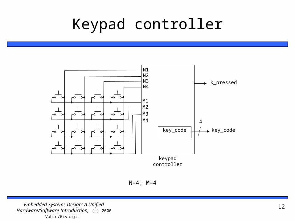
Keypad controller
N1N2N3N4
M1M2
M3M4
key_code
keypad controller
k_pressed
key_code
4
N=4, M=4
Embedded Systems Design: A Unified Hardware/Software Introduction, (c) 2000 Vahid/Givargis
13
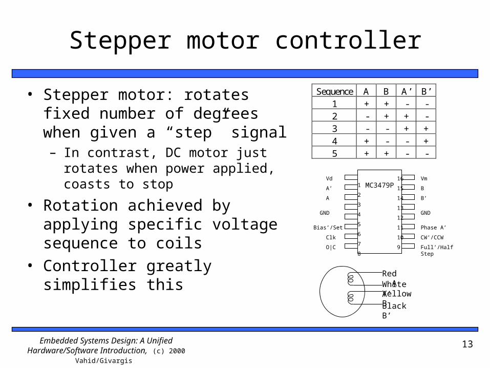
Stepper motor controller
Red AWhite A’Yellow B
Black B’
MC3479P 1
5
4
3
2
7
8
6
16
15
14
13
12
11
10
9
Vd
A’
A
GND
Bias’/Set
Clk
O|C
Vm
B
B’
GND
Phase A’
CW’/CCW
Full’/Half Step
Sequence A B A’ B’1 + + - -2 - + + -3 - - + +4 + - - +5 + + - -
• Stepper motor: rotates fixed number of degrees when given a “step” signal– In contrast, DC motor just rotates when
power applied, coasts to stop
• Rotation achieved by applying specific voltage sequence to coils
• Controller greatly simplifies this
Embedded Systems Design: A Unified Hardware/Software Introduction, (c) 2000 Vahid/Givargis
14
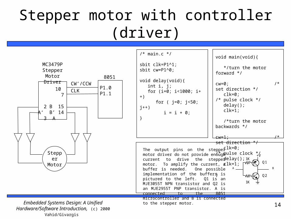
Stepper motor with controller (driver)
2 A’ 3 A
10 7
B 15B’ 14
MC3479PStepper Motor
Driver 8051
P1.0P1.1
StepperMotor
CLK
CW’/CCW
The output pins on the stepper motor driver do not provide enough current to drive the stepper motor. To amplify the current, a buffer is needed. One possible implementation of the buffers is pictured to the left. Q1 is an MJE3055T NPN transistor and Q2 is an MJE2955T PNP transistor. A is connected to the 8051 microcontroller and B is connected to the stepper motor.
Q2
1K
1KQ1
+V
A B
void main(void){
*/turn the motor forward */ cw=0; /* set direction */ clk=0; /* pulse clock */ delay(); clk=1;
/*turn the motor backwards */ cw=1; /* set direction */ clk=0; /* pulse clock */ delay(); clk=1;
}
/* main.c */
sbit clk=P1^1;sbit cw=P1^0;
void delay(void){ int i, j; for (i=0; i<1000; i++) for ( j=0; j<50; j++) i = i + 0;}
Embedded Systems Design: A Unified Hardware/Software Introduction, (c) 2000 Vahid/Givargis
15
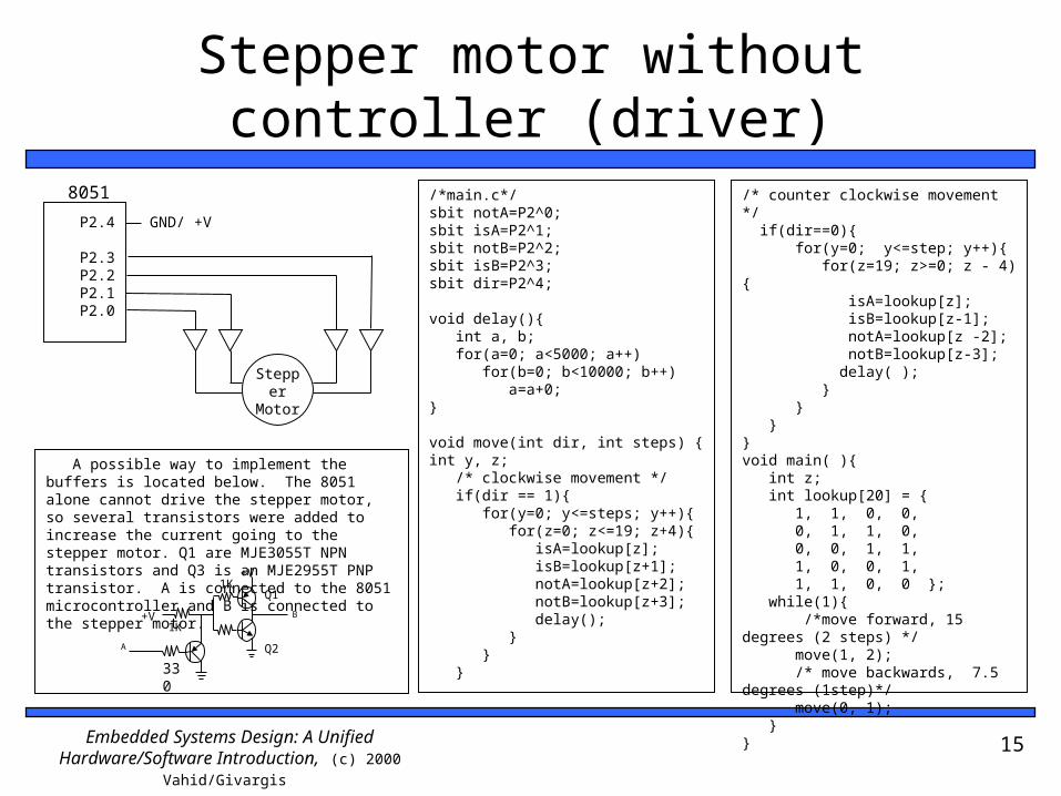
Stepper motor without controller (driver)
StepperMotor
8051
GND/ +VP2.4
P2.3P2.2P2.1P2.0
A possible way to implement the buffers is located below. The 8051 alone cannot drive the stepper motor, so several transistors were added to increase the current going to the stepper motor. Q1 are MJE3055T NPN transistors and Q3 is an MJE2955T PNP transistor. A is connected to the 8051 microcontroller and B is connected to the stepper motor.
Q2
+V
1KQ1
1K
+V
A
B
330
/*main.c*/sbit notA=P2^0;sbit isA=P2^1;sbit notB=P2^2;sbit isB=P2^3;sbit dir=P2^4;
void delay(){ int a, b; for(a=0; a<5000; a++) for(b=0; b<10000; b++) a=a+0;}
void move(int dir, int steps) {int y, z; /* clockwise movement */ if(dir == 1){ for(y=0; y<=steps; y++){ for(z=0; z<=19; z+4){ isA=lookup[z]; isB=lookup[z+1]; notA=lookup[z+2]; notB=lookup[z+3]; delay(); } } }
/* counter clockwise movement */ if(dir==0){ for(y=0; y<=step; y++){ for(z=19; z>=0; z - 4){ isA=lookup[z]; isB=lookup[z-1]; notA=lookup[z -2]; notB=lookup[z-3]; delay( ); } } }}void main( ){ int z; int lookup[20] = { 1, 1, 0, 0, 0, 1, 1, 0, 0, 0, 1, 1, 1, 0, 0, 1, 1, 1, 0, 0 }; while(1){ /*move forward, 15 degrees (2 steps) */ move(1, 2); /* move backwards, 7.5 degrees (1step)*/ move(0, 1); }}
Embedded Systems Design: A Unified Hardware/Software Introduction, (c) 2000 Vahid/Givargis
16
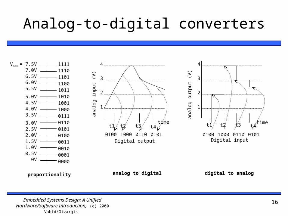
Analog-to-digital converters
proportionality
Vmax = 7.5V
0V
11111110
0000
0010
0100
0110
1000
1010
1100
0001
0011
0101
0111
1001
1011
1101
0.5V1.0V1.5V2.0V2.5V3.0V
3.5V4.0V4.5V5.0V
5.5V6.0V6.5V7.0V
analog to digital
4
3
2
1
t1 t2 t3 t4
0100 1000 0110 0101
time
anal
og in
put (
V)
Digital output
digital to analog
4
3
2
1
0100 1000 0110 0101
t1 t2 t3 t4time
anal
og o
utpu
t (V
)
Digital input
Embedded Systems Design: A Unified Hardware/Software Introduction, (c) 2000 Vahid/Givargis
17
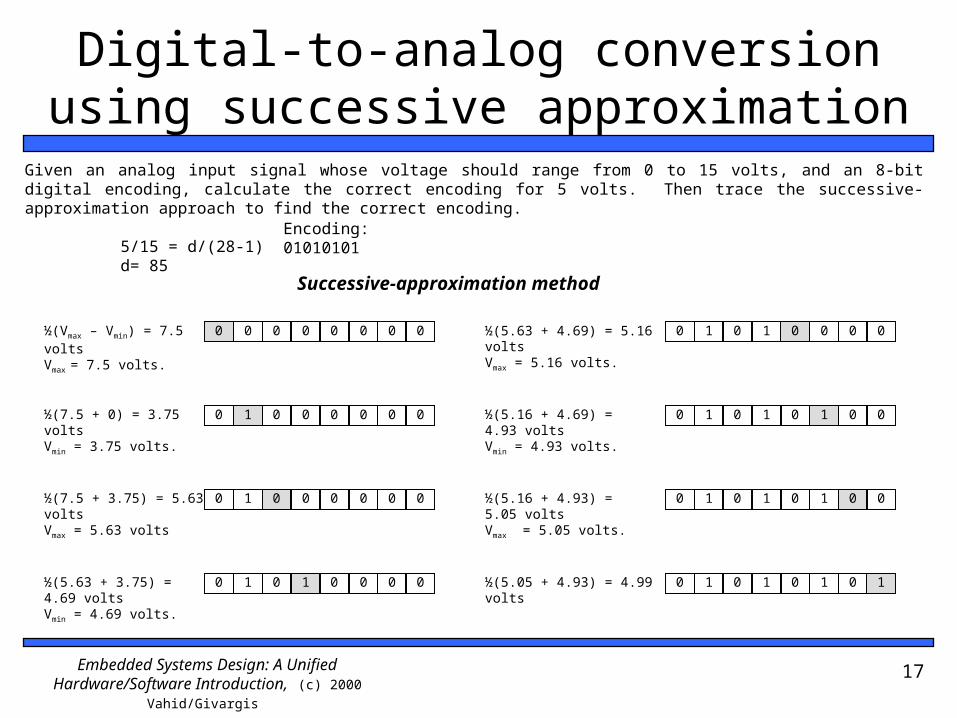
Given an analog input signal whose voltage should range from 0 to 15 volts, and an 8-bit digital encoding, calculate the correct encoding for 5 volts. Then trace the successive-approximation approach to find the correct encoding.
5/15 = d/(28-1)d= 85
Successive-approximation method
Digital-to-analog conversion using successive approximation
0 1 0 0 0 0 0 0
Encoding: 01010101
½(Vmax – Vmin) = 7.5 voltsVmax = 7.5 volts.
½(7.5 + 0) = 3.75 voltsVmin = 3.75 volts.
0 0 0 0 0 0 0 0
0 1 0 0 0 0 0 0½(7.5 + 3.75) = 5.63 voltsVmax = 5.63 volts
½(5.63 + 3.75) = 4.69 voltsVmin = 4.69 volts.
0 1 0 1 0 0 0 0
½(5.63 + 4.69) = 5.16 voltsVmax = 5.16 volts.
0 1 0 1 0 0 0 0
½(5.16 + 4.69) = 4.93 voltsVmin = 4.93 volts.
0 1 0 1 0 1 0 0
½(5.16 + 4.93) = 5.05 voltsVmax = 5.05 volts.
0 1 0 1 0 1 0 0
½(5.05 + 4.93) = 4.99 volts 0 1 0 1 0 1 0 1