Embed Size (px)
Citation preview
32
CHAPTER 3
PRELIMINARY DESIGN OF MICRO-SATELLITE
STRUCTURE
Structural design of a satellite is a complicated iterative process that
contains selection of configuration, materials, design, analysis and testing.
Structural design is dependent on the design requirements set by the other
subsystems like power, propulsion, communications and thermal. The design
process starts at a conceptual stage with design specifications which are based
on mission requirements. In general the specifications include the
accommodation of payload and subsystems, launch requirements,
environmental protection, thermal and electrical paths, good stiffness, mass
efficiency and high reliability. The structural design process also provides a
interface to each individual unit or equipment in order to aid the integration
sequence.
3.1 METHODS OF SATELLITE DESIGN
Today, three separate methods exist within the field of satellite
design. These practiced methodologies are:
Conventional subsystem by subsystem design, unique to each
mission.
Modular design for multiple missions.
Low cost/high risk design.
33
3.1.1 Conventional subsystem by subsystem design
Conventionally, satellites are designed uniquely for each mission.
After defining the requirements and constraints of the mission, each one of
the subsystems of the satellite namely power, propulsion, attitude
determination & control, thermal control, communications, command & data
handling, and the structure - are designed separately and iteratively. This
method of satellite design probably produces the most reliable spacecraft for a
particular mission but also makes the spacecraft most expensive.
3.1.2 Modular design for multiple missions
In the second methodology - modular designs for multiple missions
- the satellite subsystems are developed in the same manner as before.
However, the requirements on which the designs made are not for a single
unique mission, but for an anticipated range of missions. Thus, the
development costs are significantly reduced because each satellite is not
designed from the scratch. Each bus contains a nearly identical 1) modular
power system, 2) command & data handling module, 3) attitude determination
& control system, 4) modular structure, and 5) payload interface. Only the
payload instruments differ from mission to mission. The modular satellite
design provides the advantage of reducing the development costs at the
expense of not providing the most optimal design for a single given satellite
mission.
3.1.3 Small satellites with low cost/high risk design
“Small Sat Revolution” a new satellite design methodology
emerged to produce satellites with less production cost and with a high-risk
design. In addition to developing satellites weighing thousands of kilograms
and costing hundreds of millions of dollars, engineers began designing
"smallsats" weighing 200 kg or less and costing only a couple million dollars.
34
The size of these small satellites also reduces the operational costs. This
methodology asserts that launching of many small, less capable, high risks,
low cost satellites to perform a mission will in the long run prove cheaper
than launching a few large, highly capable, overly redundant, lower risks, and
a very high cost satellites.
Therefore on the positive side, smallsats are cheaper than the
conventional satellites and afford the space flight opportunities for groups that
would otherwise be unable to afford one aboard a conventional satellite. On
the negative side, smallsats cannot carry as many instruments as, they have a
shorter lifetime than, and are more susceptible to single point failures than
conventionally designed and sized satellites.
In the process of design and development of a micro-satellite
structure within the specified envelope and also to accommodate 40 numbers
of subsystems a wide collection of existing spacecraft configurations, mass,
mission and structural concepts data was analyzed and the commonalities
were identified. The idea behind this is to identify the most common type of
structure like central tube, truss, frame, equipment or instrument box,
equipment platform, solar array panel and antenna support structure that can
be used in the satellite for various missions, the advantages and disadvantages
of various structural elements.
3.2 PRIMARY STRUCTURAL DESIGN
Primary structures are designed using several criteria that depend
on the mission requirements. Conventional spacecraft incorporate 4 basic
primary structural designs:
1) Skin-frame structures
2) Truss structures
35
3) Monocoque cylinders
4) Skin-stringer structures
3.2.1 Skin-frame structures
The skin-frame structural design uses an interior skeletal networkof axial and lateral frames to mount exterior skin panels using fasteners or
rivets. The frames support bending, torsion, and axial forces. The skinreinforces the structure by supporting the shear forces introduced by the
interior member connections. The skin is sometimes minimized to save mass,even though the thin skin leads to some structural instability. When the skin
buckles due to shear, it transfers all additional shear loads to in-plane tensionforces at 45° which must be supported by the connections. The buckling
modes of the skin exhibit large deformations that make it insufficient forexterior mounted components such as solar cells. The buckling strength of the
assembly is typically increased by adding intermediate members.
3.2.2 Truss structures
Truss structures use an array of members that can only support the
axial loads. Truss members are produced independently and arrangedtypically in an array of triangles for stability. The members are manufactured
using extruded tubes made of composite, metallic, or sheet metal materials. Astable truss is statically determinate and has no excess members to introduce
the alternate load paths. Trusses are generally mass efficient when themembers are configured into rectangular or triangular cross-sectional
assemblies. However, they become less efficient as the cross-section becomesmore circular or hexagonal. Also, the design of the structure creates an
inherent stress concentration at the interface mounting points, such asseparation systems. Components may be mounted both internally and
externally and the absence of shear panels enables easy access to a payload.
36
However, this absence of shear panels is not helpful to spacecraft requiringbody mounted solar cells.
3.2.3 Monocoque cylinders
Monocoque cylinders are axisymmetric shells that do not contain
any stiffeners or frames. The shells are manufactured by using metallic or
sandwich panels with curved sections formed by rolling. Typically, two or
three curved sections are fabricated and assembled into the cylindrical
configuration. The strength of monocoque cylinders is usually limited by its
buckling strength. The shells are most efficient when the loads are distributed
evenly throughout the structure. Components are typically mounted to the
walls using fasteners; however care must be taken not to overload the shell
and cause local failures. The monocoque cylinder design is applicable to
spacecraft with body mounted solar cells and relatively lightweight
components.
3.2.4 Skin-stringer structures
Cylindrical skin-stringer structures are designed using axial and
lateral frame members attached to an outer skin. These designs are similar to
skin-frame structures; however, this class of structures refers to circular
cylinder configurations. The skin is sometimes minimized to save mass, even
though the thin skin leads to some structural instability. The Post-buckling
behavior of the skin transfers the additionally applied shear loads to torsion by
the diagonal tension phenomenon described above. The skin and members
must attach uniformly to enable the assembly to act as a continuous structure.
Typical connection methods include fasteners and/or rivets. Interior
components are usually mounted to the walls at locations along the stringer
assembly. This method is more efficient than monocoque cylinder component
mounting at introducing local loads. The skin must be designed sufficiently
37
stiff to enable sound mounting of exterior entities such as body mounted solar
cells.
The absence of shear panels in truss structures cannot be used for
body mounted solar panels. The monocoque cylinder structure is difficult to
assemble and integrate as it is generally made of two or three curved sections
and components are mounted on the wall as it does not contain stringers or
frames. The interior components in the skin-stringer structure are usually
mounted to the walls at locations along the stringer assembly and hence
difficult to mount more number of components. As the skin-frame structures
use interior skeletal network of axial and lateral frames to mount exterior skin
panels using fasteners which is further used to fix the body mounted solar
panels. The axial and lateral skin-frame structures are used to accommodate
more number of subsystems than any other structures.
3.3 CONVENTIONAL SATELLITE STRUCTURES
3.3.1 Sandwich Structures
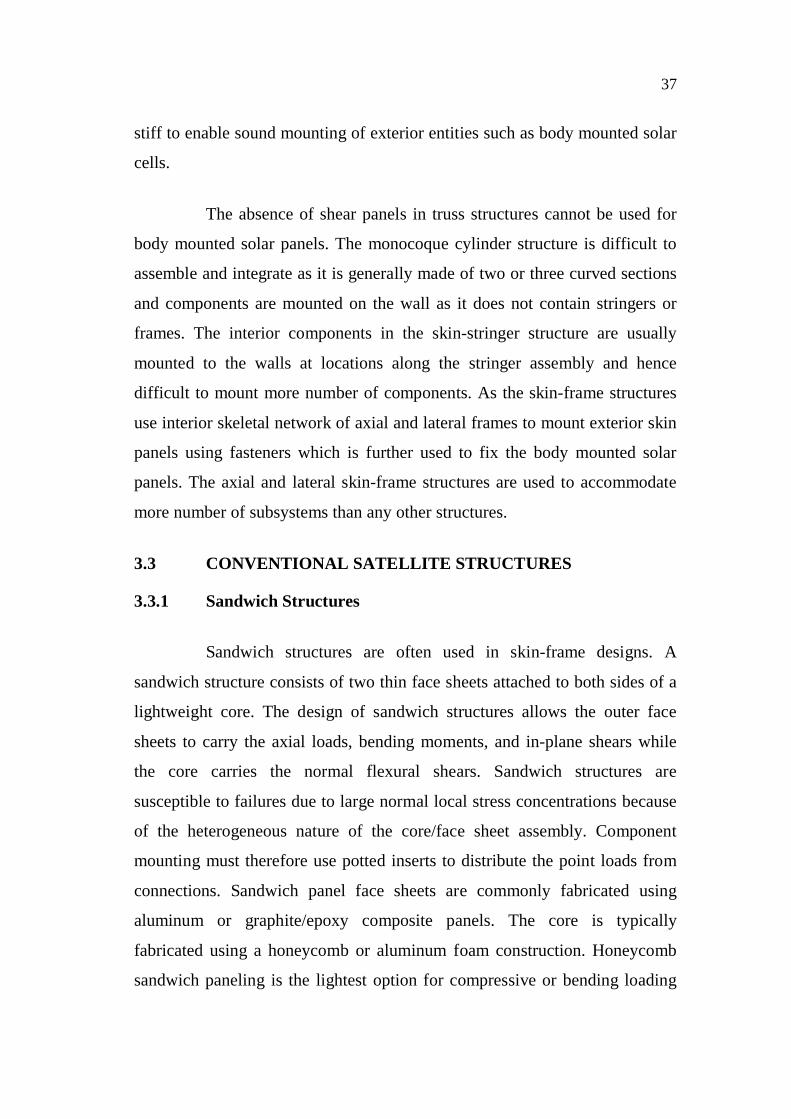
Sandwich structures are often used in skin-frame designs. A
sandwich structure consists of two thin face sheets attached to both sides of a
lightweight core. The design of sandwich structures allows the outer face
sheets to carry the axial loads, bending moments, and in-plane shears while
the core carries the normal flexural shears. Sandwich structures are
susceptible to failures due to large normal local stress concentrations because
of the heterogeneous nature of the core/face sheet assembly. Component
mounting must therefore use potted inserts to distribute the point loads from
connections. Sandwich panel face sheets are commonly fabricated using
aluminum or graphite/epoxy composite panels. The core is typically
fabricated using a honeycomb or aluminum foam construction. Honeycomb
sandwich paneling is the lightest option for compressive or bending loading
38
specific applications. Honeycomb sandwich cores are manufactured using
thin strips formed into honeycomb cells. The honeycomb geometry is non-
isotropic with greater stiffness in the longitudinal direction. However, the core
acts nearly isotropically for in-plane loads when assembled in a sandwich
configuration. The disadvantages of using honeycomb cores are the potted
inserts required for mounting and the thermal inefficiencies. These
inefficiencies stem from the low thermal conductivity of the adhesive layers
used in construction and make use of honeycomb prohibitive in optical and
mirror aerospace application.
Figure 3.1 Sandwich panel
3.3.2 Multifunctional Structures
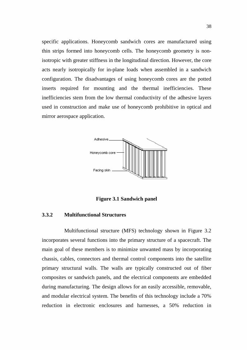
Multifunctional structure (MFS) technology shown in Figure 3.2
incorporates several functions into the primary structure of a spacecraft. The
main goal of these members is to minimize unwanted mass by incorporating
chassis, cables, connectors and thermal control components into the satellite
primary structural walls. The walls are typically constructed out of fiber
composites or sandwich panels, and the electrical components are embedded
during manufacturing. The design allows for an easily accessible, removable,
and modular electrical system. The benefits of this technology include a 70%
reduction in electronic enclosures and harnesses, a 50% reduction in
39
spacecraft volume required for these conventional components, a reduction in
labor required for spacecraft assembly and an extremely robust system with
wide applicability to several missions.
Figure 3.2 Multi functional structural panels with integral electronic,
structural and thermal control
3.3.3 Isogrid Structures
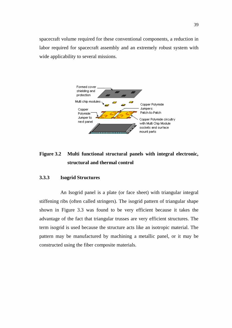
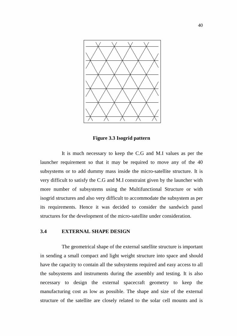
An Isogrid panel is a plate (or face sheet) with triangular integral
stiffening ribs (often called stringers). The isogrid pattern of triangular shape
shown in Figure 3.3 was found to be very efficient because it takes the
advantage of the fact that triangular trusses are very efficient structures. The
term isogrid is used because the structure acts like an isotropic material. The
pattern may be manufactured by machining a metallic panel, or it may be
constructed using the fiber composite materials.
40
Figure 3.3 Isogrid pattern
It is much necessary to keep the C.G and M.I values as per the
launcher requirement so that it may be required to move any of the 40
subsystems or to add dummy mass inside the micro-satellite structure. It is
very difficult to satisfy the C.G and M.I constraint given by the launcher with
more number of subsystems using the Multifunctional Structure or with
isogrid structures and also very difficult to accommodate the subsystem as per
its requirements. Hence it was decided to consider the sandwich panel
structures for the development of the micro-satellite under consideration.
3.4 EXTERNAL SHAPE DESIGN
The geometrical shape of the external satellite structure is important
in sending a small compact and light weight structure into space and should
have the capacity to contain all the subsystems required and easy access to all
the subsystems and instruments during the assembly and testing. It is also
necessary to design the external spacecraft geometry to keep the
manufacturing cost as low as possible. The shape and size of the external
structure of the satellite are closely related to the solar cell mounts and is
41
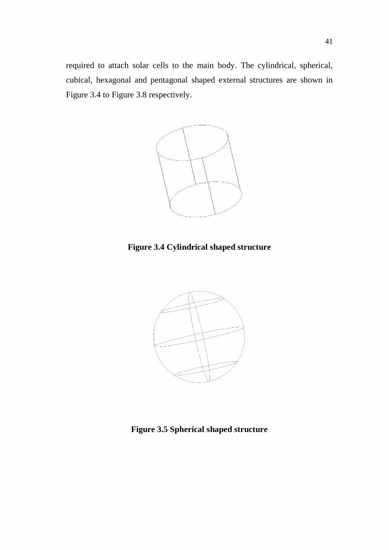
required to attach solar cells to the main body. The cylindrical, spherical,
cubical, hexagonal and pentagonal shaped external structures are shown in
Figure 3.4 to Figure 3.8 respectively.
Figure 3.4 Cylindrical shaped structure
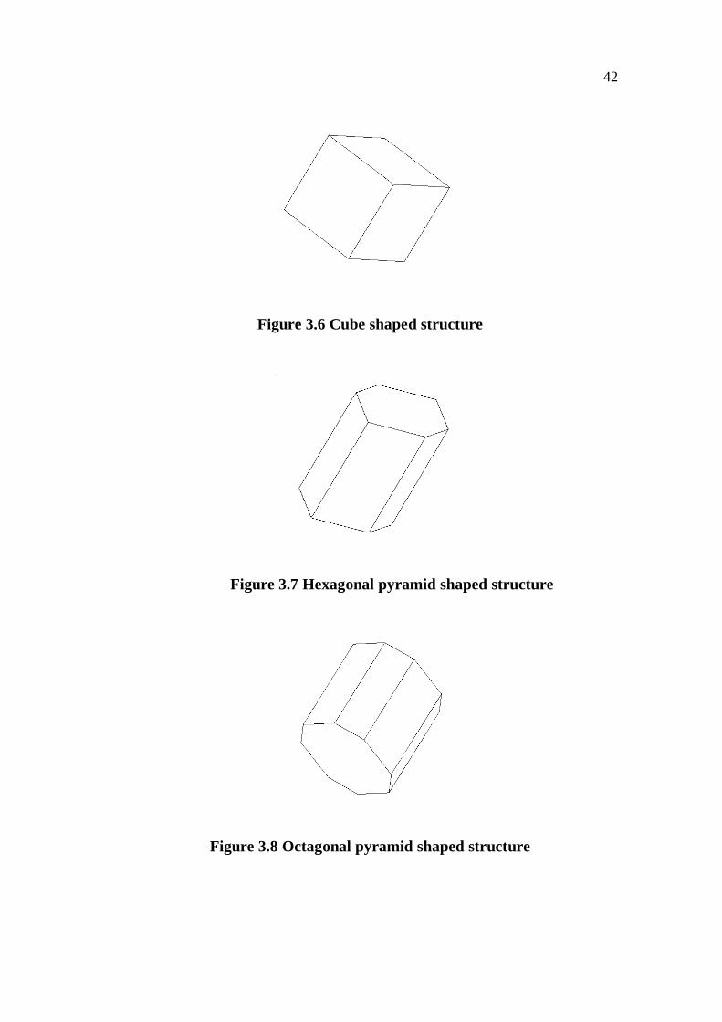
Figure 3.5 Spherical shaped structure
42
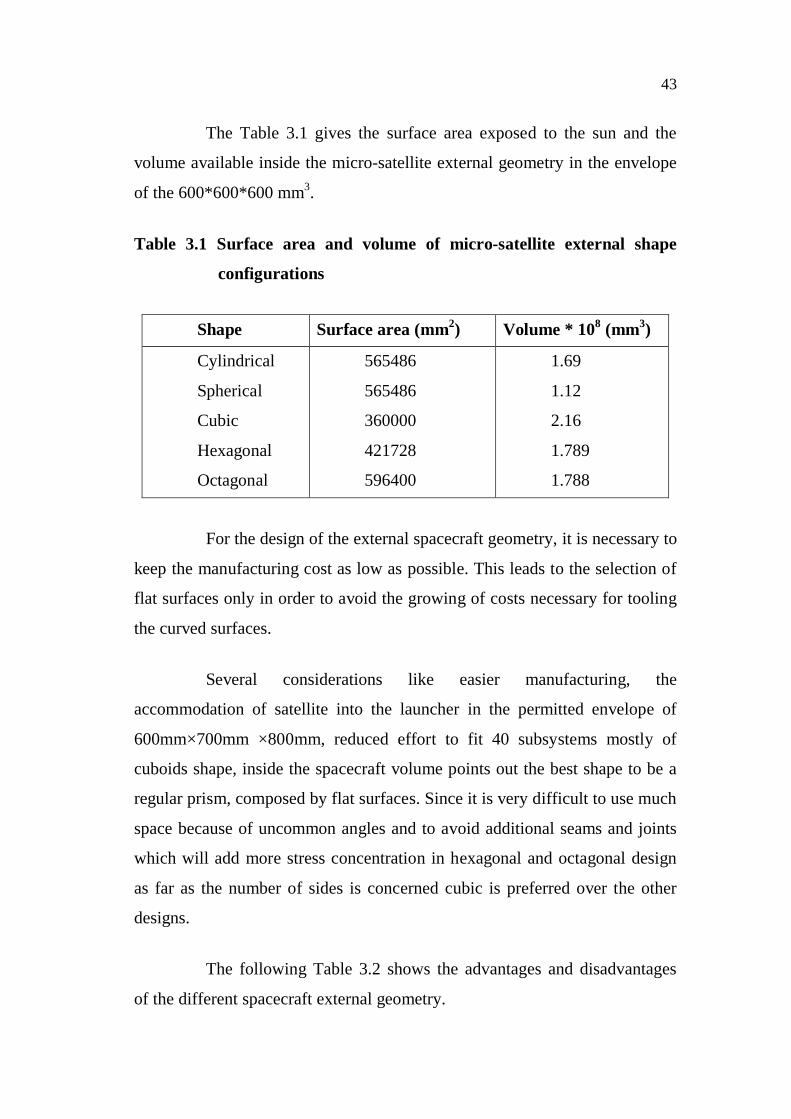
Figure 3.6 Cube shaped structure
Figure 3.7 Hexagonal pyramid shaped structure
Figure 3.8 Octagonal pyramid shaped structure
43
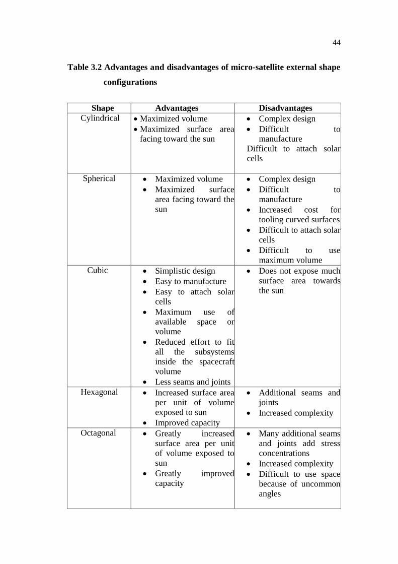
The Table 3.1 gives the surface area exposed to the sun and the
volume available inside the micro-satellite external geometry in the envelope
of the 600*600*600 mm3.
Table 3.1 Surface area and volume of micro-satellite external shape
configurations
Shape Surface area (mm2) Volume * 108 (mm3)
Cylindrical
Spherical
Cubic
Hexagonal
Octagonal
565486
565486
360000
421728
596400
1.69
1.12
2.16
1.789
1.788
For the design of the external spacecraft geometry, it is necessary to
keep the manufacturing cost as low as possible. This leads to the selection of
flat surfaces only in order to avoid the growing of costs necessary for tooling
the curved surfaces.
Several considerations like easier manufacturing, the
accommodation of satellite into the launcher in the permitted envelope of
600mm×700mm ×800mm, reduced effort to fit 40 subsystems mostly of
cuboids shape, inside the spacecraft volume points out the best shape to be a
regular prism, composed by flat surfaces. Since it is very difficult to use much
space because of uncommon angles and to avoid additional seams and joints
which will add more stress concentration in hexagonal and octagonal design
as far as the number of sides is concerned cubic is preferred over the other
designs.
The following Table 3.2 shows the advantages and disadvantages
of the different spacecraft external geometry.
44
Table 3.2 Advantages and disadvantages of micro-satellite external shape
configurations
Shape Advantages DisadvantagesCylindrical Maximized volume
Maximized surface areafacing toward the sun
Complex designDifficult tomanufacture
Difficult to attach solarcells
Spherical Maximized volumeMaximized surfacearea facing toward thesun
Complex designDifficult tomanufactureIncreased cost fortooling curved surfacesDifficult to attach solarcellsDifficult to usemaximum volume
Cubic Simplistic designEasy to manufactureEasy to attach solarcellsMaximum use ofavailable space orvolumeReduced effort to fitall the subsystemsinside the spacecraftvolumeLess seams and joints
Does not expose muchsurface area towardsthe sun
Hexagonal Increased surface areaper unit of volumeexposed to sunImproved capacity
Additional seams andjointsIncreased complexity
Octagonal Greatly increasedsurface area per unitof volume exposed tosunGreatly improvedcapacity
Many additional seamsand joints add stressconcentrationsIncreased complexityDifficult to use spacebecause of uncommonangles
45
3.5 SOLAR PANEL MOUNTING
The solar cell mounts are closely related to the shape and size of the
structure. Deployable solar panels would be required if the body mounted
solar cells are inadequate to generate power to perform the satellites mission
while staying within the maximum dimensions of the launch vehicle. Both
body mounted and deployable solar panels have been considered on need
basis.
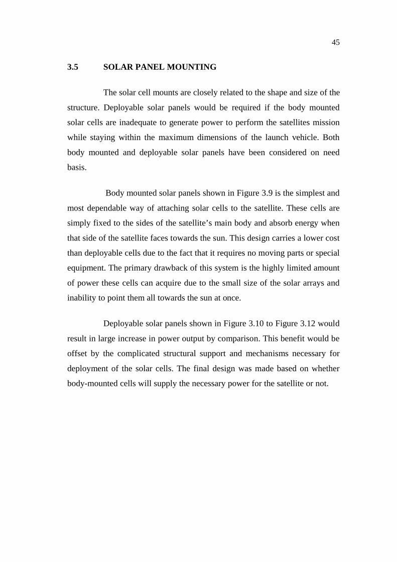
Body mounted solar panels shown in Figure 3.9 is the simplest and
most dependable way of attaching solar cells to the satellite. These cells are
simply fixed to the sides of the satellite’s main body and absorb energy when
that side of the satellite faces towards the sun. This design carries a lower cost
than deployable cells due to the fact that it requires no moving parts or special
equipment. The primary drawback of this system is the highly limited amount
of power these cells can acquire due to the small size of the solar arrays and
inability to point them all towards the sun at once.
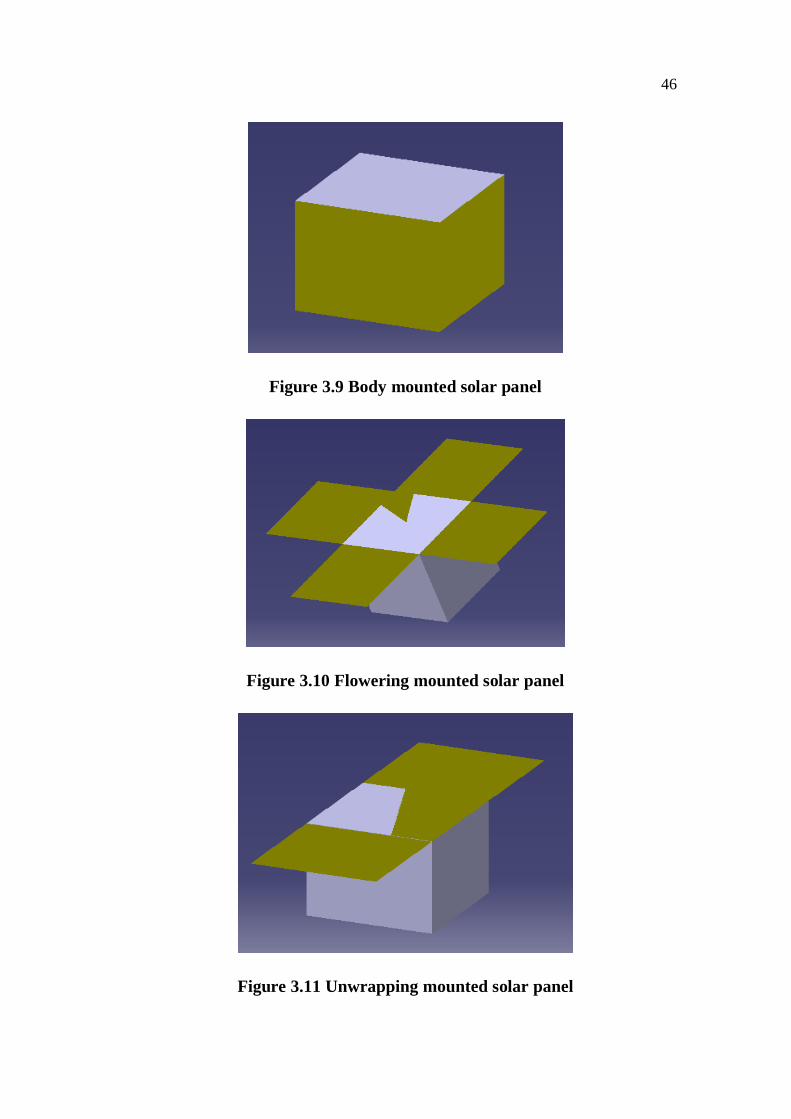
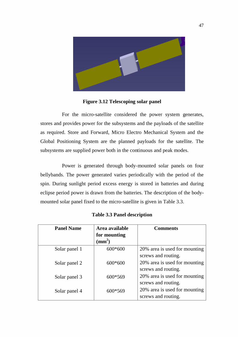
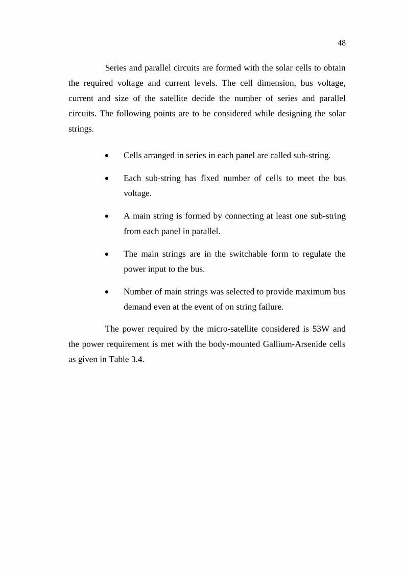
Deployable solar panels shown in Figure 3.10 to Figure 3.12 would
result in large increase in power output by comparison. This benefit would be
offset by the complicated structural support and mechanisms necessary for
deployment of the solar cells. The final design was made based on whether
body-mounted cells will supply the necessary power for the satellite or not.
46
Figure 3.9 Body mounted solar panel
Figure 3.10 Flowering mounted solar panel
Figure 3.11 Unwrapping mounted solar panel
47
Figure 3.12 Telescoping solar panel
For the micro-satellite considered the power system generates,
stores and provides power for the subsystems and the payloads of the satellite
as required. Store and Forward, Micro Electro Mechanical System and the
Global Positioning System are the planned payloads for the satellite. The
subsystems are supplied power both in the continuous and peak modes.
Power is generated through body-mounted solar panels on four
bellybands. The power generated varies periodically with the period of the
spin. During sunlight period excess energy is stored in batteries and during
eclipse period power is drawn from the batteries. The description of the body-
mounted solar panel fixed to the micro-satellite is given in Table 3.3.
Table 3.3 Panel description
Panel Name Area availablefor mounting(mm2)
Comments
Solar panel 1
Solar panel 2
Solar panel 3
Solar panel 4
600*600
600*600
600*569
600*569
20% area is used for mountingscrews and routing.20% area is used for mountingscrews and routing.20% area is used for mountingscrews and routing.20% area is used for mountingscrews and routing.
48
Series and parallel circuits are formed with the solar cells to obtain
the required voltage and current levels. The cell dimension, bus voltage,
current and size of the satellite decide the number of series and parallel
circuits. The following points are to be considered while designing the solar
strings.
Cells arranged in series in each panel are called sub-string.
Each sub-string has fixed number of cells to meet the bus
voltage.
A main string is formed by connecting at least one sub-string
from each panel in parallel.
The main strings are in the switchable form to regulate the
power input to the bus.
Number of main strings was selected to provide maximum bus
demand even at the event of on string failure.
The power required by the micro-satellite considered is 53W and
the power requirement is met with the body-mounted Gallium-Arsenide cells
as given in Table 3.4.
49
Table 3.4 Solar cell-String comparison
Cell description Silicon cells Gallium-Arsenide cells
Size of cell 20mm*40mm 20mm*40mm
Number of cells persub-string
39 23
Power per cell(W) 0.125 0.2
Voltage per cell(V) 0.45 0.78
% area occupied by onesub-string
10% 6%
Average power of onemain string (W)
4 4
Number of main stringspossible
8 14
Total power (W) 32 56
3.6 INTERNAL STRUCTURAL CONFIGURATION
The internal mounting faces serve two purposes: i) as mounting
surfaces for various components and ii) as additional structural support for the
spacecraft. A strong internal structure is desirable which is normally achieved
at the cost of additional mass. Four concepts were considered for the internal
mounts as given in Table 3.5
Table 3.5 Summary of internal structure configuration
Concepts Advantages DisadvantagesPlatform Improved lateral support No added vertical
supportCrossed Improved lateral and
vertical supportLoss of usable space
Trunk Much improved lateraland vertical support
Higher mass
Open Very low mass Loss of symmetry
50
Even though the crossed internal structural configuration adds mass
and loss of usable space still it is better to accommodate more number of
subsystems within their requirements, improved lateral and vertical support
compared to other configurations and easy achievable of C.G and M.I values
according to launcher requirements. For selecting a suitable crossed internal
structural configuration a preliminary free vibration analysis was made for
some 11 possible options without subsystems. The shape, the mass and the
natural frequency for the first three modes of all the possible options are given
below.
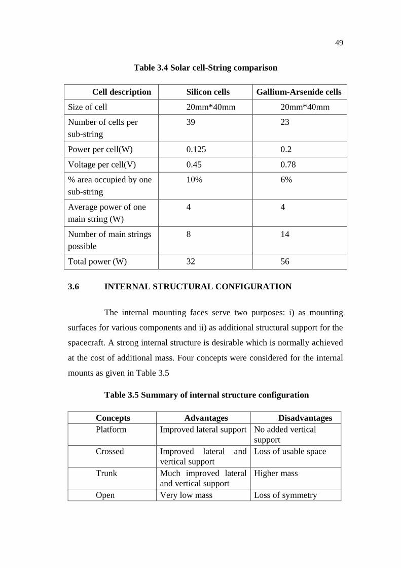
3.6.1 Option 1
Full-length vertical cross webs between the top deck and the
bottom deck with a height of 600mm between them as in Figure 3.13.
Figure 3.13 Configuration 1
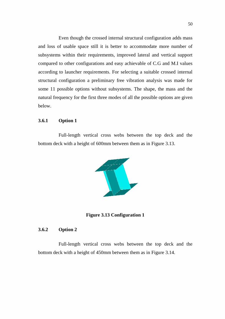
3.6.2 Option 2
Full-length vertical cross webs between the top deck and the
bottom deck with a height of 450mm between them as in Figure 3.14.
51
Figure 3.14 Configuration 2
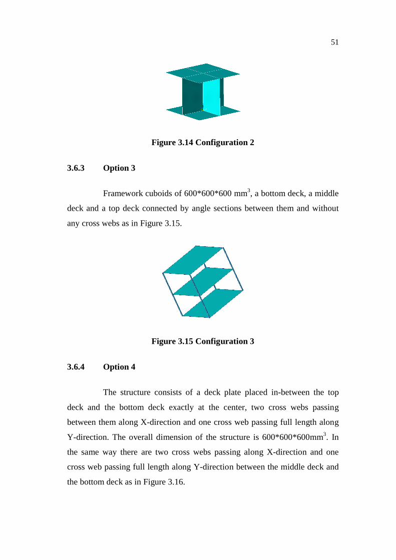
3.6.3 Option 3
Framework cuboids of 600*600*600 mm3, a bottom deck, a middle
deck and a top deck connected by angle sections between them and without
any cross webs as in Figure 3.15.
Figure 3.15 Configuration 3
3.6.4 Option 4
The structure consists of a deck plate placed in-between the top
deck and the bottom deck exactly at the center, two cross webs passing
between them along X-direction and one cross web passing full length along
Y-direction. The overall dimension of the structure is 600*600*600mm3. In
the same way there are two cross webs passing along X-direction and one
cross web passing full length along Y-direction between the middle deck and
the bottom deck as in Figure 3.16.
52
Figure 3.16 Configuration 4
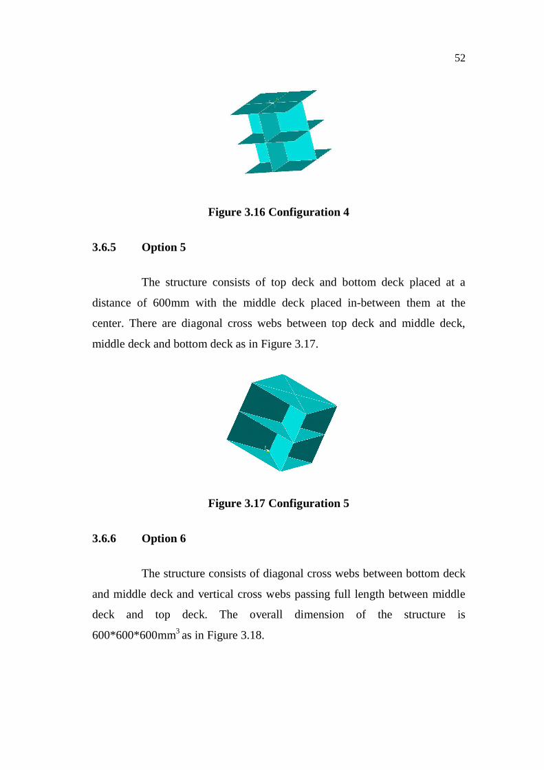
3.6.5 Option 5
The structure consists of top deck and bottom deck placed at a
distance of 600mm with the middle deck placed in-between them at the
center. There are diagonal cross webs between top deck and middle deck,
middle deck and bottom deck as in Figure 3.17.
Figure 3.17 Configuration 5
3.6.6 Option 6
The structure consists of diagonal cross webs between bottom deck
and middle deck and vertical cross webs passing full length between middle
deck and top deck. The overall dimension of the structure is
600*600*600mm3 as in Figure 3.18.
53
Figure 3.18 Configuration 6
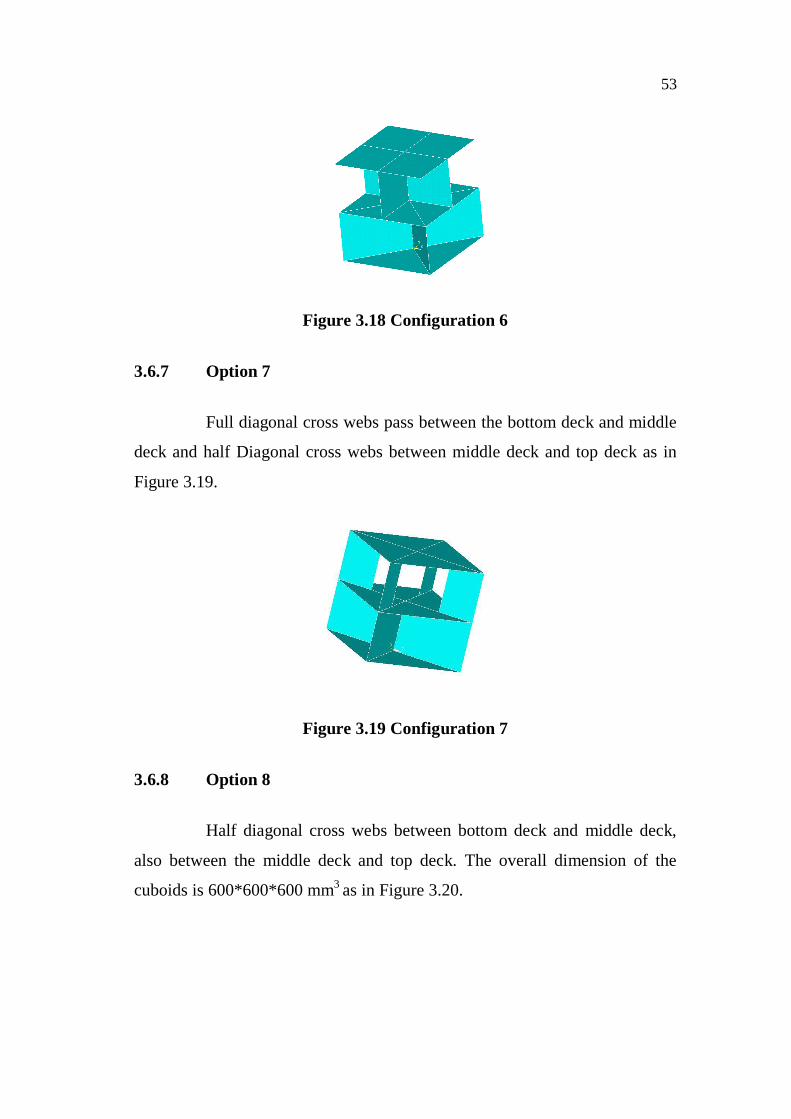
3.6.7 Option 7
Full diagonal cross webs pass between the bottom deck and middle
deck and half Diagonal cross webs between middle deck and top deck as in
Figure 3.19.
Figure 3.19 Configuration 7
3.6.8 Option 8
Half diagonal cross webs between bottom deck and middle deck,
also between the middle deck and top deck. The overall dimension of the
cuboids is 600*600*600 mm3 as in Figure 3.20.
54
Figure 3.20 Configuration 8
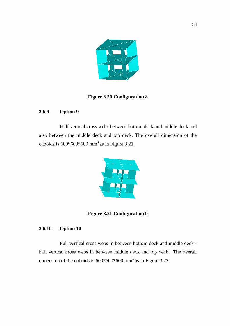
3.6.9 Option 9
Half vertical cross webs between bottom deck and middle deck and
also between the middle deck and top deck. The overall dimension of the
cuboids is 600*600*600 mm3 as in Figure 3.21.
Figure 3.21 Configuration 9
3.6.10 Option 10
Full vertical cross webs in between bottom deck and middle deck -
half vertical cross webs in between middle deck and top deck. The overall
dimension of the cuboids is 600*600*600 mm3 as in Figure 3.22.
55
Figure 3.22 Configuration 10
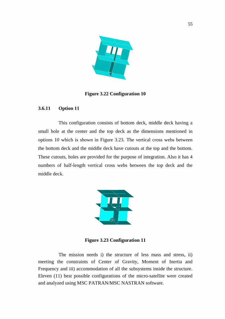
3.6.11 Option 11
This configuration consists of bottom deck, middle deck having a
small hole at the center and the top deck as the dimensions mentioned in
options 10 which is shown in Figure 3.23. The vertical cross webs between
the bottom deck and the middle deck have cutouts at the top and the bottom.
These cutouts, holes are provided for the purpose of integration. Also it has 4
numbers of half-length vertical cross webs between the top deck and the
middle deck.
Figure 3.23 Configuration 11
The mission needs i) the structure of less mass and stress, ii)meeting the constraints of Center of Gravity, Moment of Inertia andFrequency and iii) accommodation of all the subsystems inside the structure.Eleven (11) best possible configurations of the micro-satellite were createdand analyzed using MSC PATRAN/MSC NASTRAN software.
56
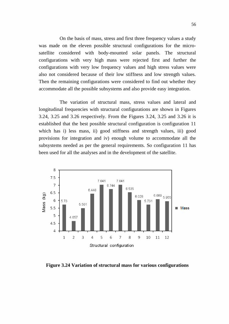
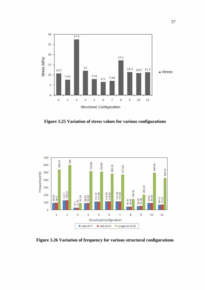
On the basis of mass, stress and first three frequency values a studywas made on the eleven possible structural configurations for the micro-satellite considered with body-mounted solar panels. The structuralconfigurations with very high mass were rejected first and further theconfigurations with very low frequency values and high stress values werealso not considered because of their low stiffness and low strength values.Then the remaining configurations were considered to find out whether theyaccommodate all the possible subsystems and also provide easy integration.
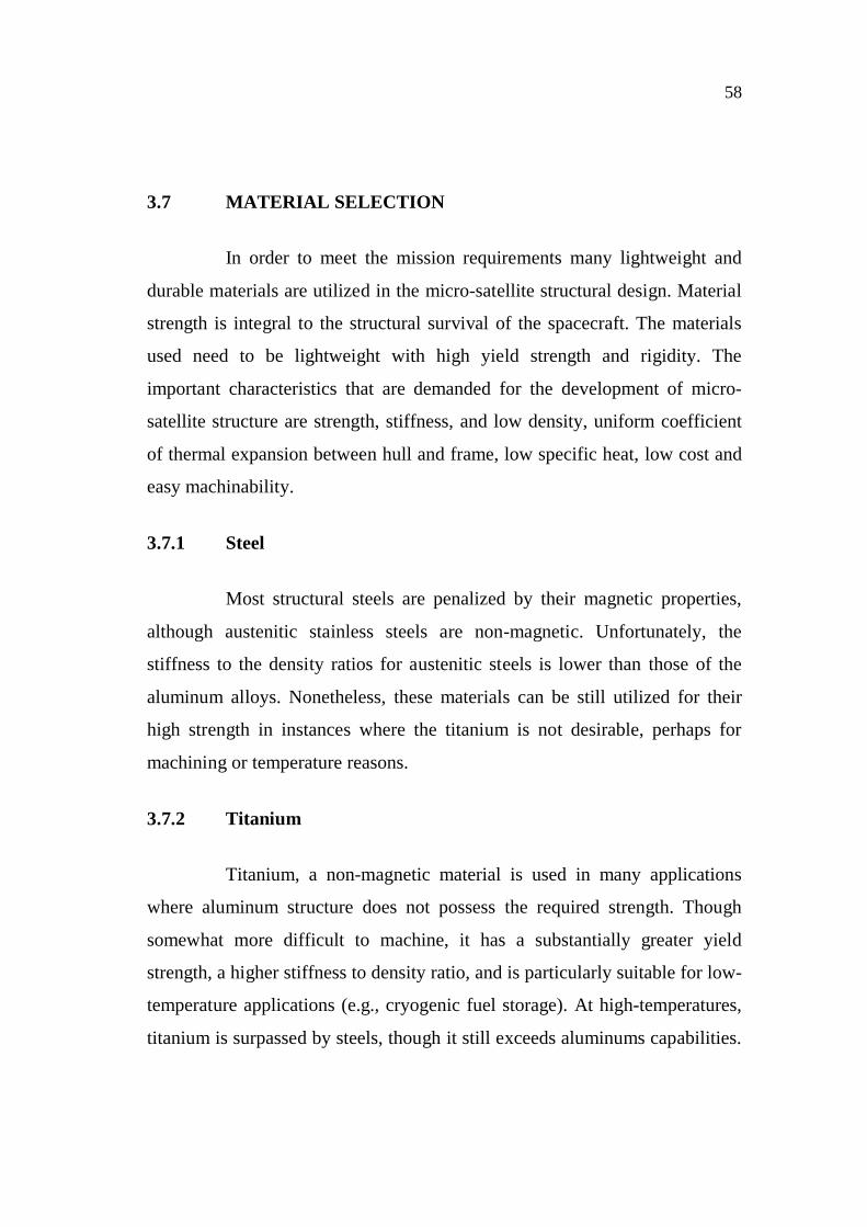
The variation of structural mass, stress values and lateral andlongitudinal frequencies with structural configurations are shown in Figures3.24, 3.25 and 3.26 respectively. From the Figures 3.24, 3.25 and 3.26 it isestablished that the best possible structural configuration is configuration 11which has i) less mass, ii) good stiffness and strength values, iii) goodprovisions for integration and iv) enough volume to accommodate all thesubsystems needed as per the general requirements. So configuration 11 hasbeen used for all the analyses and in the development of the satellite.
Figure 3.24 Variation of structural mass for various configurations
57
Figure 3.25 Variation of stress values for various configurations
Figure 3.26 Variation of frequency for various structural configurations
58
3.7 MATERIAL SELECTION
In order to meet the mission requirements many lightweight and
durable materials are utilized in the micro-satellite structural design. Material
strength is integral to the structural survival of the spacecraft. The materials
used need to be lightweight with high yield strength and rigidity. The
important characteristics that are demanded for the development of micro-
satellite structure are strength, stiffness, and low density, uniform coefficient
of thermal expansion between hull and frame, low specific heat, low cost and
easy machinability.
3.7.1 Steel
Most structural steels are penalized by their magnetic properties,
although austenitic stainless steels are non-magnetic. Unfortunately, the
stiffness to the density ratios for austenitic steels is lower than those of the
aluminum alloys. Nonetheless, these materials can be still utilized for their
high strength in instances where the titanium is not desirable, perhaps for
machining or temperature reasons.
3.7.2 Titanium
Titanium, a non-magnetic material is used in many applications
where aluminum structure does not possess the required strength. Though
somewhat more difficult to machine, it has a substantially greater yield
strength, a higher stiffness to density ratio, and is particularly suitable for low-
temperature applications (e.g., cryogenic fuel storage). At high-temperatures,
titanium is surpassed by steels, though it still exceeds aluminums capabilities.
59
Research may greatly increase the ease of manufacturing complex titanium
components.
A relatively new class of titanium based materials is the
intermetallic titanium alumides, or tialuminides. These low density materials
exhibit high strength at temperatures greater than 700° C and resist oxidation
at all temperatures. Primary uses are as a composite matrix material and in
honeycomb structures. Unfortunately, tialuminides react poorly with
hydrogen and become brittle. This limits their utility in vehicles that use
hydrogen to actively cool the airframe unless protective coatings are used.
3.7.3 Magnesium
Though its stiffness to density ratio is close to aluminum, this
material and its alloys are prone to brittle fracture. This reduces its
applications to those where its barely higher yield strength may be of some
use, or where its good low-temperature behavior is paramount. As already
mentioned, magnesium sublimes relatively quickly in vacuum (0.04 in/yr at
180° C). Exposure to temperatures less than 250° C can cause it to lose static
strength, although electroplating or coatings can prevent this.
3.7.4 Beryllium
With a density approximately 60% of aluminum and a stiffness to
weight ratio six times better than aluminum or titanium, this material has
many potential applications. Being stiffer than other materials it can be useful
in avoiding resonant frequencies that may occur between a satellite and its
booster during launch. It is non-magnetic, has a high elastic modulus and high
yield strength. Using beryllium instead of aluminum can reduce weight
significantly, and its high thermal conductivity makes it an excellent choice
for components that will conduct heat. It is also non-reactive with hydrogen.
60
However, beryllium is extremely anisotropic and sensitive to
damage, and is twice as brittle as aluminum. Its relatively low fracture
toughness at cryogenic temperatures is a potential drawback, but development
of beryllium-aluminum alloys may improve this. It also needs special
facilities and tools for machining due to the toxicity of its dust, and is thus
very expensive.
3.7.5 Composites
Composite materials are quickly becoming the material of choice
for aerospace applications. They possess stiffness to weight ratios beyond all
metals, making them useful for damping unwanted vibrations. With a
negative axial coefficient of thermal expansion, they allow for structures that
will not deform in the temperature extremes of space. Their thermal
conductivity exceeds copper, and so they also provide lightweight thermal
management and heat sinks. Where stiffness is critical, as in telescopes,
antennas, and reflectors, carbon fiber composites are another natural choice.
Metal matrix, Carbon-Carbon, and Ceramic-Matrix composites are
best for high temperature applications, such as re-entry vehicle skins, since
they can withstand temperatures in excess of 2500° F with no active cooling.
However, there are some drawbacks to these materials. Effective oxidation
coatings must be developed, as well as manufacturing techniques for a large
scale structures. Grounding of electrical systems is done by adding conductive
strips, which increase the mass of the structure. Nicks and dents that can be
repaired or ignored in structural metals can destroy the integrity of the fibers
and render the composite unusable. In space, with little or no inspection and
maintenance, and where failure of primary structure can have devastating
consequences, composites are typically judged too unreliable for use as more
than secondary structure. But judicious use of composites in secondary
structure can still result in much mass savings. Another concern of laminated
61
composites is their reaction to temperature changes. Uniform changes can
induce substantial internal stresses caused by different expansion rates
between the fibers and matrix. Temperature differentials can produce more
pronounced warping than in an isotropic material.
Composite materials also have been considered but it does not
appear to be a suitable solution because of the frequent changes in the
structure (due to iterative design process), which is not compatible with
composites technology.
3.7.6 Aluminum
A combination of high stiffness to density ratio, excellent
workability, non-magnetism, moderate cost, high ductility, high corrosion-
resistance, and availability in numerous forms makes aluminium the best
choice for micro-satellite considered. Its low yield strength is the only
appreciable disadvantage. Hence the material used for the micro-satellite is
considered as aluminium in the form of rods, plates and honeycomb panels.
Honeycomb aluminium is used for flat panels due to its extremely low density
in comparison to the aluminium plate of the same strength. The subsystems
are manufactured by shop machining process starting from the aluminium
block by which the unnecessary material is removed.