Embed Size (px)
Citation preview
CHAPTER 3
LEAKAGE REACTANCE CALCULATIONS
3.1 Introduction
In Chapter 2, while considering the fundamental
energy conversion process in a L~I, the attention was
necessarily focussed on the active region of the machine.
Inevitably, even in the idealised theoretical model, there
exist some leakage fields that link either the stator or
rotor circuits only. The leakage reactances assume
importance when the applied voltage and power factor
characteristics of the current-fed machine are examined,
or when the machine is run from a constant-voltage source.
There has not been any significant contribution in this
as~ect of LIMs except the paper by Allin et al30 in which
the leakage reactances of a laboratory LIM model is experi-
mentally obtained. It is probable that questions regarding
the leakage reactances were pushed into the background as
the emphasis in LIM research so far has all along been on
the current-fed mode of operation10 ,22-24. In addition,
exhaustive work had been previously done on the leakage
reactances of different types of conventional round rotor
induction motors (Alger, P.L. 31 ), and it is qUite possible
that some of the formulae could be modified and used for
38
the LIMs. Yet it is considered desirable to explore the
possibility of developing analytical expressions for the
leakage reactances of LIMs keeping the geometry of the
machine more or less intact for the following reasons:
1. The stator winding overhang leakage reactance of
the longitudinal-flux LIM is relatively large on account
of the larger pole pitch as shown by Laithwaite1 ,3.
2. A topological cylindrical equivalent of the double
sided LIM does not exist conceptually, since only the outer
surface of the round rotor is available for induction.
3. It is recognised that the sheet secondary constru
ction of the LIM facilitates a simplified field theoretic
formulation of the leakage reactance problem.
The elements of leakage reactance that are generally
taken into consideration for a conventional induction motor
can be broadly classified as 31
1. Primary winding overhang leakage reactance
2. Primary slot leakage reactance
3. Secondary leakage reactance
4. Air-gap leakage reactance
Some of the physical features characterising the
round rotor induction motor and giving rise to the above
leakage paths are not present in the type of linear
induction motors studied in this investigation.
39
Specifically, the aluminium sheet rotor construction
results in a low secondary leakage reactance even for
thick plates as shown by Laithwaite 1 • Analogous to the
terminology of conventional induction motors, the airgap
leakage reactance is brought about by the differential,
zig-zag and peripheral leakage fluxes. Again the unslotted
sheet rotor configuration permits ampere-turn balance of
the primary currents in the opposite gap surface at every
point, thereby eliminating the differential fluxes. For
the same reason, the zig-zag leakage fluxes also vanish
almost entirely.
It may be noted that in the previous chapter the
performance of the linear induction motor is predicted by
solving for the vector potential along the stator surface
so that the airgap leakage flux is automatically included
in the analysis of the active region. Consequently the
important components of the leakage flux that have to be,
separately accounted for are the coil end-turn leakage and
the primary slot leakage fields 25 •
3.2 Stator Overhang Leakage Reactance
In general, the coil end configuration of the stator
overhang region along with the geometry of the end ring
assembly gives rise to a complicated three-dimensional
pattern of end leakage flux that is very difficult to
determine exactly. One redeeming feature, however, is the
40
truely leakage nature of the overhang flux so that it can
be treated independent of the main field. In fact, as
Alger31 has pointed out, the calculation can be made as
if the stator core were removed and the winding projections
on either side brought together with the flux paths
entirely in air. Hence for the sake of analysis it is
assumed that the overhang field is unaffected by the
active ,region and rotor currents. This implies that the
longitudinal end effects and transverse edge effects of
the rotor can be neglected, affording a simplified treat-
mente
Alger31 has shown that for a double layer winding
with diamond shaped coils, the overhang currents can be
resolved into the axial (z) and peripheral (x) components,
which obey sinusoidel variation in both x and z directions.
A three-dimensional solution for the leakage field is
obtained by representing the winding overhang by a thin
continuous current sheet on either side of the stator
core level with the stator-airgap interface. Also, in
the following analysis, only the space fundamental of the
stator current distribution is considered, while the field
quantities have sinusoidal time variation at supply
frequency ~ as in eqn. 2.6.~
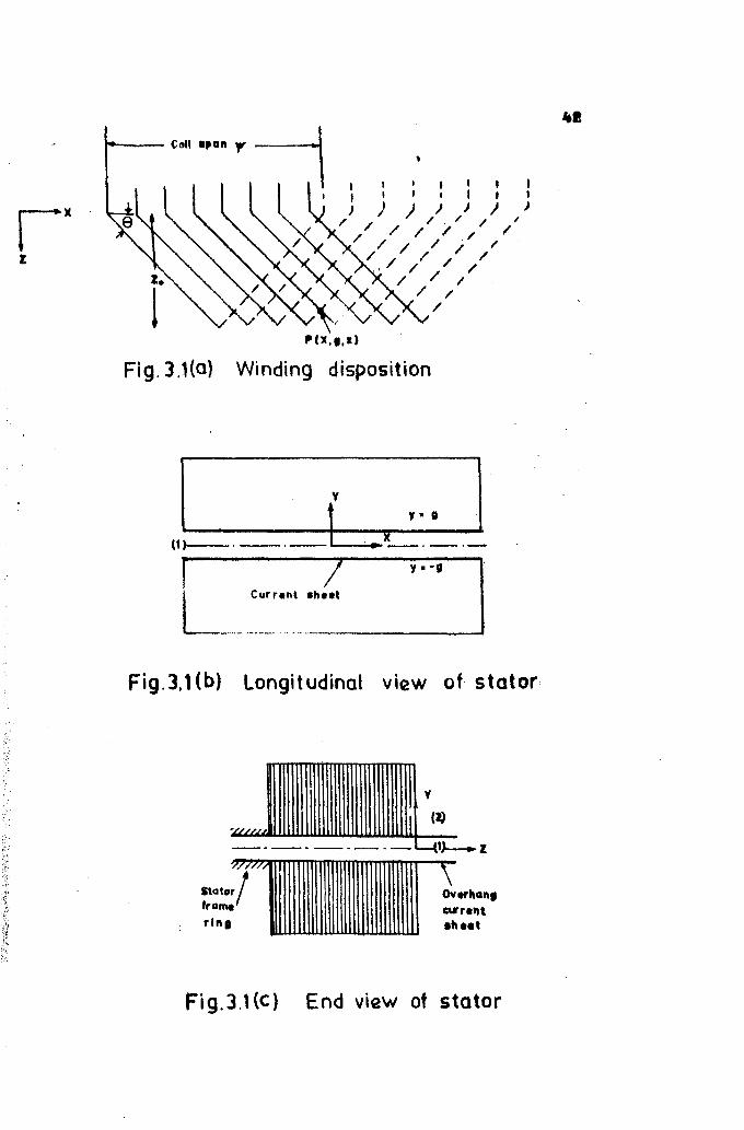
Referring to fig. 3.1 which shows the winding dis-
position along with the co-ordinate axes, the fundamental
41
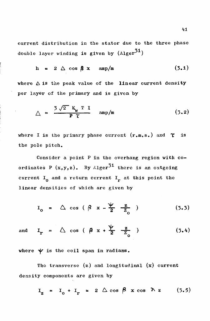
current distribution in the stator due to the three phase
double layer winding is given by (Alger31 )
h = 2 6. cos ~ x amp/m
where ~ is the peak value of the linear current density
per layer of the primary and is given by
6. =3j2~T1
P lamp/m
where I is the primary phase current (r.m.s.) and .~ is
the pole pitch.
Consider a point P in the overhang region with co
ordinates P (x,y,z). By Alger31 there is an outgoing
current 10
and a return current 1r at this point the
linear densities of which are given by
10 6 ( ~
'¥ z )= cos x -2' Zo
and I 6 cos ( p x + 't.. z )= --rr 20
where i' is the coil span in radians.
The transverse (z) and longitudinal (x) current
density components are given by
= = 2 6. cos f3 x cos 1\ z
I II I
) / ))J))/ / / / / '
/ .//// // / / / /
/ / / / /, // / / /
/ //
P(lI".I)
Fig.3.1(a) Winding disposition
y
y. I
X(1)1---' --.-- '--.;..,~;;....--. - .-
Fig.3.1 (b) Longitudinal view of stator
y
I;'.'.,',
StatorI'ramerln.
(),/erhan.CU"ren\.h ••,
Fig.3.Hc) End view of stator
43
and Ix = (I -I) cote = 2 ~ sin ~ x sin "Z cote (3.6)o r
and e is the angle of bend of the end"'V2Zo
turn measured from the positive x direction as in fig. 3.1(a).
where
The approach for determining the overhang leakage
reactances25 is essentially to solve for the field distri-
bution generated by the transverse and longitudinal compon-
ents of the end turn currents by formulation of the appro-
priate boundary value problems. Expressions for the leakage
reactive power flow are derived SUbsequently in terms of
the Poynting vector.
Due to certain constructional details of the disc
drive, discussed in Chapter 4, the two sides of the over-
hang on either side of the stator core are to be treated
slightly differently. vlliile the overhang at the outer
periphery of the (curved) stator block is placed entirely
in air, that at the inner side has an iron backing ring
which is part of the stator frame assembly holding the
laminations together. Also for each overhang current
sheet there are two regions of field propagation25 • In
the following, the airgap region between the stators LS
denoted by (1) and the back air region by (2).
The field equations in the regions (1) and (2) for
the outer overhang in the absence of rotor currents are
= 0
+ = 0, o<y < CX)
44
along y = 0, by symmetry about the xz plane
and = + along y =g
considering only the transverse component at the moment,
with I z given by eqn. 3.5.
The general solution of eqn. 3.7 for region (1)
consistent with eqn. 3.5 is given by
AZ1 (x,y,z) = Ai (y) cos ~ x cos1\ z
Substitution of AZ1 in eqn. 3.7 results in the
ordinary differential equation
= 0
where 11 2 =
45
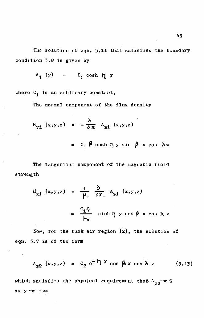
The solution o~ eqne 3.11 that satisfies the boundary
condition 3.8 is given by
:: C1 cosh " Y
where C1 is an arbitrary constant.
The normal component of the flux density
BY1 (x,y,z)a
:: - bx AZi (x,y,z)
:: C1 (6- cosh "l y sin p x cos AZ
The tangential component of the magnetic field
strength
HX1 (x,y,z) = 1-""0
o-oY AZ1 (x,y,z)
Cit)= - sinh'" Y cos f! X COB 1\ ZtJ.
Now, for the back air region (2), the solution of
eqn. 3.7 is of the form
AZ2 (x,y,z) = C2 e- t'\ y cos is x cos A Z
which satisfies the physical requirement that AZ2~ 0
as y ... + 00
46
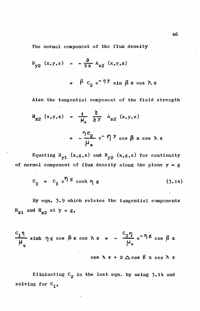
The normal component of the flux density
BY2
(x,y,z)o= - ~ AZ2 (x,y,Z)
= (3 C2
e - IJ y sin ft x cos A. z
Also the tangential component of the field strength
HX2 (x,y,z) 1= -~o
AZ2 (x,y,z)
I') 02= - - e- '1 y cos f3 x cos ~ zfJo
Equating By1 (x,g,z) and BY2 (x,g,z) for continuity
of normal component of flux density along the plane y = g
= C1 e1) g cosh ~ g
By eqn. 3.9 which relates the tangential components
HX1 and HX2 at y = g,
C1 ~- sinh t'l g cos (!> x cos 1\ z =
tJ o
cos ?\ z + 2 A cos f3 x cos A Z
Eliminating C2 in the last eqn. by using 3.14 and
solving for C1 ,
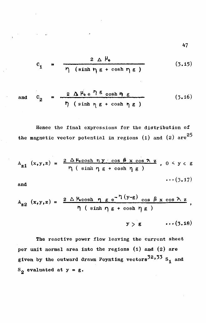
47
2 A Po=
t') (sinh t') g + cosh') g )
and =2 A f!~ e ''1 g cosh ~ g
t') (s inh ~ g + cosh r') g )
Hence the final expressions for the distribution of
the magnetic vector potential in regions (1) and (2) are25
AZ1 (x,y,z) =
and
2 A J.Locosh !} Y , cos ~ x cos 1\ z
~ ( sinh 1 g + cosh ~ g )O<'y< g
AZ2 (x,y,z) = 2 A J.l.cosh r') g e- '1 (y-g) cos ~ x cos A z
~ ( sinh ~ g + cosh ~ g )
y> g
The reactive power flow leaving the current sheet
per unit normal area into the regions (1) and (2) are
given by the outward drawn Poynting vectors32 ,33 81 and
82 evaluated at y =g.
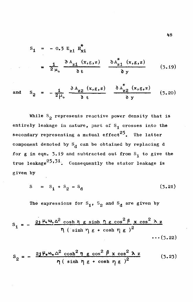
-48
*51 = - 0.5 EZ1 HX1
() AZ1 (x,g,z) * (x,g,z)1 e>Az1(3.19)= 2 1-40 ~t ay
aAZ2 (x,g,z) * (x,g,z)1 ~ A Z2 (J. 20)and 52 = - 2po "b t ~ Y
While 8 2 represents reactive power density that is
entirely leakage in nature, part of 51 crosses into the
secondary representing a mutual effect25 • The latter
component denoted by 5d can be obtained by replacing d
for g in eqn. 3.19 and subtracted out from 51 to give the
true leakage25,31~ Consequently the stator leakage is
given by
s = (3.21)
The expressions for 51' 52 and 5d are given by
2j t-t>oU)o~2 cosh II g sinh '1 g cos2 ~ x cos 21\ z
~ ( sinh ~ g + cosh ~ g )2
···(3.22)
2J V.~oD,.2 cosb2 1] g cos2 fl x cos2 i\ z
., ( sinh 1] g + cosh II g )2
49
~ { sinh ~ g + cosh ~ g )2
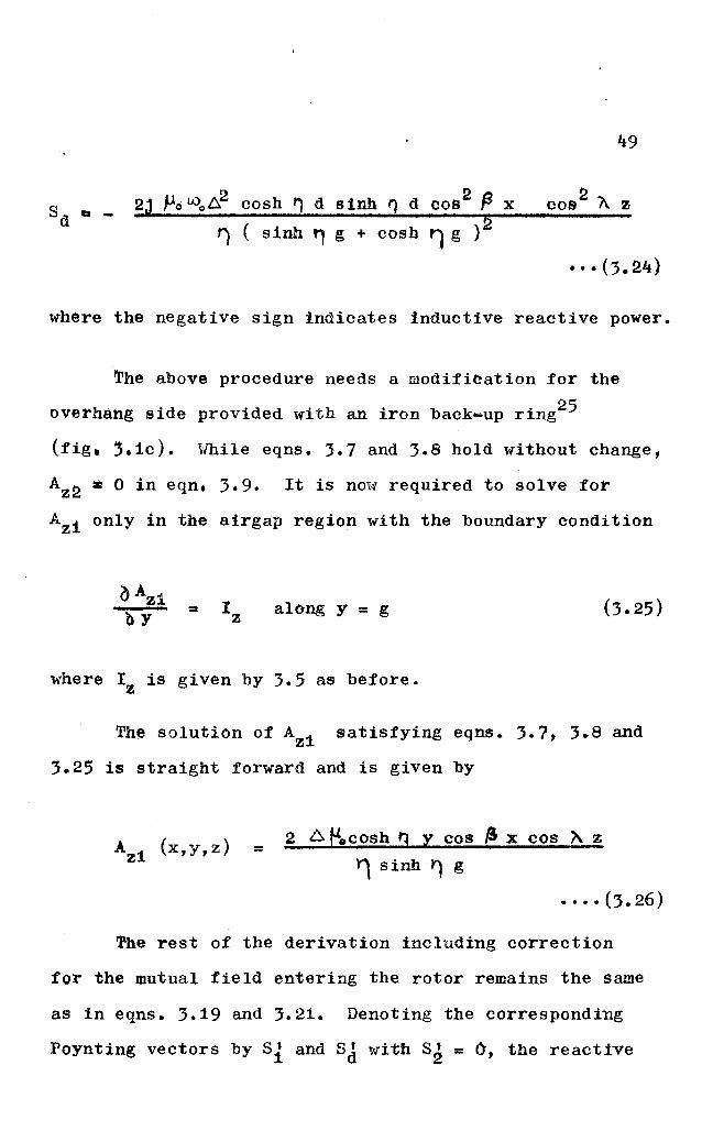
where the negative sign indicates inductive reactive power.
~he above procedure needs a modification for the
overhang side provided with an iron back-up ring25
(fig, ~.1c). \lliile eqns. 3.7 and 3.8 hold without change,
AZ2 * 0 in eqn. 3.9. It is now required to solve for
Az1 only in the airgap region with the boundary condition
= along y = g
where I z is given by 3.5 as before.
The solution of Az1 satisfying eqns. 3.7, 3.8 and
3.25 is straight forward and is given by
AZ1 (x,y,z) = 2 6 eocOsh t] y cos " x cos " z1 sinh Y) g
•••• (3.26)
The rest of the derivation including correction
for the mutual field entering the rotor remains the same
as in eqns. 3.19 and 3.21. Denoting the corresponding
Poynting vectors by Si and SJ with S~ = 0, the reactive
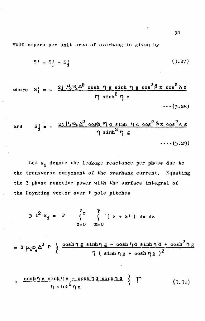
50
volt-ampere per unit area of overhang is given by
8' =8' - 8 I1 d
where 81. = - 2j tJ.o~oa2 cosh rt g sinh '1 g cos 2 tsx cos 2 l\z
~ sinh2 '1 g
···(3.28)
and 8 f ~ _ ,gj fJo(.l.)o ~ cosh 11 d sinh tl d cos 2 lex cos2~ z
d r, Sinh2 '1 g
Let xi denote the leakage reactance per phase due to
the transverse component of the overhang current. Equating
the 3 phase reactive power with the surface integral of
the Poynting vector over P pole pitches
3 12 x = P1
Z "r~ 0 ~'( 8 + 8' ) dx dz
z=o x=o
~ cosh!J g sinh., g - cosh!) d sinh" d + c.o~h2 '1 ~
( ., ( sinh t'1 g + cosh yt g ) 2
+cosh'1 g sinh ~ g - cosh., d sinh'1" ~ f'
'1 Sinh2 ') g ~
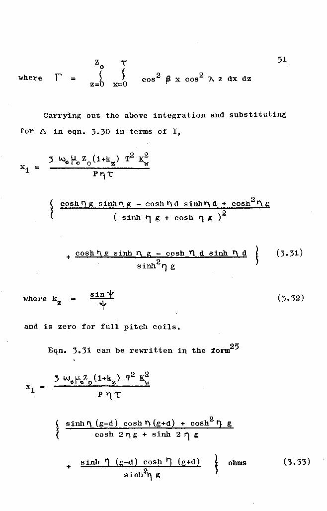
where T' =z l'
o ~
z=~ x=o
51
Carrying out the above integration and substituting
for 6, in eqn. 3.30 in terms of I,
3 l.\)oP'cZo(1+kz) T2
K;
P'11:'
~ cosh!) g sinh" g - cosh., d sinhr'\ d + cosh2Y') g
{ ( sinh ~ g + cosh ~ g )2
+ cosh!\ g sinh !') g - cosh!) d sinh !' d ~"002 ~S1 '1 g
where k z = sinX
t
and is zero for full pitch coils.
Eqn. 3.31 can be rewritten in the form25
3 woP'oozo (1+kz ) T2
K;
Py\T
~ sinh r'\ (g-d) cosh ,,(g+d) + cOSh2 'J g
{ cosh 2'1 g + sinh 2 " g
+sinh ~ (g-d) cosh 1 (g+d)
Sinh~ g
ohms
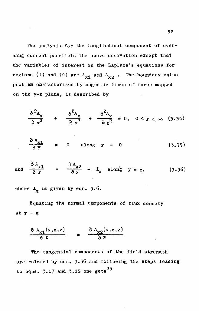
52
The analysis for the longitudinal component of over-
hang current parallels the above derivation except that
the variables of interest in the Laplace's equations for
regions (1) and (2) are AX1 and Ax2 • The boundary value
problem characterised by magnetic lines of force mapped
on the y-z plane, is described by
+ + = 0, o < y < 00 (3.34)
~Ax10 along 0 (3.35)CY = y =
andOAx1 oAX2
Ix• (3.36)
~ y = bY along Y = g,
where Ix is given by eqn. 3.6.
Equating the normal components of flux density
at y = g
a Ax1 (X,g,z)
o Z =
The tangential components of the field strength
are related by eqn. 3.36 and following the steps leading
to eqns. 3.17 and 3.18 one gets25
Ax1 {x,y,z) =
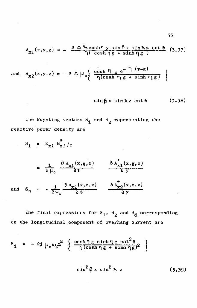
53
2 A ~ cosh '1 y s in ~ x sin" z cot e (3. 37)')( cosh '1g + sinh')g )
and l c~sh ~ g e- ~ (y-g)AX2 {x,y,z) = - 2 A U
1"0 If (cosh 1) g + sinh Y) g )
sin ~x sin 1\ z cot 9
The Poynting vectors 81 and 82 representing the
reactive power density are
*81 = Ex1 Hz1 / 2
a AX1 (x,g, z) *1 ~ AX1 (x,g,z)
= 2 t-Lo at oy
() AX2 (x, g, z) *and 8
21 ()Ax2 (x,g,z)
= - 2 f-lo at ay
The final expressions for 81 , 82 and 8d corresponding
to the longitudinal component of overhang current are
=
2. 2
- J U w Af'"'o 0 .
2 21 cosh Y) g cot e{ ~ (cosh r')g + Sinh'1g )2
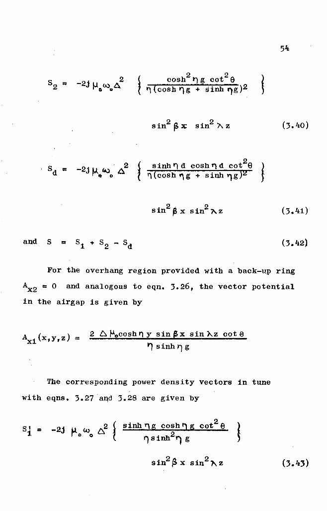
I S =d. 2 ~
-2j Mt;t.Qo A t sinh t') d cosh f) d cot2e ~'1 (cosh W'\ g + sinh 'l g )2 ~
2 . 2sin ~ x sin A,Z
and S =
For the overhang region provided with a back-up ring
AX2 = 0 and analogous to eqn. 3.26, the vector potential
in the airgap is given by
AX1 (X,y,Z) = 2 6. f-iocosh '1 y sin @:x sin~z cot er'} sinh r; g
The corresponding power density vectors in tune
with eqns. 3.27 a~d 3.28 are given by
SI =1
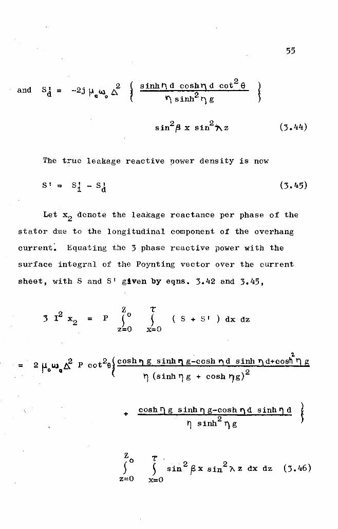
and S 1 ;::d 2 " 2
-JuU3Arel 0
2~ sinht"\dcosh'1dcot et Yj sinh2 t') g l
55
The true leakage reactive power density is now
8 1 ;:: S 1 - 8 11 d
Let x 2 denote the leakage reactance per phase of the
stator due to the longitudinal component of the overhang
current~ Equating the 3 phase reactive power with the
surface integral of the Poynting vector over the current
sheet, with 8 and SI given by eqns. 3.42 and 3.45,
=z
P ~ 0
z=o
T
~x=o( 8 + S r ) dx dz
;::
2cot2e~ cosh I) g sinh l) g-cosh !) d sinh!) d+cosh 'J g
~ y) (sinh '1 g + cosh ry g) 2
+ cosh l) g sinh!) g-cosh !) d sinh f) d ~I 2 ~
~ sinh Y). g
7:'.
~ -sin2 ~ x sin2
"l\ z dx dz (3.46)x=o
56
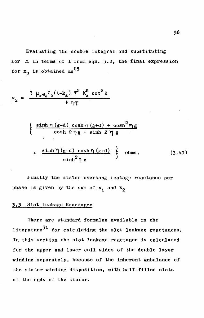
Evaluating the double integral and substituting
for ~ in terms of I from eqn. 3.2, the final expression
for x2 is obtained as25
3 ~o~oZo(1-kz) T2 ~ cot
2 eP'lT
~ sinh!) (g-d) cosht) (g+d) + COSh2ng( cosh 2 t')g + sinh 2 " g
+ sinh" (g-d) cosh'l (g+d)
sinh2 '1 gohms.
Finally the stator overhang leakage reactance per
phase is given by the sum of xi and x2
3.3 Slot Leakage Reactance
There are standard formulae available in the
literature3i for calculating the slot leakage reactances.
In this section the slot leakage reactance is calculated
for the upper and lower coil sides of the double layer
winding separately, because of the inherent wnbalance of
the stator winding disposition, with half-filled slots
at the ends of the stator.
57
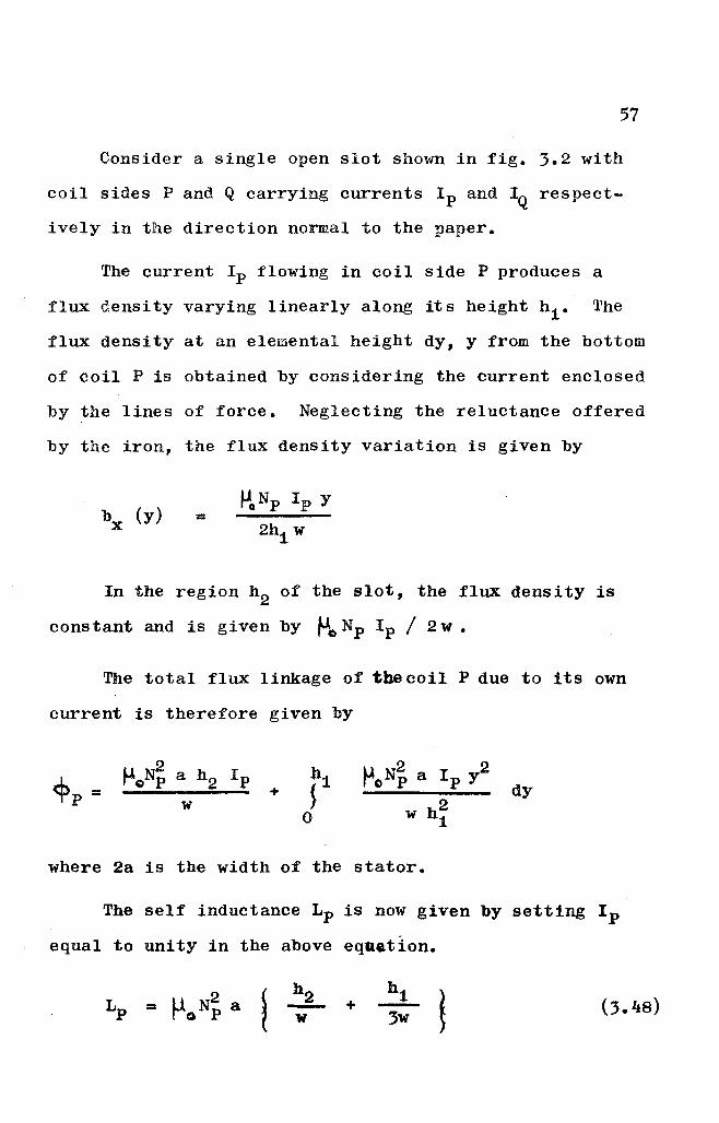
Consider a single open slot shown in fig. 3.2 with
coil sides P and Q carrying currents I p and IQ respect
ively in the direction normal to the paper.
The current Ip flowing in coil side P produces a
flux density varying linearly along its height hi. The
flux density at an elemental height dy, y from the bottom
of coil P is obtained by considering the current enclosed
by the lines of force. Neglecting the reluctance offered
by the iron, the flux density variation is given by
b (y)tJoNp I p Y
=x 2hi w
In the region h2 of the slot, the flux density is
constant and is given by fJC)N p I p / 2w.
The total flux linkage of the coil P due to its own
current is therefore given by
+ dy
where 2a is the width of the stator.
The self inductance Lp is now given by setting I p
equal to unity in the above equation.
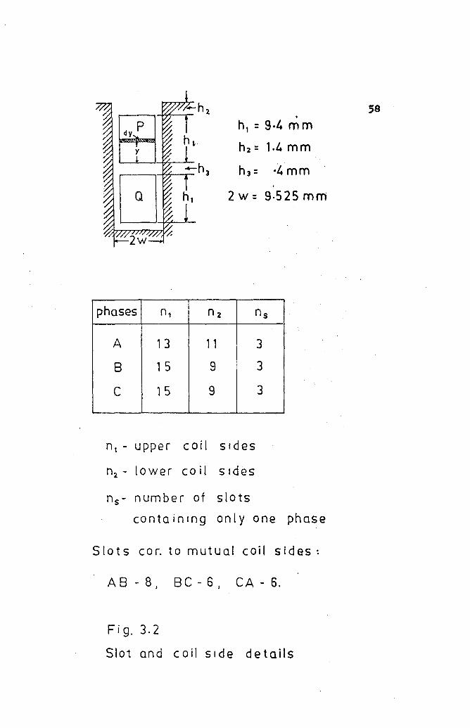
•h, : 9·4 m m
hz =1.4mm
h J = ·4 mm
2 w = 9·525 mm
59
phases n1 n2 ns
A 13 11 3
8 15 9 3
C 15 9 3
n, - upper coil sIdes
n2 - lower co il sIdes
ns - numbe r of slots
containing only one phase
Slots cor. tom ut u a I c 0 i I sides ~
A 8 - 8 I B C - 6 I CA - 6.
Fi g. 3.2
Slot and coil side details
59
The current I Q flowing in coil side Q sets up flux
density varying linearly along its height, while in the
slot region above Q, the flux density is constant, being
given by ~oNQ I Q / 2w.
Hence the total flux linkage of the coil Q due to
I Q is given by
dy
The self-inductance LQ is now given by putting
I Q = 1 so that
l!.N~ a ~"N: a hiLQ = ( hi +h2+h:; ) + (:;.49)w :;w
To obtain the mutual inductance MPQ' let Q carry a
current IQ• The field due to IQ is uniform in the region
h1 and h 2 and is given by
While the entire flux in region h2 links the coil P9
in fUll, the linkage in hi is linear in y. Hence the
mutual inductance MPQ' given by the flux linkage of P
due to unity current in Q is equal to
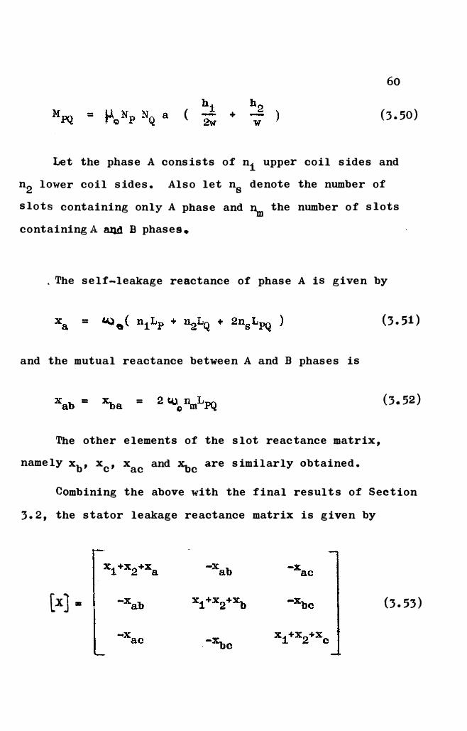
60
( + (3.50)
Let the phase A consists of n1 upper coil sides and
n2 lower coil sides. Also let n8 denote the number of
slots containing only A phase and� the number of slots
containing A aJld B phases •
. The self-leakage reactance of phase A is given by
=
and the mutual reactance between A and B phases is
=
The other elements of the slot reactance matrix,
namely xb, xc, xac and �care similarly obtained.
(3.51)
(3.52)
Combining the above with the final results of Section
3.2, the stator leakage reactance matrix is given by
[x) • (3.53)
61
3.4 Summary
The problem of calculating the leakage reactances
in a double-sided, sheet secondary type Linear Induction
Motor is considered in this chapter. The leakage fields
assume importance when the complete terminal characteri-
sation of the machine is desired, as discussed in the
subsequent chapters. In this sense, the results here
complement those of Chapter 2. The three-dimensional
field model enables computation of the 3 phase reactive
power flow in the coil end winding region and facili-
tates calculation of the 3 x 3 leakage reactance matrix.
It may be noted that the derivation does not employ any
empirical formula or factor and the final expressions
for the stator overhang and slot leakage reactances can
be evaluated using normal design data.