Embed Size (px)
Citation preview
Chapter 3 Chapter 3 Digital Communication 1
- 1 -
KyungHeeUniversity
Chapter 3: Baseband
Demodulation/Detection

Chapter 3 Chapter 3 Digital Communication 1
- 2 -
KyungHeeUniversity
풍선효과풍선효과
Idiots, it’s trade-off!!
Bit error Bit error PPBB
PowerEb/No
Bandwidth
W
Bitrate R

Chapter 3 Chapter 3 Digital Communication 1
- 3 -
KyungHeeUniversity
White NoiseWhite Noise
ACS PSD
( Ex ) Thermal noise : 0 ~ 1012 Hz
AWGN ( Additive White Gaussian Noise ) Channel
- Infinite Bandwidth :
- Pass through a specific channel
- If AWGN is correlated with one of a set of orthonormal functions
Bandlimited AWGN channel
0( )2n
NG f 0( ) ( )
2 n
NR
2 0var[ ( ) ] ( )2
Nn t df
( ) , j t
2 2 0
0var( ) [ ( ) ( ) ]
2
T
j j
Nn E n t t
the variance of the correlator output is given by
( Why ? Appendix C )

Chapter 3 Chapter 3 Digital Communication 1
- 4 -
KyungHeeUniversity
Three Major Functions of Digital ReceiverThree Major Functions of Digital Receiver
Filtering : - Reduce unwanted noise and interference
- Recover a baseband pulse with the best possible
SNR, free of any ISI (Inter-Symbol Interference
- Matched filter or Correlator
- Equalizing filter for channel – induced ISI
Sampling : Get the best signal components
Decision : Reduce the probability of error
( Note ) Detection : Decision – making process

Chapter 3 Chapter 3 Digital Communication 1
- 5 -
KyungHeeUniversity
Functional Block for DigitalFunctional Block for Digital Demodulation / Detection Procedure Demodulation / Detection Procedure
Frequencydown-
conversion
Receivingfilter
Equalizingfilter( )is t
AWGN
( )r t
Transmittedwaveform
Receivedwaveform
( ) ( ) ( ) ( )i cr t s t h t n t
Thresholdcomparison
H1
H2
Sampleat t = T
Demodulate & sample
For bandpasssignal
Compensation forchannel induced
ISI
Baseband pulse( possibly distorted )
( )z t
Baseband pulse
0( ) ( ) ( )iz t a t n t
( )z T
Sample ( teststatistic )
0( ) ( ) ( )iz T a T n T
Predetectionpoint
Detect
orim
iu
Message symbolor
channel symbol iu
im
Step 1waveform - to - sample transformation
Step 2decision making
( )z T
Optional
Essential

Chapter 3 Chapter 3 Digital Communication 1
- 6 -
KyungHeeUniversity
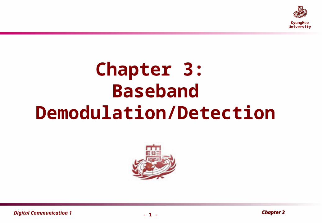
Vectorial Representation of Signal Waveforms (1)Vectorial Representation of Signal Waveforms (1)
N-dimensional orthogonal space
Orthogonal and orthonormal functions
–
, Kronecker delta function
Dfn : A space characterized by a set of N linearly independent functions , called basis function.
{ ( )}j t
1( )
0
for j kj k
otherwise
–
– If , then are called orthonormal functions. 1jK { ( )}j t
NkjforkjKdttt j
T
kj ,,2,1,][)()(0
NkjforkjdtT
kt
T
jt
T
T,,2,1,][
2cos
2cos
20
Cf)

Chapter 3 Chapter 3 Digital Communication 1
- 7 -
KyungHeeUniversity
Vectorial Representation of Signal Waveforms (2)Vectorial Representation of Signal Waveforms (2)
Any arbitrary function in the space can be expressed as a linear combination of N orthogonal waveforms, such that
– Compact form
1
( ) ( ) , 1, , ,N
i ij jj
S t a t i M N M
0
1( ) ( ) , 1, , , 0
T
ij i jj
a S t t dt i M t TK
– Coefficient form
– 1 11 1 12 2 1N N
2 21 1 22 2 2N N
M M1 1 M 2 2 MN N
( ) ( ) ( ) ( )
( ) ( ) ( ) ( )
( ) ( ) ( ) ( )
S t a t a t a t
S t a t a t a t
S t a t a t a t
1, ,j N
M symbols

Chapter 3 Chapter 3 Digital Communication 1
- 8 -
KyungHeeUniversity
Vectorial Representation of Signal Waveforms (3)Vectorial Representation of Signal Waveforms (3)
Observation :
– The set of signal waveforms , can be viewed as a set of vectors
3 31 1 32 2 33 3 3 31 32 33( ) ( ) ( ) ( ) ( , , )S t a t a t a t a a a S
{ ( )}iS t
(Ex.)
The task of the receiver is to decide whether has a close “resemblance”
to the prototype .
r
jS
The analysis of all demodulation of detection schemes involves this concept of distance
between a received waveform and a set of possible transmitted waveforms.
Refer to Fig. 3.4
},,,{)}({ 11 iNiii aaats
Chapter 3 Chapter 3 Digital Communication 1
- 9 -
KyungHeeUniversity
Example of Vector Representation
)(1 t
)(2 t
E
E
E
)2
cos(2
)( 0 M
it
T
EtSi
)(tSi
M
i2

Chapter 3 Chapter 3 Digital Communication 1
- 10 -
KyungHeeUniversity
Waveform EnergyWaveform Energy
Energy of the waveform over a symbol duration( )jS t
If , then
Average symbol energy :
sT
22
0 0
0
0
( ) ( ) ( )
( ) ( )
( ) ( )
T T
i i ij i
T
ij i ik kj k
T
ij ik i kj k
j k
E S t dt a t dt
a t a t dt
a a t t dt
Eq. (3.13) ~ Eq.(3.17)
1jK 2
1
N
i ijj
E a
1
1 M
s ii
E EM
Average bit energy : / ( / )b sE E k k bits symbol
][ kjKaa jikij

Chapter 3 Chapter 3 Digital Communication 1
- 11 -
KyungHeeUniversity
Variance of White Noise
▷ white Gaussian noise process, n(t), with zero mean and two-sided power spectral density,
▷ Noise variance is infinite, filtered AWGN is finite
▷ The output of each correlator, , t=T
▷ mean of
jn
jn

Chapter 3 Chapter 3 Digital Communication 1
- 12 -
KyungHeeUniversity
▷ variance of
▷ n(t) is zero-mean process
▷ The autocorrelation function
▷ If n(t) is assumed stationary, then Rn(t,s) is only a function of the time difference,
jn
)}()({),( sntnEstRn
st

Chapter 3 Chapter 3 Digital Communication 1
- 13 -
KyungHeeUniversity
▷ For a stationary random process, the power spectral density, Gn(f), and the autocorrelation function,Rn( ), form a Fourier transform pair.
▷ Since n(t) is white noise,
So,
2/)( 0NfGn
Inverse FT
1)() cf)(
22)( 020 N
dfeN
R fjn
1
2 0
2
N

Chapter 3 Chapter 3 Digital Communication 1
- 14 -
KyungHeeUniversity
Signal RepresentationSignal Representation
Transmitted signal : 1
2
( ) , 0 1( )
( ) , 0 0i
s t t T fors t
s t t T for
Received signal : ( ) ( ) ( ) ( ) 1, 2, ,i cr t s t h t n t i M
Output of receiving filter : ( ) ( ) ( )iz t a t n t
( )
( )
n T
z T
Output of sampler at t = T : ( ) ( ) ( )iz T a T n T
: Gaussian random variable ( n0 = n(T) )
: Gaussian random variable ( a1 = a1(T) , a2 = a2(T) )
convolution

Chapter 3 Chapter 3 Digital Communication 1
- 15 -
KyungHeeUniversity
Conditional pdf : -2
200 0
00
1 1( ) exp[ ] : 0 , var
22
np n mean iance
- : Likelihood function of s11
2
1
00
1 1( ) exp[ ]
22
zs
z ap
-2
2
2
00
1 1( ) exp[ ]
22
zs
z ap
Conditional pdf p ( z/s )Conditional pdf p ( z/s )
- If s1(t) is transmitted , then 1 0 z a n
- If s2(t) is transmitted , then 2 0 z a n
Fig. 3. 2.
: Likelihood function of s2
o no
σo
a1 a2

Chapter 3 Chapter 3 Digital Communication 1
- 16 -
KyungHeeUniversity
EEbb / N / N00
Analog communications : S/N ( or SNR ) figure of merit ( power signal )
0
sec
/ / sec
b bE S T S W Joule W
N N W N R W Hz W
Digital communications : Eb/N0 figure of merit
- Eb : bit energy , - N0 : one – sided PSD - S : signal power
Why Eb/N0 is a natural figure of merit ?
- Focusing on one symbol , the power ( averaged over all time ) goes to zero .
- Hence , power is not a useful way to characterize a digital waveform .- The symbol energy ( power integrated over Ts ) is a more useful parameter
for characterizing digital waveforms .
- Tb : bit duration[sec] - S : signal power[Watt] - N : noise power[Watt]

Chapter 3 Chapter 3 Digital Communication 1
- 17 -
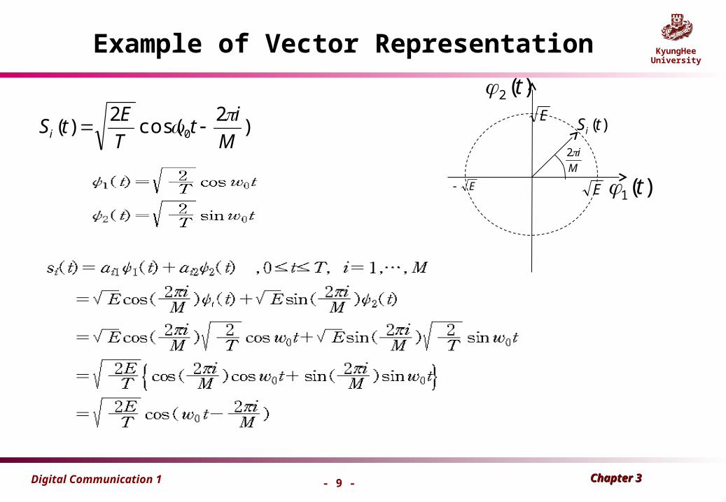
KyungHeeUniversity3.2 Detection of Binary Signal in Gaussian noise
Demodulation and Detection
• The received signal over Gaussian channel
Chapter 3 Chapter 3 Digital Communication 1
- 18 -
KyungHeeUniversity

Chapter 3 Chapter 3 Digital Communication 1
- 19 -
KyungHeeUniversity
is equal
a1 a2
H1
H2
Decision-making criterion

Chapter 3 Chapter 3 Digital Communication 1
- 20 -
KyungHeeUniversity
Minimum error criterion
ln 1 = 0

Chapter 3 Chapter 3 Digital Communication 1
- 21 -
KyungHeeUniversity
▷ Error Probability
and because of the symmetry of the probability density function
a1 a2
BER

Chapter 3 Chapter 3 Digital Communication 1
- 22 -
KyungHeeUniversity
Complementary error functionComplementary error function
212
( ) exp( )2x
uQ x du
212
( ) exp( ) 32x
xQ x for x
12(0)Q
(1) 0.1587Q
(2) 0.0228Q
( ) 0Q
x
Right half of N(0,1)

Chapter 3 Chapter 3 Digital Communication 1
- 23 -
KyungHeeUniversity
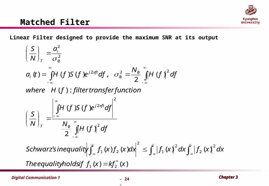
Matched Filter ( MF ) ( 1 )Matched Filter ( MF ) ( 1 )
A linear filter designated to provide the maximum SNR at its output for a given transmitted symbol waveform .
AWGN Channel , transmitted signal ( ) , 0s t t T
Matched Filter
h(t) , H(f)
Detector z(T)
1 or 0
threshold
sampleat t = T
PCM wavess(t)
WGN n(t)
Chapter 3 Chapter 3 Digital Communication 1
- 24 -
KyungHeeUniversityMatched Filter
)()(
)()()()('
)(2
)()(
:)(
)(2
,)()()(
*21
2
2
2
1
2
21
20
2
2
2020
2
20
2
xkfxfifholdsequalityThe
dxxfdxxfdxxfxfinequalitysSchwarz
dffHN
dfefSfH
N
S
functiontransferfilterfHwhere
dffHN
dfefSfHta
a
N
S
ftj
T
ftji
i
T
Linear Filter designed to provide the maximum SNR at its output

Chapter 3 Chapter 3 Digital Communication 1
- 25 -
KyungHeeUniversity
elsewhere
TttTksth
efkSfH
FilterMatchedFunctionTransferOptimal
N
EdffS
NN
S
dffSdffHdfefSfH
fTj
T
ftj
0
0)()(
)()(
)(
2)(
2
)()()()(
2*
0
2
0
22
2
2
0 T
0 T
s(t)
h(t)
Matched filter 일 때 , S/N 이 최대값이 됨을 증명했다 .

Chapter 3 Chapter 3 Digital Communication 1
- 26 -
KyungHeeUniversity
Correlator Realization of the MFCorrelator Realization of the MF
0
( ) ( ) ( ) ( ) ( ) ( ( ) ( ) ) t
z t r t h t r h t d h t s T t
0 0( ) [ ( ) ] ( ) ( )
t tr s T t d r s T t d
At t = T , : Cross – correlation of with0
( ) ( ) ( )T
z T r s d ( )r t ( )s t
( Observation ) Integration – and – Dump Filter
For NRZ Waveform , ( ) 1 0s t for t T
0( ) ( )
Tz T r d
( Note ) The correlator output and the matched filter output are the same only at time t = T . ( Refer to Fig. 3.7 )

Chapter 3 Chapter 3 Digital Communication 1
- 27 -
KyungHeeUniversity
▷ Correlation Realization of the Matched Filter
MF output
Matched Filter
When t=T
0( ) ( )* ( ) ( ) ( )
tz t r t h t r h t d
0( ) ( ) [ ]
Tz T r S d
0( ) [ ( )]
tr S T t d

Chapter 3 Chapter 3 Digital Communication 1
- 28 -
KyungHeeUniversity
Equivalence of Matched Filter and CorrelatorEquivalence of Matched Filter and Correlator
h( T - t )r(t) = si (t) + n(t) z (T)
Matched tos1(t) - s2(t)
0T
r(t) = si (t) + n(t) z (T)
s1(t) - s2(t)
Matched Filter
Correlator

Chapter 3 Chapter 3 Digital Communication 1
- 29 -
KyungHeeUniversity
Probability of Bit Error ( PProbability of Bit Error ( PB B ))
for Binary Signaling (1)for Binary Signaling (1)
1 2
0 0 0
(1 )
2 2d b
B
E Ea aP Q Q Q
N N
( ) Output SNR at time t = T :
21 2 1 2
20 0
( )
/ 2 2 2d d
T o
E Ea a a aS
N N N
22 2
1 2 1 2 1 20 0 0 0
1 20
( ) ( ) ( ) ( ) ( ) ( )
12 ( ) ( ) cos
2 1
T T T T
d
T
b b bb
b
E s t s t dt s t dt s t dt s t s t dt
E E E s t s t dtE
E
Cross-correlation coefficient -
1<ρ<1 ρ =0 if uncorrelated
a1 a2

Chapter 3 Chapter 3 Digital Communication 1
- 30 -
KyungHeeUniversity
Probability of Bit Error ( PProbability of Bit Error ( PB B ))
for Binary Signaling (2)for Binary Signaling (2)
0
(1 )bB
EP Q
N
for antipodal signaling 0
2 bB
EP Q
N
( 1 )
for orthogonal signaling 0
bB
EP Q
N
( 0)
1 1 2 1
01 2 0
( ) ( ) , ( ) ( )
2 ,2
b b
b b b
s t E t s t E t
Na a E E E
s1s2
s1
s2
bE bE
bE
bE
2
1
bd EE 4
2)2( bd EE
)2
(0N
EQP d
B

Chapter 3 Chapter 3 Digital Communication 1
- 31 -
KyungHeeUniversity
Comparison of Binary SignalingComparison of Binary Signaling
At the same bit energy Eb and noise condition No,
)2
(0N
EQP d
B
Compare
21 20
( ( ) ( ) )T
dwhere E s t s t dt

Chapter 3 Chapter 3 Digital Communication 1
- 32 -
KyungHeeUniversity
Unipolar Signaling (1)Unipolar Signaling (1)
1( ) , 0 for binary 1 ( 0)s t A t T A
Signal
–
0 ( ) 0 , 0 for binary 0s t t T –

Chapter 3 Chapter 3 Digital Communication 1
- 33 -
KyungHeeUniversity
Unipolar Signaling (1)Unipolar Signaling (1)
Detection Process
)()()( 1 tntstr
TAAdttnAEtsTzETaT 2
011 }))(({)}(|)({)(
Atsts )]()([ 21
0})({)}(|)({)(022 T
AdttnEtsTzETa
22
221
0
TAaa
)()2
()2
(00
2
0 N
EQ
N
TAQ
N
EQP bd
B
2
2TAEb
Chapter 3 Chapter 3 Digital Communication 1
- 34 -
KyungHeeUniversity
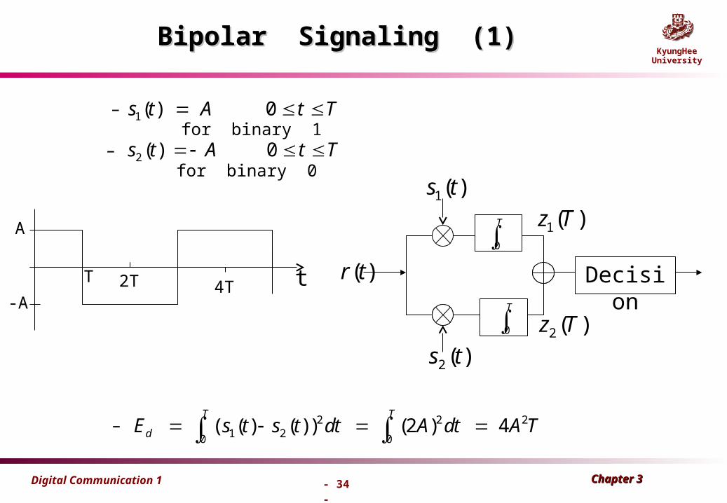
Bipolar Signaling (1)Bipolar Signaling (1)
– for binary 1
– for binary 0
1( ) 0s t A t T
2 ( ) 0s t A t T
– 2 2 21 20 0
( ( ) ( ) ) (2 ) 4T T
dE s t s t dt A dt A T
A
-A
T 2T 4T t Decision
T
0
T
0
)(1 ts
)(2 ts
)(2 Tz
)(1 Tz
)(tr

Chapter 3 Chapter 3 Digital Communication 1
- 35 -
KyungHeeUniversity
0 0 0
4 2
2 2d b b
B
E E EP Q Q Q
N N N
Refer to Fig. 3.14
Average bit energy :2 2
2
2 4d
b
EA T A TE A T
Bipolar Signaling (2)Bipolar Signaling (2)
)(0N
EQP b
B
)2
(0N
EQP b
B
3dB
10-2
10-4
)(0
dBN
Eb14-1
Chapter 3 Chapter 3 Digital Communication 1
- 36 -
KyungHeeUniversity
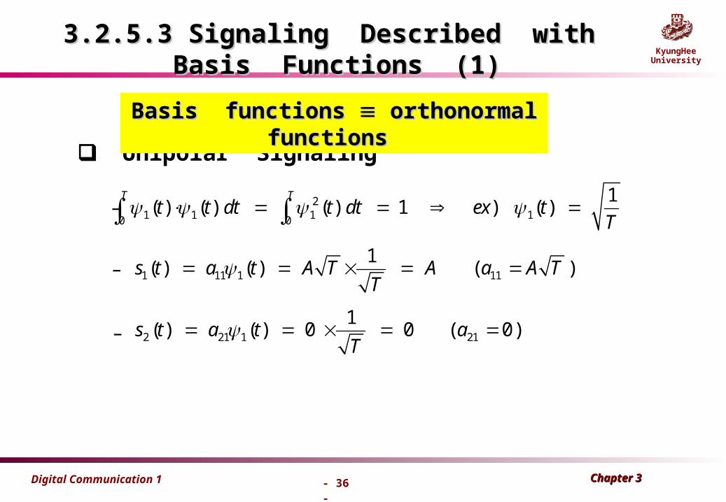
3.2.5.3 Signaling Described with Basis Functions (1)3.2.5.3 Signaling Described with Basis Functions (1)
Unipolar Signaling
–
1 11 1 11
1( ) ( ) ( )s t a t A T A a A T
T
21 1 1 10 0
1( ) ( ) ( ) 1 ) ( )
T Tt t dt t dt ex t
T
2 21 1 21
1( ) ( ) 0 0 ( 0)s t a t a
T
–
–
Basis functions Basis functions orthonormal functions orthonormal functions

Chapter 3 Chapter 3 Digital Communication 1
- 37 -
KyungHeeUniversity
Detection process
1 1 11 1 1 110 0( ) ( ) ( ) ( ) ( ) ( ) 2
T T
ba T E r t t dt E a t n t t dt a E
2 1 21 1 1 210 0( ) ( ) ( ) ( ) ( ) ( ) 0
T Ta T E r t t dt E a t n t t dt a
2 20
2 2b
A T A TE
2 bA T E
1( )t
21
0
a 11
2 bE
a
3.2.5.3 Signaling Described with Basis Functions (2)3.2.5.3 Signaling Described with Basis Functions (2)
Chapter 3 Chapter 3 Digital Communication 1
- 38 -
KyungHeeUniversity
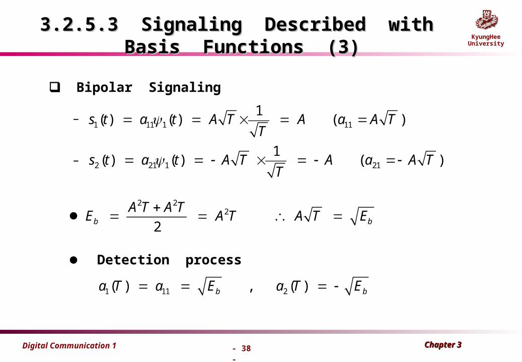
Bipolar Signaling
–1 11 1 11
1( ) ( ) ( )s t a t A T A a A T
T
2 21 1 21
1( ) ( ) ( )s t a t A T A a A T
T
2 22
2b b
A T A TE A T A T E
Detection process
1 11 2( ) , ( )b ba T a E a T E
3.2.5.3 Signaling Described with Basis Functions (3)3.2.5.3 Signaling Described with Basis Functions (3)
–

Chapter 3 Chapter 3 Digital Communication 1
- 39 -
KyungHeeUniversity
Observations on Binary SignalingObservations on Binary Signaling
We can see that a 3-dB error performance improvement for bipolar
signaling compared with unipolar signaling .
Bandpass antipodal signaling ( e.g. , BPSK ) has the same PB
performance as baseband antipodal signaling ( e.g. , bipolar pulses )
with MF detection .
Bandpass orthogonal signaling ( e.g. , orthogonal FSK ) has the same
PB performance as baseband orthogonal signaling ( e.g. , unipolar pulses )
s1s2
bE bE
bd EE 4
s1
s2
bE
bE
2
1
2)2( bd EE

Chapter 3 Chapter 3 Digital Communication 1
- 40 -
KyungHeeUniversity
Bandlimited ChannelBandlimited Channel
So far , digital communication over on AWGN channel
– No bandwidth requirement and/or channel distortion
Now , digital communication over a bandlimited baseband channel
– Bandwidth constraint and/or channel distortion
– Modeled as a linear filter channel with a limited bandwidth
– Telephone channels , microwave , satellite etc.

Chapter 3 Chapter 3 Digital Communication 1
- 41 -
KyungHeeUniversity
Linear Filter ChannelLinear Filter Channel
More stringent requirements on the design of modulation signals
Preclude the use of rectangular pulses at the modulator output
Distort the transmitted signal
Cause the intersymbol interference ( ISI ) at the demodulator
Frequency responses of channel are distorted , thus non-flat or frequency selective channels .
Increase PB
Requires channel equalizers to compensate for the distortion caused by the transmitter and the channel .

Chapter 3 Chapter 3 Digital Communication 1
- 42 -
KyungHeeUniversity
FT
FT
Inter-symbol interference
Infinite bandwidth
Our dilemma!!
양쪽에서 조금씩 타협
Infinite duration and non-causal
t
tf
f

Chapter 3 Chapter 3 Digital Communication 1
- 43 -
KyungHeeUniversity
Typical Baseband Digital System
System Transfer function :( ) ( ) ( ) ( )t c rH f H f H f H f
(a)
H ( f )h ( t )
Detector
T T
k{ x }
1x 2x
3xt = kT
k{ x }
(b)
Noise
Pulse 1 Pulse 2
Trasmittingfilter
ChannelReceiving
filterDetector
T T
k{ x }
1x 2x
3x
Noise
t = kT
k{ x }
Transmit Channel Receiving
Equivalent model with two pulses

Chapter 3 Chapter 3 Digital Communication 1
- 44 -
KyungHeeUniversity
3.3 Inter-symbol Interference ( ISI )
ISI : Due to the effects of system filtering , the
received pulses can overlap one another.
The tail of a pulse can smear into adjacent symbol
Interfere with the detection process
Degrade the error performance
Even in the absence of noise, the effects of filtering
and channel-induced distortion lead to ISI.
( ) ( )t cH f H f

Chapter 3 Chapter 3 Digital Communication 1
- 45 -
KyungHeeUniversity
Ideal Nyquist Filter for Zero ISI (1)
Theoretical Minimum Nyquist BW =
Ideal Nyquist pulse :
infinite tail find practical one
sR
s
1R / 2
2T
: Symbol rate [ symbols / sec ]
h(t) sin c( t / T )
f
(a)
H(f)
T
t
h(t)
01
2
T
1
2T
1
0
-T T(b)
h(t - T)
–

Chapter 3 Chapter 3 Digital Communication 1
- 46 -
KyungHeeUniversity
Ideal Nyquist Filter ( apulse ) for Zero ISI (2)
Nyquist filters are not realizable
since they have the infinite filter length.
Observation : (i) Even though has long tails, a tail pass through zero amplitude at t = T when is to be sampled. (ii) If the sample timing is perfect, thee will be no ISI degradation introduced.
Among the class of Nyquist filters, the most popular ones are the raised cosine and the square root-raised cosine filters.
h( t - T ) h(t)
Chapter 3 Chapter 3 Digital Communication 1
- 47 -
KyungHeeUniversity
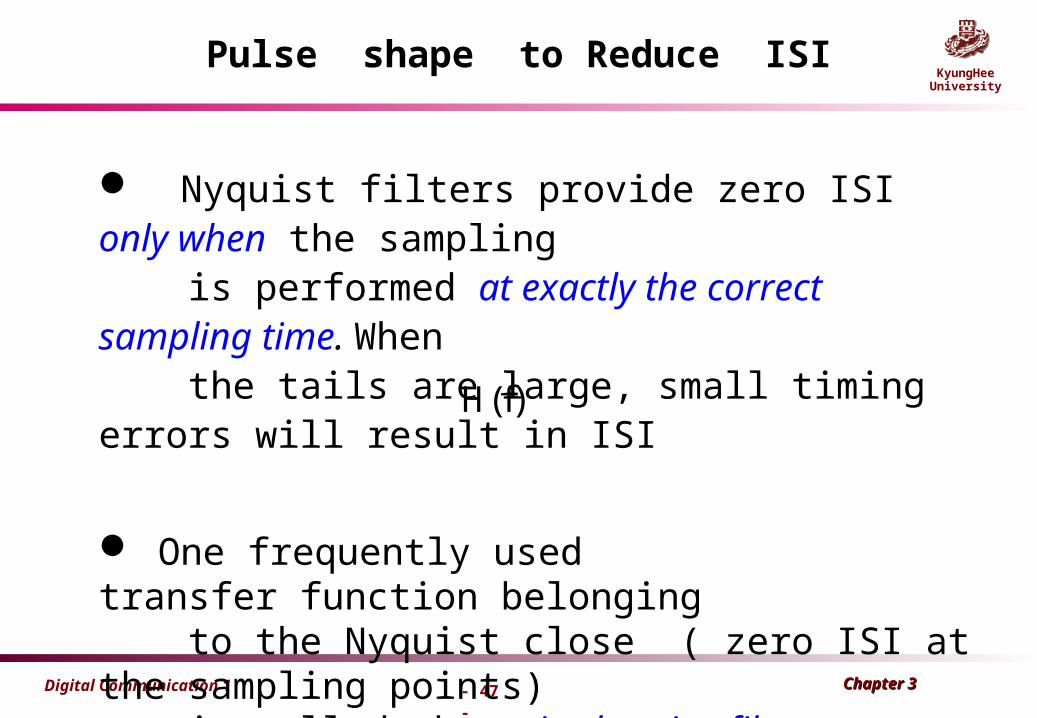
Pulse shape to Reduce ISI
Nyquist filters provide zero ISI only when the sampling is performed at exactly the correct sampling time. When the tails are large, small timing errors will result in ISI
One frequently used transfer function belonging to the Nyquist close ( zero ISI at the sampling points) is called the raised-cosine filter.
H(f)

Chapter 3 Chapter 3 Digital Communication 1
- 48 -
KyungHeeUniversity
Raised – Cosine Filter ( R-C Filter )
Wffor
WfWWforWW
WWf
WWffor
fH
||0
||22||
4cos
2||1
)( 00
02
0
00 /)( WWWr
)( 0WWbandwidthexcess T
WbandwidthNyquist2
1min 0
2cos~0cos
2
)~0cos(1
0W0W W
r =1
r =0.5
r =0
fTRrateSymbol /1

Chapter 3 Chapter 3 Digital Communication 1
- 49 -
KyungHeeUniversity
Raised – Cosine Filter ( R-C Filter ) (2)
Impulse Response :
: Minimum Nyquist Filter0
1w
2T
0
0
w wr
w
: roll-off factor ( 0 r 1 )
s
1R [Hz]
T : symbol rate
s
1w (1 r )R
2 DSB sw (1 r )R
20
000
)(41
)(2cos)2(2)(
tWW
tWWtWncsiWth
Baseband bandwidth
Double-sided bandwidth

Chapter 3 Chapter 3 Digital Communication 1
- 50 -
KyungHeeUniversity
Baseband and double-sideband bandwidth
Baseband bandwidth
)(tx tftxtx cc 2cos)()(
tfc2cos Local oscillator
|)(| fX
mfmf f
|)(| fX c
mc ff mc ff fmc ff
double-sideband bandwidth
mc ff

Chapter 3 Chapter 3 Digital Communication 1
- 51 -
KyungHeeUniversity
Spectrum of Raised Cosine Pulse• r=0 corresponds to sinc(.) function
f (Hz)
1.0
0.5
(1 )Wo r Wo W
Wo r Wo r
sDSB RrW )1( T
Rs
1
|)(| fH
Chapter 3 Chapter 3 Digital Communication 1
- 52 -
KyungHeeUniversity
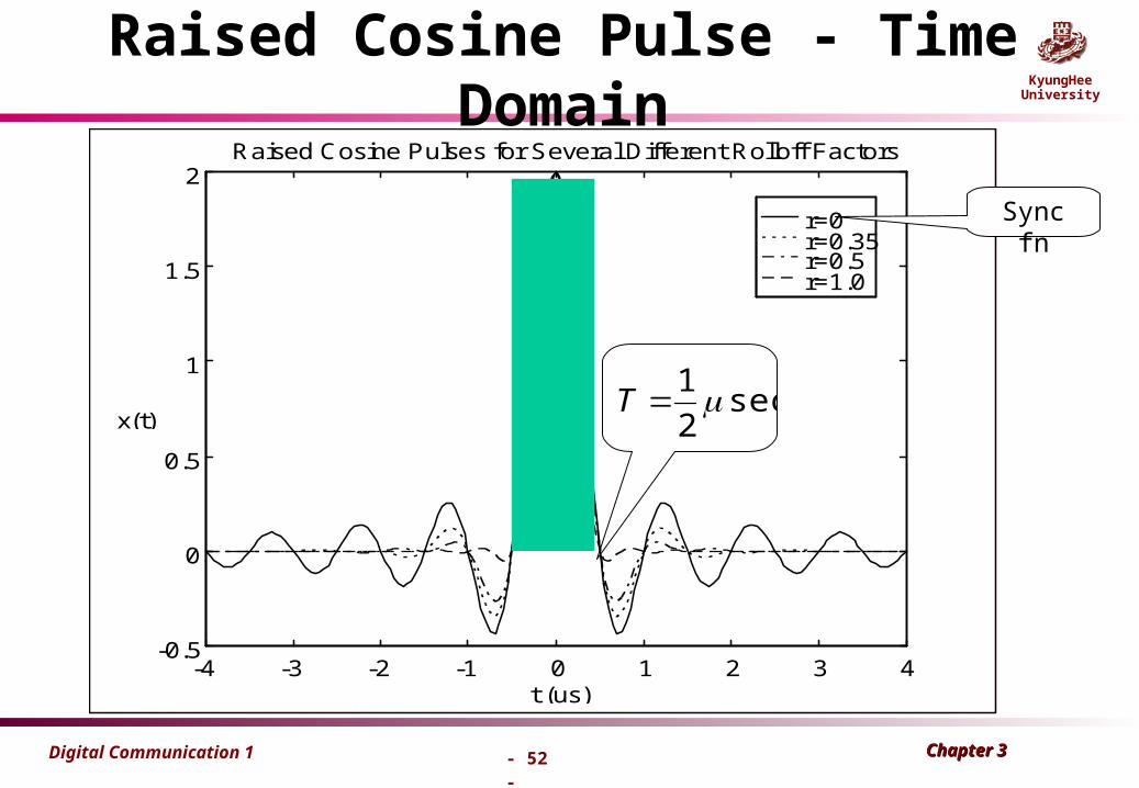
Raised Cosine Pulse - Time Domain
r=0r=0.35r=0.5r=1.0
-4 -3 -2 -1 0 1 2 3 4-0.5
0
0.5
1
1.5
2
t (us)
x(t)
Raised Cosine Pulses for Several Different Rolloff Factors
Sync fn
sec2
1 T

Chapter 3 Chapter 3 Digital Communication 1
- 53 -
KyungHeeUniversityRaised Cosine Pulse - Frequency Domain
r=0r=0.35r=0.5r=1.0
-5 0 5-120
-100
-80
-60
-40
-20
0
20
40
f (MHz)
|X(f)|^2 (dB)
Energy Spectrum of Raised Cosine Pulses
MHzW 10

Chapter 3 Chapter 3 Digital Communication 1
- 54 -
KyungHeeUniversity
Implementation of Raised Cosine Pulse
• Can be digitally implemented with an FIR filter
• Analog filters such as Butterworth filters may approximate the tight shape of this spectrum
• Practical pulses must be truncated in time– Truncation leads to sidelobes - even in RC pulses
• Sometimes a “square-root” raised cosine spectrum is used when identical filters are implemented at transmitter and receiver– We will discuss this more for “matched filtering.”

Chapter 3 Chapter 3 Digital Communication 1
- 55 -
KyungHeeUniversity
Bandwidth of Raised Cosine Pulses
• For PCM system: 2n=L (1 sample = n bits)
– is a parameter called “roll-off factor”
• Special cases:– r = 0 is just an Sa(.) function
– r = 1 is the largest possible value
– r = 0.35 is used in U.S. Digital Cellular (IS-54/136) standard
– r = 0.22 is used in WCDMA (3G) standard
0 1 r
1Hz
2SSB s
rBW f n
SSB s
1W (1 r )R
2 SSB
Sampling rate

Chapter 3 Chapter 3 Digital Communication 1
- 56 -
KyungHeeUniversity
(i) When r = 1, the required excess bandwidth is
100% and the tails are quite small. (ii) Bandpass - modulated signals ( chap. 4 ), such as
Amplitude-Shift Keying (ASK) and Phase-Shift
Keying (PSK), require twice the transmission
bandwidth of the equivalent baseband signals. WDSB
(iii) The larger the filter roll-off, the shorter will be
the pulse tails ( which implies smaller tail amplitudes ).
Raised – Cosine Filter ( R-C Filter ) (3)
SSB s
1W (1 r )R
2

Chapter 3 Chapter 3 Digital Communication 1
- 57 -
KyungHeeUniversity
(v) The smaller the filter roll-off is,
the smaller the excess BW will be.
Increase the signaling rate or the number of users
that can simultaneously use system.
The greater sensitivity to timing errors.
(iv) large r Small tail’s exhibit less sensitivity to timing error’s and thus make for small degradation due to ISI.
Raised – Cosine Filter ( R-C Filter ) (4)
SSB s
1W (1 r )R
2

Chapter 3 Chapter 3 Digital Communication 1
- 58 -
KyungHeeUniversity
FT
FT
Inter-symbol interference
Infinite bandwidth
Recall our dilemma!!
양쪽에서 조금씩 타협
Infinite duration and non-causal
t
tf
f
r=0
Chapter 3 Chapter 3 Digital Communication 1
- 59 -
KyungHeeUniversity
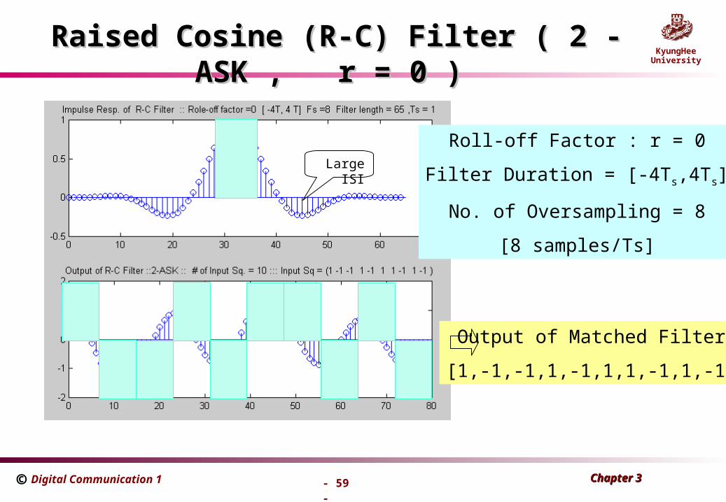
Raised Cosine (R-C) Filter ( 2 - ASK , r = 0 )Raised Cosine (R-C) Filter ( 2 - ASK , r = 0 )
©
Roll-off Factor : r = 0
Filter Duration = [-4Ts,4Ts]
No. of Oversampling = 8
[8 samples/Ts]
Output of Matched Filter
[1,-1,-1,1,-1,1,1,-1,1,-1]
Large ISI

Chapter 3 Chapter 3 Digital Communication 1
- 60 -
KyungHeeUniversity
Raised Cosine Filter ( 2 - ASK , r = 0.5 )Raised Cosine Filter ( 2 - ASK , r = 0.5 )
©
Roll-off Factor : r = 0.5
Filter Duration = [-4Ts,4Ts]
No. of Oversampling = 8
Output of Matched Filter
[1,-1,-1,1,-1,1,1,-1,1,-1]

Chapter 3 Chapter 3 Digital Communication 1
- 61 -
KyungHeeUniversity
Raised Cosine Filter ( 2 - ASK , r = 1 )Raised Cosine Filter ( 2 - ASK , r = 1 )
©
Roll-off Factor : r = 1.0
Filter Duration = [-4Ts,4Ts]
No. of Oversampling = 8
Small ISI

Chapter 3 Chapter 3 Digital Communication 1
- 62 -
KyungHeeUniversity
3.3.2 Two types of Error-performance Degradation
Without ISI
– theoretical
practical
0/ 10bE N dB
With ISI – More may not help the ISI problem.
0/bE N
– Equalization will help.
510BP
dBNEb 12/ 0
10 12
510BP
0/ NEb
10 12
510BP
0/ NEb
110BP
110BP
Chapter 3 Chapter 3 Digital Communication 1
- 63 -
KyungHeeUniversity
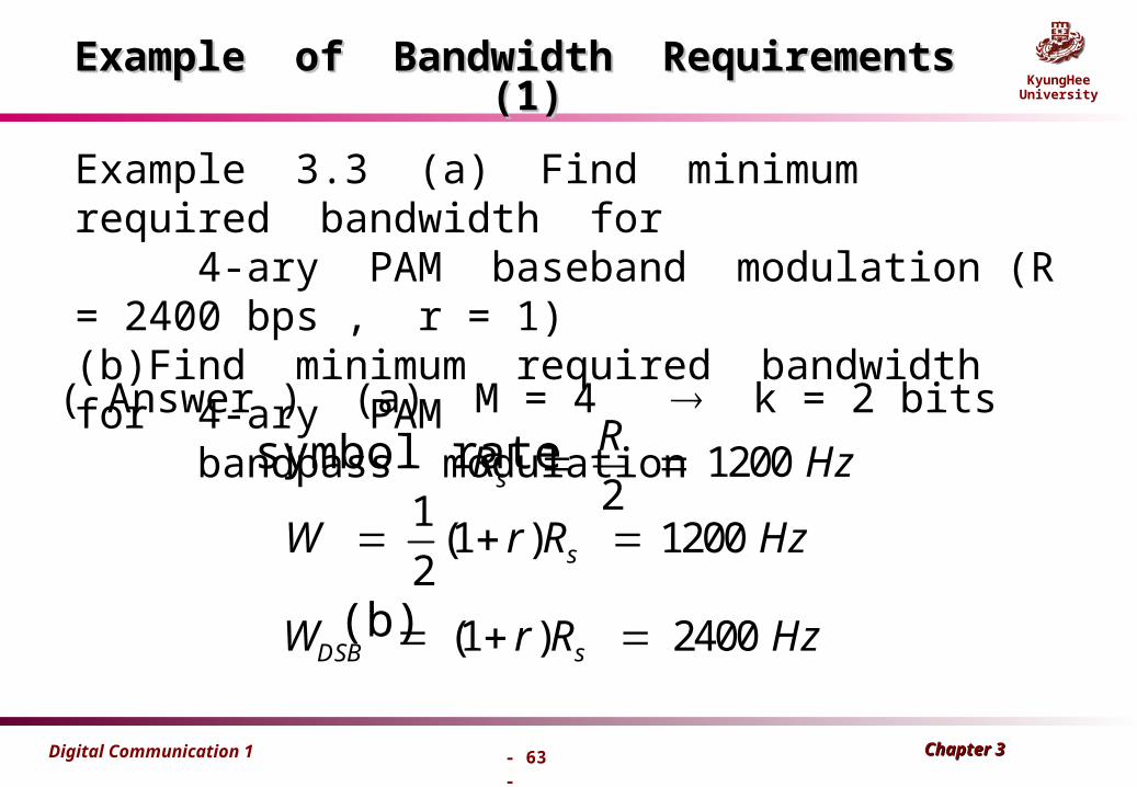
Example of Bandwidth Requirements (1)Example of Bandwidth Requirements (1)
Example 3.3 (a) Find minimum required bandwidth for 4-ary PAM baseband modulation (R = 2400 bps , r = 1) (b)Find minimum required bandwidth for 4-ary PAM bandpass modulation
( Answer ) (a) M = 4 k = 2 bits symbol rate
(b)
12002s
RR Hz
1(1 ) 1200
2 sW r R Hz
(1 ) 2400DSB sW r R Hz

Chapter 3 Chapter 3 Digital Communication 1
- 64 -
KyungHeeUniversity
Ex 3.4) Digital Telephone Circuits ( PCM Waveform )
– 3 kHz analog voice 8 bit ADC fs = 8kHz – Bit rate : R = 8000 8 bits = 64 kHz – For ideal Nyquist Filtering ,
Note) Binary signaling with a PCM waveform requires at least eight times the BW required for the analog channel . needs speech codec, 10kbps
(analog BW : guard-band + 3 kHz = 4 kHz )
132
2 2PCM
RW kHz
T
Example of Bandwidth Requirements (2)Example of Bandwidth Requirements (2)
Chapter 3 Chapter 3 Digital Communication 1
- 65 -
KyungHeeUniversity
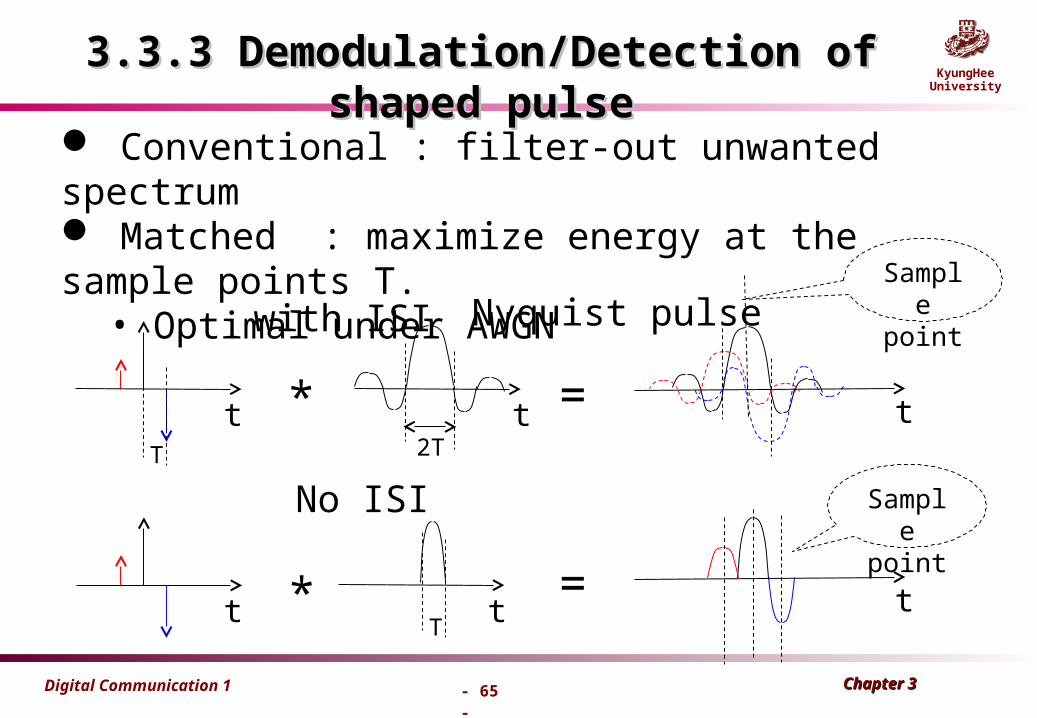
3.3.3 Demodulation/Detection of shaped pulse3.3.3 Demodulation/Detection of shaped pulse
Conventional : filter-out unwanted spectrum Matched : maximize energy at the sample points T.
• Optimal under AWGN
* =
* =
No ISI
with ISI Nyquist pulse
2TT
T
t
t t
t t
t
Sample point
Sample point

Chapter 3 Chapter 3 Digital Communication 1
- 66 -
KyungHeeUniversity
3.3.3 Demodulation/Detection of shaped pulse3.3.3 Demodulation/Detection of shaped pulse
Nyquist waveform observation (i) The square-root raised cosine filter non zero ISI (ii) transmitter output not exact original samples (iii) MF(matched filter) output zero ISI at the sample points.
[+1 +1 -1 +3 +1 +3] [+1 +1 -1 +3 +1 +3]
transmitter output Matched filter output Channel
correlator

Chapter 3 Chapter 3 Digital Communication 1
- 67 -
KyungHeeUniversity
Eye PatternEye Pattern
Oscilloscope display for the received signalon the vertical input with the horizontal sweep
rate 1/Ts
The optimum sampling time corresponds tothe maximum eye opening , yielding the greatest
protection against noise .
If there were no filtering in the system , thenthe system response would yield ideal rectangular
pulse shapes . ( no filtering BW corresponding to the transmission of the data pulse is infinite )
As the eye closes , ISI is increasing ; as the eyeopens , ISI is decreasing .
DA : Measure of distortion caused by ISI
JT : Measure of the timing jitter
MN : Measure of noise margin
ST : Sensitivity-to timing error

Chapter 3 Chapter 3 Digital Communication 1
- 68 -
KyungHeeUniversity
Practical Eye Pattern for ASK (or PAM)

Chapter 3 Chapter 3 Digital Communication 1
- 69 -
KyungHeeUniversity
Type of Eye Pattern

Chapter 3 Chapter 3 Digital Communication 1
- 70 -
KyungHeeUniversity
Eye Pattern ( 4 – ASK ) with Roll-off FactorEye Pattern ( 4 – ASK ) with Roll-off Factor
©
r = 0
r = 0.5
r = 0.25
r = 1.0