Embed Size (px)
Citation preview

52
CHAPTER 3
Design and Routing of Fault-tolerant Networks
In this chapter three newly designed fault-tolerant irregular Multistage
Interconnection Networks have been presented, namely, Irregular Augmented Shuffle
Exchange Network (IASEN), Improved Four Tree Network (IFTN) and Irregular
Augmented Baseline Network (IABN). Also, the network structure, routing capability,
fault-tolerance and cost of these MINs have been analyzed and explained in detail.
Besides, these parameters have been explained for existing MINs of Augmented Shuffle
Exchange Network (ASEN-2), Four Tree (FT) Network and Augmented Baseline
Network (ABN) for comparison and better understanding.
3.1 Introduction
Designing a MIN that is cost-effective, fault-tolerant and exhibits multi-path
routing capability has always been a challenging task for the network designers. With
this view, in this research three new irregular MINs have been designed and analyzed.
The focus of the designing has been irregular networks as
There has been a lesser emphasis on the irregular MINs in the existing
research literature. These possess an unequal and mostly lesser number of
switches and thereby provide cost advantage compared to their regular
counterparts.
These are inherently multi-path and provide good fault-tolerance in most of
the cases.

53
Before, explaining the design of these MINs it is important to understand the design
principles explained in the next section.
3.2 Basic Principles of Network Design
Design principles proposed by Bermond et al. (1989) are as under:
a) Small and fixed degree: The degree of a network topology can be defined as
the maximum number of connections to a component. A larger degree will
compromise the overall scalability of the system, it also means more wiring.
Thus a small or fixed maximum degree is desirable.
b) Small transmission delay: The diameter of a network topology can be defined
as the maximum distance between any two components. A small diameter is
desirable since it is proportional to sending a message from one component to
another.
c) Maximum fault tolerance: The network should function properly regardless of
an edge or vertex failure. The maximum connectivity is desirable because it is
the maximum fault tolerance of the network.
d) Easy routing algorithm: Routing is considered to be an important function in
communication networks. It is responsible for specifying a fixed route between
two components for communication.
e) Embeddability of other topologies: This is a crucial issue that deals with the
ability of architecture to take advantage of an algorithm developed for a
different type of architecture.
f) Large bisection width: The bisection width is defined as the minimum number
of edges, whose removal will result in two connected components of
54
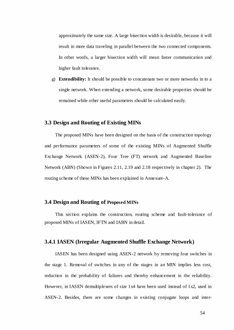
approximately the same size. A large bisection width is desirable, because it will
result in more data traveling in parallel between the two connected components.
In other words, a larger bisection width will mean faster communication and
higher fault tolerance.
g) Extendibility: It should be possible to concatenate two or more networks in to a
single network. When extending a network, some desirable properties should be
remained while other useful parameters should be calculated easily.
3.3 Design and Routing of Existing MINs
The proposed MINs have been designed on the basis of the construction topology
and performance parameters of some of the existing MINs of Augmented Shuffle
Exchange Network (ASEN-2), Four Tree (FT) network and Augmented Baseline
Network (ABN) (Shown in Figures 2.11, 2.19 and 2.18 respectively in chapter 2). The
routing scheme of these MINs has been explained in Annexure-A.
3.4 Design and Routing of Proposed MINs
This section explains the construction, routing scheme and fault-tolerance of
proposed MINs of IASEN, IFTN and IABN in detail.
3.4.1 IASEN (Irregular Augmented Shuffle Exchange Network)
IASEN has been designed using ASEN-2 network by removing four switches in
the stage 1. Removal of switches in any of the stages in an MIN implies less cost,
reduction in the probability of failures and thereby enhancement in the reliability.
However, in IASEN demultiplexers of size 1x4 have been used instead of 1x2, used in
ASEN-2. Besides, there are some changes in existing conjugate loops and inter-

55
connections amongst the switches in different stages. The IASEN of 16x16 has been
shown in Figure 3.1.
3.4.1.1 Construction of IASEN
An IASEN of size N x N (i.e. N sources and N destinations) has been designed
using two identical groups of G0 and G1, each having N/2 sources and an equal number
of destinations. This MIN has total n-1 stages (where n=log2N). All the stages except
the last stage, i.e., stages 0 to n-2 have 3x3 switches in them. Only the last stage consists
of 2x2 switches. A sub-network is formed via a group of size N/2 switches and their
associated multiplexers and demultiplexers. The IASEN of size 16x16 consists of two
identical sub-networks, G0 and G1.
Let any arbitrary source and destination be depicted by S and D respectively in the
binary form as under.
S=s0, s1,…,sn-2,sn-1 , where, s0 is MSB and sn-1 is LSB.
D=d0, d1,…,dn-2,dn-1 , where, d0 is MSB and dn-1 is LSB
A source is connected to switches of the stage 0 as follows:
(i) 1st request goes to primary switch.
(ii) 2nd request goes to s0, s1,…,s′n-2 ,sn-1
(iii) 3rd request goes to s0′, s1,…,sn-2 ,sn-1
(iv) 4th request goes to s0′, s1,…,(sn-2 = s0′), sn-1

56
Figure 3.1 : Irregular Augmented Shuffle Exchange network (IASEN) of 16x16
In order to understand all the paths and routing through the MIN, a redundancy
graph is convenient and important. They are also useful in determining properties of a
multi-path MIN, such as the number of faults tolerated and selecting the type of
rerouting possibilities (Kumar & Reddy, 1997). Besides, they are also useful in
determining all the available paths between a source and destination pair in a MIN.
Therefore, the redundancy graph of IASEN has been given below.
3.4.1.2 Redundancy Graph of IASEN
In Figure 3.1 the switches A and B in stage 0 of sub-network G0 are used as the
primary and the secondary switches, thus lead to primary and secondary path
respectively. Whereas switches E and F of sub-network G1 are used as alternate
G0
G1

57
primary# and the secondary# switch, allowing alternate primary and secondary paths
respectively. These paths have been shown through a redundancy graph in Figure 3.2.
Figure 3.2 : Redundancy Graph of IASEN
3.4.1.3 Routing Scheme for IASEN
In a multistage interconnection network a routing tag is used to describe the path
to be followed by a request to route itself from a given source to a known destination.
Let the selected source S and destination D be represented in binary codes as:
S=s0, s1… sn-2, sn-1
D=d0, d1… dn-2, dn-1
Following procedure is used to route a request from a given source say S to the desired
destination say D.
1) The source S selects one of the sub-networks G0 or G1 based on the most
significant bit of the destination D (i.e. d0). In one sub-network there exist
Primary
Secondary
Primary#
Secondary#

58
two types of paths viz. primary and secondary between any of the selected
source-destination pairs. Primary path is one, which is the shortest from a
given source to the desired destination. An alternate path (involving more
switches and stages) is known as secondary path. Each source attempts entry
into its primary sub-network via its primary path. If the primary path is not
available or faulty (i.e. either MUX or primary switch or both are faulty),
then the request is routed to secondary path. If the secondary path is also
faulty, then the request is routed through the alternate path in the other
subnetwork.
2) The routing tag determines the link to be used to move request from one
stage to another.
If the request uses primary switch in G0 or G1 then
Routing tag = 0.dn-1.d0.d1
If the request uses primary switch in G1 then
Routing tag = 1.dn-1.d0.d1
If the request uses secondary switch in G0 or G1 then
the request is routed through the minimum path- length to the destination
(illustrated in Figure 3,3 )
3) The demultiplexers are attached to the output lines as follows.
For each DEMUX(i) where 0 ≤ i ≤ 3
1st request uses output line i
2nd request uses output line |i+4
3rd request uses output line i+8
4th request uses output line i+12
For each DEMUX(i) where 4 ≤ i ≤ 7

59
1st request uses output line | 4- i |
2nd request uses output line i
3rd request uses output line i+4
4th request uses output line i+8
For each DEMUX(i) where 8 ≤ i ≤ 11
1st request uses output line | 8- i |
2nd request uses output line | 4- i |
3rd request uses output line i
4th request uses output line i+4
For each DEMUX(i) where 12 ≤ i ≤ 15
1st request uses output line | 12- i |
2nd request uses output line | 8-i |
3rd request uses output line | 4- i |
4th request uses output line i
Following paths are possible between (0,4) source-destination pair as shown in Figure
3.3.
Primary paths
0 MUX (0) A A' DEMUX (0) 4
0 MUX (0) A C C ' DEMUX (4) 4
Secondary paths
0 MUX (2) B K G' DEMUX (12) 4
0 MUX (2) B D L E'DEMUX (8) 4
Primary# paths
0 MUX(8) E E' DEMUX(8) 4
0 MUX (8) E G G' DEMUX (12) 4

60
Secondary# paths
0 MUX (10) F I C ' DEMUX (4) 4
0 MUX (10) F H J A' DEMUX (0) 4
Figure 3.3 : Possible Paths between 0000 and 0100 in IASEN
In Figure 3.3 there are a total of eight paths between a given source and
destination pair when the request enters through primary or secondary switch.
However, ASEN-2 exhibits 4 such paths between a given source-destination pair. It is
clear that the proposed network of IASEN can entertain double number of requests in
comparison to ASEN-2. Fault-tolerance is the capability of the MIN to continue serving
request (with deteriorated performance) even if some of the switch(es) or link(s) do fail.
Hence, IASEN is more fault-tolerant than ASEN-2. In the next section the newly
proposed Improved Four Tree MIN has been explained.
61
3.4.2 IFTN (Improved Four Tree Network)
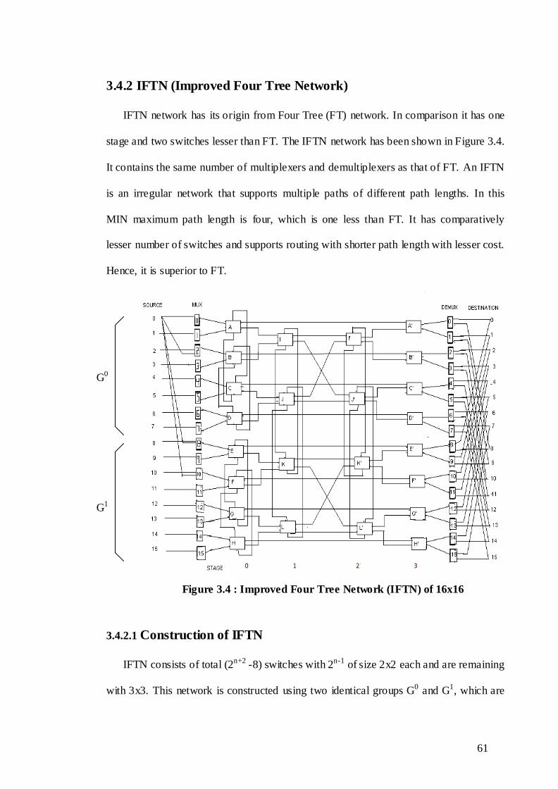
IFTN network has its origin from Four Tree (FT) network. In comparison it has one
stage and two switches lesser than FT. The IFTN network has been shown in Figure 3.4.
It contains the same number of multiplexers and demultiplexers as that of FT. An IFTN
is an irregular network that supports multiple paths of different path lengths. In this
MIN maximum path length is four, which is one less than FT. It has comparatively
lesser number of switches and supports routing with shorter path length with lesser cost.
Hence, it is superior to FT.
Figure 3.4 : Improved Four Tree Network (IFTN) of 16x16
3.4.2.1 Construction of IFTN
IFTN consists of total (2n+2 -8) switches with 2n-1 of size 2x2 each and are remaining
with 3x3. This network is constructed using two identical groups G0 and G1, which are
G0
G1

62
arranged one above the other. The two groups are formed based on the most significant
bit (MSB) of the source destination terminals. Every 3x3 SE (Switching Element) in a
stage forms a loop with the corresponding numbered SE of size 3x3 other sub-network
in the same stage. The source and destination strings in this case are:
S = sn-1 …………s1.s0
D = dn-1 …………d1.d0
The sources and destinations are connected to the multiplexers and demultiplexers
as follows:
a) If (sn-2 …………s1.s0) bits are the same for the two sources, then these two
sources are linked through the same pair of multiplexers.
b) If (dn-2 …………d1.d0) bits are the same for the two destinations, then these two
destinations are linked through the same pair of demultiplexers.
3.4.2.2 Redundancy Graph of IFTN
A redundancy graph for IFTN showing all the available paths between a source
destination pairs has been shown in Figure 3.5. This graph is useful in determining fault
tolerance and rerouting possibilities. It shows paths between two arbitrarily selected
nodes the source, S and the destination, D.
Figure 3.5 : Redundancy Graph of IFTN

63
3.4.2.3 Routing Scheme of IFTN
To route a request through a network there are two possibilities of favourable and
alternative (lesser favourable) paths. Firstly, a path length algorithm is used to
determine whether a request can be routed through the most favourable path or not. If
most favourable path is not available or is busy then there is need of alternat ive path.
3.4.2.3.1 Path Length Algorithm
The possible path lengths between a particular source-destination pair varies from
2 to 2m-1 for a 2n x 2n
network, depending upon the addresses of the source and
destination terminals. For a given source-destination pair, there exist multiple paths
of different lengths in an IFTN network.
The path length algorithm is:
Begin
if
[(sn-2 dn-2) + (sn-3 dn-3) +…………+ (s1 d1)] = 0
( Represents an exclusive-OR and + represents a logical OR operator)
then
Minimum path length is 2 and all paths of different lengths are possible
i.e. paths of length 2, 4, 6….(2m-2) , (2m-1).
else
If
[(sn-2 dn-2) + (sn-3 dn-3) +…………+ (s2 d2)] Is zero
then
All paths of length equal to or greater than 4 are possible
else

64
if
[(sn-2 dn-2) + (sn-3 dn-3) +……+ (sj dj)] Is zero {where 1≤ j≤ (n-2)}
then
All paths of length equal to or greater than 2j are possible.
else
Path of length 2m-1 (i.e. longest path) is possible only.
End
Secondly, after determining the path length the routing tag algorithm explains
the path to be followed in terms of routing tags. The routing tag algorithm is described
in the next section.
3.4.2.3.2 Routing Tag Algorithm
The following routing algorithm for IFTN network is used to generate control tag
which is required to establish a path between any source-destination terminal pair for a
given path length (if it exists).
Begin
if
2≤ x ≤ (2m-1) (where m=log2N/2, N = 2n and x = path-length)
then
Routing tag= 0.d1.dn-1
else
if
x = (2m-1)
then
Routing tag= 1.d2.d1.d0.dn-1

65
else
No tag is possible.
End
3.4.2.3.3 Routing Procedure
This algorithm assumes that sources and switches have the ability to detect faults
in the switches to which they are connected. For any source-destination pair, find the
minimum possible path length and then the corresponding routing tag. The request is
routed as follows:
Initially, the request is submitted for routing via primary path. If the request is
routed through the same group to which the source belongs (i.e. MSB of the source =
group number), then the path is primary otherwise, it is secondary. If the primary path is
faulty (i.e. multiplexer or the switch or both are faulty) then the request is routed
through the secondary path. If the secondary path is also not available or faulty then the
request is drpped. The most significant bit (MSB) of the routing tag, Sn-1 will route the
request through the multiplexer. For each switch in stage i (i < 2m-1)(where m=log2N/2,
N = 2n) request may arrive at any of the three input links. For each request, appropriate
routing tag bits are used to connect to the output link. If the required output link is busy
or cannot be used because of the existence of a fault in the next stage, the request is
routed via the third output link known as auxiliary link to the conjugate switch in the
loop. If the auxiliary link is also unusable, because of being busy or faulty, then the
request is dropped. A fault in the demultiplexer at the output of a switch in a stage (2m -
1) is considered a fault in that switch. From the demultiplexer, the request is routed to
the upper or the lower destinations according to the least significant bit of the tag (i.e.
dn-1).

66
Figure 3.6 : Routing in IFTN
The routing in the IFTN has been illustrated via an example below. Consider the
IFTN with the source as 0000 and the destination as 0100. According to the routing
algorithm the routing tag is 1.1.0.0.0. The possible paths between the selected source
and destination are shown below (the same has been illustrated in Figure 3.6.).
Primary Path: 0 MUX(0) A I J' C' DEMUX(4) 4
0 MUX(2) B I J' C' DEMUX(4) 4
Secondary Path: 0 MUX(8) E K L' G' DEMUX(12) 4
0 MUX(10) F K L' G' DEMUX(12) 4
Alternate Path: 0 MUX(0) A C J J' C' DEMUX(4) 4
Primary Path
Secondary Path
Alternate Path

67
0 MUX(2) B D J J' C' DEMUX(4) 4
0 MUX(8) E G L L' G' DEMUX(12) 4
0 MUX(10) F H L L' G' DEMUX(12) 4
From Figure 3.6 it is evident that there exist eight paths between a given source
and destination pair. However, in FT there exist two paths. Therefore the proposed
network IFTN can entertain more number of requests even under faults in comparison
to FT. Thus IFTN is more fault-tolerant than FT.
3.4.3 IABN (Irregular Augmented Baseline Network)
IABN is a modification of Augmented Baseline Network (ABN) with one more
stage, additional auxiliary links and increased size of demultiplexers. The IABN is a
dynamically re-routable irregular MIN, providing multiple paths of varying lengths
between any two randomly selected source-destination pairs.
3.4.3.1 Construction of IABN
An IABN of size N x N (i.e. N sources and N destinations) has been designed
using two identical groups (G0 and G1), each having N/2 sources and an equal number
of destinations. All the stages excepting the last stage i.e stage 1 to n-1 (where n=log2N)
have 3x3 switches. Only the last stage consists of size 2x2 switches. An IABN of size
16x16 is shown in Figure 3.7. Each source is linked to both the groups via multiplexers.
There is one 4 x 1 MUX for each input link of a switch in stage 1 and one 1x4 DEMUX
for each output link of a switch in stage n-1.

68
Figure 3.7 : Irregular Augmented Baseline Network (IABN) of 16x16
Let the source S and destination D be represented in binary code as:
S=s0, s1,…,sn-2,sn-1
D=d0, d1,…,dn-2,dn-1
The sources are connected to the switches of stage 1 as follows:
(i) Source S is connected to the (s1,…,sn-2 ) primary switch in both the sub-
networks through the multiplexers.
(ii) Source S is also connected to the [{(s1,…,sn-2)+1}mod N/4] secondary
switch in both the sub-networks through the multiplexers.
69
3.4.3.2 Redundancy Graph of IABN
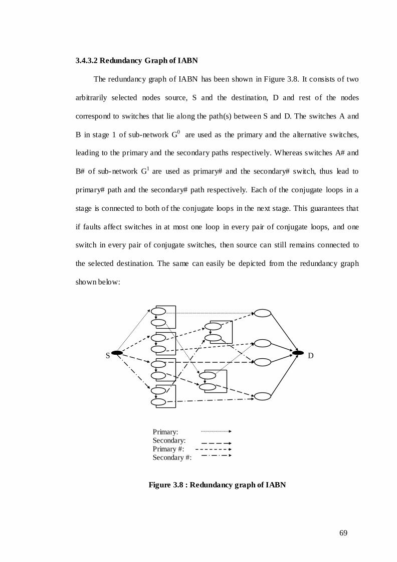
The redundancy graph of IABN has been shown in Figure 3.8. It consists of two
arbitrarily selected nodes source, S and the destination, D and rest of the nodes
correspond to switches that lie along the path(s) between S and D. The switches A and
B in stage 1 of sub-network G0 are used as the primary and the alternative switches,
leading to the primary and the secondary paths respectively. Whereas switches A# and
B# of sub-network G1 are used as primary# and the secondary# switch, thus lead to
primary# path and the secondary# path respectively. Each of the conjugate loops in a
stage is connected to both of the conjugate loops in the next stage. This guarantees that
if faults affect switches in at most one loop in every pair of conjugate loops, and one
switch in every pair of conjugate switches, then source can still remains connected to
the selected destination. The same can easily be depicted from the redundancy graph
shown below:
S D
Figure 3.8 : Redundancy graph of IABN
Primary: Secondary: Primary #: Secondary #:
70
3.4.3.3 Routing Scheme of IABN
This section presents the routing scheme of IABN. Following procedure is used to
route a request from given source S to the required destination D.
1) For each source: The source S selects one of the sub-network Gi based on the
most significant bit of the destination D (i=d0). In one sub-network there exist
two paths primary and secondary between each source-destination pair. Each
source attempts entry into its primary sub-network via its primary path. If the
primary path is faulty (i.e. either MUX or primary switch or both are faulty),
then the request is routed to secondary path. If the secondary path is also faulty
then the request is routed to the other sub-network via auxiliary links of stage 2.
If still request cannot get matured, then the request is rerouted to the secondary
sub-network, in which same routing is followed.
2) For each switch in stage n - 3: the routing of the request through stage n-3 of
the sub-network depends on one tag bit, which is evaluated from d1d2 bits of
destination address as follows:
If d1d2 = 00
then both conjugate pairs in the sub-network will have tag bit = 0
If d1d2 = 01
then first conjugate pair (A/A#, B/B#) will have tag bit = 1, and
Second conjugate pair (C/C#, D/D#) will have tag bit = 0.
If d1d2 = 10
then both conjugate pairs in the sub-network will have tag bit = 1.
If d1d2 = 11
then first conjugate pair (A/A#, B/B#) will have tag bit = 0, and
Second conjugate pair (C/C#, D/D#) will have tag bit = 1.

71
Use tag bit and route the request through the output link, if it is busy or if
the successor switch (in the next stage) is faulty, route the request via the
auxiliary output links to the other switch in the loop with the same tag bit.
If the auxiliary link is also unusable (busy or faulty), then try secondary
path. If secondary path also have some fault, then try using auxiliary links.
If the request can not be handled by the primary sub-network then apply
the same procedure for secondary sub-network. If all the possible paths in
secondary sub-network also fail, then drop the request.
3) For each switch in stage n - 2: To route a request through at a switch in stage
n-2, value of tag bit is evaluated as follows:
If d1d2 = 00
then both conjugate pair (E/E#) and (F/F#) will have tag bit = 0
If d1d2 = 01
then first conjugate pair (E/E#) will have tag bit = 1, and
second conjugate pair (F/F#) will have tag bit = 0
If d1d2 = 10
then both conjugate pair switches will have tag bit = 1
If d1d2 = 11
then first conjugate pair(E/E#) will have tag bit = 0, and
second conjugate pair (F/F#) of stage 2 will have tag bit = 1
Use tag bit and route the request through the usual output link, if it is
busy or if the successor switch (in the next stage) is faulty, route the request via
the auxiliary output links to the other switch in the loop with the same tag bit. If
the auxiliary link is also unusable because it is busy or because of a fault, then
72
try secondary path. If secondary path also have some fault, then try using
auxiliary links. If all the possible paths in primary sub network fail, then use the
same tag bit and above procedure in secondary sub-network. If all the possible
paths (including auxiliary links) in secondary sub-network also fail, then drop
the request.
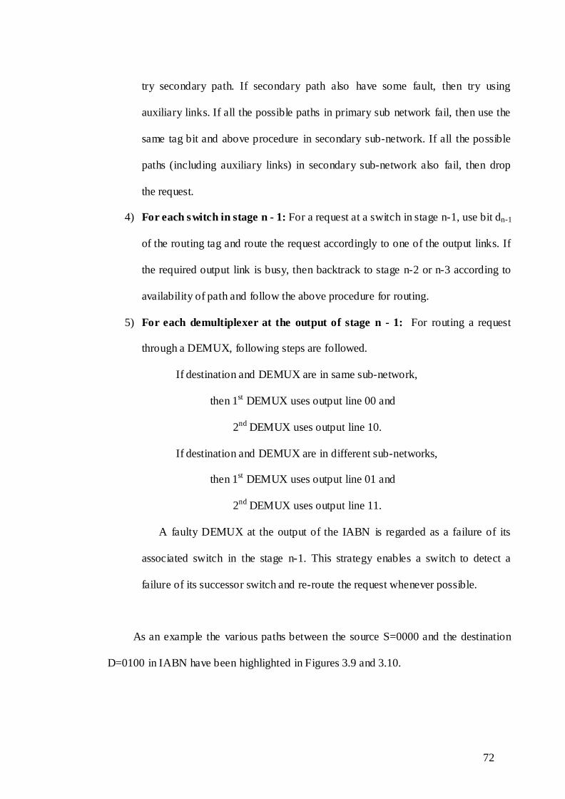
4) For each switch in stage n - 1: For a request at a switch in stage n-1, use bit dn-1
of the routing tag and route the request accordingly to one of the output links. If
the required output link is busy, then backtrack to stage n-2 or n-3 according to
availability of path and follow the above procedure for routing.
5) For each demultiplexer at the output of stage n - 1: For routing a request
through a DEMUX, following steps are followed.
If destination and DEMUX are in same sub-network,
then 1st DEMUX uses output line 00 and
2nd DEMUX uses output line 10.
If destination and DEMUX are in different sub-networks,
then 1st DEMUX uses output line 01 and
2nd DEMUX uses output line 11.
A faulty DEMUX at the output of the IABN is regarded as a failure of its
associated switch in the stage n-1. This strategy enables a switch to detect a
failure of its successor switch and re-route the request whenever possible.
As an example the various paths between the source S=0000 and the destination
D=0100 in IABN have been highlighted in Figures 3.9 and 3.10.

73
Figure 3.9 : Routing in IABN (on request entry via primary sub-network)
The possible paths between (0,4) source-destination pairs when the request enters
through the primary sub-network have been depicted below.
Primary paths
0 MUX(0) A E C1 DEMUX (4) 4
0 MUX(0) A C F D1 DEMUX (6) 4
Primary paths using auxiliary links of stage 2
0 MUX(0) A E E# C1# DEMUX(12) 4
0 MUX(0) A C F F# D1# DEMUX (14) 4
Secondary paths
0 MUX(2) B C1 DEMUX(4) 4
0 MUX(2) B D D1 DEMUX(6) 4
Secondary paths using switches and auxiliary links of stage 2

74
0 MUX(2) B E C1 DEMUX (4) 4
0 MUX(2) B D F D1 DEMUX(6) 4
0 MUX(2) B E E# C1# DEMUX(12) 4
0 MUX (2) B D F F# D1# DEMUX(14) 4
Following paths are possible between (0,4) source-destination pair when the
request enters through the secondary sub-network as shown in Figure 3.10.
Primary# paths
0MUX(8) A# E# C1# DEMUX(12) 4
0 MUX(8) A# C# F# D1# DEMUX(14) 4
Primary# paths using auxiliary links of stage 2
0 MUX(8) A# E# E C1 DEMUX(4) 4
0 MUX(8) A# C# F# F D1 DEMUX(6) 4
Secondary# paths
0->MUX (10) B#->C1#->DEMUX(12) ->4
0 MUX(10) B# D# D1# DEMUX(14) 4
Secondary paths using switches and auxiliary links of stage 2
0 MUX(10) B# E#->C1# DEMUX(12) 4
0 MUX(10) B# D# F# D1# DEMUX(14) 4
0 MUX(10) B# E# E C1 DEMUX(4) 4
0 MUX(10) B# D# F# FD1 DEMUX(6) 4

75
Figure 3.10 : Routing in IABN (on request entry via secondary sub-network)
From Figures 3.9 and 3.10 it can be seen that there exist ten paths between a given
pair of source and destination, when the request enters either through G0 or G1 sub-
networks. Therefore, there will be twenty paths in total between each source-destination
pair (ten from G0 and ten from G1). However, in ABN there exist four paths through
one sub-network and eight paths in total between a given source-destination pair.
Therefore the proposed network IABN can entertain more number of requests even
under faults in comparison to ABN. Hence, IABN is more fault-tolerant than ABN.
3.5 Cost Analysis of Proposed and Related Networks
In this section the existing and proposed MINs are compared on the basis of the
interconnection cost. To estimate the cost of a network it has been assumed that the cost
of a switch is proportional to the number of cross-points within a switch. For example a

76
4x4 switch has 16 units of hardware cost whereas, a 2x2 switch has 4 units. The cost
functions for the proposed and existing MINs have been depicted in Table 3.1. The
values of these cost functions for varying network sizes have been shown in Table 3.2.
In order to clearly represent this comparison corresponding graphs have been shown in
Figures 3.11, 3.12 and 3.13.
Table 3.1 : Cost Functions for MINs
MIN Cost Function
ASEN-2 3N(1.5log2N -1)
IASEN 3N(1.5 log2N) –9N/4+2N
FT (9.75 2n+1-54)
IFTN (9.75 2n+1-9N)
ABN N/2(9n-11)
IABN N/2(3log2N+13)+2N+9N/4
Table 3.2 : Cost of networks for different network sizes
Network
Size
(LogN)
Log of Cost
ASEN-2 IASEN FT IFTN ABN IABN
4 2.380211 2.372912 2.41162 2.056905 2.30103 2.428135
5 2.795185 2.789581 2.755875 2.450249 2.651278 2.766413
6 3.186391 3.181844 3.077004 2.790988 2.996512 3.101747
7 3.562055 3.558228 3.387746 3.11059 3.337659 3.434569
8 3.926754 3.923451 3.693551 3.420616 3.675412 3.765221
9 4.283301 4.280396 3.996949 3.726075 4.0103 4.093982
10 4.633549 4.630957 4.29959 4.029303 4.342738 4.421077

77
Figure 3.11 : Cost Comparison of ASEN-2 and IASEN
Figure 3.12 : Cost Comparison of FT and IFTN
Figure 3.13 : Cost Comparison of ABN and IABN
78
Log Cost Vs LogN
1.5
2
2.5
3
3.5
4
4.5
5
4 5 6 7 8 9 10
LogN
Lo
g C
ost
ASEN-2
IASEN
FT
IFT
ABN
IABN
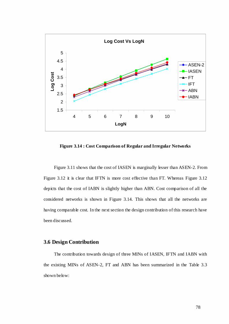
Figure 3.14 : Cost Comparison of Regular and Irregular Networks
Figure 3.11 shows that the cost of IASEN is marginally lesser than ASEN-2. From
Figure 3.12 it is clear that IFTN is more cost effective than FT. Whereas Figure 3.12
depicts that the cost of IABN is slightly higher than ABN. Cost comparison of all the
considered networks is shown in Figure 3.14. This shows that all the networks are
having comparable cost. In the next section the design contribution of this research have
been discussed.
3.6 Design Contribution
The contribution towards design of three MINs of IASEN, IFTN and IABN with
the existing MINs of ASEN-2, FT and ABN has been summarized in the Table 3.3
shown below:

79
Table 3.3 : Contribution Towards Design
Networks Topology
Number
of paths
Fault-tolerance Cost
1.
ASEN-2
(Existing) Regular 4
IASEN is more
fault-tolerant than
ASEN-2
Cost of IASEN is
marginally lesser
than ASEN-2
IASEN
(Proposed)
Irregular 8
2.
FT
(Existing) Irregular 2
IFTN is more
fault-tolerant than
FT
Cost of IFTN is
considerably lesser
than FT
IFTN
(Proposed)
Irregular 8
3.
ABN
(Existing) Regular 8
IABN is more
fault-tolerant than
ABN
Cost of IABN is
slightly more than
ABN
IABN
(Proposed)
Irregular 20
3.7 Chapter Summary
Three new irregular MINs namely, IASEN, IFTN and IABN have been designed
and analyzed on the basis of number of paths, fault-tolerance, routing and cost of
interconnection.
In case of the newly designed IASEN there are eight paths between any of the
source-destination pairs in comparison to ASEN-2 supporting four paths. IASEN is
more fault-tolerant than ASEN-2 and Cost of IASEN is marginally lesser than ASEN-2

80
Also the proposed network IFTN facilitates six more paths than FT. IFTN is more
fault-tolerant than FT and Cost of IFTN is considerably lesser than FT.
IABN‟s topology two benefits. Firstly, the network is single switch fault-tolerant.
Secondly, it provides on-line repair and maintainability, allowing removal of any stage
in IABN without disrupting the entire operation of the network. The sub-networks in the
formation of the IABN are identical, i.e., the mirror image of each other (G0 and G1),
making the implementation of the network simpler. Besides, the significant advantage
of the designed IABN is that it provides twenty distinct paths between any of the
source-destination pairs, which is much more than the eight paths being provided by its
regular counterpart of ABN.
In summary all the three proposed networks provide better fault-tolerance at
comparable cost than the existing ones.
In the next chapter permutation passibility behavior of existing networks (ASEN-
2, FT and ABN) and proposed networks (IASEN, IFTN and IABN) has been presented.
Research Papers from this Chapter
[1] Aggarwal, Rinkle; and Kaur, Lakhwinder (2008), “Design and Bandwidth
Analysis of Fault-tolerant Multistage Interconnection Networks”, Journal of
Computer Science”, 4(11), pp. 962-965.
[2] Aggarwal, Rinkle; and Kaur, Lakhwinder (2009), “Design and Reliability
Analysis of a New Fault-tolerant Multistage Interconnection Network”,
International Journal of Computer Networks and Internet Research, 8(2), pp.
17-23.

81
[3] Aggarwal, Rinkle., and Kaur, Lakhwinder (2009), “An efficient Routing
Scheme to provide more Fault-tolerance for an Irregular Multistage
Interconnection Network”, In: Proceedings of IEEE International Advance
Computing Conference IACC-09, 6-7 March, pp. 94-98.
[4] Aggarwal, Rinkle, and Kaur, Lakhwinder (2010), “Design and Reliability
Analysis of a class of irregular Fault-tolerant Multistage Interconnection
Networks”, 5th International Conference on Information Systems, Technology
and Management (ICISTM-2010), Conference proceedings to be published in
Springer Series in Communications in Computer and Information Science
(CCIS). [Communicated]


![EnergyEfficiencyAdaptationforMultihopRoutingin ...downloads.hindawi.com/journals/jcnc/2012/767920.pdfnetwork,wetakeintoconsiderationthehardware(orcircuit) energy consumption [8]](https://img.pdfslide.us/doc/110x75/5ac842097f8b9a40728c98d9/energyefciencyadaptationformultihoproutingin-wetakeintoconsiderationthehardwareorcircuit.jpg)