Embed Size (px)
Citation preview
Confidential
RFV01U-D2A Installation Manual v2.0 53 Copyright © 2017, All Rights Reserved.
Chapter 3 Connecting Cables
This chapter describes the procedures to connect the cables to the system and to label the cables.
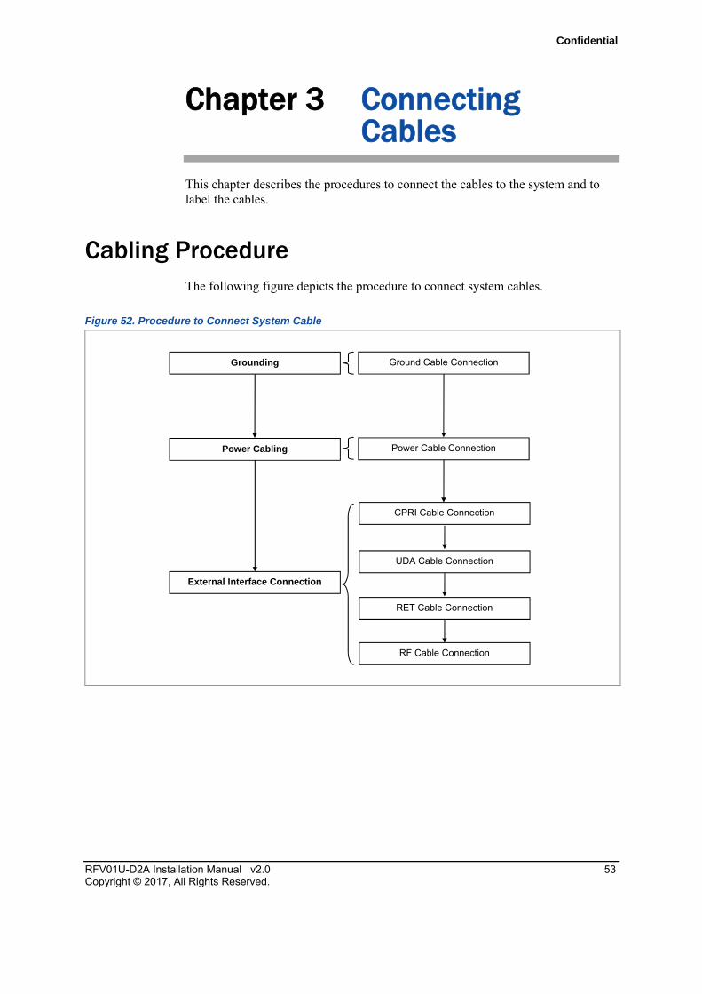
Cabling Procedure The following figure depicts the procedure to connect system cables.
Figure 52. Procedure to Connect System Cable
Grounding
Power Cabling
Ground Cable Connection
External Interface Connection
CPRI Cable Connection
RET Cable Connection
Power Cable Connection
RF Cable Connection
UDA Cable Connection
Confidential
Chapter 3 Connecting Cables
RFV01U-D2A Installation Manual v2.0 54 Copyright © 2017, All Rights Reserved.
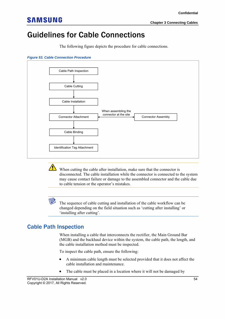
Guidelines for Cable Connections The following figure depicts the procedure for cable connections.
Figure 53. Cable Connection Procedure
When cutting the cable after installation, make sure that the connector is disconnected. The cable installation while the connector is connected to the system may cause contact failure or damage to the assembled connector and the cable due to cable tension or the operator’s mistakes.
The sequence of cable cutting and installation of the cable workflow can be changed depending on the field situation such as ‘cutting after installing’ or ‘installing after cutting’.
Cable Path Inspection When installing a cable that interconnects the rectifier, the Main Ground Bar (MGB) and the backhaul device within the system, the cable path, the length, and the cable installation method must be inspected.
To inspect the cable path, ensure the following:
A minimum cable length must be selected provided that it does not affect the cable installation and maintenance.
The cable must be placed in a location where it will not be damaged by
Cable Installation
Connector Attachment
Identification Tag Attachment
Connector Assembly
When assembling the connector at the site
Cable Path Inspection
Cable Cutting
Cable Binding
Confidential
Chapter 3 Connecting Cables
RFV01U-D2A Installation Manual v2.0 55 Copyright © 2017, All Rights Reserved.
external factors such as power line, flooding, and footpaths.
In areas where the cable may be damaged by external factors, ensure that measures are taken to prevent damage to the cable such as cable tray, ducts, and flexible pipe.
Cable Cutting Measure the exact distance after carefully checking the route, and cut the cable using a cutting tool.
To cut the cable, ensure the following:
Cut the cable to the length determined in the Cable Path Inspection step.
Use a dedicated cable-cutting tool.
Cut the cable at right angles.
Be careful to keep the cable away from any moisture, iron, lead, dust, or other foreign material when cutting.
Remove any foreign material attached to the cable using solvent and a brush.
Cable Installation Cable installation involves running the cable along the cabling path to the target connector of the system or an auxiliary device. This is done after cable path inspection and cable cutting are completed.
To install the cable, ensure the following:
Be careful not to damage the cable.
If the cable is damaged, cut out the damaged section before installing, or replace the cable.
Run the cable so that it is not tangled. In particular, when installing a cable from a horizontal section to a vertical section, be careful not to reverse the upper and lower lines of the cable.
Always use the maximum curvature radius possible, and ensure that the minimum curvature radius specification is complied with.
If the cable needs to be protected, use a suitable protective cover. For example, a PVC channel, spiral sleeve, flexible pipe, and cable rack.
Install the DC power cable and the data transmission cable away from the AC power cable to prevent electromagnetic induction.
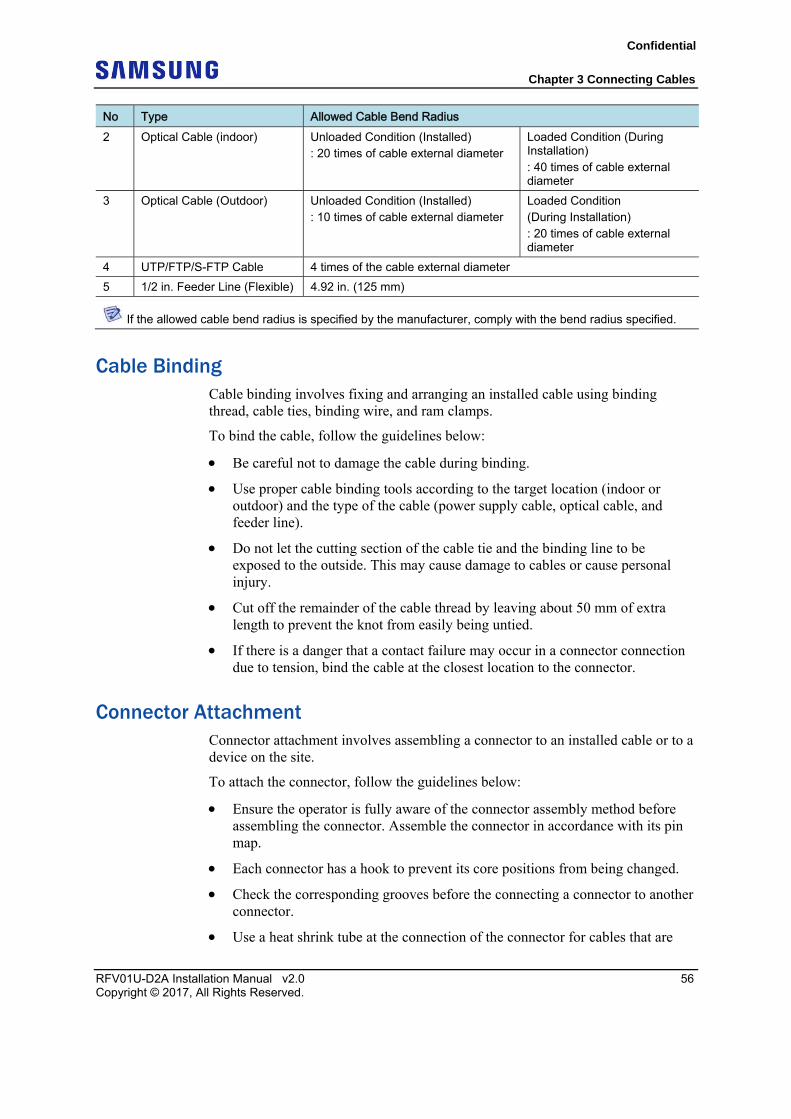
The following table details the recommended minimum allowed cable bend radius of different types of cables.
Table 19. Recommended Minimum Allowed Cable bend Radius
No Type Allowed Cable Bend Radius 1 Ground/Power Cable 8 times of the cable external diameter
Confidential
Chapter 3 Connecting Cables
RFV01U-D2A Installation Manual v2.0 56 Copyright © 2017, All Rights Reserved.
No Type Allowed Cable Bend Radius 2 Optical Cable (indoor) Unloaded Condition (Installed)
: 20 times of cable external diameter Loaded Condition (During Installation) : 40 times of cable external diameter
3 Optical Cable (Outdoor) Unloaded Condition (Installed) : 10 times of cable external diameter
Loaded Condition (During Installation) : 20 times of cable external diameter
4 UTP/FTP/S-FTP Cable 4 times of the cable external diameter
5 1/2 in. Feeder Line (Flexible) 4.92 in. (125 mm)
If the allowed cable bend radius is specified by the manufacturer, comply with the bend radius specified.
Cable Binding Cable binding involves fixing and arranging an installed cable using binding thread, cable ties, binding wire, and ram clamps.
To bind the cable, follow the guidelines below:
Be careful not to damage the cable during binding.
Use proper cable binding tools according to the target location (indoor or outdoor) and the type of the cable (power supply cable, optical cable, and feeder line).
Do not let the cutting section of the cable tie and the binding line to be exposed to the outside. This may cause damage to cables or cause personal injury.
Cut off the remainder of the cable thread by leaving about 50 mm of extra length to prevent the knot from easily being untied.
If there is a danger that a contact failure may occur in a connector connection due to tension, bind the cable at the closest location to the connector.
Connector Attachment Connector attachment involves assembling a connector to an installed cable or to a device on the site.
To attach the connector, follow the guidelines below:
Ensure the operator is fully aware of the connector assembly method before assembling the connector. Assemble the connector in accordance with its pin map.
Each connector has a hook to prevent its core positions from being changed.
Check the corresponding grooves before the connecting a connector to another connector.
Use a heat shrink tube at the connection of the connector for cables that are
Confidential
Chapter 3 Connecting Cables
RFV01U-D2A Installation Manual v2.0 57 Copyright © 2017, All Rights Reserved.
installed outdoor, such as feeder lines, to prevent water leakage and corrosion from occurring at the part exposed to the outside.
Connect each cable of the connector assembly in a straight line.
Be careful when connecting the cable so that the contact failure does not occur at the connection of the connector due to tension.
Identification Tag Attachment Identification tag attachment involves attaching a marker cable tie, nameplate, and label at both ends of the cable (connections to a connector) to identify its use and cabling path.
To attach an identification tag, follow the guidelines below:
When installing the cable outdoor, use relief engraving and coated labels, and so on to prevent the markings from being erased.
Since the form and attachment method for identification tags are different for each provider, consult with the provider before attaching them.
When connecting the cables, always connect the ground cable first. If a worker contacts the equipment, connects the cable, or performs maintenance without connecting the ground cable, the system can be damaged or the worker may be injured due to static electricity or short circuit.
When performing cable work for the system, proceed with the ground work before any other work to prevent errors occurring due to static electricity or other reasons.
After completing cable installation, unused ports should be capped.
When installing, take care not to overlap or tangle the cables; also, consider future expansion. Install the DC power cable and data transmission cable away from the AC power cable to prevent electromagnetic induction.
Make sure the work is done by trained personnel.
Confidential
Chapter 3 Connecting Cables
RFV01U-D2A Installation Manual v2.0 58 Copyright © 2017, All Rights Reserved.
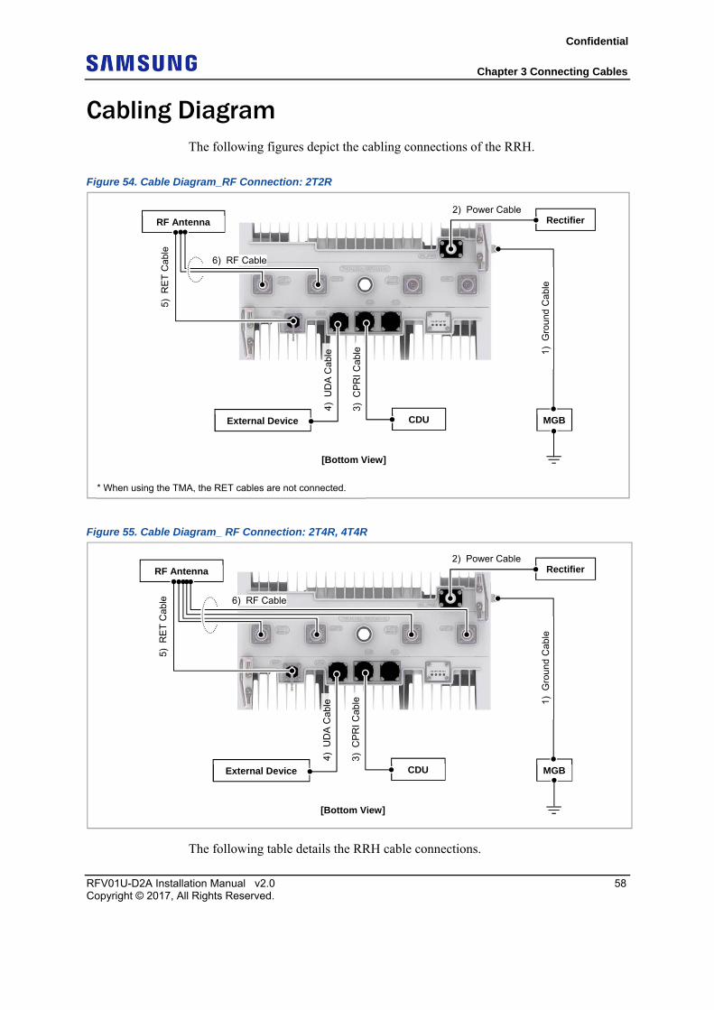
Cabling Diagram The following figures depict the cabling connections of the RRH.
Figure 54. Cable Diagram_RF Connection: 2T2R
Figure 55. Cable Diagram_ RF Connection: 2T4R, 4T4R
The following table details the RRH cable connections.
RF Antenna Rectifier
6) RF Cable
MGB External Device
1) G
roun
d C
able
3) C
PR
I C
able
4) U
DA
Cab
le
CDU
5) R
ET
Cab
le
2) Power Cable
[Bottom View]
* When using the TMA, the RET cables are not connected.
RF Antenna Rectifier
6) RF Cable
MGB External Device
1) G
roun
d C
able
3) C
PR
I C
able
4) U
DA
Cab
le
CDU
5) R
ET
Cab
le
2) Power Cable
[Bottom View]
Confidential
Chapter 3 Connecting Cables
RFV01U-D2A Installation Manual v2.0 59 Copyright © 2017, All Rights Reserved.
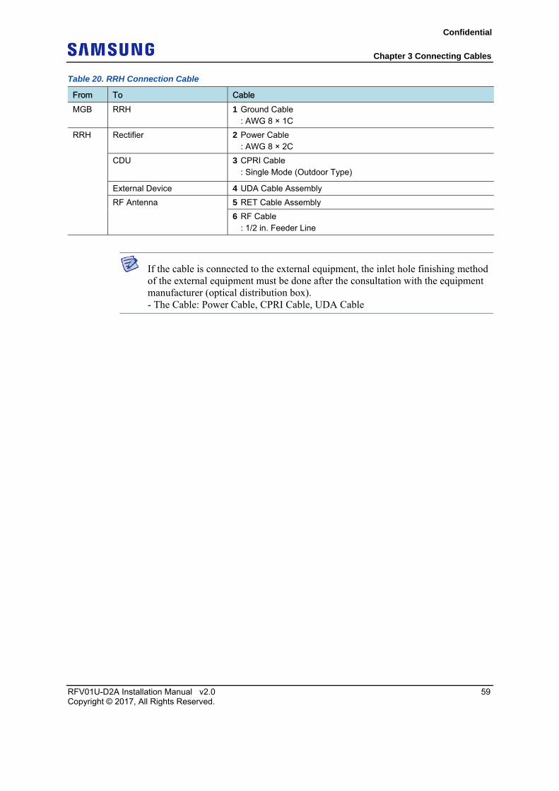
Table 20. RRH Connection Cable
From To Cable MGB RRH 1 Ground Cable
: AWG 8 × 1C
RRH Rectifier 2 Power Cable : AWG 8 × 2C
CDU 3 CPRI Cable : Single Mode (Outdoor Type)
External Device 4 UDA Cable Assembly
RF Antenna 5 RET Cable Assembly
6 RF Cable : 1/2 in. Feeder Line
If the cable is connected to the external equipment, the inlet hole finishing method of the external equipment must be done after the consultation with the equipment manufacturer (optical distribution box). - The Cable: Power Cable, CPRI Cable, UDA Cable
Confidential
Chapter 3 Connecting Cables
RFV01U-D2A Installation Manual v2.0 60 Copyright © 2017, All Rights Reserved.
Grounding Grounding is the process of operating an electronic system (for example, power supplying system, communication system, and control system) stably from a lightning, transient-current, transient-voltage, and electric noise and of preventing injury from electric shock.
Ground equipment minimizes the electrical potential of the electronic device to that of the ground, which is zero electrical potential, so that it can prevent the device from occurring electrification.
Connect the ground cable first. In cabling, the connection of cables without the connection to the ground cable may cause damage of the equipment or bodily injury to personnel.
The purposes of the ground construction are as follows:
To prevent human life and the system from over-current, over-voltage, and lightning.
To provide a discharge path for surge voltage generated by lightning and power switch.
To protect the system from static electricity.
To eliminate or minimize the high-frequency potential in the system housing.
To provide a conductor for the balance and stability of high-frequency current.
To stabilize the potential of the circuit against the ground.
Connecting Ground Cable To connect the ground cable, do the following:
1 Make sure you have the following items:
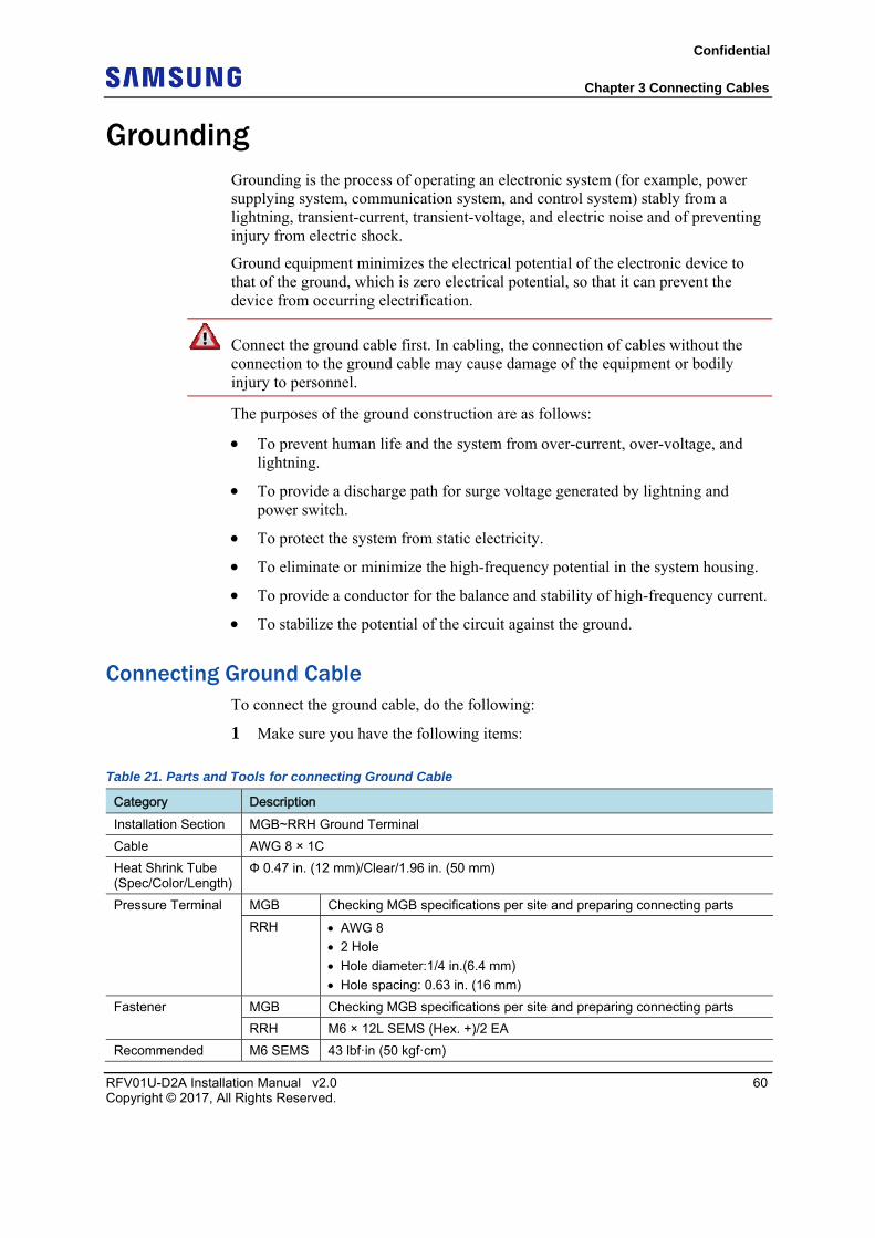
Table 21. Parts and Tools for connecting Ground Cable
Category Description Installation Section MGB~RRH Ground Terminal
Cable AWG 8 × 1C
Heat Shrink Tube (Spec/Color/Length)
Ф 0.47 in. (12 mm)/Clear/1.96 in. (50 mm)
Pressure Terminal MGB Checking MGB specifications per site and preparing connecting parts
RRH AWG 8
2 Hole
Hole diameter:1/4 in.(6.4 mm)
Hole spacing: 0.63 in. (16 mm)
Fastener MGB Checking MGB specifications per site and preparing connecting parts
RRH M6 × 12L SEMS (Hex. +)/2 EA
Recommended M6 SEMS 43 lbf·in (50 kgf·cm)
Confidential
Chapter 3 Connecting Cables
RFV01U-D2A Installation Manual v2.0 61 Copyright © 2017, All Rights Reserved.
Category Description Torque Value
Working Tools Cable Cutter
Wire Stripper
Crimping tool
Heating Gun
Nipper
Screw Driver (‘+’, No. 3)
Torque Driver (20 to 90 lbf·in.)
Screw Driver Bit (‘+’, No. 3)
For the pressure terminal of the cable, the UL listed products or equivalent should be used. For example, Manufacturer-Panduit RRH: AWG8 Pressure Terminal (LCD8-14A-L)
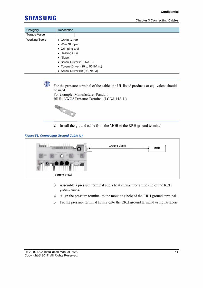
2 Install the ground cable from the MGB to the RRH ground terminal.
Figure 56. Connecting Ground Cable (1)
3 Assemble a pressure terminal and a heat shrink tube at the end of the RRH ground cable.
4 Align the pressure terminal to the mounting hole of the RRH ground terminal.
5 Fix the pressure terminal firmly onto the RRH ground terminal using fasteners.
[Bottom View]
MGB Ground Cable
Confidential
Chapter 3 Connecting Cables
RFV01U-D2A Installation Manual v2.0 62 Copyright © 2017, All Rights Reserved.
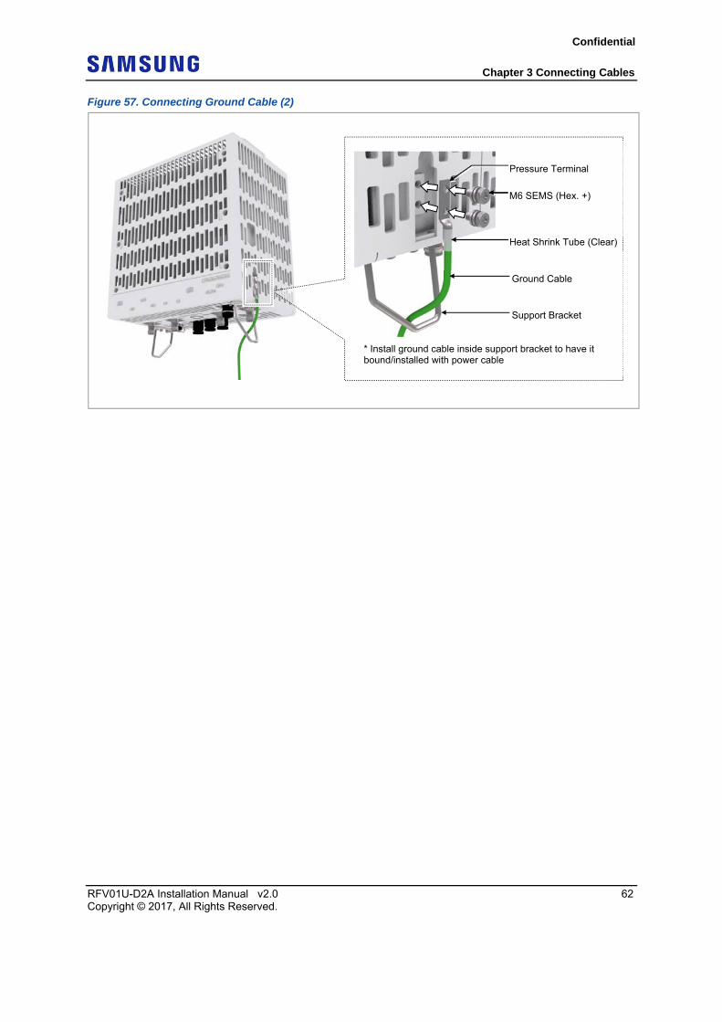
Figure 57. Connecting Ground Cable (2)
Ground Cable
Heat Shrink Tube (Clear)
Pressure Terminal
M6 SEMS (Hex. +)
* Install ground cable inside support bracket to have it bound/installed with power cable
Support Bracket
Confidential
Chapter 3 Connecting Cables
RFV01U-D2A Installation Manual v2.0 63 Copyright © 2017, All Rights Reserved.
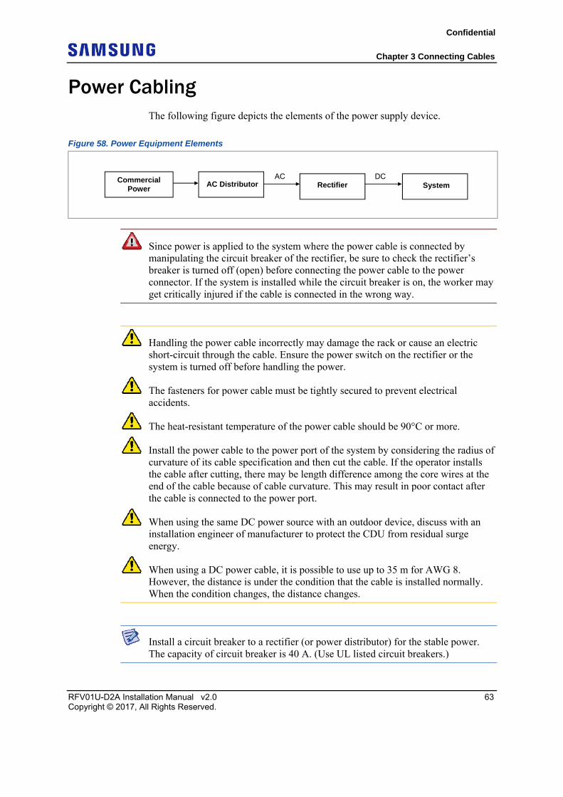
Power Cabling The following figure depicts the elements of the power supply device.
Figure 58. Power Equipment Elements
Since power is applied to the system where the power cable is connected by manipulating the circuit breaker of the rectifier, be sure to check the rectifier’s breaker is turned off (open) before connecting the power cable to the power connector. If the system is installed while the circuit breaker is on, the worker may get critically injured if the cable is connected in the wrong way.
Handling the power cable incorrectly may damage the rack or cause an electric short-circuit through the cable. Ensure the power switch on the rectifier or the system is turned off before handling the power.
The fasteners for power cable must be tightly secured to prevent electrical accidents.
The heat-resistant temperature of the power cable should be 90°C or more.
Install the power cable to the power port of the system by considering the radius of curvature of its cable specification and then cut the cable. If the operator installs the cable after cutting, there may be length difference among the core wires at the end of the cable because of cable curvature. This may result in poor contact after the cable is connected to the power port.
When using the same DC power source with an outdoor device, discuss with an installation engineer of manufacturer to protect the CDU from residual surge energy.
When using a DC power cable, it is possible to use up to 35 m for AWG 8. However, the distance is under the condition that the cable is installed normally. When the condition changes, the distance changes.
Install a circuit breaker to a rectifier (or power distributor) for the stable power. The capacity of circuit breaker is 40 A. (Use UL listed circuit breakers.)
Commercial Power
AC DC AC Distributor Rectifier System
Confidential
Chapter 3 Connecting Cables
RFV01U-D2A Installation Manual v2.0 64 Copyright © 2017, All Rights Reserved.
Connecting Power Cable To connect the power cable, do the following:
1 Make sure you have the following items:
Table 22. Parts and Tools for connecting Power Cable
Category Description Installation Section
Rectifier~RRH Power Input Port
Cable AWG 8 × 2C (The color of the core wire can be changed according to the specification of the cable used.)
Connector Rectifier Check specifications of rectifier output terminal per site and prepare fasteners.
RRH JONHON
Push Pull Type
CT48J-1502TSCBM-07 to open
Working Tools Cable Cutter
Wire Stripper
Compressor
Heating Gun
Nipper
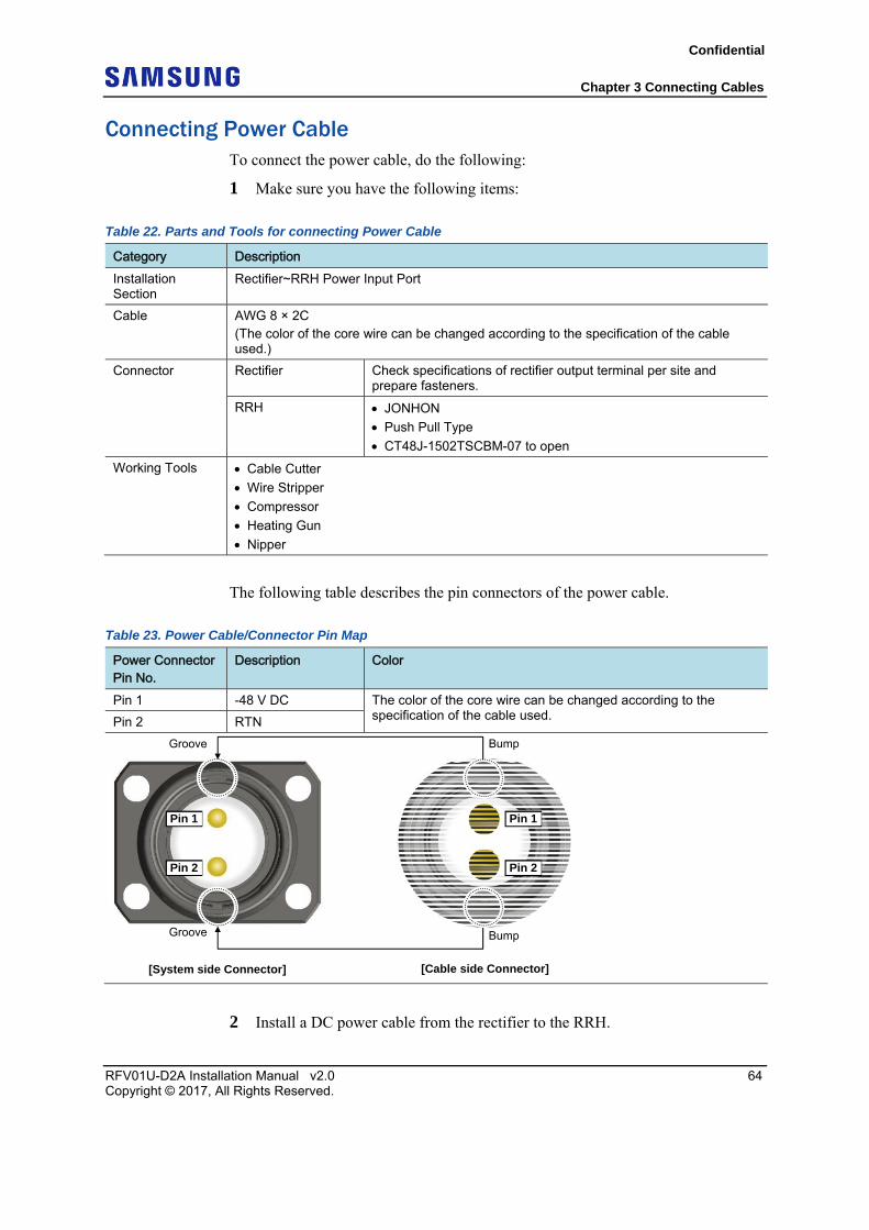
The following table describes the pin connectors of the power cable.
Table 23. Power Cable/Connector Pin Map
Power Connector Pin No.
Description Color
Pin 1 -48 V DC The color of the core wire can be changed according to the specification of the cable used. Pin 2 RTN
2 Install a DC power cable from the rectifier to the RRH.
[Cable side Connector] [System side Connector]
Bump Groove
Bump Groove
Pin 1
Pin 2
Pin 1
Pin 2
Confidential
Chapter 3 Connecting Cables
RFV01U-D2A Installation Manual v2.0 65 Copyright © 2017, All Rights Reserved.
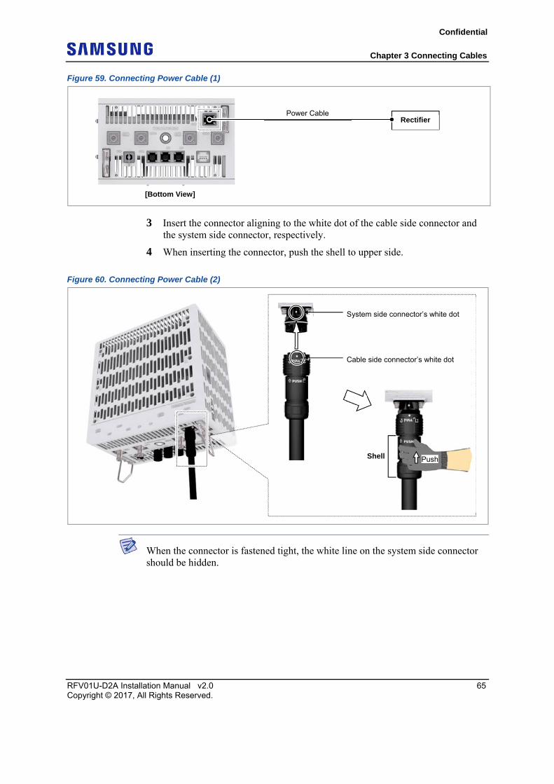
Figure 59. Connecting Power Cable (1)
3 Insert the connector aligning to the white dot of the cable side connector and the system side connector, respectively.
4 When inserting the connector, push the shell to upper side.
Figure 60. Connecting Power Cable (2)
When the connector is fastened tight, the white line on the system side connector should be hidden.
[Bottom View]
Rectifier Power Cable
System side connector’s white dot
Cable side connector’s white dot
Shell Push
Confidential
Chapter 3 Connecting Cables
RFV01U-D2A Installation Manual v2.0 66 Copyright © 2017, All Rights Reserved.
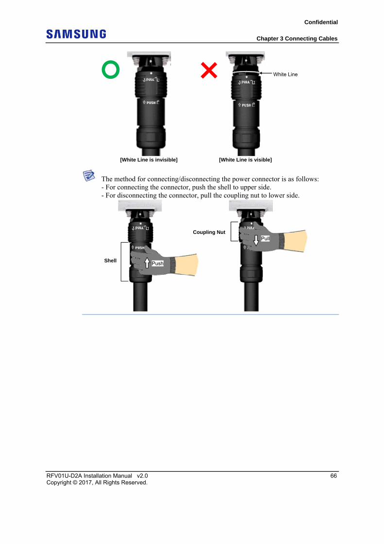
The method for connecting/disconnecting the power connector is as follows: - For connecting the connector, push the shell to upper side. - For disconnecting the connector, pull the coupling nut to lower side.
White Line
[White Line is invisible] [White Line is visible]
Shell
Coupling Nut
Push
Pull
Confidential
Chapter 3 Connecting Cables
RFV01U-D2A Installation Manual v2.0 67 Copyright © 2017, All Rights Reserved.
Interface Cable Connection This section describes the procedures for connecting interface cables.
Remove/Insert Optical Module If the optical module needs to be removed or inserted before connecting the cable, follow the process below.
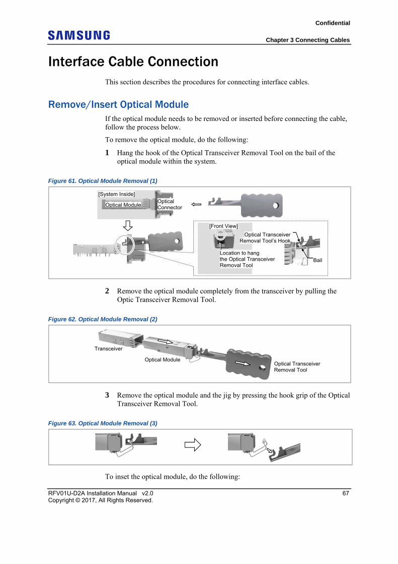
To remove the optical module, do the following:
1 Hang the hook of the Optical Transceiver Removal Tool on the bail of the optical module within the system.
Figure 61. Optical Module Removal (1)
2 Remove the optical module completely from the transceiver by pulling the Optic Transceiver Removal Tool.
Figure 62. Optical Module Removal (2)
3 Remove the optical module and the jig by pressing the hook grip of the Optical Transceiver Removal Tool.
Figure 63. Optical Module Removal (3)
To inset the optical module, do the following:
Optical ConnectorOptical Module
[System Inside]
Optical TransceiverRemoval Tool’s Hook
Bail
[Front View]
Location to hang the Optical Transceiver Removal Tool
Optical Transceiver Removal Tool
Optical Module
Transceiver
Confidential
Chapter 3 Connecting Cables
RFV01U-D2A Installation Manual v2.0 68 Copyright © 2017, All Rights Reserved.
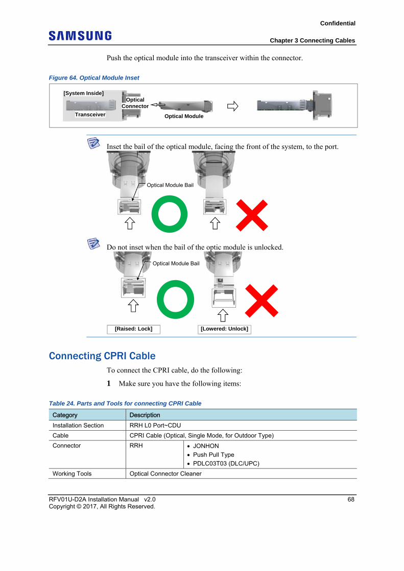
Push the optical module into the transceiver within the connector.
Figure 64. Optical Module Inset
Inset the bail of the optical module, facing the front of the system, to the port.
Do not inset when the bail of the optic module is unlocked.
Connecting CPRI Cable To connect the CPRI cable, do the following:
1 Make sure you have the following items:
Table 24. Parts and Tools for connecting CPRI Cable
Category Description Installation Section RRH L0 Port~CDU
Cable CPRI Cable (Optical, Single Mode, for Outdoor Type)
Connector RRH JONHON
Push Pull Type
PDLC03T03 (DLC/UPC)
Working Tools Optical Connector Cleaner
[System Inside]
Transceiver Optical Module
Optical Connector
Optical Module Bail
Optical Module Bail
[Raised: Lock] [Lowered: Unlock]
Confidential
Chapter 3 Connecting Cables
RFV01U-D2A Installation Manual v2.0 69 Copyright © 2017, All Rights Reserved.
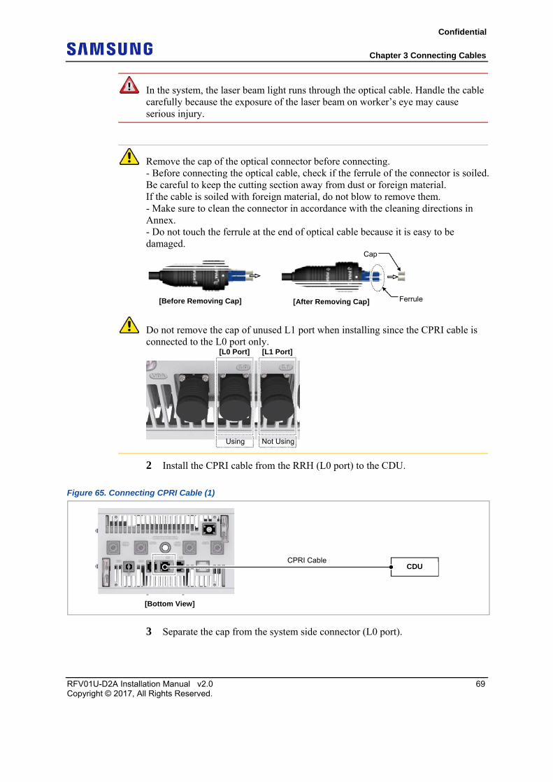
In the system, the laser beam light runs through the optical cable. Handle the cable carefully because the exposure of the laser beam on worker’s eye may cause serious injury.
Remove the cap of the optical connector before connecting. - Before connecting the optical cable, check if the ferrule of the connector is soiled. Be careful to keep the cutting section away from dust or foreign material. If the cable is soiled with foreign material, do not blow to remove them. - Make sure to clean the connector in accordance with the cleaning directions in Annex. - Do not touch the ferrule at the end of optical cable because it is easy to be damaged.
Do not remove the cap of unused L1 port when installing since the CPRI cable is connected to the L0 port only.
2 Install the CPRI cable from the RRH (L0 port) to the CDU.
Figure 65. Connecting CPRI Cable (1)
3 Separate the cap from the system side connector (L0 port).
Ferrule[Before Removing Cap] [After Removing Cap]
Cap
[L1 Port][L0 Port]
Not UsingUsing
[Bottom View]
CPRI Cable CDU
Confidential
Chapter 3 Connecting Cables
RFV01U-D2A Installation Manual v2.0 70 Copyright © 2017, All Rights Reserved.
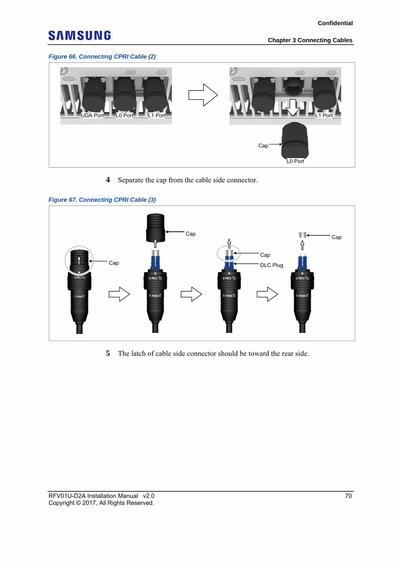
Figure 66. Connecting CPRI Cable (2)
4 Separate the cap from the cable side connector.
Figure 67. Connecting CPRI Cable (3)
5 The latch of cable side connector should be toward the rear side.
Cap
L0 Port
L0 Port L1 PortL1 Port UDA Port
Cap
Cap
DLC Plug
Cap
Cap
Confidential
Chapter 3 Connecting Cables
RFV01U-D2A Installation Manual v2.0 71 Copyright © 2017, All Rights Reserved.
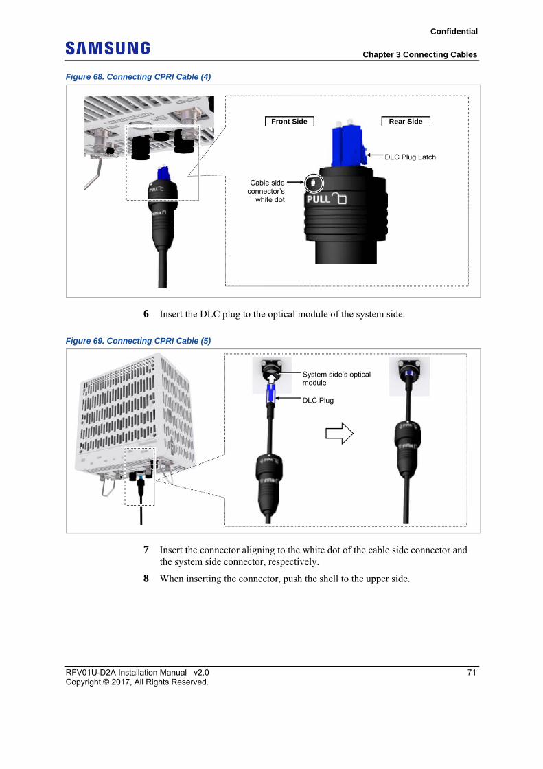
Figure 68. Connecting CPRI Cable (4)
6 Insert the DLC plug to the optical module of the system side.
Figure 69. Connecting CPRI Cable (5)
7 Insert the connector aligning to the white dot of the cable side connector and the system side connector, respectively.
8 When inserting the connector, push the shell to the upper side.
DLC Plug Latch
Cable sideconnector’s
white dot
Front Side Rear Side
DLC Plug
System side’s optical module
Confidential
Chapter 3 Connecting Cables
RFV01U-D2A Installation Manual v2.0 72 Copyright © 2017, All Rights Reserved.
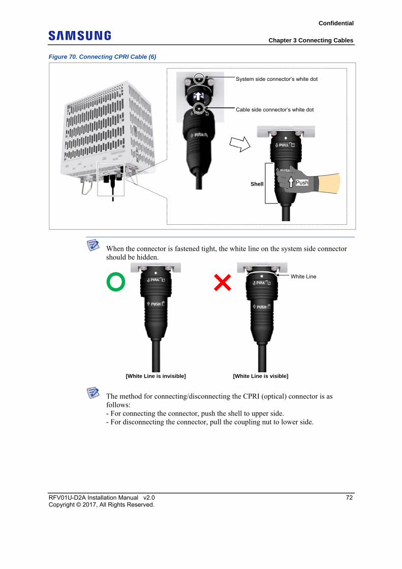
Figure 70. Connecting CPRI Cable (6)
When the connector is fastened tight, the white line on the system side connector should be hidden.
The method for connecting/disconnecting the CPRI (optical) connector is as follows: - For connecting the connector, push the shell to upper side. - For disconnecting the connector, pull the coupling nut to lower side.
Shell Push
System side connector’s white dot
Cable side connector’s white dot
White Line
[White Line is invisible] [White Line is visible]
Confidential
Chapter 3 Connecting Cables
RFV01U-D2A Installation Manual v2.0 73 Copyright © 2017, All Rights Reserved.
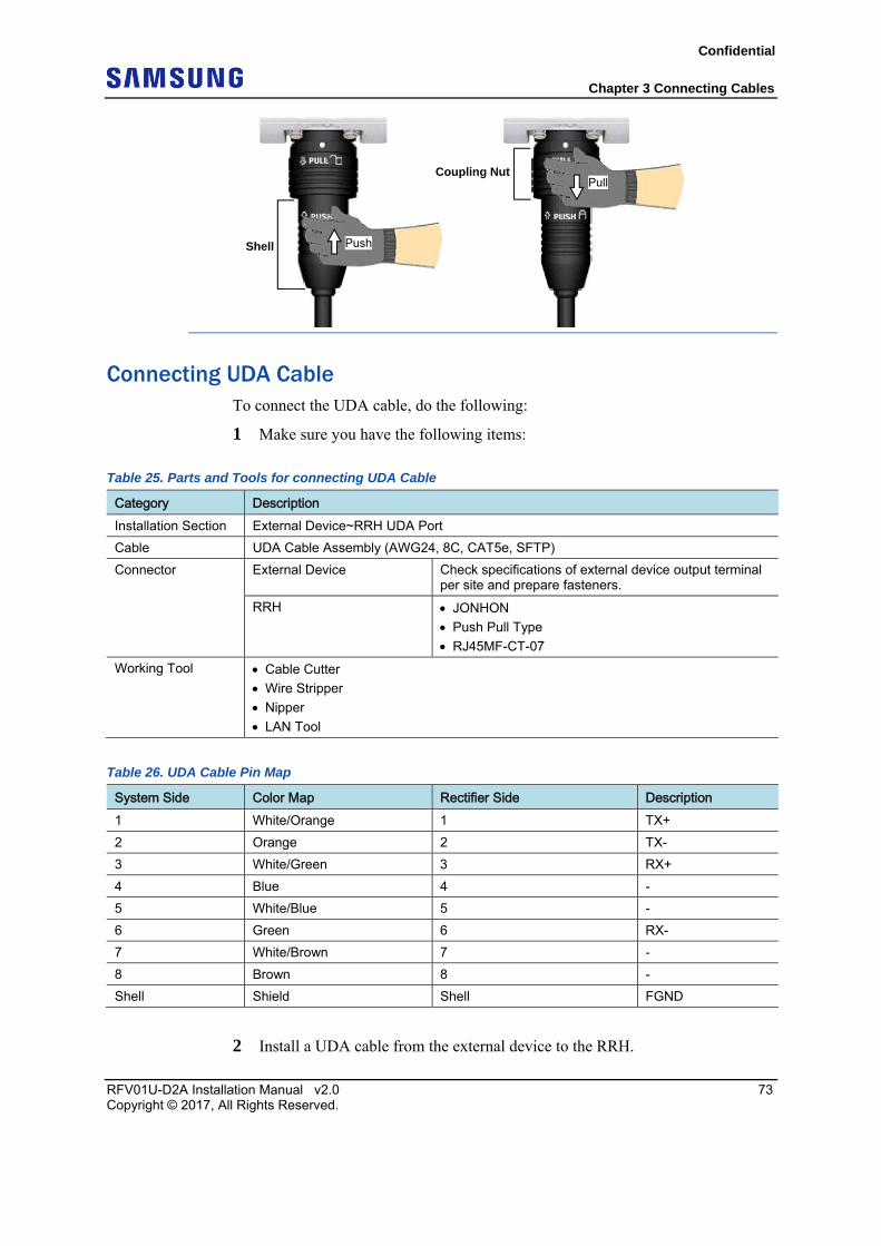
Connecting UDA Cable To connect the UDA cable, do the following:
1 Make sure you have the following items:
Table 25. Parts and Tools for connecting UDA Cable
Category Description Installation Section External Device~RRH UDA Port
Cable UDA Cable Assembly (AWG24, 8C, CAT5e, SFTP)
Connector External Device Check specifications of external device output terminal per site and prepare fasteners.
RRH JONHON
Push Pull Type
RJ45MF-CT-07
Working Tool Cable Cutter
Wire Stripper
Nipper
LAN Tool
Table 26. UDA Cable Pin Map
System Side Color Map Rectifier Side Description 1 White/Orange 1 TX+
2 Orange 2 TX-
3 White/Green 3 RX+
4 Blue 4 -
5 White/Blue 5 -
6 Green 6 RX-
7 White/Brown 7 -
8 Brown 8 -
Shell Shield Shell FGND
2 Install a UDA cable from the external device to the RRH.
Shell
Coupling Nut
Push
Pull
Confidential
Chapter 3 Connecting Cables
RFV01U-D2A Installation Manual v2.0 74 Copyright © 2017, All Rights Reserved.
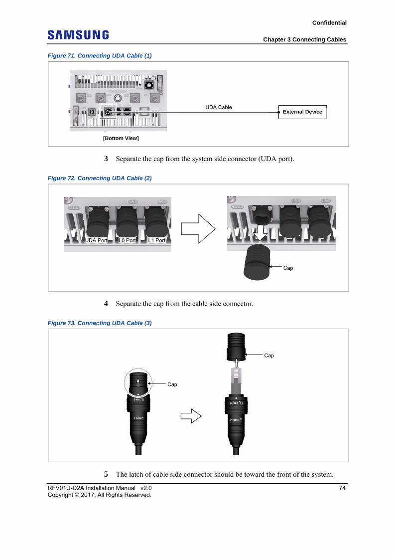
Figure 71. Connecting UDA Cable (1)
3 Separate the cap from the system side connector (UDA port).
Figure 72. Connecting UDA Cable (2)
4 Separate the cap from the cable side connector.
Figure 73. Connecting UDA Cable (3)
5 The latch of cable side connector should be toward the front of the system.
[Bottom View]
UDA Cable External Device
Cap
L0 Port L1 PortUDA Port
Cap
Cap
Confidential
Chapter 3 Connecting Cables
RFV01U-D2A Installation Manual v2.0 75 Copyright © 2017, All Rights Reserved.
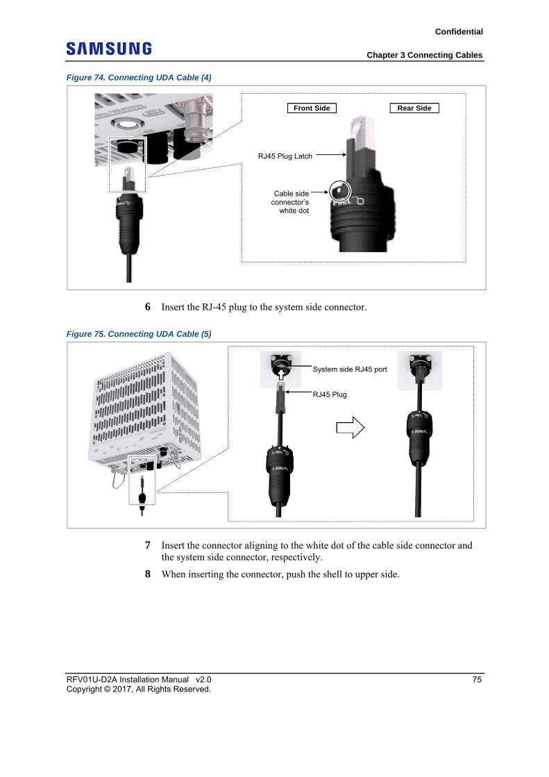
Figure 74. Connecting UDA Cable (4)
6 Insert the RJ-45 plug to the system side connector.
Figure 75. Connecting UDA Cable (5)
7 Insert the connector aligning to the white dot of the cable side connector and the system side connector, respectively.
8 When inserting the connector, push the shell to upper side.
RJ45 Plug Latch
Cable side connector’s
white dot
Front Side Rear Side
RJ45 Plug
System side RJ45 port
Confidential
Chapter 3 Connecting Cables
RFV01U-D2A Installation Manual v2.0 76 Copyright © 2017, All Rights Reserved.
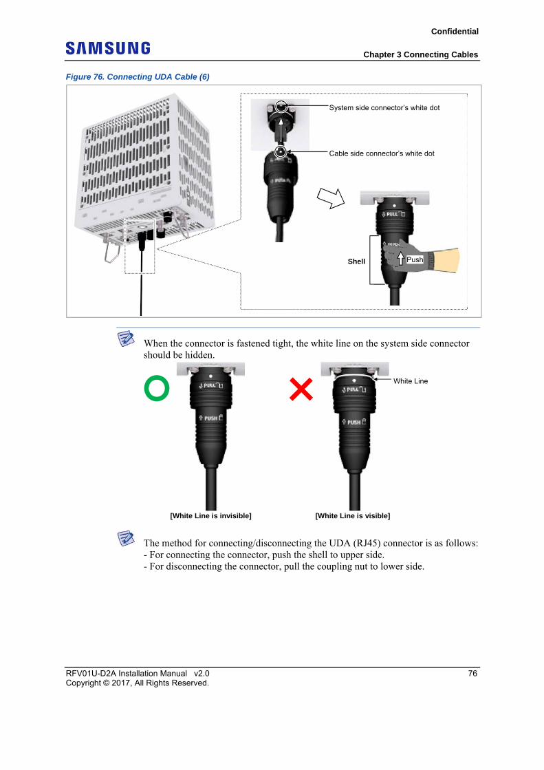
Figure 76. Connecting UDA Cable (6)
When the connector is fastened tight, the white line on the system side connector should be hidden.
The method for connecting/disconnecting the UDA (RJ45) connector is as follows: - For connecting the connector, push the shell to upper side. - For disconnecting the connector, pull the coupling nut to lower side.
System side connector’s white dot
Cable side connector’s white dot
Shell Push
White Line
[White Line is invisible] [White Line is visible]
Confidential
Chapter 3 Connecting Cables
RFV01U-D2A Installation Manual v2.0 77 Copyright © 2017, All Rights Reserved.
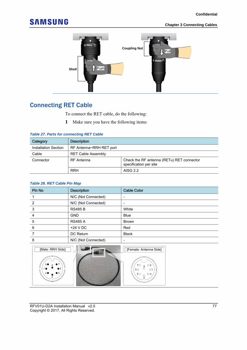
Connecting RET Cable To connect the RET cable, do the following:
1 Make sure you have the following items:
Table 27. Parts for connecting RET Cable
Category Description Installation Section RF Antenna~RRH RET port
Cable RET Cable Assembly
Connector RF Antenna Check the RF antenna (RETu) RET connector specification per site
RRH AISG 2.2
Table 28. RET Cable Pin Map
Pin No Description Cable Color 1 N/C (Not Connected) -
2 N/C (Not Connected) -
3 RS485 B White
4 GND Blue
5 RS485 A Brown
6 +24 V DC Red
7 DC Return Black
8 N/C (Not Connected) -
[Male: RRH Side] [Female: Antenna Side]
Shell
Coupling Nut
Push
Pull
Confidential
Chapter 3 Connecting Cables
RFV01U-D2A Installation Manual v2.0 78 Copyright © 2017, All Rights Reserved.
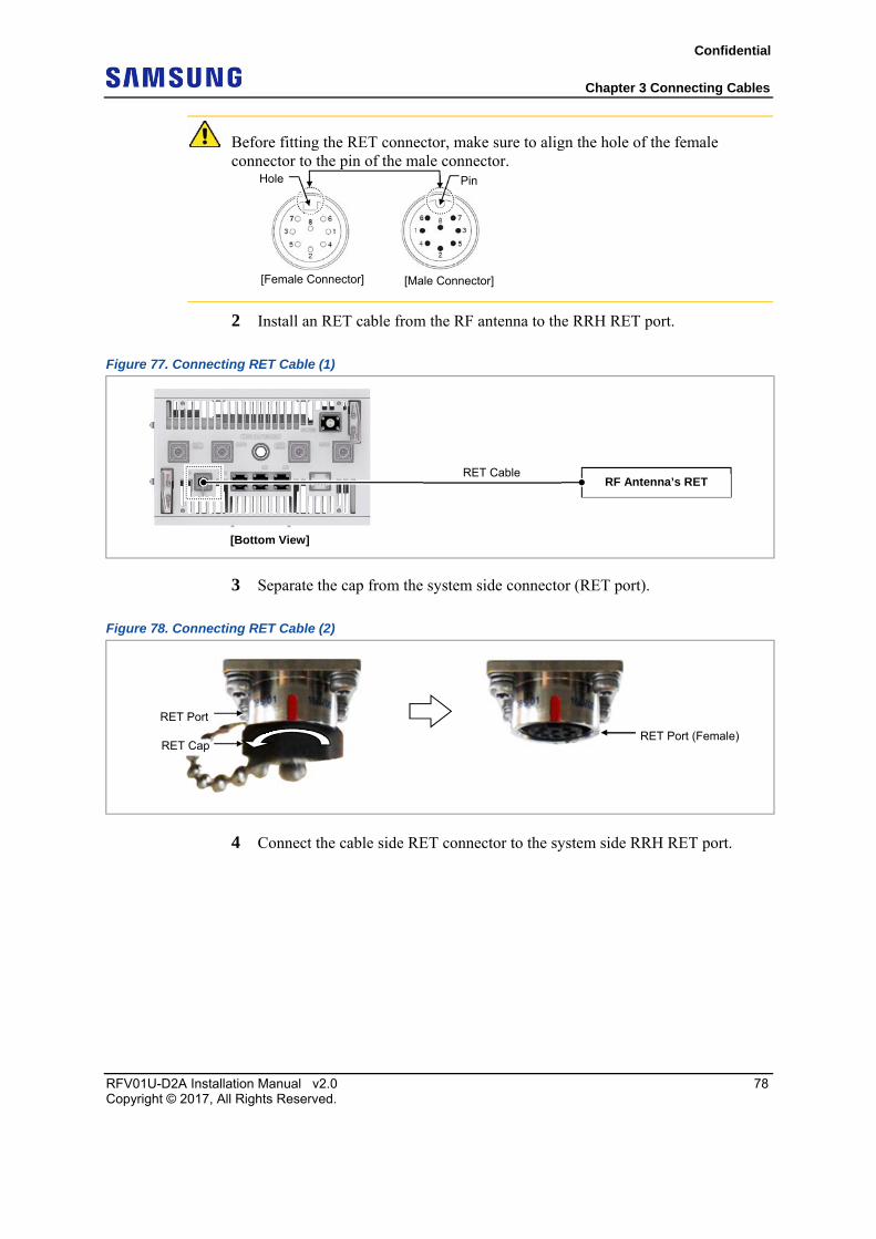
Before fitting the RET connector, make sure to align the hole of the female connector to the pin of the male connector.
2 Install an RET cable from the RF antenna to the RRH RET port.
Figure 77. Connecting RET Cable (1)
3 Separate the cap from the system side connector (RET port).
Figure 78. Connecting RET Cable (2)
4 Connect the cable side RET connector to the system side RRH RET port.
[Male Connector] [Female Connector]
Hole Pin
RF Antenna’s RET
[Bottom View]
RET Cable
RET Cap
RET Port
RET Port (Female)
Confidential
Chapter 3 Connecting Cables
RFV01U-D2A Installation Manual v2.0 79 Copyright © 2017, All Rights Reserved.
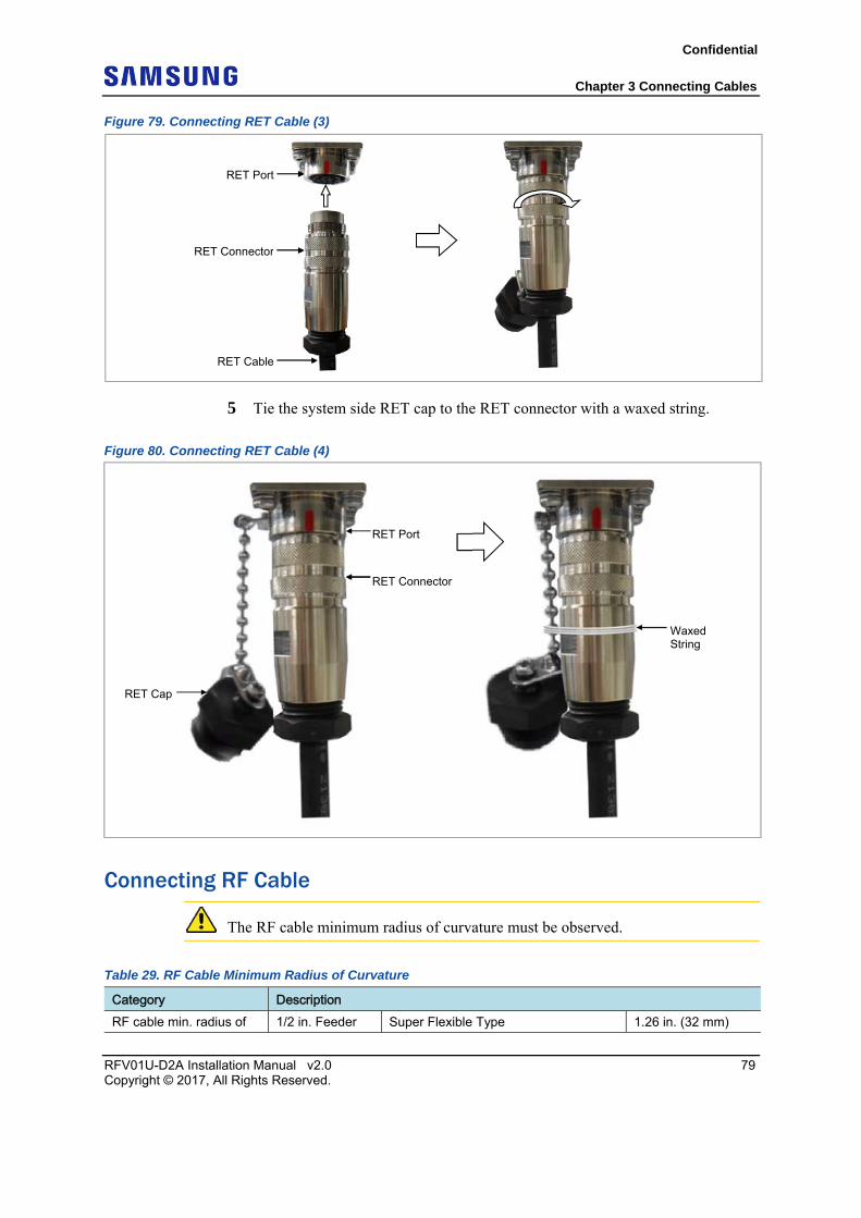
Figure 79. Connecting RET Cable (3)
5 Tie the system side RET cap to the RET connector with a waxed string.
Figure 80. Connecting RET Cable (4)
Connecting RF Cable
The RF cable minimum radius of curvature must be observed.
Table 29. RF Cable Minimum Radius of Curvature
Category Description RF cable min. radius of 1/2 in. Feeder Super Flexible Type 1.26 in. (32 mm)
RET Connector
RET Port
RET Cable
RET Cap
Waxed String
RET Connector
RET Port
Confidential
Chapter 3 Connecting Cables
RFV01U-D2A Installation Manual v2.0 80 Copyright © 2017, All Rights Reserved.
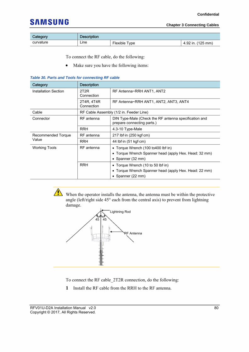
Category Description curvature Line Flexible Type 4.92 in. (125 mm)
To connect the RF cable, do the following:
Make sure you have the following items:
Table 30. Parts and Tools for connecting RF cable
Category Description Installation Section 2T2R
Connection RF Antenna~RRH ANT1, ANT2
2T4R, 4T4R Connection
RF Antenna~RRH ANT1, ANT2, ANT3, ANT4
Cable RF Cable Assembly (1/2 in. Feeder Line)
Connector RF antenna DIN Type-Male (Check the RF antenna specification and prepare connecting parts.)
RRH 4.3-10 Type-Male
Recommended Torque Value
RF antenna 217 lbfin (250 kgfcm)
RRH 44 lbfin (51 kgfcm)
Working Tools RF antenna Torque Wrench (100 to400 lbf·in)
Torque Wrench Spanner head (apply Hex. Head: 32 mm)
Spanner (32 mm)
RRH Torque Wrench (10 to 50 lbf·in)
Torque Wrench Spanner head (apply Hex. Head: 22 mm)
Spanner (22 mm)
When the operator installs the antenna, the antenna must be within the protective angle (left/right side 45° each from the central axis) to prevent from lightning damage.
To connect the RF cable_2T2R connection, do the following:
1 Install the RF cable from the RRH to the RF antenna.
Lightning Rod
45 45
RF Antenna
Confidential
Chapter 3 Connecting Cables
RFV01U-D2A Installation Manual v2.0 81 Copyright © 2017, All Rights Reserved.
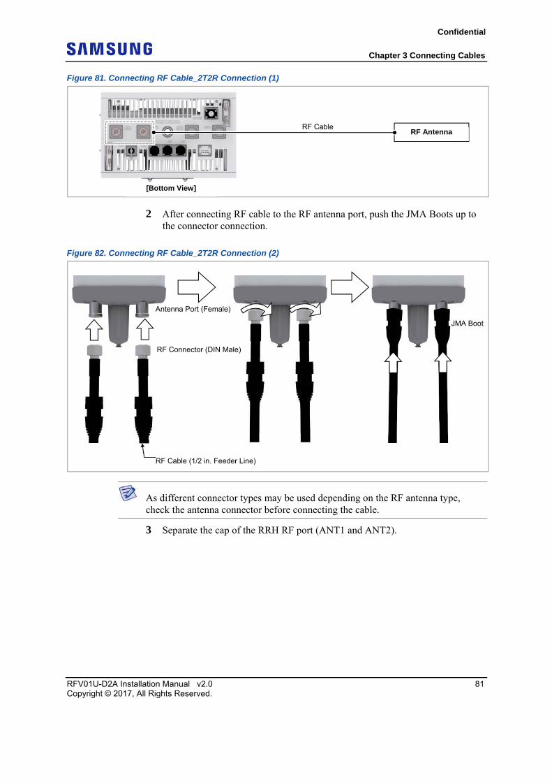
Figure 81. Connecting RF Cable_2T2R Connection (1)
2 After connecting RF cable to the RF antenna port, push the JMA Boots up to the connector connection.
Figure 82. Connecting RF Cable_2T2R Connection (2)
As different connector types may be used depending on the RF antenna type, check the antenna connector before connecting the cable.
3 Separate the cap of the RRH RF port (ANT1 and ANT2).
[Bottom View]
RF Antenna RF Cable
RF Cable (1/2 in. Feeder Line)
JMA Boot
Antenna Port (Female)
RF Connector (DIN Male)
Confidential
Chapter 3 Connecting Cables
RFV01U-D2A Installation Manual v2.0 82 Copyright © 2017, All Rights Reserved.
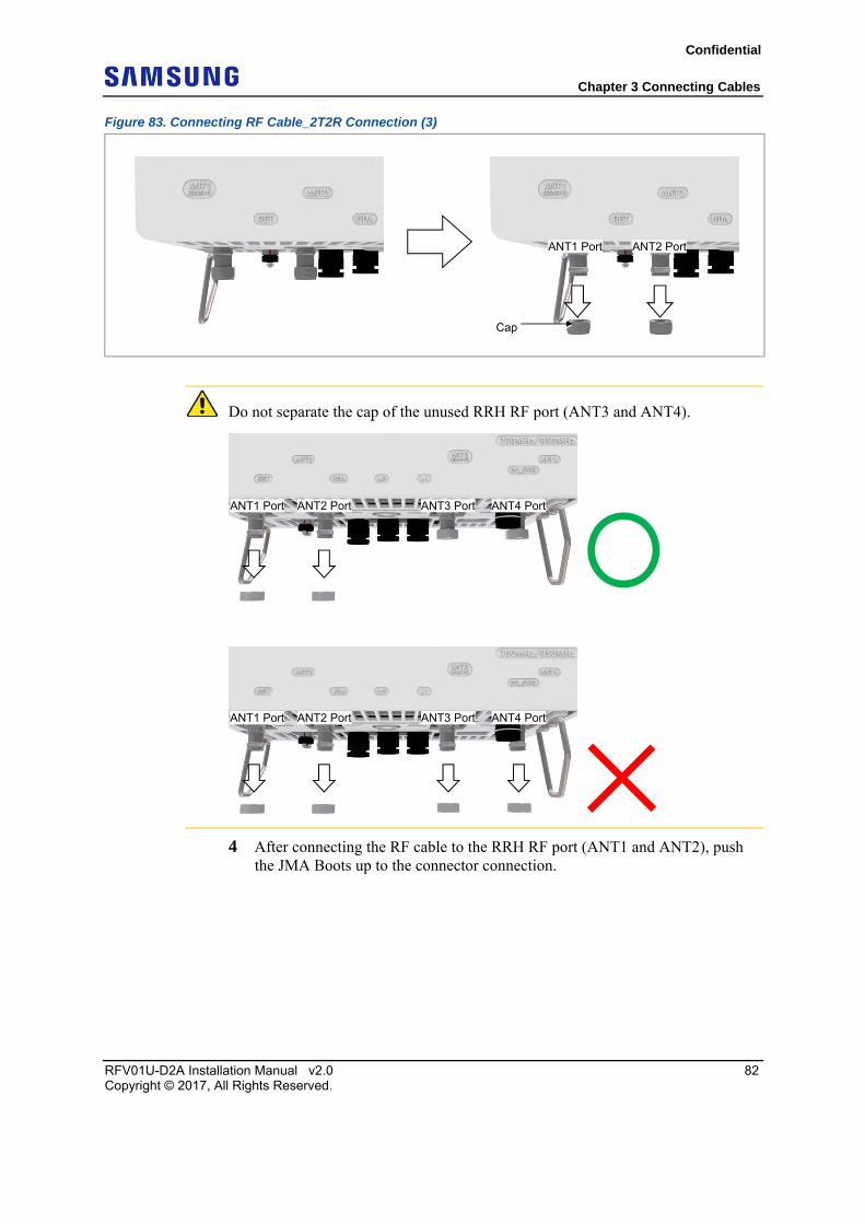
Figure 83. Connecting RF Cable_2T2R Connection (3)
Do not separate the cap of the unused RRH RF port (ANT3 and ANT4).
4 After connecting the RF cable to the RRH RF port (ANT1 and ANT2), push the JMA Boots up to the connector connection.
Cap
ANT1 Port ANT2 Port
ANT1 Port ANT2 Port ANT3 Port ANT4 Port
ANT1 Port ANT2 Port ANT3 Port ANT4 Port
Confidential
Chapter 3 Connecting Cables
RFV01U-D2A Installation Manual v2.0 83 Copyright © 2017, All Rights Reserved.
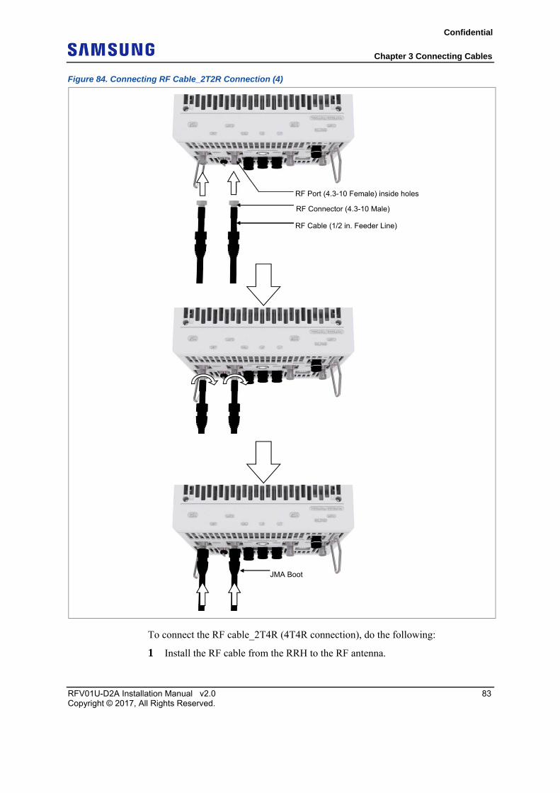
Figure 84. Connecting RF Cable_2T2R Connection (4)
To connect the RF cable_2T4R (4T4R connection), do the following:
1 Install the RF cable from the RRH to the RF antenna.
RF Port (4.3-10 Female) inside holes
RF Connector (4.3-10 Male)
RF Cable (1/2 in. Feeder Line)
JMA Boot
Confidential
Chapter 3 Connecting Cables
RFV01U-D2A Installation Manual v2.0 84 Copyright © 2017, All Rights Reserved.
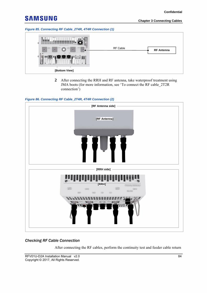
Figure 85. Connecting RF Cable_2T4R, 4T4R Connection (1)
2 After connecting the RRH and RF antenna, take waterproof treatment using JMA boots (for more information, see ‘To connect the RF cable_2T2R connection’)
Figure 86. Connecting RF Cable_2T4R, 4T4R Connection (2)
Checking RF Cable Connection
After connecting the RF cables, perform the continuity test and feeder cable return
[Bottom View]
RF Antenna RF Cable
[RF Antenna side]
[RF Antenna]
[RRH side]
[RRH]
Confidential
Chapter 3 Connecting Cables
RFV01U-D2A Installation Manual v2.0 85 Copyright © 2017, All Rights Reserved.
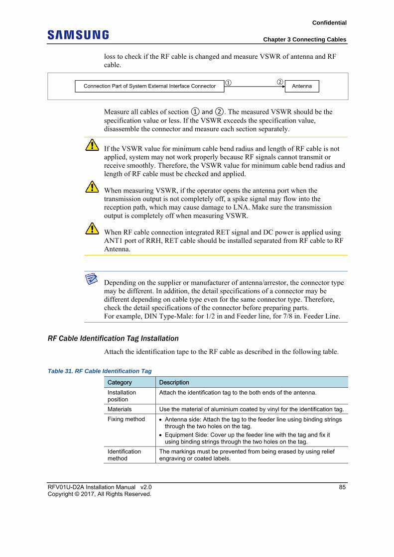
loss to check if the RF cable is changed and measure VSWR of antenna and RF cable.
Measure all cables of section ① and ②. The measured VSWR should be the specification value or less. If the VSWR exceeds the specification value, disassemble the connector and measure each section separately.
If the VSWR value for minimum cable bend radius and length of RF cable is not applied, system may not work properly because RF signals cannot transmit or receive smoothly. Therefore, the VSWR value for minimum cable bend radius and length of RF cable must be checked and applied.
When measuring VSWR, if the operator opens the antenna port when the transmission output is not completely off, a spike signal may flow into the reception path, which may cause damage to LNA. Make sure the transmission output is completely off when measuring VSWR.
When RF cable connection integrated RET signal and DC power is applied using ANT1 port of RRH, RET cable should be installed separated from RF cable to RF Antenna.
Depending on the supplier or manufacturer of antenna/arrestor, the connector type may be different. In addition, the detail specifications of a connector may be different depending on cable type even for the same connector type. Therefore, check the detail specifications of the connector before preparing parts. For example, DIN Type-Male: for 1/2 in and Feeder line, for 7/8 in. Feeder Line.
RF Cable Identification Tag Installation
Attach the identification tape to the RF cable as described in the following table.
Table 31. RF Cable Identification Tag
Category Description Installation position
Attach the identification tag to the both ends of the antenna.
Materials Use the material of aluminium coated by vinyl for the identification tag.
Fixing method Antenna side: Attach the tag to the feeder line using binding strings through the two holes on the tag.
Equipment Side: Cover up the feeder line with the tag and fix it using binding strings through the two holes on the tag.
Identification method
The markings must be prevented from being erased by using relief engraving or coated labels.
Connection Part of System External Interface Connector Antenna ① ②
Confidential
RFV01U-D2A Installation Manual v2.0 86 Copyright © 2017, All Rights Reserved.
Chapter 4 Inspect the Installation
This chapter describes the procedures to check the installation status.
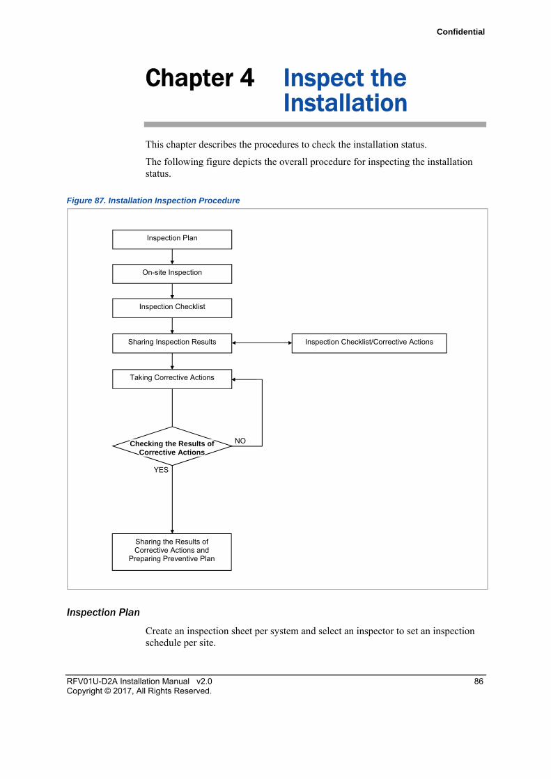
The following figure depicts the overall procedure for inspecting the installation status.
Figure 87. Installation Inspection Procedure
Inspection Plan
Create an inspection sheet per system and select an inspector to set an inspection schedule per site.
NO
YES
Sharing Inspection Results
Taking Corrective Actions
On-site Inspection
Inspection Checklist
Inspection Checklist/Corrective Actions
Sharing the Results of Corrective Actions and
Preparing Preventive Plan
Inspection Plan
Checking the Results of Corrective Actions
Confidential
Chapter 4 Inspect the Installation
RFV01U-D2A Installation Manual v2.0 87 Copyright © 2017, All Rights Reserved.
On-site Inspection and Inspection Checklist
The on-site inspection is to perform inspection visually or using instruments for each specification, standard, and installation status based on the inspection checklist at the site where the system is installed.
The inspector must record the results onto the inspection checklist during or after field inspection.
Sharing Inspection Results and Taking Corrective Actions
The inspector must share the inspection results (inspection checklist/corrective actions) with an installation operator and, the installation operator must take the corrective actions if necessary after reviewing the requirements.
Checking the Results of Corrective Actions
The inspector must check if the corrective actions are properly taken. If they are not sufficient, the inspector must ask the installation operator to take the corrective actions again.
Sharing the Results of Corrective Actions and Preparing Preventive Plan
After the corrective actions are all completed, the inspector must share the results with the installation operator and relevant departments. The inspector must prepare a preventive plan to avoid the reoccurrence of the same or similar problems.
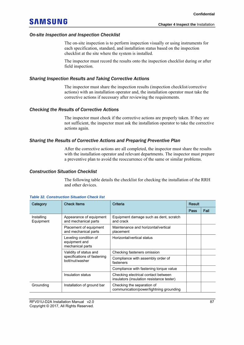
Construction Situation Checklist
The following table details the checklist for checking the installation of the RRH and other devices.
Table 32. Construction Situation Check list
Category Check Items Criteria Result
Pass Fail Installing Equipment
Appearance of equipment and mechanical parts
Equipment damage such as dent, scratch and crack
Placement of equipment and mechanical parts
Maintenance and horizontal/vertical placement
Leveling condition of equipment and mechanical parts
Horizontal/vertical status
Validity of status and specifications of fastening bolt/nut/washer
Checking fasteners omission
Compliance with assembly order of fasteners
Compliance with fastening torque value
Insulation status Checking electrical contact between insulators (insulation resistance tester)
Grounding Installation of ground bar Checking the separation of communication/power/lightning grounding
Confidential
Chapter 4 Inspect the Installation
RFV01U-D2A Installation Manual v2.0 88 Copyright © 2017, All Rights Reserved.
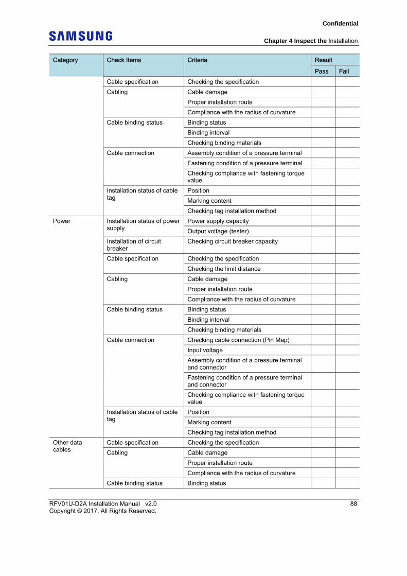
Category Check Items Criteria Result
Pass Fail Cable specification Checking the specification
Cabling Cable damage
Proper installation route
Compliance with the radius of curvature
Cable binding status Binding status
Binding interval
Checking binding materials
Cable connection Assembly condition of a pressure terminal
Fastening condition of a pressure terminal
Checking compliance with fastening torque value
Installation status of cable tag
Position
Marking content
Checking tag installation method
Power Installation status of power supply
Power supply capacity
Output voltage (tester)
Installation of circuit breaker
Checking circuit breaker capacity
Cable specification Checking the specification
Checking the limit distance
Cabling Cable damage
Proper installation route
Compliance with the radius of curvature
Cable binding status Binding status
Binding interval
Checking binding materials
Cable connection Checking cable connection (Pin Map)
Input voltage
Assembly condition of a pressure terminal and connector
Fastening condition of a pressure terminal and connector
Checking compliance with fastening torque value
Installation status of cable tag
Position
Marking content
Checking tag installation method
Other data cables
Cable specification Checking the specification
Cabling Cable damage
Proper installation route
Compliance with the radius of curvature
Cable binding status Binding status
Confidential
Chapter 4 Inspect the Installation
RFV01U-D2A Installation Manual v2.0 89 Copyright © 2017, All Rights Reserved.
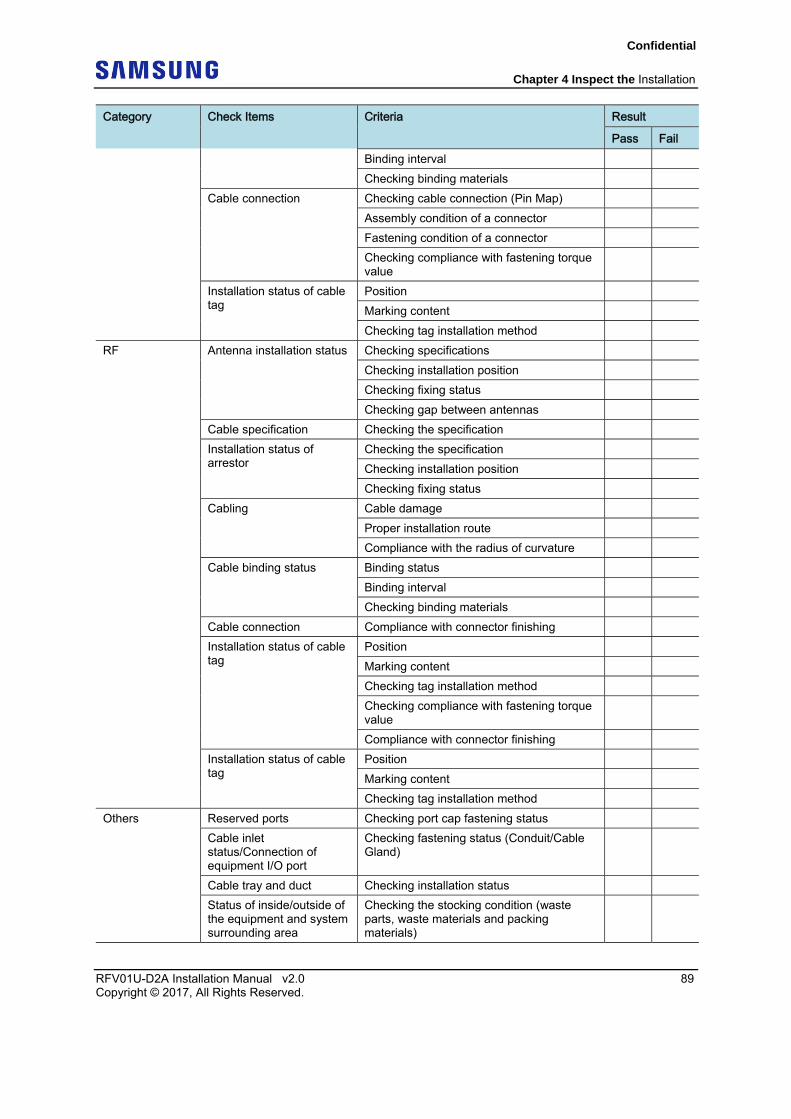
Category Check Items Criteria Result
Pass Fail Binding interval
Checking binding materials
Cable connection Checking cable connection (Pin Map)
Assembly condition of a connector
Fastening condition of a connector
Checking compliance with fastening torque value
Installation status of cable tag
Position
Marking content
Checking tag installation method
RF Antenna installation status Checking specifications
Checking installation position
Checking fixing status
Checking gap between antennas
Cable specification Checking the specification
Installation status of arrestor
Checking the specification
Checking installation position
Checking fixing status
Cabling Cable damage
Proper installation route
Compliance with the radius of curvature
Cable binding status Binding status
Binding interval
Checking binding materials
Cable connection Compliance with connector finishing
Installation status of cable tag
Position
Marking content
Checking tag installation method
Checking compliance with fastening torque value
Compliance with connector finishing
Installation status of cable tag
Position
Marking content
Checking tag installation method
Others Reserved ports Checking port cap fastening status
Cable inlet status/Connection of equipment I/O port
Checking fastening status (Conduit/Cable Gland)
Cable tray and duct Checking installation status
Status of inside/outside of the equipment and system surrounding area
Checking the stocking condition (waste parts, waste materials and packing materials)
Confidential
Chapter 4 Inspect the Installation
RFV01U-D2A Installation Manual v2.0 90 Copyright © 2017, All Rights Reserved.
Category Check Items Criteria Result
Pass Fail Opinion
■
Confidential
RFV01U-D2A Installation Manual v2.0 91 Copyright © 2017, All Rights Reserved.
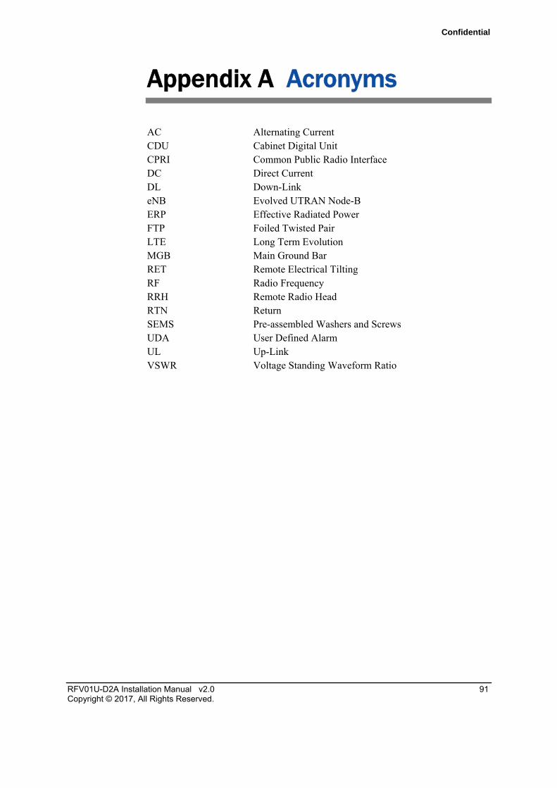
Appendix A Acronyms
AC Alternating Current CDU Cabinet Digital Unit CPRI Common Public Radio Interface DC Direct Current DL Down-Link eNB Evolved UTRAN Node-B ERP Effective Radiated Power FTP Foiled Twisted Pair LTE Long Term Evolution MGB Main Ground Bar RET Remote Electrical Tilting RF Radio Frequency RRH Remote Radio Head RTN Return SEMS Pre-assembled Washers and Screws UDA User Defined Alarm UL Up-Link VSWR Voltage Standing Waveform Ratio
Confidential
RFV01U-D2A Installation Manual v2.0 92 Copyright © 2017, All Rights Reserved.
Appendix B Sector Antenna Installation
This appendix describes the procedure to install the sector antenna and the precautions to be taken during the installation.
Cautions when Installing a Sector Antenna When installing a sector antenna, follow the precautions below:
Sector antennas should be installed vertically. (±1°)
Antenna is the precise material, so be careful not to make damage or form change.
When moving the antenna, use the tool suitable for rating. In addition, use the rated carrying device that is at least 200 % or more than the antenna considering the stability.
Be careful not to give too much pressure to the antenna.
If it rains, suspend the connection between the feeder cable and the antenna.
Fix it after adjusting the direction of antenna exactly.
Distance between the steel tower and the antenna and the distance between send-receive antennas are based on the antenna layout.
Attach the antenna on the position specified in the drawing.
Install the antenna not to make a feature change of the antenna considering the direction of the radiation
Connect the antenna not making the alien substance flowed so that Passive Inter-Modulation Distortion (PIMD) is not affected.
Measure VSWR of all antennas and the value should be within the regulated value.
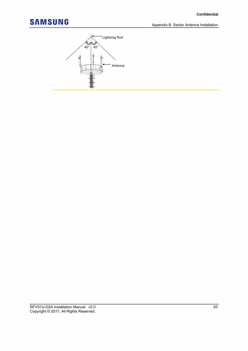
When you install the antenna, the antenna must be within the protective angle (left/right side 45° each from the central axis) to prevent the antenna from lightning damage.
Confidential
Appendix B Sector Antenna Installation
RFV01U-D2A Installation Manual v2.0 93 Copyright © 2017, All Rights Reserved.
Lightning Rod
45° 45°
Antenna
Confidential
Appendix B Sector Antenna Installation
RFV01U-D2A Installation Manual v2.0 94 Copyright © 2017, All Rights Reserved.
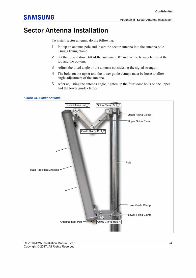
Sector Antenna Installation To install sector antenna, do the following:
1 Put up an antenna pole and insert the sector antenna into the antenna pole using a fixing clamp.
2 Set the up and down tilt of the antenna to 0° and fix the fixing clamps at the top and the bottom.
3 Adjust the tilted angle of the antenna considering the signal strength.
4 The bolts on the upper and the lower guide clamps must be loose to allow angle adjustment of the antenna.
5 After adjusting the antenna angle, tighten up the four loose bolts on the upper and the lower guide clamps.
Figure 88. Sector Antenna
Antenna Input Port
Pole
Main Radiation Direction
Upper Fixing Clamp
Lower Fixing Clamp
Upper Guide Clamp
Lower Guide Clamp
Guide Clamp Bolt_2
Guide Clamp Bolt_1Guide Clamp Bolt_3
Guide Clamp Bolt_4
Confidential
RFV01U-D2A Installation Manual v2.0 95 Copyright © 2017, All Rights Reserved.
Appendix C Clean the Optical Connectors
Introduction When connecting an optical cable to the system, the performance of the system can be decreased or failures can occur if the core section of an optical connector is dirty due to dust or foreign material. Therefore, the operator should clean the optical connector before connecting the optical cable to the system.
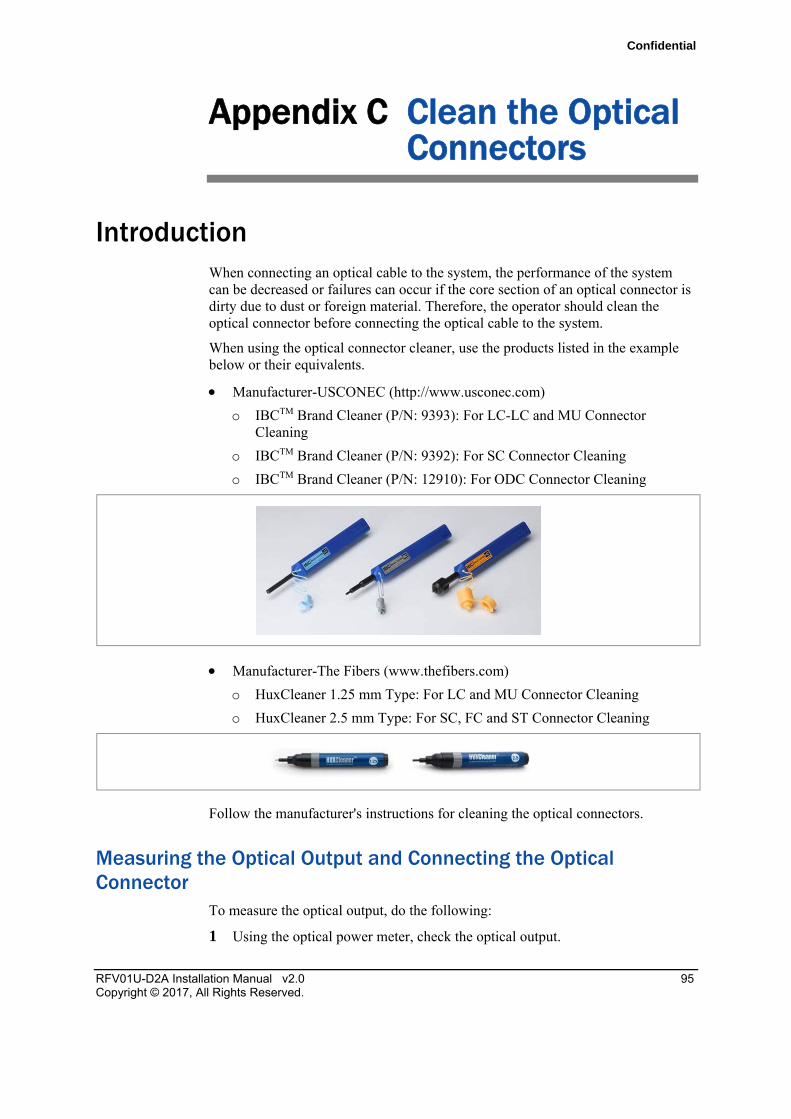
When using the optical connector cleaner, use the products listed in the example below or their equivalents.
Manufacturer-USCONEC (http://www.usconec.com)
o IBCTM Brand Cleaner (P/N: 9393): For LC-LC and MU Connector Cleaning
o IBCTM Brand Cleaner (P/N: 9392): For SC Connector Cleaning
o IBCTM Brand Cleaner (P/N: 12910): For ODC Connector Cleaning
Manufacturer-The Fibers (www.thefibers.com)
o HuxCleaner 1.25 mm Type: For LC and MU Connector Cleaning
o HuxCleaner 2.5 mm Type: For SC, FC and ST Connector Cleaning
Follow the manufacturer's instructions for cleaning the optical connectors.
Measuring the Optical Output and Connecting the Optical Connector
To measure the optical output, do the following:
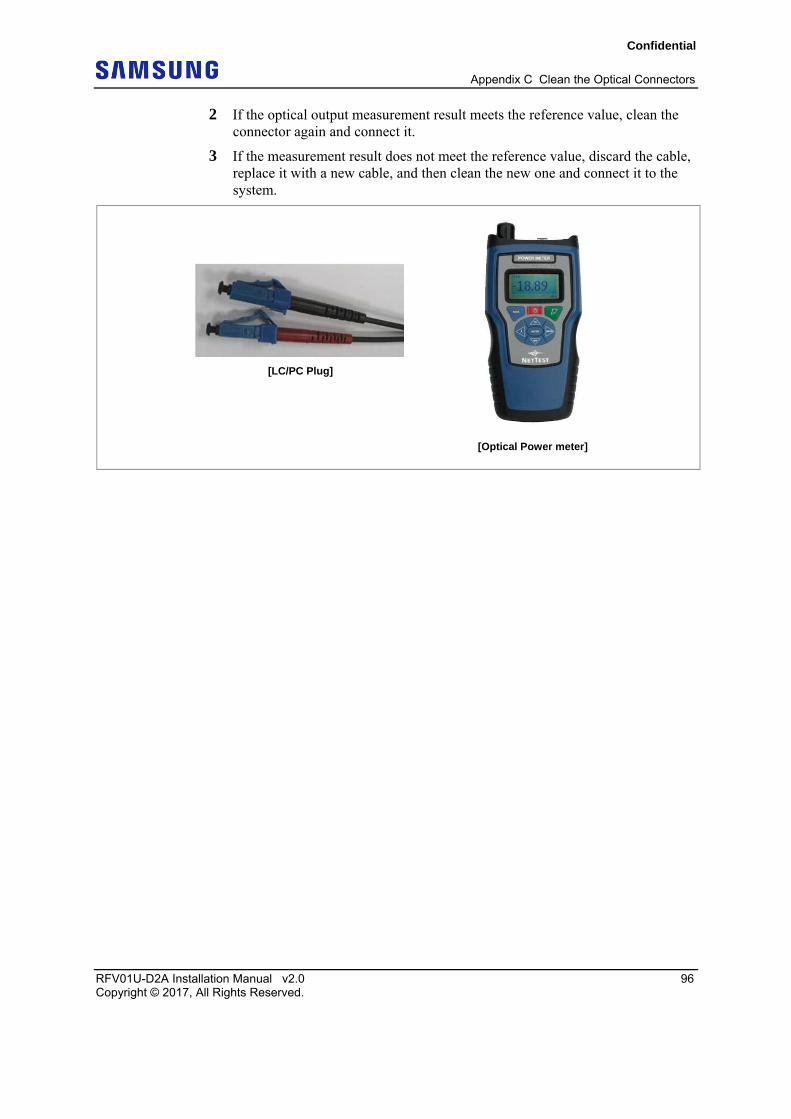
1 Using the optical power meter, check the optical output.
Confidential
Appendix C Clean the Optical Connectors
RFV01U-D2A Installation Manual v2.0 96 Copyright © 2017, All Rights Reserved.
2 If the optical output measurement result meets the reference value, clean the connector again and connect it.
3 If the measurement result does not meet the reference value, discard the cable, replace it with a new cable, and then clean the new one and connect it to the system.
[Optical Power meter]
[LC/PC Plug]
Confidential
RFV01U-D2A Installation Manual v2.0 97 Copyright © 2017, All Rights Reserved.
Appendix D Standard Torque
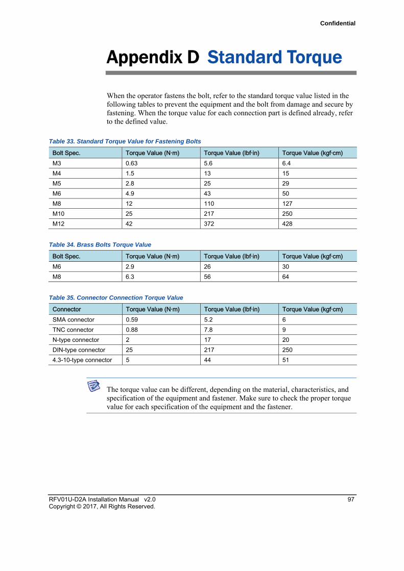
When the operator fastens the bolt, refer to the standard torque value listed in the following tables to prevent the equipment and the bolt from damage and secure by fastening. When the torque value for each connection part is defined already, refer to the defined value.
Table 33. Standard Torque Value for Fastening Bolts
Bolt Spec. Torque Value (N·m) Torque Value (lbf·in) Torque Value (kgf·cm) M3 0.63 5.6 6.4
M4 1.5 13 15
M5 2.8 25 29
M6 4.9 43 50
M8 12 110 127
M10 25 217 250
M12 42 372 428
Table 34. Brass Bolts Torque Value
Bolt Spec. Torque Value (N·m) Torque Value (lbf·in) Torque Value (kgf·cm) M6 2.9 26 30
M8 6.3 56 64
Table 35. Connector Connection Torque Value
Connector Torque Value (N·m) Torque Value (lbf·in) Torque Value (kgf·cm) SMA connector 0.59 5.2 6
TNC connector 0.88 7.8 9
N-type connector 2 17 20
DIN-type connector 25 217 250
4.3-10-type connector 5 44 51
The torque value can be different, depending on the material, characteristics, and specification of the equipment and fastener. Make sure to check the proper torque value for each specification of the equipment and the fastener.

�
RFV01U-D2AInstallation Manual Document Version 2.0 © 2017 Samsung Electronics Co., Ltd. All rights reserved.