Embed Size (px)
Citation preview
Chapter 3
HHOOWW TTEELLEEVVIISSIIOONN WWOORRKKSS
Long before computers became common to home and workplace, the telegraph,telephone, radio, television, and communication satellites, among other mediamarvels, put people instantly in touch with one another around the globe. Workingtogether, these devices make global communication possible; in combination, theyenable us to encode, transmit, store, retrieve, and display information in the formsof data, text, live-action images, and high-fidelity sounds, often in real time,thereby enriching communication. In contrast, the computer by itself is merely adata storage, retrieval, and processing device, utterly incapable of providing thecommunication functions we have come to expect from our media systems.
This chapter explains the development and function of traditional broad-casting systems that have enabled us to communicate instantly through radio andtelevision across continents for more than a century. The chapter also explains howthese systems are linked with computers through our telecommunications net-work, resulting in an infrastructure that makes streaming video, program sharing,and distribution possible through the Internet and e-mail channels. To understandwhat lies ahead in the video production field, one must understand how traditionalbroadcasting works and also how broadcasting is becoming integrated with com-puter and telecommunication systems to form our digital media network.
BROADCASTING AND THE SIGNIFICANCE OF CODE
The desire to communicate from afar is part of human nature. Long before radioand television enabled us to broadcast sounds and images instantly around theglobe, we invented less powerful means to send messages to distant places. Forexample, we invented the megaphone, which extends the reach of the humanvoice, but not greatly. Other methods of communicating long-distance haveincluded beacons, semaphore flags, drums, smoke signals, and telegraphy.
33
03-Shyles-45161.qxd 1/5/2007 7:30 PM Page 33
What these systems share is that they all rely on prior agreements (or codes)between senders and receivers about what various signals will mean. For example,anyone who does not know the sounds or letters associated with flag positions insemaphore will not get the message even if the flags can be clearly seen. It is thecode or pattern of intelligence conveyed by the flags, not the view of the flagsthemselves (the physical carrier), that makes it possible to convey messages. Inshort, clear reception of the carrier is a necessary but not a sufficient condition forsuccessful transmission of meaning. Successful communication relies on bothunimpeded reception of a message’s physical component and accurate decoding ofthe pattern of information (or intelligence) it contains. Of course, it is still possi-ble to misinterpret messages after they are received, but cultural issues of mean-ing are not even considered until an encoded message is received and decoded.
How is intelligence carried in a message system? A common feature of com-munication is the need to vary some aspect of a signal to encode information. Apattern of some kind must be crafted into some physical form for a message to begenerated, stored, transmitted, received, and consumed. And all patterns requiresome form of variation or change.
On a simpler level, consider again communication using semaphore flags.If the sender of semaphore flag signals fails to move the flags (no encoding), nomessage is sent even if the flags can be clearly seen. Similarly, in Morse code, ifthe telegrapher were to send nothing but dots at regular intervals, there would beno information to decode since there is nothing in Morse code associated with anendless series of dots.
In the technical jargon of radio and television broadcasting, the term forcreating a pattern of intelligence through variation is modulation. The term mod-ulation is synonymous for imposing a message (pattern, change, or variation) on acarrier.
Among the most pervasive, rapid, and successful systems ever developedfor communicating at a distance are radio and television broadcasting. To explainthe process of sending audio/visual messages via broadcasting, I first describe thephysical nature of radio energy, which makes broadcasting possible, and thendescribe how audio signals and televised scenes are encoded, transmitted, received,and decoded. After describing traditional broadcasting, I focus on significant devel-opments over the past half century that have extended its reach and range, includ-ing satellite broadcasting and cable television, both of which have advancedtraditional broadcasting without changing its analog nature. I then describe how themore recent transition from analog to digital platforms, integrating broadcastingwith computers and telecommunication networks, has brought a cornucopia of newvideo products, services, and opportunities to both producers and consumers.
34 P A R T I : C O M M U N I C A T I N G W I T H V I D E O
03-Shyles-45161.qxd 1/5/2007 7:30 PM Page 34
THE PHYSICAL NATURE OF RADIO ENERGY
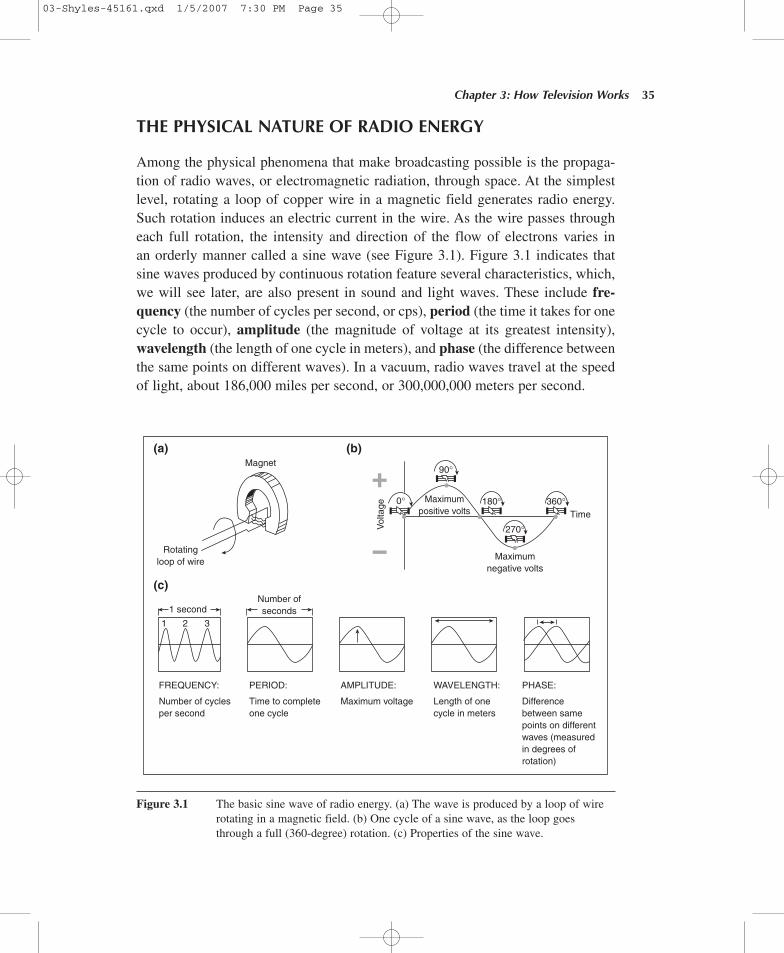
Among the physical phenomena that make broadcasting possible is the propaga-tion of radio waves, or electromagnetic radiation, through space. At the simplestlevel, rotating a loop of copper wire in a magnetic field generates radio energy.Such rotation induces an electric current in the wire. As the wire passes througheach full rotation, the intensity and direction of the flow of electrons varies inan orderly manner called a sine wave (see Figure 3.1). Figure 3.1 indicates thatsine waves produced by continuous rotation feature several characteristics, which,we will see later, are also present in sound and light waves. These include fre-quency (the number of cycles per second, or cps), period (the time it takes for onecycle to occur), amplitude (the magnitude of voltage at its greatest intensity),wavelength (the length of one cycle in meters), and phase (the difference betweenthe same points on different waves). In a vacuum, radio waves travel at the speedof light, about 186,000 miles per second, or 300,000,000 meters per second.
Chapter 3: How Television Works 35
Magnet
Rotatingloop of wire
FREQUENCY:
Number of cyclesper second
PERIOD:
Time to completeone cycle
AMPLITUDE:
Maximum voltage
WAVELENGTH:
Length of onecycle in meters
Maximumnegative volts
Time
Maximumpositive volts
90°
0° 180° 360°
270°
PHASE:
Differencebetween samepoints on differentwaves (measuredin degrees ofrotation)
Number ofseconds1 second
Vol
tage
1 2 3
(c)
(a) (b)
Figure 3.1 The basic sine wave of radio energy. (a) The wave is produced by a loop of wirerotating in a magnetic field. (b) One cycle of a sine wave, as the loop goesthrough a full (360-degree) rotation. (c) Properties of the sine wave.
03-Shyles-45161.qxd 1/5/2007 7:30 PM Page 35
PROPAGATING RADIO WAVES
In 1819, the Danish scientist Hans Oersted, while experimenting with electricaleffects of magnetic fields, discovered that magnetism and electricity were related.By 1831, Michael Faraday had discovered induction, the ability of an electric cur-rent in a wire to create a similar current in a nearby wire without physical contactbetween them. Based on Faraday’s discovery, Joseph Henry developed the firstefficient electromagnet.
In 1837, Samuel F. B. Morse used Henry’s discoveries about electromagnets topatent a long-distance telegraph system using electrical signals to encode messages.This method was a significant improvement over optical telegraphy systems in useat the time, which depended on telescopes and clear weather to send messages.Morse’s electrical telegraphy system was more powerful and reliable than the opti-cal systems then in use. It worked under more varied weather conditions and couldsend messages farther, more quickly, and more reliably than its predecessors.
As electrical telegraphy developed, it was observed that some “leakage” ofelectricity from telegraph wires appeared to magnetize some nearby metallicobjects. This phenomenon was explained in 1865 by the English physicist JamesClerk Maxwell, who presented evidence that electrical impulses emitted fromwires traveled through space in a manner similar in form and speed to light waves.Maxwell called them electromagnetic waves. Thomas Edison tried to capitalizeon this leakage phenomenon to send telegrams to people aboard moving trains.Unfortunately, the waves sent into the atmosphere by the telegraph wires were achaotic mixture of signals leaking from other wires in the area, making the pat-terned dots and dashes from any particular message unintelligible.
The problem of how to separate electromagnetic waves from one another wassolved by the German scientist Heinrich Hertz. In 1887, Hertz demonstrated thatan electromagnetic wave using an oscillating circuit could be propagated anddetected amid other waves. An oscillating circuit produces an electric current thatchanges direction at a stable frequency. An example of an oscillating circuit (albeita relatively slow one compared to radio frequencies) is that found in a typicalAmerican household electrical outlet, which supplies alternating current (AC) at60 cycles per second. In honor of Hertz’s discovery, the unit called a hertz (abbre-viated Hz) was adopted in the 1960s as a synonym for “cycles per second.”
It was soon confirmed that a radio wave, when propagated at a stable fre-quency, does not mix with waves of other frequencies. In 1895, the Italian scien-tist Guglielmo Marconi sent the first wireless telegraph message. These earlywireless messages were in the form of Morse code, using the simplest modulationtechnique—namely, an interrupted continuous wave (ICW). In this method ofradio modulation, a continuous, alternating current, made up of a succession of
36 P A R T I : C O M M U N I C A T I N G W I T H V I D E O
03-Shyles-45161.qxd 1/5/2007 7:30 PM Page 36
identical sine waves, is broken into a series of pulses corresponding to the dots anddashes of Morse code. This is done simply by opening and closing a circuit forrelatively short or long periods to turn the radio wave on or off. Thus, radio energywas used for the first time as the physical material to carry a pattern of intelligenceto encode information. Although ICW is still widely used, it is limited in thatit does not vary enough to carry sounds, such as music or speech. Eventually,advances in digital technology would make it possible to store enough pulses ofinformation in binary code (patterns of 0s and 1s) to render sounds and/or imageson CDs, videodisks, and computers. In Marconi’s day, however, further advanceswere needed to permit broadcasting of audio signals.
CONVERTING SOUND INTO ELECTRICAL ENERGY
Alexander Graham Bell made possible the advance from Morse code to the sendingof an electrical replica of the human voice (voice modulation). In 1876, Bell inventedthe telephone, which makes a current of electricity vary with changing sound wavesgenerated by the human voice. The telephone transmits a pattern of electricity thatfaithfully matches a pattern of sound waves made by speech. How does this happen?
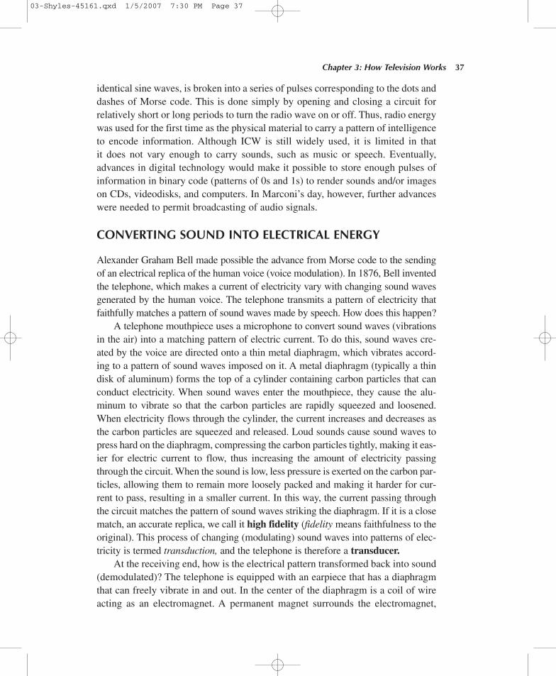
A telephone mouthpiece uses a microphone to convert sound waves (vibrationsin the air) into a matching pattern of electric current. To do this, sound waves cre-ated by the voice are directed onto a thin metal diaphragm, which vibrates accord-ing to a pattern of sound waves imposed on it. A metal diaphragm (typically a thindisk of aluminum) forms the top of a cylinder containing carbon particles that canconduct electricity. When sound waves enter the mouthpiece, they cause the alu-minum to vibrate so that the carbon particles are rapidly squeezed and loosened.When electricity flows through the cylinder, the current increases and decreases asthe carbon particles are squeezed and released. Loud sounds cause sound waves topress hard on the diaphragm, compressing the carbon particles tightly, making it eas-ier for electric current to flow, thus increasing the amount of electricity passingthrough the circuit. When the sound is low, less pressure is exerted on the carbon par-ticles, allowing them to remain more loosely packed and making it harder for cur-rent to pass, resulting in a smaller current. In this way, the current passing throughthe circuit matches the pattern of sound waves striking the diaphragm. If it is a closematch, an accurate replica, we call it high fidelity (fidelity means faithfulness to theoriginal). This process of changing (modulating) sound waves into patterns of elec-tricity is termed transduction, and the telephone is therefore a transducer.
At the receiving end, how is the electrical pattern transformed back into sound(demodulated)? The telephone is equipped with an earpiece that has a diaphragmthat can freely vibrate in and out. In the center of the diaphragm is a coil of wireacting as an electromagnet. A permanent magnet surrounds the electromagnet,
Chapter 3: How Television Works 37
03-Shyles-45161.qxd 1/5/2007 7:30 PM Page 37
supplying a force against which the electromagnet pulls. As the incoming currentvaries in strength, so does the magnetic force of the electromagnet. Magneticforces surrounding the diaphragm cause it to vibrate at the same rate, vibrating thesurrounding air. The sound waves generated by this motion create a replica of theoriginal sound. Figure 3.2 diagrams this process.
38 P A R T I : C O M M U N I C A T I N G W I T H V I D E O
Mouthpiece(transmitter)
Diaphragm Diaphragm
Cylinder ofcarbon particles
Electric current flowingthrough telephone lines
Permanentmagnet
Electromagnet
Earpiece(receiver)
Figure 3.2 Operation of the telephone, a simple transducer. Sound entering the mouthpiecevibrates a metal diaphragm atop a cylinder of carbon particles through which anelectric current is passing. This vibration produces a pattern of electric current thatreplicates a pattern of the sound waves. At the receiver end, the incoming currentcreates variations in the strength of the earpiece’s electromagnet. These variationscause the receiver diaphragm to vibrate, reproducing the original sound.
The encoding and decoding processes in microphones and loudspeakers workessentially the same way as in the telephone. Standard radio and television micro-phones, though, are sensitive to a fuller range of the audio spectrum and thereforehave higher fidelity than those found in telephones. Likewise, radio and televisionspeakers have more power and fidelity than telephone earpieces.
MODULATING RADIO WAVES WITH AUDIO SIGNALS
The telephone makes it possible to project an electrical version of the human voicethrough long distances over wires and then to recover a replica of the original soundfrom the transmitted electricity. It soon became possible to modulate radio wavesin a similar way without wires. This change resulted from the work of two electri-cal engineers, England’s Sir John Ambrose Fleming and America’s Lee De Forest.
03-Shyles-45161.qxd 1/5/2007 7:30 PM Page 38
Attenuation and Amplification
Sound waves, like radio waves, naturally dissipate as they move farther away fromtheir source. As distance increases, the strength of a wave decreases. This phe-nomenon is called attenuation. To picture this process, imagine the effect of drop-ping a stone into a pond of still water. The stone causes circular waves of water tomove away from the point where it hits, and as the waves move outward, theyweaken. At some distance, the original disturbance attenuates to such a degree thatthe water remains undisturbed by the original splash.
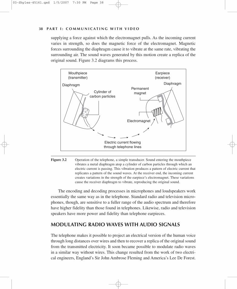
In Fleming’s day, it was already well known that electron motion produces currentin a closed circuit. In the language of electrical theory, Fleming knew that a voltageapplied to a metal wire conducts electrons. What Fleming discovered, however, wasthat an electrode inside an evacuated heated filament lamp (a glass vacuum tube) couldalso conduct an electric current. Fleming noticed a one-directional current between theheated filament (called the cathode) and the positive electrode (known as an anode orplate). Because it contained two elements, Fleming called the device a diode.
De Forest extended Fleming’s work by interposing a thin metal open-meshedgrid between the heated filament and the anode. When a separate voltage was fedto the grid, De Forest could control the magnitude of electricity flowing from thecathode to the plate. With a grid, De Forest obtained a large voltage change at theplate from just a small voltage change on the grid. Thus, by introducing a thirdelement to Fleming’s diode, De Forest’s triode made it possible to amplify weakradio signals received from distant radio transmitters. Figure 3.3 diagrams the tri-ode vacuum tube, the original heart of radio amplifiers. Since the 1950s, successive
Chapter 3: How Television Works 39
Plate
Glass envelope
Control grid
Vacuum
Cathode
Electron flow fromcathode to grid
Electron flow fromgrid to plate
Figure 3.3 A triode vacuum tube solved the problem of amplifying radio signals. Smallvoltage changes on the control grid modify the electrical flow from the cathode tothe plate.
03-Shyles-45161.qxd 1/5/2007 7:30 PM Page 39
generations of solid-state technologies (transistors, semiconductors, integratedcircuits, and microprocessors) have replaced vacuum tubes, but the principles ofamplification are the same in both tube and solid-state technologies.
Modulating the Carrier
By feeding an electrical signal converted from sound waves to the grid of a triode,relatively weak audio signals could be amplified enough to be used for radio trans-missions. However, before sound waves could be transmitted to distant pointswithout wires, the amplified audio signal had to be superimposed onto a radio fre-quency (RF) carrier. This is because sound waves are pressure waves and do notpropagate across space at the speed of light like electromagnetic radio waves.
The RF carrier is created with an oscillator, an electronic circuit that produces asine wave at a specific frequency. The RF carrier may then be modulated or made tovary by an audio signal (voice or other information) superimposed on it. In otherwords, the pattern imposed on the RF carrier is sound, converted into an electrical sig-nal, supplied by a microphone or some other audio source (e.g., a CD or cassette tape).
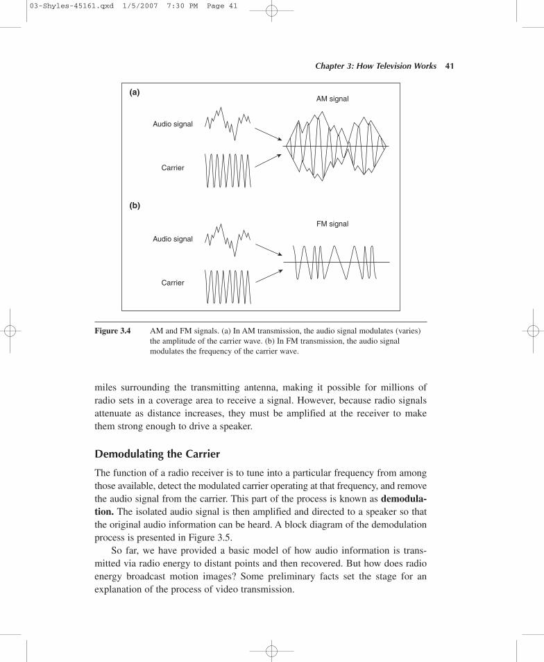
The two most common techniques of modulating a radio wave are amplitudeand frequency modulation. When an audio signal modulates the amplitude of acarrier, the process is called amplitude modulation (AM). When the audio signalmodulates the frequency of a carrier, the process is called frequency modulation(FM). In AM radio, the carrier consists of a sine wave whose amplitude is madeto copy the variations of an audio source. In FM radio, it is the frequency of thecarrier wave that is changed by an audio source. Figure 3.4 illustrates these twocommon types of voice modulation in radio broadcasting.
As it turns out, FM modulation is superior to AM because it produces betterfidelity with much higher noise immunity. For example, auto ignition noises andhigh-tension lines can cause hum and static on AM signals because those distur-bances can adversely affect the amplitude of the received carrier. By contrast, FMsignals are generally not affected by such impulse noises in the atmosphere.
Transmitting the Carrier
Audio signals imposed on RF carriers may be further amplified. Finally, they arefed from a transmitter to an antenna for propagation. In standard AM transmission,the range of frequencies used for radio carriers is between 535 and 1,705 kilohertz(abbreviated kHz, meaning thousands of hertz). Each channel is allocated a fre-quency range (or bandwidth) of 9 kHz to operate in. This means there is enoughspace in the radio spectrum allocated for 130 AM radio channels in any given area.
Roughly speaking, radio waves propagate in all directions unless they areintentionally altered from this pattern. The effective coverage area can radiate for
40 P A R T I : C O M M U N I C A T I N G W I T H V I D E O
03-Shyles-45161.qxd 1/5/2007 7:30 PM Page 40
miles surrounding the transmitting antenna, making it possible for millions ofradio sets in a coverage area to receive a signal. However, because radio signalsattenuate as distance increases, they must be amplified at the receiver to makethem strong enough to drive a speaker.
Demodulating the Carrier
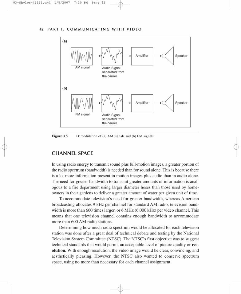
The function of a radio receiver is to tune into a particular frequency from amongthose available, detect the modulated carrier operating at that frequency, and removethe audio signal from the carrier. This part of the process is known as demodula-tion. The isolated audio signal is then amplified and directed to a speaker so thatthe original audio information can be heard. A block diagram of the demodulationprocess is presented in Figure 3.5.
So far, we have provided a basic model of how audio information is trans-mitted via radio energy to distant points and then recovered. But how does radioenergy broadcast motion images? Some preliminary facts set the stage for anexplanation of the process of video transmission.
Chapter 3: How Television Works 41
Audio signal
Carrier
Audio signal
Carrier
AM signal
FM signal
(a)
(b)
Figure 3.4 AM and FM signals. (a) In AM transmission, the audio signal modulates (varies)the amplitude of the carrier wave. (b) In FM transmission, the audio signalmodulates the frequency of the carrier wave.
03-Shyles-45161.qxd 1/5/2007 7:30 PM Page 41
CHANNEL SPACE
In using radio energy to transmit sound plus full-motion images, a greater portion ofthe radio spectrum (bandwidth) is needed than for sound alone. This is because thereis a lot more information present in motion images plus audio than in audio alone.The need for greater bandwidth to transmit greater amounts of information is anal-ogous to a fire department using larger diameter hoses than those used by home-owners in their gardens to deliver a greater amount of water per given unit of time.
To accommodate television’s need for greater bandwidth, whereas Americanbroadcasting allocates 9 kHz per channel for standard AM radio, television band-width is more than 660 times larger, or 6 MHz (6,000 kHz) per video channel. Thismeans that one television channel contains enough bandwidth to accommodatemore than 600 AM radio stations.
Determining how much radio spectrum would be allocated for each televisionstation was done after a great deal of technical debate and testing by the NationalTelevision System Committee (NTSC). The NTSC’s first objective was to suggesttechnical standards that would permit an acceptable level of picture quality or res-olution. With enough resolution, the video image would be clear, convincing, andaesthetically pleasing. However, the NTSC also wanted to conserve spectrumspace, using no more than necessary for each channel assignment.
42 P A R T I : C O M M U N I C A T I N G W I T H V I D E O
(a)
AM signal Audio Signalseparated fromthe carrier
Amplifier Speaker
(b)
FM signal Audio Signalseparated fromthe carrier
Amplifier Speaker
Figure 3.5 Demodulation of (a) AM signals and (b) FM signals.
03-Shyles-45161.qxd 1/5/2007 7:30 PM Page 42
The NTSC rightly viewed the radio spectrum as a limited natural resource,which it continues to be today, even though technological developments haveincreased its usable range. Despite these increases, the race for bandwidth bynew technologies (satellites, cell phones, digital applications, etc.) is unrelenting,making it essential to allocate its use wisely.
The job of the NTSC was tricky because any increase in image detail requiresa commensurate increase in bandwidth for each channel. Unfortunately, everyincrease in channel bandwidth reduces the total number of channels in a givenportion of the spectrum.
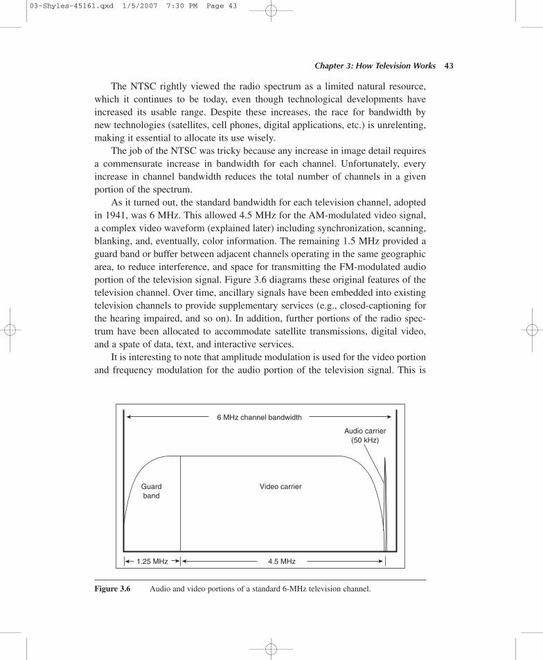
As it turned out, the standard bandwidth for each television channel, adoptedin 1941, was 6 MHz. This allowed 4.5 MHz for the AM-modulated video signal,a complex video waveform (explained later) including synchronization, scanning,blanking, and, eventually, color information. The remaining 1.5 MHz provided aguard band or buffer between adjacent channels operating in the same geographicarea, to reduce interference, and space for transmitting the FM-modulated audioportion of the television signal. Figure 3.6 diagrams these original features of thetelevision channel. Over time, ancillary signals have been embedded into existingtelevision channels to provide supplementary services (e.g., closed-captioning forthe hearing impaired, and so on). In addition, further portions of the radio spec-trum have been allocated to accommodate satellite transmissions, digital video,and a spate of data, text, and interactive services.
It is interesting to note that amplitude modulation is used for the video portionand frequency modulation for the audio portion of the television signal. This is
Chapter 3: How Television Works 43
Video carrier
6 MHz channel bandwidth
Audio carrier(50 kHz)
Guardband
1.25 MHz 4.5 MHz
Figure 3.6 Audio and video portions of a standard 6-MHz television channel.
03-Shyles-45161.qxd 1/5/2007 7:30 PM Page 43
because FM is less subject to noise and interference than AM, making it lesssubject to static and therefore more suitable for audio reception. Furthermore, AMis better suited for video transmission because it exhibits fewer problems caused bymultipath reception of the signal. Multipath reception occurs when the same signalreflects from obstacles such as buildings and bridges, reaching a receiving antennafrom more than one path. Because the distance traveled by multipath signals is usu-ally different, different parts of the signal arrive at the antenna at the same time. ForAM signals, this causes less severe interference at the television receiver than wouldoccur if the signals were FM.
CONVERTING LIGHT INTO ELECTRICAL ENERGY
Just as telephone and radio technologies harness natural qualities of electricity andelectromagnetic radiation to transmit voice-modulated audio signals, televisionrelies on natural phenomena of photoelectric effects, including photoconductivityand photoemissive effect, to convert light into, and back from, electrical energy.
Photoconductivity
To change light into electricity, video depends on photoconductivity, which occurswhen light on some metals increases the flow of electricity in those metals. One ofthe earliest examples of photoconductivity was observed in 1873 with the metalselenium. When selenium was used in an electrical circuit, the current through itincreased during exposure to light. Unfortunately for video applications, seleniumresponds too slowly to light to be useful for replicating natural motions. But luckily,cesium silver and other silver-based materials are excellent for such applications.
Photoemissive Effect
In the photoemissive effect, discovered by Hertz in 1887, visible light results fromsome materials’ exposure to energy that may not be visible to the eye. Sources ofsuch energy include streams of electrical energy or photons of higher-than-visiblelight energy, such as ultraviolet rays or X-rays. The photoemissive effect is similarto that seen in radium dials once used to make watch faces glow in the dark.
In the picture tube of a television receiver, the inside of the screen is coated withfluorescent material. When a stream of electrons strikes the screen, it glows becauseof the photoemissive effect. As the stream of electrons is made stronger, the portionof the screen struck by the electron stream glows more brightly. When the stream ismade weaker, the glow decreases. If the stream can be modulated in accordance withthe darker and brighter portions of a scene focused by the lens of a television camera,
44 P A R T I : C O M M U N I C A T I N G W I T H V I D E O
03-Shyles-45161.qxd 1/5/2007 7:30 PM Page 44
that scene can be rendered on the screen. If the re-creation process can be donequickly enough, then smooth motion can be rendered convincingly.
In monochrome (black-and-white) television receivers, the fluorescent mater-ial needs only to be able to glow with a range of brightness roughly proportionalto the intensity of the stream of electrons hitting it; color is of no consequence—only brightness variations are important. However, in color television, materialsthat glow with different colors when streams of electrons hit them must be used.To understand this process, let us begin with the major components of the mono-chrome television system.
MONOCHROME VIDEO
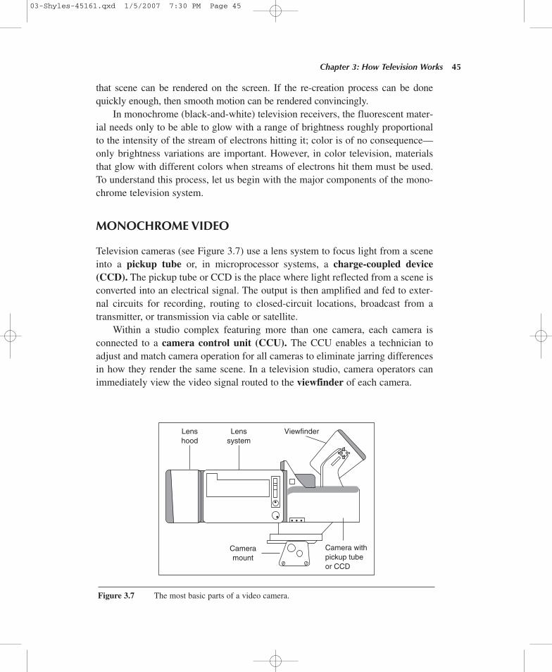
Television cameras (see Figure 3.7) use a lens system to focus light from a sceneinto a pickup tube or, in microprocessor systems, a charge-coupled device(CCD). The pickup tube or CCD is the place where light reflected from a scene isconverted into an electrical signal. The output is then amplified and fed to exter-nal circuits for recording, routing to closed-circuit locations, broadcast from atransmitter, or transmission via cable or satellite.
Within a studio complex featuring more than one camera, each camera isconnected to a camera control unit (CCU). The CCU enables a technician toadjust and match camera operation for all cameras to eliminate jarring differencesin how they render the same scene. In a television studio, camera operators canimmediately view the video signal routed to the viewfinder of each camera.
Chapter 3: How Television Works 45
Lenshood
Lenssystem
Viewfinder
Cameramount
Camera withpickup tubeor CCD
Figure 3.7 The most basic parts of a video camera.
03-Shyles-45161.qxd 1/5/2007 7:30 PM Page 45
SCANNING
Transmitting all the details of a given picture simultaneously over the same circuitwould lead to a chaotic mixing of signals in a single output, resulting in an unintelli-gible product similar to what jigsaw puzzles tend to look like when they are dumpedfrom their boxes. Such visual chaos is analogous to what Edison faced when he triedto send intermixed wireless telegraph signals to receivers aboard moving trains.
To maintain the fidelity of the original image seen by the camera when it isreceived by a television set, small areas of the picture are converted into discrete mag-nitudes of electric current matching the brightness information present in each por-tion, and then each is sent out in order. This is done so each picture element (pixel)can be received and converted into light without being confused with any others.
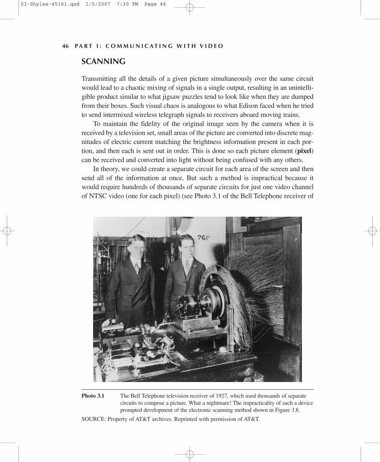
In theory, we could create a separate circuit for each area of the screen and thensend all of the information at once. But such a method is impractical because itwould require hundreds of thousands of separate circuits for just one video channelof NTSC video (one for each pixel) (see Photo 3.1 of the Bell Telephone receiver of
46 P A R T I : C O M M U N I C A T I N G W I T H V I D E O
Photo 3.1 The Bell Telephone television receiver of 1927, which used thousands of separatecircuits to compose a picture. What a nightmare! The impracticality of such a deviceprompted development of the electronic scanning method shown in Figure 3.8.
SOURCE: Property of AT&T archives. Reprinted with permission of AT&T.
03-Shyles-45161.qxd 1/5/2007 7:30 PM Page 46
1927). Instead, a scanning method is used to transmit the brightness information foreach pixel in turn. Scanning makes it possible to use just one circuit per channel.
The original monochrome video system converted picture information into elec-trical signals by focusing light onto a mosaic of pixels, each composed of an indi-vidual cesium silver globule. In such a system, when a scene to be televised wasfocused on the mosaic, electrons became stored in each pixel in magnitudes roughlyproportional to the intensity of light focused on each one. Stored electrons were theninstantly attracted by an anode in the camera tube, leaving the mosaic with a copyof the original scene in the form of varying amounts of electrical charge.
In American broadcasting, the traditional NTSC video mosaic is currentlycomposed of 525 horizontal lines, containing about 211,000 pixels. An electrongun is used to scan each line from left to right, top to bottom, in an orderly fash-ion. As the electron beam passes each pixel, it replaces electrons lost to the anode,enabling the video signal to exist in an external circuit. This signal is then coupledto video amplifiers for immediate transmission.
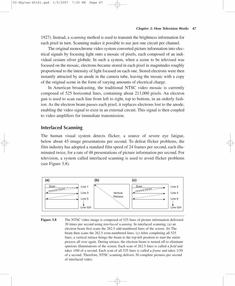
Interlaced Scanning
The human visual system detects flicker, a source of severe eye fatigue,below about 45 image presentations per second. To defeat flicker problems, thefilm industry has adopted a standard film speed of 24 frames per second, each illu-minated twice, for a rate of 48 presentations of picture information per second. Fortelevision, a system called interlaced scanning is used to avoid flicker problems(see Figure 3.8).
Chapter 3: How Television Works 47
(a) (b) (c)
Scan Line 1
Line 3
Line 5
Line 525
Line 2
Line 4
Line 6
Line 524
Horizontal RetraceScan
Horizontal Retrace
VerticalRetrace
Figure 3.8 The NTSC video image is composed of 525 lines of picture information delivered30 times per second using interlaced scanning. In interlaced scanning, (a) anelectron beam first scans the 262.5 odd-numbered lines of the screen. (b) Thebeam then scans the 262.5 even-numbered lines. (c) After completing all 525lines, a vertical retrace brings the beam to the top-left position to start the entireprocess all over again. During retrace, the electron beam is turned off to eliminatespurious illuminations of the screen. Each scan of 262.5 lines is called a field andtakes 1/60 of a second. Each scan of all 525 lines is called a frame and takes 1/30of a second. Therefore, NTSC scanning delivers 30 complete pictures per secondof interlaced video.
03-Shyles-45161.qxd 1/5/2007 7:30 PM Page 47
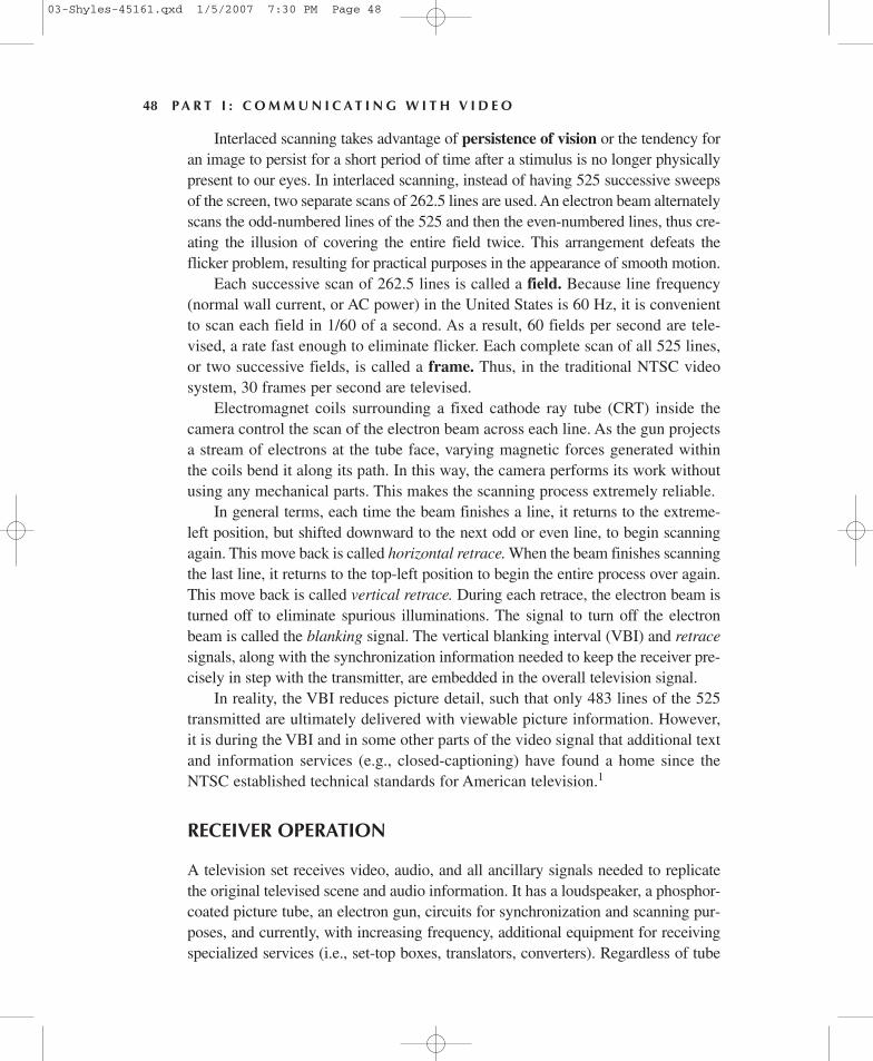
Interlaced scanning takes advantage of persistence of vision or the tendency foran image to persist for a short period of time after a stimulus is no longer physicallypresent to our eyes. In interlaced scanning, instead of having 525 successive sweepsof the screen, two separate scans of 262.5 lines are used. An electron beam alternatelyscans the odd-numbered lines of the 525 and then the even-numbered lines, thus cre-ating the illusion of covering the entire field twice. This arrangement defeats theflicker problem, resulting for practical purposes in the appearance of smooth motion.
Each successive scan of 262.5 lines is called a field. Because line frequency(normal wall current, or AC power) in the United States is 60 Hz, it is convenientto scan each field in 1/60 of a second. As a result, 60 fields per second are tele-vised, a rate fast enough to eliminate flicker. Each complete scan of all 525 lines,or two successive fields, is called a frame. Thus, in the traditional NTSC videosystem, 30 frames per second are televised.
Electromagnet coils surrounding a fixed cathode ray tube (CRT) inside thecamera control the scan of the electron beam across each line. As the gun projectsa stream of electrons at the tube face, varying magnetic forces generated withinthe coils bend it along its path. In this way, the camera performs its work withoutusing any mechanical parts. This makes the scanning process extremely reliable.
In general terms, each time the beam finishes a line, it returns to the extreme-left position, but shifted downward to the next odd or even line, to begin scanningagain. This move back is called horizontal retrace. When the beam finishes scanningthe last line, it returns to the top-left position to begin the entire process over again.This move back is called vertical retrace. During each retrace, the electron beam isturned off to eliminate spurious illuminations. The signal to turn off the electronbeam is called the blanking signal. The vertical blanking interval (VBI) and retracesignals, along with the synchronization information needed to keep the receiver pre-cisely in step with the transmitter, are embedded in the overall television signal.
In reality, the VBI reduces picture detail, such that only 483 lines of the 525transmitted are ultimately delivered with viewable picture information. However,it is during the VBI and in some other parts of the video signal that additional textand information services (e.g., closed-captioning) have found a home since theNTSC established technical standards for American television.1
RECEIVER OPERATION
A television set receives video, audio, and all ancillary signals needed to replicatethe original televised scene and audio information. It has a loudspeaker, a phosphor-coated picture tube, an electron gun, circuits for synchronization and scanning pur-poses, and currently, with increasing frequency, additional equipment for receivingspecialized services (i.e., set-top boxes, translators, converters). Regardless of tube
48 P A R T I : C O M M U N I C A T I N G W I T H V I D E O
03-Shyles-45161.qxd 1/5/2007 7:30 PM Page 48
size, the standard NTSC aspect ratio of tube height to width is three units by fourunits (4:3), respectively. As with the television camera, the neck of the picture tubeis fitted with magnetic deflection coils that control the direction of an electron beam.The beam scans horizontal paths across the picture tube’s phosphor coating.
When a television signal is received, the sound component (transmitted asFM) is routed to circuits where it is demodulated and sent to a loudspeaker. Thevideo or AM portion of the signal is routed to the picture tube, where it directsthe electron beam to emit electrons in amounts roughly in proportion to the bright-ness levels of the original scene. As the electron beam sweeps across the face ofthe picture tube, its varying intensities cause variations in the brightness of thephosphors, replicating the original scene. To synchronize the video signal so thatpixels can be reassembled without mixing them up, deflection coils around theneck of the picture tube are fed horizontal and vertical sync pulses from the orig-inal video signal. These pulses control the deflection of the electron beam acrossthe screen, thus keeping the receiver in step with the original signal.
COLOR TRANSMISSION AND RECEPTION
Color television broadcasting began after the monochrome system was alreadyin place and millions of black-and-white sets were in use. This made it desirable tofind a color system compatible with monochrome technology (hence economic andmarketing constraints were at work on even the most basic engineering decisionsfrom the beginning). To make color television compatible with monochrome trans-mission, color information was added to the monochrome signal without changingthe 6-MHz bandwidth set aside for each TV channel. In addition, both black-and-white and color receivers were made capable of receiving both monochrome andcolor signals (a requirement called backward compatibility). This meant transmis-sion had to be virtually identical for both monochrome and color systems.
Chrominance, Luminance, and Saturation
To transmit chrominance (color or hue) information, the color camera’s opticalsystem separates the light entering it into three primary colors: red, blue, andgreen. It is a fortunate characteristic of human vision that virtually any color canbe reproduced from these additive primary colors. Furthermore, any colored lightcan be specified with only two additional qualities: luminance (or brightness) andsaturation (or vividness). Saturation can be thought of as the degree to whicha color is free from impurities, such as dilution by white light. Low-saturationcolors are paler, whereas highly saturated colors are more pure and vivid.
In early color cameras, light was broken into its primary color componentswith filters and a set of dichroic mirrors. A dichroic mirror passes light at one
Chapter 3: How Television Works 49
03-Shyles-45161.qxd 1/5/2007 7:30 PM Page 49
wavelength while reflecting light at other wavelengths. Today, most color camerasuse a prism block called a beam splitter to break light into its primary colors.
Once the light has been split, the separate light beams are directed into threeseparate pickup tubes for processing into video signals. When a CCD micro-processor is used, a silicon lattice absorbs different wavelengths of light at differ-ent depths to distinguish colors. In either case, the patterns of electrical voltagegenerated in an external circuit match the levels of the original pattern of lightreceived by the camera.
Some cameras use a single imaging element with a filter to separate incominglight into its component values. Others use filters to separate light into only twocolors, as well as additional microprocessors to assign values to the third colorneeded to reproduce the colors the camera is seeing.
In color cameras, video signals from the three pickup tubes or the CCD arecombined to produce a signal containing all of the picture information to be trans-mitted. Signals are combined using a phase-shifting technique so that they can betransmitted in one video channel and then retrieved without confusion. The over-all signal contains the audio and picture information as well as blanking and syn-chronization pulses, and so on. This colorplexed video signal modulates the videocarrier for transmission to receivers.
Black-and-white television sets treat the color portion of the video signal as ifit were part of the intended monochrome transmission. To avoid degraded recep-tion, the scanning motions are used to mask the chrominance signal. This way, anypixels brightened by interference during one line scan are made to darken by anequal amount in the next line scan. The net effect of chrominance signal interfer-ence over successive scans is thus virtually eliminated.
The tube in the color receiver contains three electron guns that project sepa-rate beams, which deflect simultaneously in the standard interlaced scanning pat-tern over the face of the picture tube. One of the guns projects the red color signal,one projects blue, and the third projects green. The screen of the receiver is coatedwith phosphor dots that glow red, blue, or green when struck by a stream of elec-trons. The phosphors are uniformly distributed over the face of the picture tube,arranged in adjacent groups of three dots that form tiny triangles, each containinga phosphor dot for each color. The dots are so small that a single one cannot bedistinguished by the viewer’s eye. The color of any one triangle is the additivefunction of the varying intensities with which each dot in the triangle is made toglow by the strength of the electron beam hitting it. Virtually any color may be ren-dered with this method. If electrons from all three guns strike their respective dotsin a triangle with the right intensity, the color of that triangle will appear white. Ifno electrons strike a trio of dots in a triangle, the color of that triangle will beblack. In this way, black-and-white images are possible on a color receiver.
50 P A R T I : C O M M U N I C A T I N G W I T H V I D E O
03-Shyles-45161.qxd 1/5/2007 7:30 PM Page 50
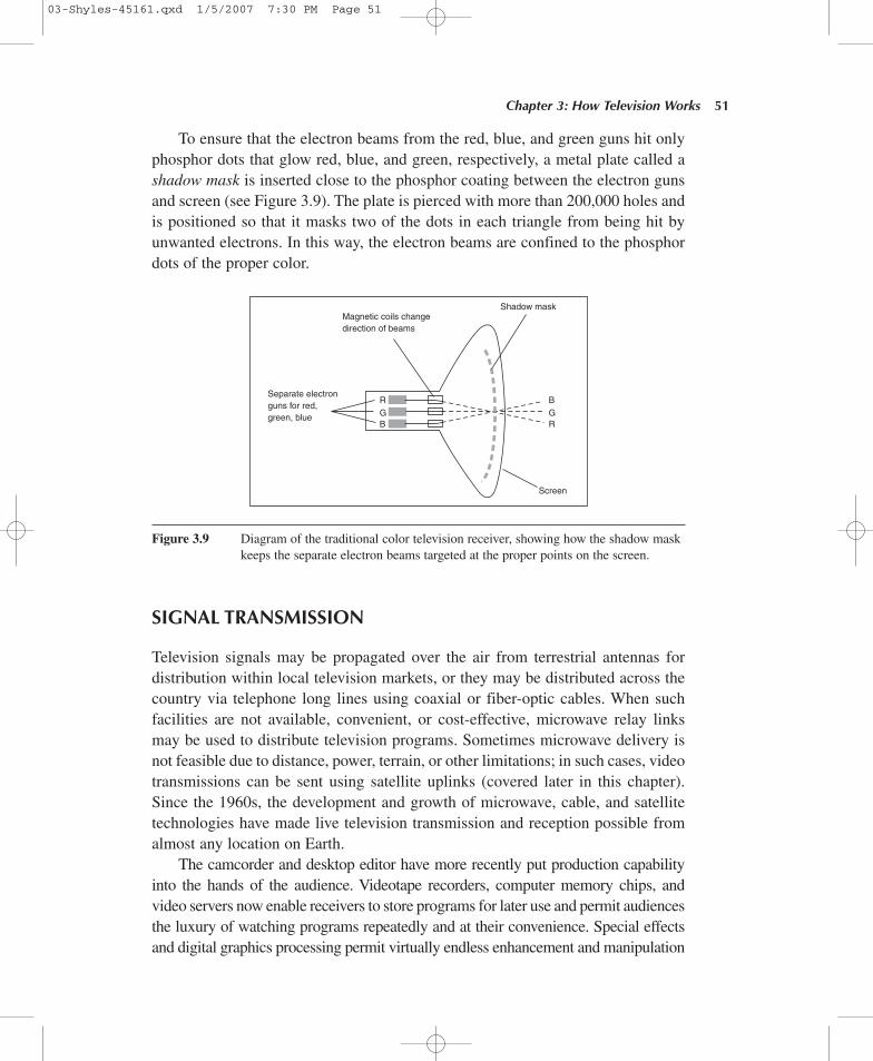
To ensure that the electron beams from the red, blue, and green guns hit onlyphosphor dots that glow red, blue, and green, respectively, a metal plate called ashadow mask is inserted close to the phosphor coating between the electron gunsand screen (see Figure 3.9). The plate is pierced with more than 200,000 holes andis positioned so that it masks two of the dots in each triangle from being hit byunwanted electrons. In this way, the electron beams are confined to the phosphordots of the proper color.
Chapter 3: How Television Works 51
Separate electronguns for red,green, blue
RGB
BGR
Magnetic coils changedirection of beams
Shadow mask
Screen
Figure 3.9 Diagram of the traditional color television receiver, showing how the shadow maskkeeps the separate electron beams targeted at the proper points on the screen.
SIGNAL TRANSMISSION
Television signals may be propagated over the air from terrestrial antennas fordistribution within local television markets, or they may be distributed across thecountry via telephone long lines using coaxial or fiber-optic cables. When suchfacilities are not available, convenient, or cost-effective, microwave relay linksmay be used to distribute television programs. Sometimes microwave delivery isnot feasible due to distance, power, terrain, or other limitations; in such cases, videotransmissions can be sent using satellite uplinks (covered later in this chapter).Since the 1960s, the development and growth of microwave, cable, and satellitetechnologies have made live television transmission and reception possible fromalmost any location on Earth.
The camcorder and desktop editor have more recently put production capabilityinto the hands of the audience. Videotape recorders, computer memory chips, andvideo servers now enable receivers to store programs for later use and permit audiencesthe luxury of watching programs repeatedly and at their convenience. Special effectsand digital graphics processing permit virtually endless enhancement and manipulation
03-Shyles-45161.qxd 1/5/2007 7:30 PM Page 51
of video images. High-quality audio and multiple speaker configurations offer stereoand surround sound for consumers’ home entertainment systems. Interactive systemsenable users to engage in dialogue with program providers and with one another.Projection and big-screen video as well as flat-screen displays, including bothplasma display panels (PDPs) and liquid crystal displays (LCDs), now influencehomebuilders and realtors to feature entertainment theater space as a selling pointin marketing homes. The remote control continues to influence the way we watchtelevision, as well as influencing the way programmers think about how to capture ourattention.
Since the advent of television, technical developments have continued to maketelevision more engaging than it was in its infancy. Yet the core of the system stilluses radio energy to broadcast television signals. However, the picture is changingright before our eyes. We are witnessing a profound transition from analog to digi-tal platforms, as well as a convergence of broadcasting, computer, and telecommu-nication technologies. What is the result? An explosion of interactive informationand entertainment services to American households and beyond. The new orderenables us to originate our own programming if we wish. The age of interactive dig-ital television (DTV) is upon us. What are some of the implications of this change?
THE ADOPTION OF ADIGITAL TELEVISION (DTV) STANDARD
On December 24, 1996, the Federal Communications Commission (FCC)announced its decision to adopt a digital television standard for a free, universallyavailable digital broadcast television service for America. Originally, the maingoal of developing an advanced television system was to provide America withhigher quality video images, known as high-definition television (HDTV orHD). However, rapid development of digital technologies has expanded the objec-tives of public interest groups, computer and television manufacturers, telecom-munication providers, cable and satellite interests, filmmakers, broadcasters, andothers interested in enhanced video services.
Beyond HD, the DTV age now implies expanded applications to include movieson demand, telephone and computer data delivery, interactive programming, dis-tance learning, paging systems, home shopping and e-commerce applications, videoproduction and editing, and so on.
Understanding the public policy and economic interests behind DTV develop-ment is key to understanding the technical configuration of the new system. Amongthe goals of the FCC was to adopt a “world leading digital broadcast televisiontechnology” that would
52 P A R T I : C O M M U N I C A T I N G W I T H V I D E O
03-Shyles-45161.qxd 1/5/2007 7:30 PM Page 52
1. put more video program choices into the hands of American consumers,
2. provide better quality audio and video than that available with the NTSCsystem,
3. provide innovative services due to data transmission capability, and
4. offer compatibility (interoperability) between video and computer technol-ogy to spur innovation and competition.
To achieve these goals, the FCC began inquiries in 1987 into the potential foradvanced television (ATV) services. At that time, industry research teams sug-gested more than 20 systems. In February 1993, after determining that any systemto be adopted would be fully digital, four such systems were considered.
In May 1993, seven companies and institutions representing the four remain-ing systems formed a “grand alliance” to develop a “best of the best” single sys-tem to present to the FCC for approval. Over the next two and a half years, a finaldigital system was developed, tested, documented, and recommended to the FCC.In December 1996, the system was approved.
The Advanced Television System Committee (ATSC), composed of a 54-member group including television workers, television and film producers, tradeassociations, television and equipment manufacturers, and segments of the acade-mic community, has endorsed the newly adopted DTV system as “the best digitalbroadcast television system in the world.” The ATSC has characterized the systemas having unmatched flexibility and ability to incorporate future improvements.However, some industry parties have voiced objections about having the govern-ment impose the standard. Some at the time questioned whether it might be betterto allow market forces to dictate standards rather than have the government inter-vene. Some suggested having the government issue standards only for spectrumallocation, transmission, and reception, to avoid interference problems, but toleave all other conditions (e.g., frame rates, number of scanning lines, aspect ratioof the screen) open. Ultimately, the FCC decided that letting market forces deter-mine standards would lead to the development of incompatible systems that wouldbe too costly to consumers who might have to invest in several different receiversto gain access to different programs. Incompatible systems might also require theuse of set-top boxes, translation devices, and other interface hardware and soft-ware that might slow down encoding, transmission, and decoding of data streams,thus degrading the efficiency of the entire system. In addition, the FCC reasonedthat a government-mandated standard would be the best way to guarantee univer-sal access to broadcasting services for all Americans. The FCC viewed broadcast-ing as unique, free, and available to nearly every American who relies on it as a
Chapter 3: How Television Works 53
03-Shyles-45161.qxd 1/5/2007 7:30 PM Page 53
primary source of information and entertainment. Because of these characteristics,the FCC reasoned that the goals of certainty and reliability take on a special sig-nificance and strengthen the case for the adoption of a government-imposed DTVstandard. Finally, the FCC reasoned that allowing different standards to developmight make the conversion process from the current analog system to a fully dig-ital service more difficult. For these reasons, letting the market drive the selectionof a standard was rejected.
To make the DTV standard as industry-friendly as possible, the FCC invitedstandards to be developed by industry parties. In this way, it was believed the DTVsystem that developed would better reflect industry needs. For this reason, thestandard is called “voluntary.”
Characteristics of the New Standard
Like the NTSC television format, the new DTV standard calls for each televisionchannel to occupy a 6-MHz bandwidth. To fit the more complex digital signaldemands of DTV (at times with many times the picture resolution of the currentNTSC format) into the same space used for current analog signals, digital com-pression techniques (described in more detail later) are used. However, unlikethe NTSC format that uses only interlaced scanning of 525 lines at 30 frames persecond on a screen three units high by four units wide, DTV remains relativelyflexible on these dimensions.
For example, to promote compatibility (interoperability) with other services,including rerunning archives of NTSC programs, newer telecommunication andcomputer-based media, and film formats, the DTV standard can broadcast andreceive both interlace-scanned programs and those produced in a new noninter-laced scanning format called progressive scanning. In progressive scanning,each line is scanned in order, with no skipping, at a maximum rate of 60 framesper second (double the current NTSC frame rate).
The new system accommodates both the traditional NTSC horizontal lineformat as well as some newer ones. Currently, the NTSC format is fixed at525 lines of pixels distributed in a rectangular arrangement. In this design, thedistance between pixels is greater horizontally than vertically. However, in thenew system, a maximum of 1,080 horizontal lines of pixels will be featured in asquare arrangement; that is, pixels will be equally spaced in horizontal and ver-tical directions. As a result, new receivers will be compatible with both NTSCformat programs as well as many computer displays.
The two new line formats in the DTV standard include one with 720 horizon-tal lines per frame and one with 1,080 lines per frame in a 16:9 aspect ratio ofwidth to height.
54 P A R T I : C O M M U N I C A T I N G W I T H V I D E O
03-Shyles-45161.qxd 1/5/2007 7:30 PM Page 54
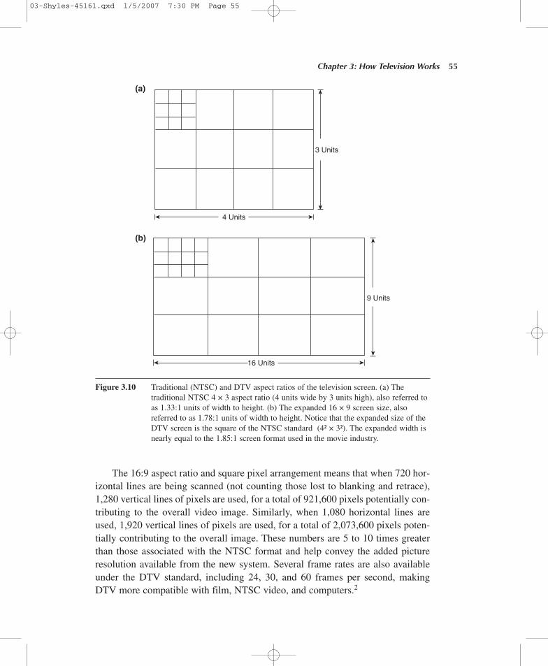
The 16:9 aspect ratio and square pixel arrangement means that when 720 hor-izontal lines are being scanned (not counting those lost to blanking and retrace),1,280 vertical lines of pixels are used, for a total of 921,600 pixels potentially con-tributing to the overall video image. Similarly, when 1,080 horizontal lines areused, 1,920 vertical lines of pixels are used, for a total of 2,073,600 pixels poten-tially contributing to the overall image. These numbers are 5 to 10 times greaterthan those associated with the NTSC format and help convey the added pictureresolution available from the new system. Several frame rates are also availableunder the DTV standard, including 24, 30, and 60 frames per second, makingDTV more compatible with film, NTSC video, and computers.2
Chapter 3: How Television Works 55
4 Units
16 Units
9 Units
3 Units
(a)
(b)
Figure 3.10 Traditional (NTSC) and DTV aspect ratios of the television screen. (a) Thetraditional NTSC 4 × 3 aspect ratio (4 units wide by 3 units high), also referred toas 1.33:1 units of width to height. (b) The expanded 16 × 9 screen size, alsoreferred to as 1.78:1 units of width to height. Notice that the expanded size of theDTV screen is the square of the NTSC standard (4² × 3²). The expanded width isnearly equal to the 1.85:1 screen format used in the movie industry.
03-Shyles-45161.qxd 1/5/2007 7:30 PM Page 55
Finally, the 16:9 aspect ratio provided by DTV is more compatible with theformat used in many films produced throughout the world, and with flexibleletterboxing capability, presenting programs produced in aspect ratios differentfrom the 16:9 format becomes easy. Letterboxing is a technique used to preservethe original aspect ratio of a film by blacking out portions of the screen, usually atthe top and bottom. Film content is not cut from the frame. With letterboxing, thecomplete frame is transmitted, and no parts of the picture are left out.
In addition to these characteristics, new system capabilities include the following:
1. Layering of video and audio signals that enables multiplexing and transportof different programs simultaneously over the same channel. For example,layering makes it possible to broadcast two HD programs at the same timeor “multicast” (transmit multiple data streams) several standard definitiontelevision (SDTV) programs at a visual quality better than that currentlyavailable. Current estimates claim that more than five such programs ordozens of CD-quality audio signals can be multicast simultaneously.
2. RF transmission.
3. Rapid delivery of large amounts of data (e.g., the contents of the dailynewspaper could be sent in less than two seconds).
4. Capability for interactive transmission of educational materials.
5. Provision for universal closed-captioning for the deaf.
With all of these developments, it is clear that DTV will continue to expandthe power, pervasiveness, and influence of television. As new configurationsbecome available, it will become increasingly important for message makers andconsumers to understand how new devices may be used to reach and influenceaudiences and how audiences will use them for their own ends.
Satellite communication, cellular telephones, and microwave links carryingfaxes, e-mails, and computer databases all depend on wireless transmission ofmodulated radio signals to connect distant users. Without these infrastructures,millions now on the wireless network would be isolated from one another. As longas we use radio energy to send data representing sounds and images across spaceat the speed of light, it will be necessary to know how broadcasting works to havea full understanding of digital media. Understanding how broadcasting systemsoperate is one of the essentials.
COMPUTERS AND TELECOMMUNICATIONS IN VIDEO
In addition to understanding how broadcasting systems operate, it is also essentialfor you to understand how computers and telecommunications systems contribute
56 P A R T I : C O M M U N I C A T I N G W I T H V I D E O
03-Shyles-45161.qxd 1/5/2007 7:30 PM Page 56
to the video production process. Perhaps most obvious is the role of computersin creating special effects in postproduction editing (for both audio and video).Simply put, virtually all video editing is now done on computers, from networkshops to small independent producers; even Hollywood has adopted digital edit-ing for first-run films.
Less obvious is the role of these systems in video distribution, another phase ofpostproduction. In this application, distant users can share computer files of videoprograms, over both wire and wireless channels, with a computer, a fiber or phoneconnection, and an e-mail address. While this raises important copyright issues andunderscores the vulnerability exhibitors face from media pirates, the convenienceof such options makes the use of computers (combined with telecommunicationchannels) for rapid distribution of media products too attractive to ignore.
Computers are now also central to shooting video. For example, in the pro-duction phase, digital cameras record sounds and images as digital data, throughan encoding process known as sampling and quantizing (explained later). Inaddition, because digital cameras record video and sound as data files, programscan be sent to computer servers immediately from multiple locations either forbroadcast or further processing (i.e., editing) without losing signal quality; filescan also be sent over any size channel (broadband or narrowband) either in onecontinuous transmission or in discrete bursts, again without signal loss. Analogvideo either falls short or can’t do any of these things.
Besides offering videographers greater reliability, digital cameras are alsolighter in weight than their analog counterparts, have longer battery life than everbefore, and require lower light levels to record air-quality material. In marketingterms (a concern during every phase of production), digital encoding offers addi-tional advantages, including the ability to embed extra information about pro-grams regarding production dates, ratings, personnel involved, additional content(i.e., outtakes stored as separate chapter content), and other information designedto attract or advise consumers.
Clearly, computers and telecommunications channels are involved in everyphase of video production from shooting and editing to distribution and market-ing, making it critical to know as much as possible about how these technologiescontribute to the process. The remainder of this chapter explains how computersand telecommunications infrastructures work, in both conceptual and physicalterms relevant to the production setting.
Computers
How do computers enable users to create (encode) and display (decode) video infor-mation? In computers, the main substance acted on by electrical signals for codingand storing video information is silicon, a naturally occurring element.3 When treated
Chapter 3: How Television Works 57
03-Shyles-45161.qxd 1/5/2007 7:30 PM Page 57
with other materials, silicon can be used to encode, store, and manipulate any kindof information, including video images and sound. To explain how computers makethis possible, you should know first how binary code may be used to represent anykind of information and then, from both conceptual and physical perspectives, howcomputers may be used to make, store, and retrieve television programs.
Using binary code to render and store information predates modern digitalcomputers by centuries. Simply put, binary code uses just two symbols to recordinformation. Remember, it is essential to vary some aspect of a signal for it to carrya message. This is because some variation or modulation is required to impose apattern of intelligence on any medium; otherwise, no message can be encoded.4
The Binary Number System
Around 1900, telegraphers began using Morse code to communicate to distantplaces without wires (wireless telegraphy) by propagating patterns of radio energyin long and short bursts to represent the letters of the alphabet. This was one of theearliest uses of binary code in a broadcast setting.
Beyond language functions, binary code can also be used to express anynumerical value and perform mathematical calculations. The ability of binary codeto capture both verbal and mathematical ideas is extraordinarily important becauseit shows how any type and amount of information that can be expressed may berendered into numerical code using only 0s and 1s. In other words, although thebinary number system uses only two symbols, it is completely versatile. For exam-ple, decimal numbers (so called because they use 10 symbols, from 0 through 9)may be expressed in binary form, as shown in Figure 3.11.
Notice that when the supply of digits runs out, decimal numbers move oneplace to the left, where they are used all over again in a new column at an increasedpower of 10. In binary, the same practice is followed, but with one difference:When the numbers move over, they increase in value by powers of only 2. So, asFigure 3.11 shows, the number 10 in the decimal system is expressed as 1010 inbinary, where the digit “0” on the far right tells us there are no 1s, the digit next toit tells us there is one 2, the next that there are no 4s, and the last on the far leftthat there is one 8, for a total of 10 (decimal), and so on.
Notice that as places move from right to left in the decimal system, decimalvalues increase tenfold (i.e., place values go from 1s to 10s to hundreds to thou-sands, etc.), whereas when places move in the binary system, values increase bypowers of only 2 (i.e., from 1s to 2s to 4s to 8s, etc.). Nevertheless, using binarycode, it is possible to represent any number.
Binary code is difficult for human beings to use because long strings of repeat-ing 0s and 1s can quickly challenge our perceptual systems, as the binary numberrepresenting the number 256 illustrates (see Figure 3.11). But it is just the opposite
58 P A R T I : C O M M U N I C A T I N G W I T H V I D E O
03-Shyles-45161.qxd 1/5/2007 7:30 PM Page 58
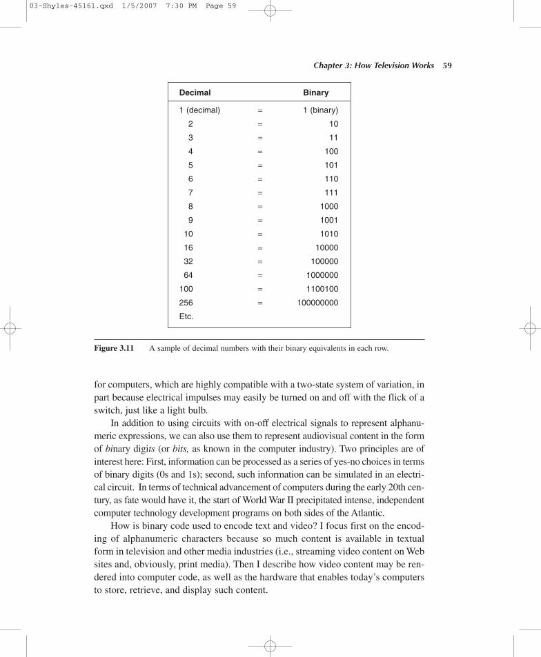
for computers, which are highly compatible with a two-state system of variation, inpart because electrical impulses may easily be turned on and off with the flick of aswitch, just like a light bulb.
In addition to using circuits with on-off electrical signals to represent alphanu-meric expressions, we can also use them to represent audiovisual content in the formof binary digits (or bits, as known in the computer industry). Two principles are ofinterest here: First, information can be processed as a series of yes-no choices in termsof binary digits (0s and 1s); second, such information can be simulated in an electri-cal circuit. In terms of technical advancement of computers during the early 20th cen-tury, as fate would have it, the start of World War II precipitated intense, independentcomputer technology development programs on both sides of the Atlantic.
How is binary code used to encode text and video? I focus first on the encod-ing of alphanumeric characters because so much content is available in textualform in television and other media industries (i.e., streaming video content on Websites and, obviously, print media). Then I describe how video content may be ren-dered into computer code, as well as the hardware that enables today’s computersto store, retrieve, and display such content.
Chapter 3: How Television Works 59
Decimal Binary
1 (decimal) = 1 (binary)
2 = 10
3 = 11
4 = 100
5 = 101
6 = 110
7 = 111
8 = 1000
9 = 1001
10 = 1010
16 = 10000
32 = 100000
64 = 1000000
100 = 1100100
256 = 100000000
Etc.
Figure 3.11 A sample of decimal numbers with their binary equivalents in each row.
03-Shyles-45161.qxd 1/5/2007 7:30 PM Page 59
ASCII: Why “1” Is a Beautiful Number in the Computer World
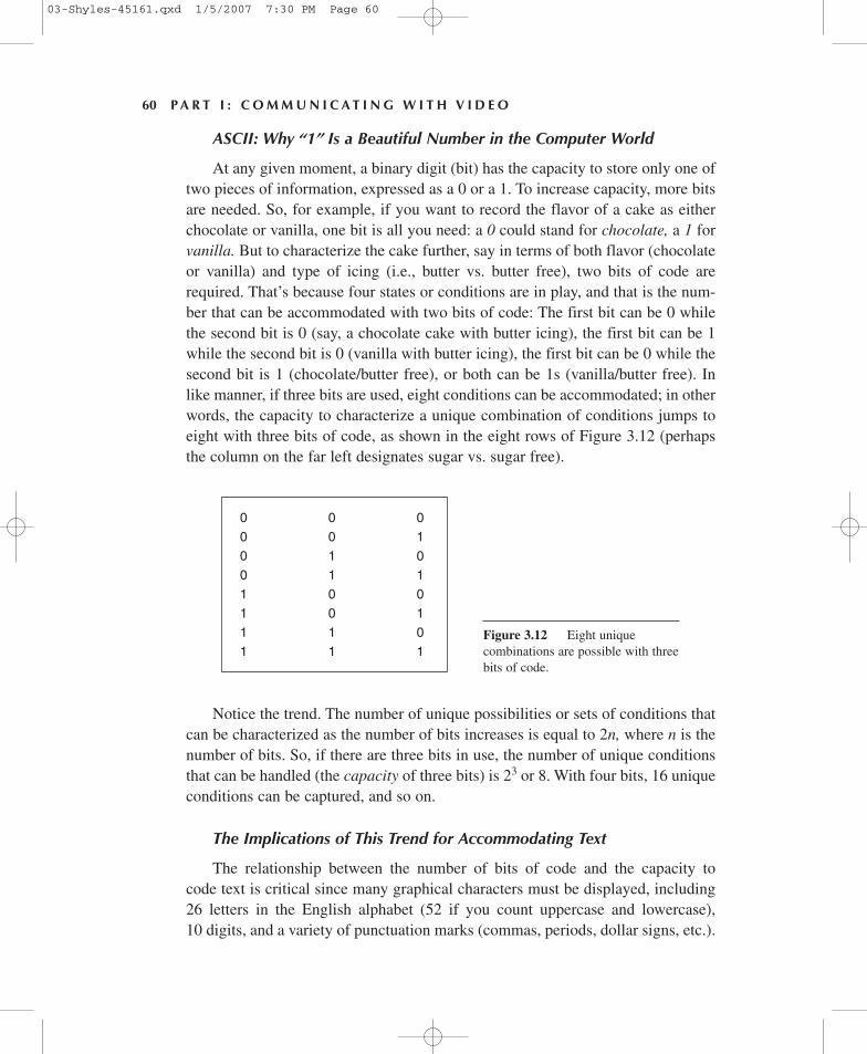
At any given moment, a binary digit (bit) has the capacity to store only one oftwo pieces of information, expressed as a 0 or a 1. To increase capacity, more bitsare needed. So, for example, if you want to record the flavor of a cake as eitherchocolate or vanilla, one bit is all you need: a 0 could stand for chocolate, a 1 forvanilla. But to characterize the cake further, say in terms of both flavor (chocolateor vanilla) and type of icing (i.e., butter vs. butter free), two bits of code arerequired. That’s because four states or conditions are in play, and that is the num-ber that can be accommodated with two bits of code: The first bit can be 0 whilethe second bit is 0 (say, a chocolate cake with butter icing), the first bit can be 1while the second bit is 0 (vanilla with butter icing), the first bit can be 0 while thesecond bit is 1 (chocolate/butter free), or both can be 1s (vanilla/butter free). Inlike manner, if three bits are used, eight conditions can be accommodated; in otherwords, the capacity to characterize a unique combination of conditions jumps toeight with three bits of code, as shown in the eight rows of Figure 3.12 (perhapsthe column on the far left designates sugar vs. sugar free).
60 P A R T I : C O M M U N I C A T I N G W I T H V I D E O
0 0 00 0 10 1 00 1 11 0 01 0 11 1 01 1 1
Figure 3.12 Eight uniquecombinations are possible with threebits of code.
Notice the trend. The number of unique possibilities or sets of conditions thatcan be characterized as the number of bits increases is equal to 2n, where n is thenumber of bits. So, if there are three bits in use, the number of unique conditionsthat can be handled (the capacity of three bits) is 23 or 8. With four bits, 16 uniqueconditions can be captured, and so on.
The Implications of This Trend for Accommodating Text
The relationship between the number of bits of code and the capacity tocode text is critical since many graphical characters must be displayed, including26 letters in the English alphabet (52 if you count uppercase and lowercase),10 digits, and a variety of punctuation marks (commas, periods, dollar signs, etc.).
03-Shyles-45161.qxd 1/5/2007 7:30 PM Page 60
In addition, a number of control commands provide syntax to control the layoutof the graphical content, including spacing between words and sentences, taband backspace commands, and so on. Clearly, four bits of code are not enough tohandle all that since more than 16 characters are included in just one case of thealphabet alone. How many bits should be set aside for alphanumeric text?
In 1967, this question was answered in the United States when the AmericanStandard Code for Information Interchange, or ASCII (rhymes with “gas key”),was developed. It calls for a seven-bit code standard for alphanumeric characters.With seven bits available, you can manipulate 128 unique items of information,which is enough capacity to accommodate all the letters of the alphabet (bothuppercase and lowercase), all 10 digits, punctuation marks, and so on.
Adopting a single standard simplifies information exchange among computers.By using ASCII code, computers can share information without translation (a hugeadvantage). That is why the heading of this section calls 1 a beautiful number in thecomputer industry: An agreed-on standard simplifies information sharing.
At the time ASCII was developed, computer memory was both limited andcostly, but it was obvious that a six-bit code lacked the capacity to handle alphanu-meric text. So a seven-bit architecture was adopted. As it turns out, however,almost all computer systems today are based on an eight-bit architecture (eacheight-bit chunk is called a byte); that is, information is stored in chunks of eight-bit bytes, even ASCII code.
Capturing Sound and Video With Binary Code
ASCII code is great for coding text, but it is too limited for handling sound orimages. How is binary code used to capture sound?
Sound is an analog phenomenon; that is, it is a continuous stream of infor-mation, usually made up of waves of compressed air that cause the generatingelement of a microphone or your eardrums to vibrate sympathetically. In analogrecording, physical sound vibrations are converted into a pattern of electricalsignals matching the original stimulus (a process called transduction).
By contrast, in digital recording, or in the conversion of the voice, say, for cellu-lar telephone transmission, binary numbers are used to represent the varying fluctua-tions of electricity generated by sound waves through a process of sampling andquantization. To do this, the pattern of electricity matching sound signals is convertedinto a digital data stream using an analog-to-digital converter. How does this happen?
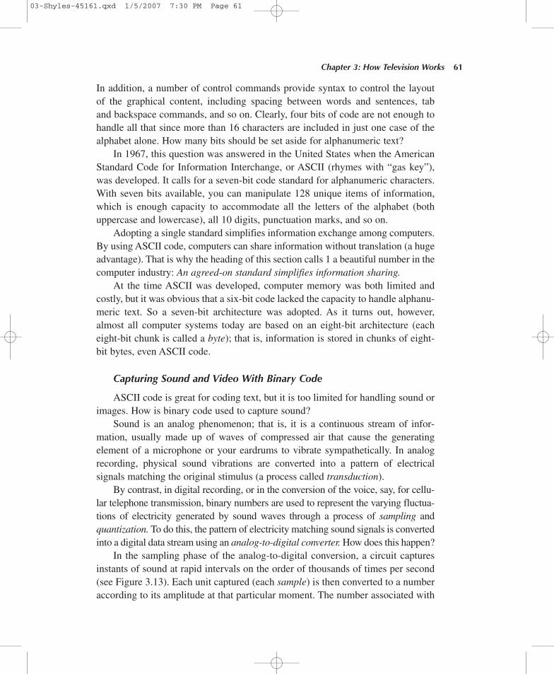
In the sampling phase of the analog-to-digital conversion, a circuit capturesinstants of sound at rapid intervals on the order of thousands of times per second(see Figure 3.13). Each unit captured (each sample) is then converted to a numberaccording to its amplitude at that particular moment. The number associated with
Chapter 3: How Television Works 61
03-Shyles-45161.qxd 1/5/2007 7:30 PM Page 61
62 P A R T I : C O M M U N I C A T I N G W I T H V I D E O
1.0
0.5
0
–0.5
–1.0
Samples
Samples
Waveform
Figure 3.13 Illustration of the sampling phase of the analog-to-digital conversion.
each sample is then stored in binary form. Figure 3.13 illustrates this part of theanalog-to-digital conversion process.
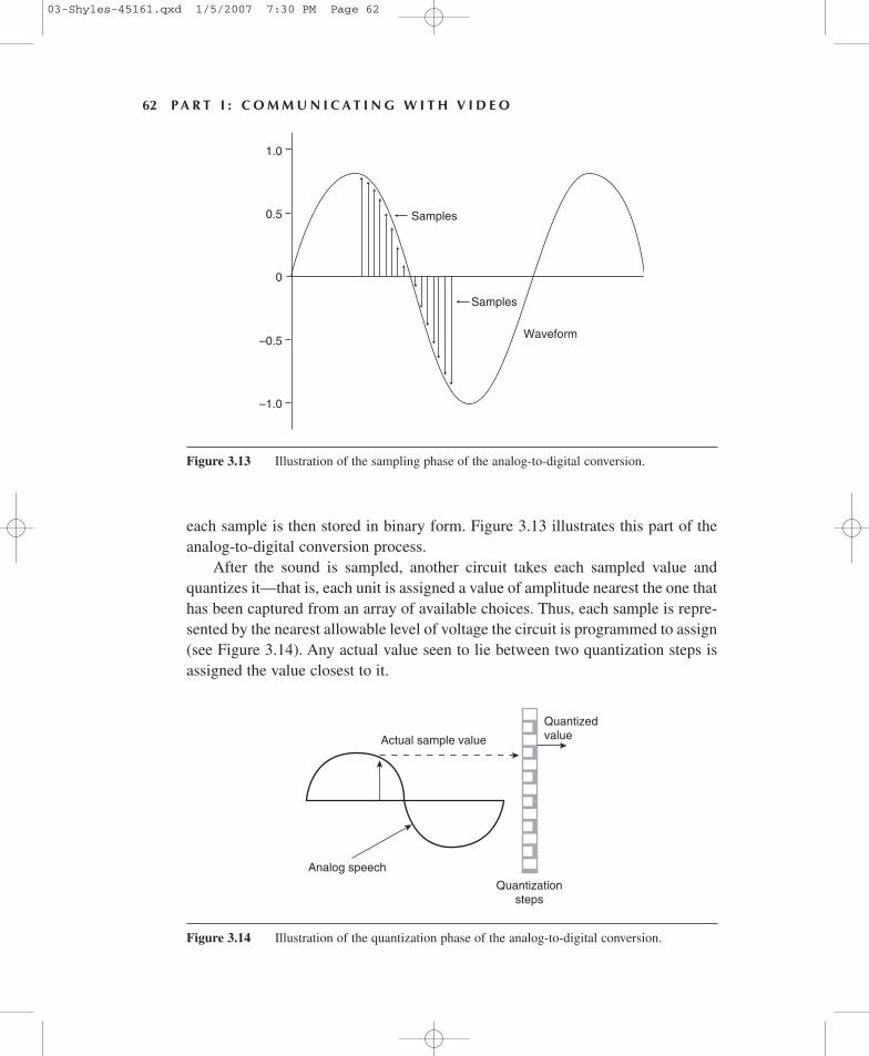
After the sound is sampled, another circuit takes each sampled value andquantizes it—that is, each unit is assigned a value of amplitude nearest the one thathas been captured from an array of available choices. Thus, each sample is repre-sented by the nearest allowable level of voltage the circuit is programmed to assign(see Figure 3.14). Any actual value seen to lie between two quantization steps isassigned the value closest to it.
Analog speech
Actual sample value
Quantizedvalue
Quantizationsteps
Figure 3.14 Illustration of the quantization phase of the analog-to-digital conversion.
03-Shyles-45161.qxd 1/5/2007 7:30 PM Page 62
In the case of compact disk (CD) recordings, where fidelity is of paramountimportance, and transmission and bandwidth matters are not an issue, a greaternumber of samples quantized more finely may be used than, say, in the cell phoneindustry, where transmission and bandwidth issues are critical.
In all cases, once samples have been quantized, each bit of audio informationis placed into a sequence called a pulse train consisting of series of 0s and 1s rep-resenting the original sound, which is, at the receiving end, converted back intoelectrical signals through the use of a digital-to-analog converter. It is this signalthat is finally fed to your earpiece or amplifiers connected to the speakers of yourstereo system or television entertainment center.
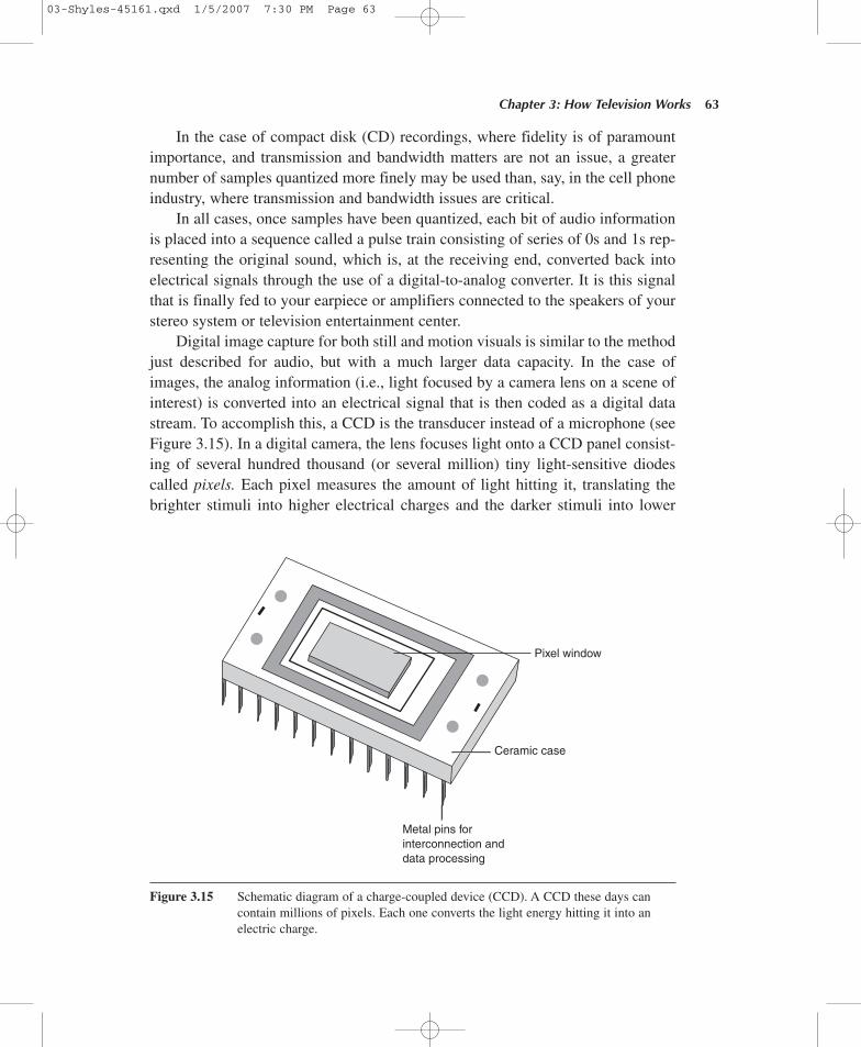
Digital image capture for both still and motion visuals is similar to the methodjust described for audio, but with a much larger data capacity. In the case ofimages, the analog information (i.e., light focused by a camera lens on a scene ofinterest) is converted into an electrical signal that is then coded as a digital datastream. To accomplish this, a CCD is the transducer instead of a microphone (seeFigure 3.15). In a digital camera, the lens focuses light onto a CCD panel consist-ing of several hundred thousand (or several million) tiny light-sensitive diodescalled pixels. Each pixel measures the amount of light hitting it, translating thebrighter stimuli into higher electrical charges and the darker stimuli into lower
Chapter 3: How Television Works 63
Ceramic case
Metal pins forinterconnection anddata processing
Pixel window
Figure 3.15 Schematic diagram of a charge-coupled device (CCD). A CCD these days cancontain millions of pixels. Each one converts the light energy hitting it into anelectric charge.
03-Shyles-45161.qxd 1/5/2007 7:30 PM Page 63
electrical charges. In this way, a mosaic of light intensities renders the originalscene, creating a faithful black-and-white image of it.
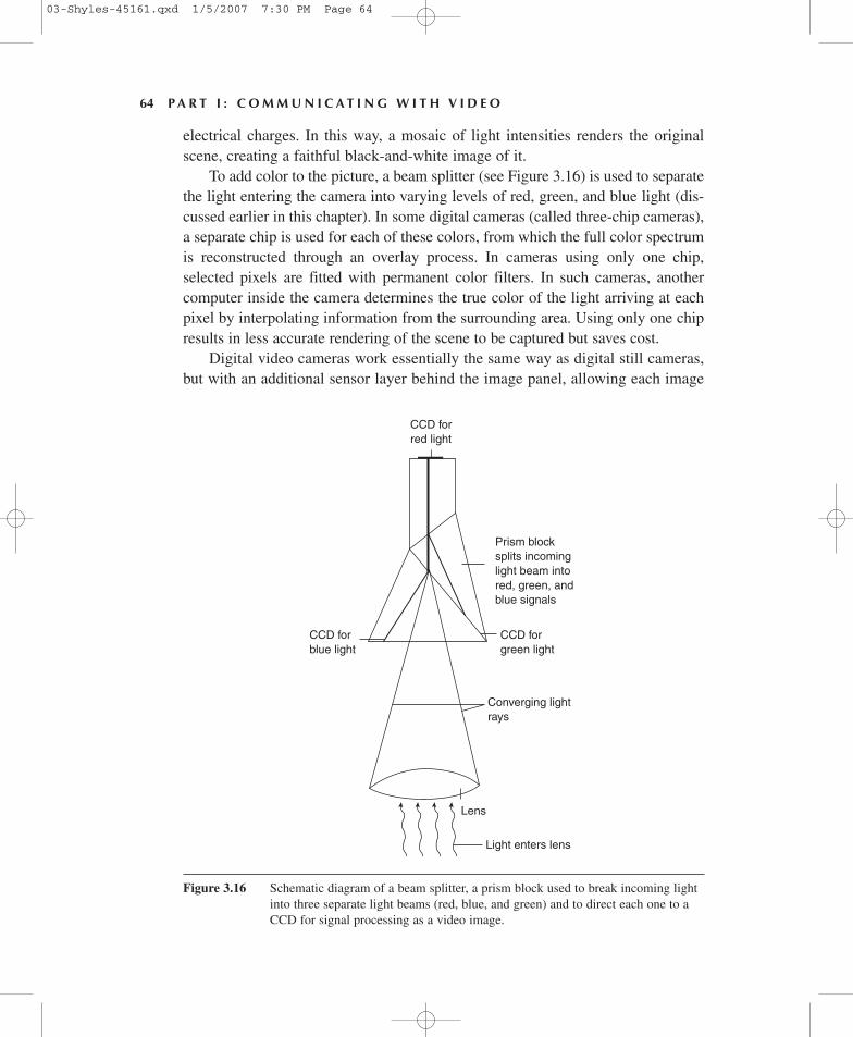
To add color to the picture, a beam splitter (see Figure 3.16) is used to separatethe light entering the camera into varying levels of red, green, and blue light (dis-cussed earlier in this chapter). In some digital cameras (called three-chip cameras),a separate chip is used for each of these colors, from which the full color spectrumis reconstructed through an overlay process. In cameras using only one chip,selected pixels are fitted with permanent color filters. In such cameras, anothercomputer inside the camera determines the true color of the light arriving at eachpixel by interpolating information from the surrounding area. Using only one chipresults in less accurate rendering of the scene to be captured but saves cost.
Digital video cameras work essentially the same way as digital still cameras,but with an additional sensor layer behind the image panel, allowing each image
64 P A R T I : C O M M U N I C A T I N G W I T H V I D E O
CCD forred light
CCD forblue light
CCD forgreen light
Converging lightrays
Prism blocksplits incominglight beam intored, green, andblue signals
Lens
Light enters lens
Figure 3.16 Schematic diagram of a beam splitter, a prism block used to break incoming lightinto three separate light beams (red, blue, and green) and to direct each one to aCCD for signal processing as a video image.
03-Shyles-45161.qxd 1/5/2007 7:30 PM Page 64
to be transferred to the second layer so that the first layer can refresh itself in orderto capture a series of images in rapid succession. This process happens many timesper second, creating the illusion of motion when replayed. Finally, the analogvisual images are digitized essentially the same way as sound, through a processof sampling, quantizing, and coding. In the sampling stage, a number of selectedinstants of the analog signal (measured in MHz rather than kHz) are captured.Then each is assigned a quantized value from among an array of choices. Then,the values are coded into binary number equivalents composed of sequences of 0sand 1s. In recovering the information to make it viewable again, a reversal of thisprocess is accomplished through a digital-to-analog conversion.
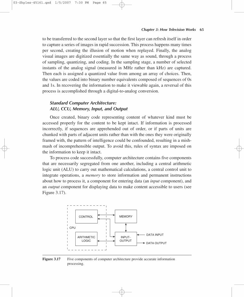
Standard Computer Architecture:ALU, CCU, Memory, Input, and Output
Once created, binary code representing content of whatever kind must beaccessed properly for the content to be kept intact. If information is processedincorrectly, if sequences are apprehended out of order, or if parts of units arechunked with parts of adjacent units rather than with the ones they were originallyframed with, the pattern of intelligence could be confounded, resulting in a mish-mash of incomprehensible output. To avoid this, rules of syntax are imposed onthe information to keep it intact.
To process code successfully, computer architecture contains five componentsthat are necessarily segregated from one another, including a central arithmeticlogic unit (ALU) to carry out mathematical calculations, a central control unit tointegrate operations, a memory to store information and permanent instructionsabout how to process it, a component for entering data (an input component), andan output component for displaying data to make content accessible to users (seeFigure 3.17).
Chapter 3: How Television Works 65
CPU
CONTROL
ARITHMETICLOGIC
MEMORY
INPUT-OUTPUT
DATA INPUT
DATA OUTPUT
Figure 3.17 Five components of computer architecture provide accurate informationprocessing.
03-Shyles-45161.qxd 1/5/2007 7:30 PM Page 65
Input components include such items as the keyboard and computer mouse, butthose are not the only ones. Others include pressure-sensitive touch screens, suchas those seen in restaurants, and plastic pens used to enter data on handheld PCs.Common output components include RGB video monitors and computer screens,printers, audio speakers, telephone earpieces, and headphones, among others.
The five-component computer architecture is still in use today. In addition, thecomputer’s operations are performed in sequence one at a time (an imposition of tem-poral order to guard further against confusion), using a clock chip to order operations.
Computer systems may be programmed to control complicated and varied setsof conditions, exhibiting what has come to be called artificial intelligence (AI). Insuch systems, binary code may be used to execute an array of preset instructionsdesigned to alter incoming information with a wide variety of practical benefits.
One application of such technology in the television industry is seen in the useof the V-Chip, a computer device required by FCC rules to be installed on all televi-sion sets 13 inches or larger manufactured after January 1, 2000. Thanks to digitaltext embedded as header information in most television programs, the V-Chip canread the ratings information associated with a show and then block the program fromdisplay if deemed undesirable by the user based on a set of instructions.
From Tubes to Transistors
As mentioned earlier, the ability of triode vacuum tubes to perform signal-processing functions made it a versatile electronics tool, especially in broadcasting,telecommunication industries, and computer technology. But as mentioned, vacuumtubes were not perfect; they were large, hot, electricity hogs and unreliable—theyquickly burned out. When thousands of them were crammed in a box, as was oftenthe case in early computer manufacturing, the temperature inside could soon exceed120 degrees F. Such conditions required too much maintenance. Something betterwas needed. Something cooler. More reliable. Smaller. Less piggish.
By the late 1940s, alternative computer technology in the form of smaller,lighter, more reliable semiconductors was under development at AT&T and BellLaboratories. Semiconductors could conduct an electric current, performing thesame work as vacuum tubes but without the heat and with far less electricity con-sumption. Semiconductor technology gave rise to the first reliable solid-state tran-sistors (called so because, depending on the electrical conditions presented tothem, they acted as either a transmitter or a resistor of electric current).
Transistors could do everything vacuum tubes could do but without any of thetube’s shortcomings—no overheating, no breakable glass or filaments, no overcon-sumption of electricity. Transistors were everything vacuum tubes were not—theywere small, cool, light, and reliable. Their tiny size meant their electric signals had
66 P A R T I : C O M M U N I C A T I N G W I T H V I D E O
03-Shyles-45161.qxd 1/5/2007 7:30 PM Page 66
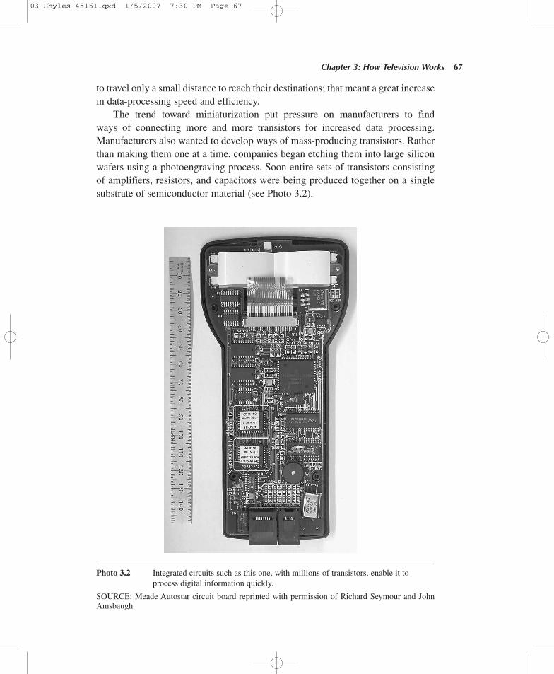
to travel only a small distance to reach their destinations; that meant a great increasein data-processing speed and efficiency.
The trend toward miniaturization put pressure on manufacturers to findways of connecting more and more transistors for increased data processing.Manufacturers also wanted to develop ways of mass-producing transistors. Ratherthan making them one at a time, companies began etching them into large siliconwafers using a photoengraving process. Soon entire sets of transistors consistingof amplifiers, resistors, and capacitors were being produced together on a singlesubstrate of semiconductor material (see Photo 3.2).
Chapter 3: How Television Works 67
Photo 3.2 Integrated circuits such as this one, with millions of transistors, enable it toprocess digital information quickly.
SOURCE: Meade Autostar circuit board reprinted with permission of Richard Seymour and JohnAmsbaugh.
03-Shyles-45161.qxd 1/5/2007 7:30 PM Page 67
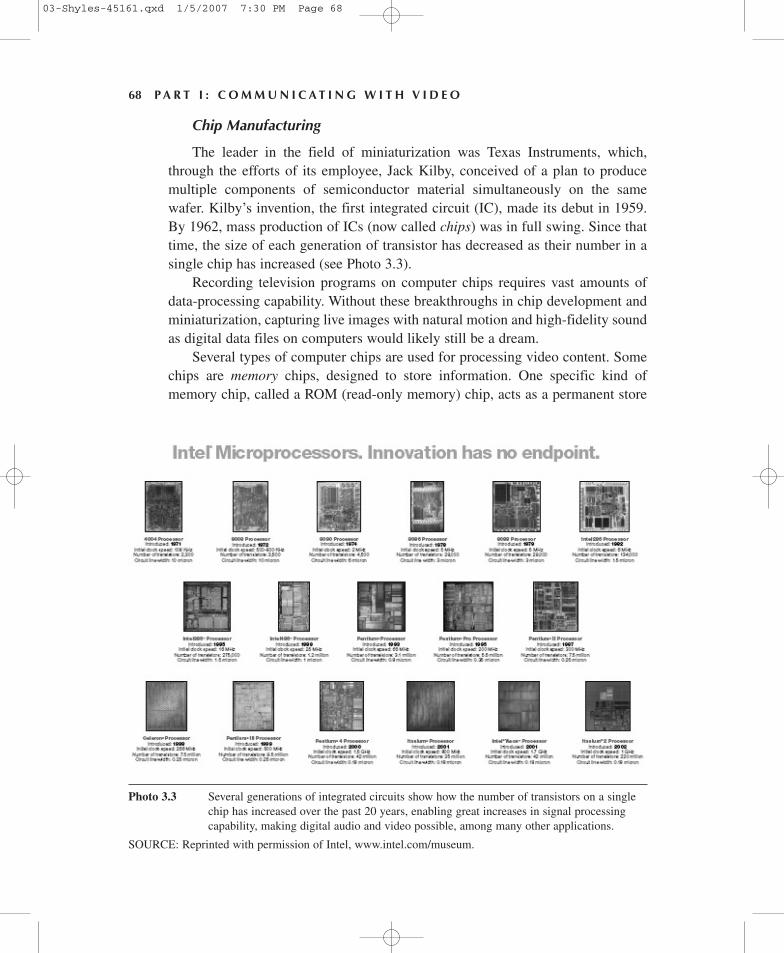
Chip Manufacturing
The leader in the field of miniaturization was Texas Instruments, which,through the efforts of its employee, Jack Kilby, conceived of a plan to producemultiple components of semiconductor material simultaneously on the samewafer. Kilby’s invention, the first integrated circuit (IC), made its debut in 1959.By 1962, mass production of ICs (now called chips) was in full swing. Since thattime, the size of each generation of transistor has decreased as their number in asingle chip has increased (see Photo 3.3).
Recording television programs on computer chips requires vast amounts ofdata-processing capability. Without these breakthroughs in chip development andminiaturization, capturing live images with natural motion and high-fidelity soundas digital data files on computers would likely still be a dream.
Several types of computer chips are used for processing video content. Somechips are memory chips, designed to store information. One specific kind ofmemory chip, called a ROM (read-only memory) chip, acts as a permanent store
68 P A R T I : C O M M U N I C A T I N G W I T H V I D E O
Photo 3.3 Several generations of integrated circuits show how the number of transistors on a singlechip has increased over the past 20 years, enabling great increases in signal processingcapability, making digital audio and video possible, among many other applications.
SOURCE: Reprinted with permission of Intel, www.intel.com/museum.
03-Shyles-45161.qxd 1/5/2007 7:30 PM Page 68
for binary code—that is, the transistor switches are set to react to electricity flowingthrough them the same way every time. It is like a file cabinet that simply holdsthe information (programs) inside.
Another type of chip is called a RAM (random-access memory) chip. RAMchips allow new information to be encoded and then deleted when no longerneeded. RAM chips allow transistor switches to create different patterns of elec-tric signals to flow, representing different types of information.
Yet another critically important type of chip is that which performs calculationsand makes logical decisions that control a computer’s activities in different parts ofthe machine. This chip is called the CPU (central processing unit) chip. Another isa clock chip that uses a quartz crystal to time operations so that all instructions arecarried out one at a time in proper sequence. Together, the various chips coordinateand execute computer operations to ensure that operations go as planned.
The modern digital computer, through the use of binary code and silicon chiptechnology, has made it possible for individuals to encode a wide variety of tex-tual and audiovisual messages that were once produced only by publishing houses,recording companies, and television studios. It is now a critical element of videoproduction.
But the ability to transmit such messages is not the result of computers.Rather, it is the integration of computers with broadcasting and telecommunica-tion infrastructures that permits program sharing and distribution to audiences.Without the telephone network and broadcasting technologies, computers wouldbe incapable of sharing information across wide areas. The next section explainshow computers are integrated with these older technologies to provide transmis-sion capability for the television industry and independent producers.
Telecommunications
Video transmission occurs through the integration of computers and other digitaldevices with broadcasting and telecommunication technologies. Without thepublic switched telephone network (PSTN) and similar (i.e., private) infrastruc-tures and broadcasting technologies, the immediate sharing of television programsamong distant users would be impossible.
This section explains how video programs are transmitted. A central topic isbandwidth, or the capacity of a channel to move digital information from oneplace to another in a given period of time. I describe some of the communicationtechnologies that transfer messages between points, including wire and cablefacilities (copper, coaxial, and fiber-optic), as well as wireless facilities using radioenergy (terrestrial microwave and satellite transmitters); all are currently used fortransmitting broadcast programming. I also describe how digitalization increases
Chapter 3: How Television Works 69
03-Shyles-45161.qxd 1/5/2007 7:30 PM Page 69
the capacity and flexibility of telecommunication channels. The topics includepacket switching, multiplexing, and signal compression, all designed to makemore efficient use of available bandwidth. I also outline some of the advantagesand disadvantages of digital versus analog modulation, as well as quality controlissues (i.e., error correction features) designed to ensure that programs receivedare the same as those that are sent.
Because analog television receivers are so plentiful in the United States, it willlikely be several years before we see a full transition to digital broadcasting. Thisis because set owners are often reluctant to invest in expensive new systems thatmay fail to become standard. Frequently, the adoption process is further slowed byincompatibilities across competing systems.
Of course, the digital revolution is still a work in progress. For example,twisted-pair copper wire, part of 19th-century telephone technology originallydesigned for analog voice traffic, is still in use today for connecting households totelephone exchange offices. At the same time, the network’s switching technologyhas been continually upgraded (from electromechanical relays to vacuum tubes todigital solid-state equipment) to increase efficiency. Since around 1990, however,telephone companies began carrying digital content in addition to analog voicetraffic through the adoption of 21st-century technologies not even dreamed ofwhen the phone system first developed, including T-1 and T-3 lines, optical fiberfor long-distance transmission, and digital subscriber lines (DSL), among others.
Today, the only part of the PSTN that has remained analog is the local loop(from homes to telephone exchange offices). And although existing copper wirehas been successfully adapted for many digital functions (e.g., both computer datatransmission and digital voice calls originating from cell phones must still becapable of reaching wire line phones through the local loop), the local infra-structure is not yet suitable for everything (i.e., broadband applications such astelevision-quality streaming video).
As a result, the current infrastructure still cannot deliver to most householdshigh-speed service for real-time interactive video and other products and servicesrequiring high capacity. Nevertheless, the eventual transition to a fully digitalsystem for broadcasting is inevitable.
With exceptions, digital transmission is a relatively recent phenomenon. Fordecades, our major commercial television networks distributed thousands of hoursof programming to hundreds of affiliate stations coast to coast in the form of ana-log video signals via high-bandwidth coaxial cable provided by the telephonecompany. The first such transcontinental distribution began in 1951, using AT&Tcoaxial cable to carry analog video signals.
But since the early 1990s, we have seen a transition from analog to digitaltransmission in both wire and wireless technologies. Why the change? What are
70 P A R T I : C O M M U N I C A T I N G W I T H V I D E O
03-Shyles-45161.qxd 1/5/2007 7:30 PM Page 70
the advantages of digital transmission that make it an attractive alternative for thetelevision industry over traditional analog service?
Digital transmission was really fostered by the development and success ofdigital computers—as you already know, binary code is the only kind of informa-tion computers can understand. However, the conversion from analog to digitalplatforms in the television industry is not merely the result of pressure to conformto the needs of computers; rather, it derives from the promise of a quantum leap incapacity (and, by implication, profits) that comes with digital delivery of productsand services.
Analog Versus Digital Signals
In the beginning of this section, I defined digital bandwidth as a measure of theamount of information that could pass through a communication channel in a givenperiod of time. However, in the early days of broadcasting (when the term band-width was first used), bandwidth was defined not as a measure of informationcapacity but simply as the frequency range assigned to a specific broadcastingchannel or service (e.g., short-wave radio, AM and FM radio, and, later, television).
Analog bandwidths were allocated according to both the physical limitationsof the broadcasting technologies available at the time they entered service and theintended functions of those services. Some services needed wider bandwidths thanothers to deliver acceptable signals. For example, television channels are biggerthan radio channels because they have to deliver both audio and video signals;therefore, they require greater bandwidth. Once assigned, analog spectrum alloca-tions were fixed; that is, analog radio channels provided just radio programs, tele-vision channels provided just television programs, and so on.
Today, we live in a very different world, with deep implications for the notionof bandwidth. Digital transmission permits a more flexible and efficient use ofbandwidth in both the electromagnetic spectrum and hardwire systems. First, dig-ital transmission is more flexible than analog because binary code, unlike analogsignals, can represent voice, text, data, images, and/or video, either alone or incombination with one another in any size channel and in any part of the frequencyspectrum. Therefore, the bandwidth used to carry digital information can be anysize, need not be restricted to just one type of service, and need not be limited tojust one part of the spectrum. Second, digital transmission can be sent withoutnoise or loss of fidelity, preserving original signal quality no matter how manytimes a program is transmitted. Third, digital transmissions are more efficient thananalog because, unlike analog signals, binary code can undergo data compressionwithout signal loss before being sent, allowing more information to be transmittedover the same channel in a given period of time.
Chapter 3: How Television Works 71
03-Shyles-45161.qxd 1/5/2007 7:30 PM Page 71
Furthermore, analog signals require a dedicated circuit large enough toaccommodate the signal being sent and must remain intact during transmissionto be received successfully. By contrast, digital signals may be sent over any typeof line, transmitted in parts, received out of order, and then reassembled intothe original message at the receiver. For example, the digital code representing ahigh-bandwidth one-hour television program may take several hours to send overa low-bandwidth telephone line, but it can still be retrieved in its original form;analog signals can’t survive such treatment. For all these reasons, using radiospectrum for analog signals is nowadays considered wasteful. The implicationsof this for the television industry, put simply, are that with increased capability,flexibility, and efficiency, digital transmission can make greater use of availablebandwidth, potentially resulting in greater profits.
Packet Switching
As mentioned, digital signals can be broken into small bundles, intermixedwith one another, transmitted out of order, and then successfully reassembled laterwith no loss of signal quality. They do not even require dedicated lines to carrythem. This form of data handling is called packet switching.
Packet switching is a method of transmitting digital information in man-ageable units over available transmission lines. Each unit consists of a segment ofthe information you are sending, with header information or meta-code, which isinformation about the bundle itself, telling, among other things, where each shouldgo (i.e., via e-mail) and how each should be handled once it gets there.
Packet switching allows transmission lines to be shared by millions of users,thus reducing quiescent periods, making the entire system more efficient. Messagesdo not need to occupy the same circuit from start to finish to survive transmission(in the language of the telephone company, packet-switched digital messages donot require dedicated lines). Furthermore, different messages can be sent throughthe same line sequentially without concern that they will be confounded with oneanother.
Both the traditional PSTN and the newer Integrated Services Digital Network(ISDN), introduced in the United States in 1992, use the same twisted-pair copperwire infrastructure between homes and central offices. Both were designed for con-tinuous voice carriage. However, ISDN makes the local loop digital by connectingdirectly with digital technology at the central office. This means that unlike tradi-tional analog telephone service, ISDN lines eliminate the need for digital contentto undergo analog-to-digital conversions (i.e., via a modem) to be transmitted.
Unfortunately, both the traditional local loop and ISDN are circuit-switchedconnections that function exactly like a dedicated line—that is, when engaged, they
72 P A R T I : C O M M U N I C A T I N G W I T H V I D E O
03-Shyles-45161.qxd 1/5/2007 7:30 PM Page 72
serve just the parties connected to that line, to the exclusion of all others, even whenno data are being sent. This arrangement is wasteful whenever the connection is usedfor data transfer rather than voice transmission (i.e., e-mailing video content ordownloading Web pages) because in such instances, unlike continuous voice com-munication, data may be sent in bursts (or packets) during periods when the line con-necting them is available. For this reason, data transmissions are characterized asbursty, meaning that transmission times may be intermixed with times of no activ-ity. During such periods, other network users could be using that line for data trans-fer, but because it is tied up or dedicated in a circuit-switched arrangement, it isunavailable. For bursty data, it is a more efficient use of network assets to use trans-mission lines in a packet-switched arrangement to accommodate multiple users.
Packet switching as a mode of data transfer is generally attributed to a 1964U.S. Department of Defense project by the Advanced Research Project Agency(ARPA), whose charge it was to develop a computer network called ARPAnet, theprecursor of the Internet. By the 1980s, other networks sprang up based on theARPAnet model. By the mid-1990s, these were absorbed into a network of net-works, now called the Internet. By 1998, the number of computers connected tothe Internet grew from 4 million to more than 30 million (Lu, 1998, p. 24). Duringthat time, local-area networks (LANs) were brought on-line to connect computersin a local area to allow sharing of both data (including binary code of televisionprograms) and hardware.
The reason the telephone company is the most desirable infrastructure forcomputer traffic is simple: The PSTN is the most ubiquitous system currentlyavailable for such functions. Among its most valuable assets is that it has hundredsof millions of telephones already in place providing both wire and wireless inter-active (two-way) connections for information exchange.
Unfortunately, because computers process only digital code, and the phonecompany was originally designed to handle only analog voice traffic, many techni-cal challenges have had to be overcome to reconcile these two essentially incom-patible modes of communication. Nevertheless, the PSTN has, with adjustments,proven to be a feasible conduit for a lot of digital traffic. What makes it especiallyattractive is that it is the least expensive and most pervasive network available forsuch service. The alternative—namely, building a separate digital network of com-parable magnitude—is less attractive because, among other reasons, it would beprohibitively expensive to build one with coverage comparable to that of the PSTN.
The best solution, therefore, is to develop technology to augment and adaptthe extant telephone system for digital functions. And that is exactly what is beingdone. One way to send digital information over the analog local loop is by con-verting digital signals into analog sounds that can be carried over telephone lines.The first device built for this function was the modem. The term modem stands for
Chapter 3: How Television Works 73
03-Shyles-45161.qxd 1/5/2007 7:30 PM Page 73
modulator-demodulator. When placed between a computer terminal and a telephoneline, it produces tones from carrier signals modulated by binary data, performingtranslation functions between them. Because the telephone system was set up fortwo-way communication, modems perform both modulation and demodulationprocessing of the tones. By way of a computer, a modem, and a telephone, userscan access and share a vast array of binary-coded messages, including televisionprograms.
Throughput
Digital bandwidth is measured by throughput, a measure of the amount ofbandwidth carrying meaningful data compared to the overall information capacityof a device or channel. In digital channels, some available bandwidth is always usedfor nondata carriage functions (e.g., header information telling receiving computersthe number and order of packets that should be received and other quality controlfunctions). Therefore, throughput is always less than maximum capacity.
In addition, the speed of a channel is conditioned by the capacity of thereceiver equipment it is “speaking” to. That is, if a fast system is sending data toa slower one, they must operate at a mutually acceptable level, which is the fall-back rate of the slower system. To do this, systems are equipped to monitor thisaspect of their interaction, and this negotiation at the beginning of their interaction(called a handshake) determines the data rate that can be used. Digital systemsalso feature a method of checking for errors in transmission, known as a checksumcalculation, with further cost to throughput.
In digital systems where interactivity is not possible (e.g., in compact disksor DVDs), a receiving computer cannot request that information be sent again ifan error is detected. In such cases, a forward error correction method is used tomaintain quality. In such systems, redundant information is sent for purposes ofcomparison. If discrepancies are detected, the system can then substitute code fordata that fail to arrive intact. Some digital video satellite systems use forward errorcorrection methods to maintain quality.
For all these reasons, raw bandwidth should not be taken as the true measureof channel capacity. Rather, quality control features in the form of meta-code mustbe taken into account to get a true picture of signal capacity in a digital channel.
Digital Compression
Meta-code, error correction procedures, checksum calculations, and so on arenot the only issues that can alter channel capacity in digital transmission systems;the ability to compress data files before they are sent can also have an influence. Butunlike the items mentioned above, which all reduce throughput, data compression
74 P A R T I : C O M M U N I C A T I N G W I T H V I D E O
03-Shyles-45161.qxd 1/5/2007 7:30 PM Page 74
actually increases it. For example, some high-bandwidth digital content (e.g., avideo teleconference) can exceed a channel’s (i.e., a phone line’s) transmission capa-bility. In such cases, a practical solution is to translate long strings of repeatingbinary code into shorter strings before they are transmitted and then include meta-code telling the receiving computer how to retrieve the original content from theshorter strings. This strategy of data handling is called digital compression. Digitalcompression takes two forms: lossy compression and lossless compression. Lossycompression refers to digital compression that results in some loss of informationwhen a data file is retrieved.
As an example of lossy compression, imagine a video teleconference featuringa static image of a group of executives seated around a table with a gray wall in thebackground. In this case, the video image may feature the same code for color andlocation for 90% of the pixels comprising the image for a significant period of time.Because much of the image is static for long periods, it makes sense to employ animage algorithm that reduces the code specifying the refresh rate of the video trans-mission for those parts of the signal that do not change, thus reducing significantlythe bandwidth required to maintain an acceptable picture. When a motion occurs thatinterrupts the status of the pixels (e.g., an executive moves to the podium to give areport), the portion of the video image affected by the motion can be refreshed onceagain. In this example, some video information at the beginning of the new motionis lost, but the loss is insignificant. Therefore, the compression algorithm used iscalled lossy because losing certain parts of the signal is acceptable.
However, sometimes any signal loss resulting from compression is unaccept-able. In such cases, the compression algorithm used must be capable of retrievingthe original signal in its entirety. Such compression algorithms are called lossless.
An example of lossless compression is when a replacement algorithm speci-fies a short code to be used in place of a longer code, as when the letter X issubstituted for a long and complex calculus formula appearing repeatedly in amath book. After transmission of the text file, an algorithm reverses the process sothat every appearance of X is replaced once again by the calculus formula. Such acompression algorithm would be lossless because none of the information in theoriginal message is lost. Lossless compression is necessary whenever any loss ofthe original data could be fatal to the meaning of the message.
Two compression standards have been widely adopted in the television indus-try: One, called JPEG (pronounced “jay-peg”), is named after the organizationthat developed both lossless and lossy versions of compression for storing andtransmitting still images, the Joint Photographic Experts Group; the other, calledMPEG-2 (pronounced “em-peg 2”), is named after the organization that developedthis lossy compression technique for motion visuals for both the television andfilm industries, the Moving Picture Experts Group.
Chapter 3: How Television Works 75
03-Shyles-45161.qxd 1/5/2007 7:30 PM Page 75
MPEG-2 compression is similar to the video teleconference example givenabove. It is a form of lossy compression designed to increase throughput of videosignals. However, while successfully reducing bandwidth requirements, it hasnegative implications for editing.
Put simply, MPEG was not developed to be edited; it was designed forpreedited video intended for playback only. What makes the editing of MPEGvideo difficult is that compressed frames cannot be used as edit points. To offsetthis shortcoming, the MPEG-2 standard periodically sends a full frame of video(called a “reference frame”) that can be edited. The problem is that the referenceframe is generally sent only two or three times per second, which means that edi-tors are forced make cuts fully a third or half second away from where they maywant to make them. For some work, such as inserting additional footage betweena commercial and a program segment, this limitation may be acceptable, but forcutting between speakers, it may cause serious synchronization problems.
To overcome this limitation, some systems allow reference frames to berecalled at selected locations. Other solutions include using a system of compres-sion called intraframe compression, where each frame of video is compressedwhile still allowing any frame to be used as an edit point.
Video Distribution and Delivery
Since the inception of the television industry, new technologies have beenadded to expand distribution. Both wire and wireless technologies increase avail-able bandwidth for distributing products and services. Cable connections includecoaxial and fiber-optic cable; wireless connections include terrestrial microwaveand satellite radio transmitters. Since the debut of these technologies, improve-ments have increased their capabilities at an impressive rate. Here I briefly describesome of these technologies and their role in video distribution and delivery.
Coaxial Cable. Coaxial cable or “coax” (rhymes with “no tax”) uses two elec-tronic conductors. One is a center copper wire sheathed in a protective layer ofinsulating material called a dielectric. The second is a wire mesh made of copperor aluminum wrapped around the dielectric. An outer layer of plastic shieldingforms the outer body of the cable, providing insulation (see Figure 3.18). Thediameter of coax cable varies from as small as .8 mm to more than 2 inches.Coaxial cable is named such because it has two wires with a common axis.
Coaxial cable makes it possible to transmit long distances with little signalloss. Its shielding reduces interference usually present in standard wiring. Its struc-ture also makes it possible for it to handle signals well into the GHz range whileminimizing spurious radiation. To offset signal loss that does occur, amplifiers(called repeaters) are added at regular intervals throughout the distribution system.
76 P A R T I : C O M M U N I C A T I N G W I T H V I D E O
03-Shyles-45161.qxd 1/5/2007 7:30 PM Page 76
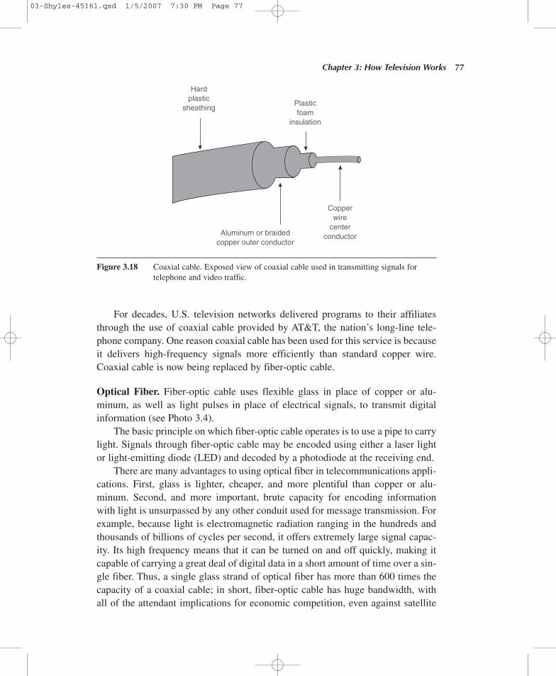
For decades, U.S. television networks delivered programs to their affiliatesthrough the use of coaxial cable provided by AT&T, the nation’s long-line tele-phone company. One reason coaxial cable has been used for this service is becauseit delivers high-frequency signals more efficiently than standard copper wire.Coaxial cable is now being replaced by fiber-optic cable.
Optical Fiber. Fiber-optic cable uses flexible glass in place of copper or alu-minum, as well as light pulses in place of electrical signals, to transmit digitalinformation (see Photo 3.4).
The basic principle on which fiber-optic cable operates is to use a pipe to carrylight. Signals through fiber-optic cable may be encoded using either a laser lightor light-emitting diode (LED) and decoded by a photodiode at the receiving end.
There are many advantages to using optical fiber in telecommunications appli-cations. First, glass is lighter, cheaper, and more plentiful than copper or alu-minum. Second, and more important, brute capacity for encoding informationwith light is unsurpassed by any other conduit used for message transmission. Forexample, because light is electromagnetic radiation ranging in the hundreds andthousands of billions of cycles per second, it offers extremely large signal capac-ity. Its high frequency means that it can be turned on and off quickly, making itcapable of carrying a great deal of digital data in a short amount of time over a sin-gle fiber. Thus, a single glass strand of optical fiber has more than 600 times thecapacity of a coaxial cable; in short, fiber-optic cable has huge bandwidth, with all of the attendant implications for economic competition, even against satellite
Chapter 3: How Television Works 77
Hardplastic
sheathingPlasticfoam
insulation
Aluminum or braidedcopper outer conductor
Copperwire
centerconductor
Figure 3.18 Coaxial cable. Exposed view of coaxial cable used in transmitting signals fortelephone and video traffic.
03-Shyles-45161.qxd 1/5/2007 7:30 PM Page 77
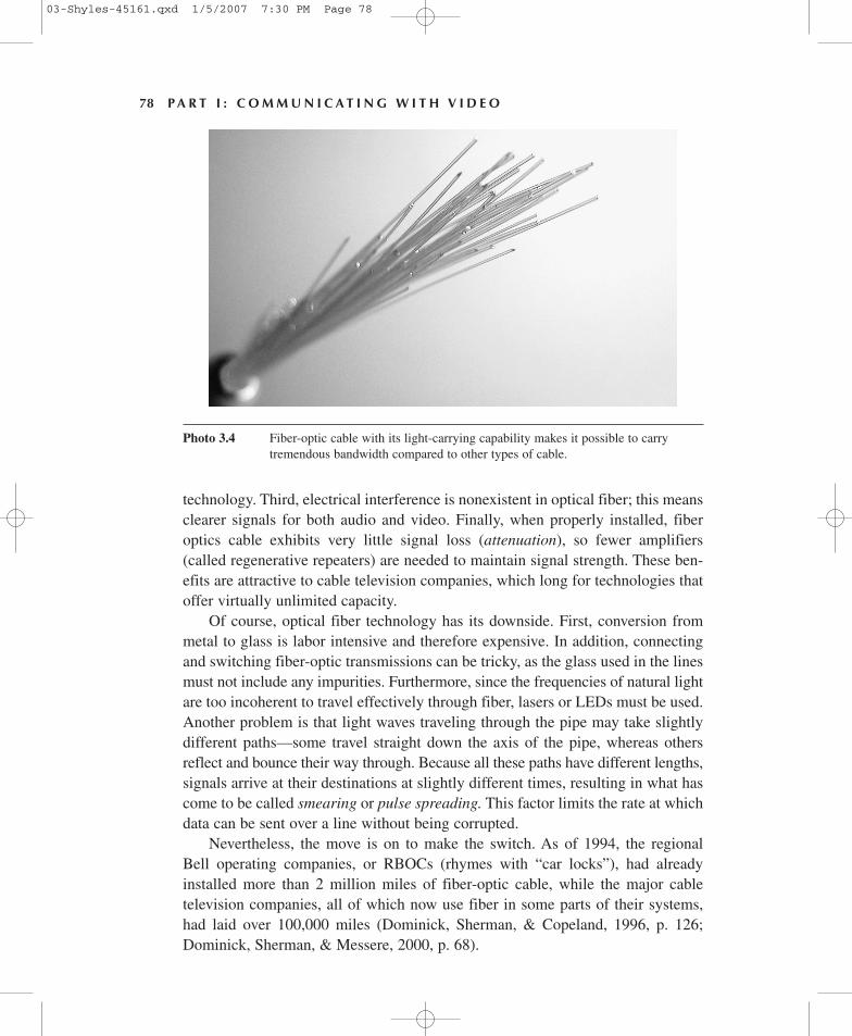
technology. Third, electrical interference is nonexistent in optical fiber; this meansclearer signals for both audio and video. Finally, when properly installed, fiberoptics cable exhibits very little signal loss (attenuation), so fewer amplifiers(called regenerative repeaters) are needed to maintain signal strength. These ben-efits are attractive to cable television companies, which long for technologies thatoffer virtually unlimited capacity.
Of course, optical fiber technology has its downside. First, conversion frommetal to glass is labor intensive and therefore expensive. In addition, connectingand switching fiber-optic transmissions can be tricky, as the glass used in the linesmust not include any impurities. Furthermore, since the frequencies of natural lightare too incoherent to travel effectively through fiber, lasers or LEDs must be used.Another problem is that light waves traveling through the pipe may take slightlydifferent paths—some travel straight down the axis of the pipe, whereas othersreflect and bounce their way through. Because all these paths have different lengths,signals arrive at their destinations at slightly different times, resulting in what hascome to be called smearing or pulse spreading. This factor limits the rate at whichdata can be sent over a line without being corrupted.
Nevertheless, the move is on to make the switch. As of 1994, the regionalBell operating companies, or RBOCs (rhymes with “car locks”), had alreadyinstalled more than 2 million miles of fiber-optic cable, while the major cabletelevision companies, all of which now use fiber in some parts of their systems,had laid over 100,000 miles (Dominick, Sherman, & Copeland, 1996, p. 126;Dominick, Sherman, & Messere, 2000, p. 68).
78 P A R T I : C O M M U N I C A T I N G W I T H V I D E O
Photo 3.4 Fiber-optic cable with its light-carrying capability makes it possible to carrytremendous bandwidth compared to other types of cable.
03-Shyles-45161.qxd 1/5/2007 7:30 PM Page 78
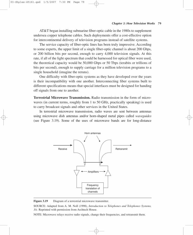
AT&T began installing submarine fiber-optic cable in the 1980s to supplementundersea copper telephone cables. Such deployments offer a cost-effective optionfor intercontinental delivery of television programs instead of satellite systems.
The service capacity of fiber-optic lines has been truly impressive. Accordingto some experts, the upper limit of a single fiber-optic channel is about 200 Gbps,or 200 billion bits per second, enough to carry 4,000 television signals. At thisrate, if all of the light spectrum that could be harnessed for optical fiber were used,the theoretical capacity would be 50,000 Gbps or 50 Tbps (terabits or trillions ofbits per second), enough to supply carriage for a million television programs to asingle household (imagine the reruns).
One difficulty with fiber-optic systems as they have developed over the yearsis their incompatibility with one another. Interconnecting fiber systems built todifferent specifications means that special interfaces must be designed for handingoff signals from one to another.
Terrestrial Microwave Transmission. Radio transmission in the form of micro-waves (in current terms, roughly from 1 to 50 GHz, practically speaking) is usedto carry broadcast signals and other services in the United States.
In terrestrial microwave transmission, radio waves are sent between antennasusing microwave dish antennas and/or horn-shaped metal pipes called waveguides (see Figure 3.19). Some of the uses of microwave bands are for long-distance
Chapter 3: How Television Works 79
Horn antennas
Frequencytranslation of
channels
Amplifiers
Receive Retransmit
Figure 3.19 Diagram of a terrestrial microwave transmitter.
SOURCE: Adapted from A. M. Noll (1998), Introduction to Telephones and Telephones Systems,3/e. Reprinted with permission from Archtech House.
NOTE: Microwave relays receive radio signals, change their frequencies, and retransmit them.
03-Shyles-45161.qxd 1/5/2007 7:30 PM Page 79
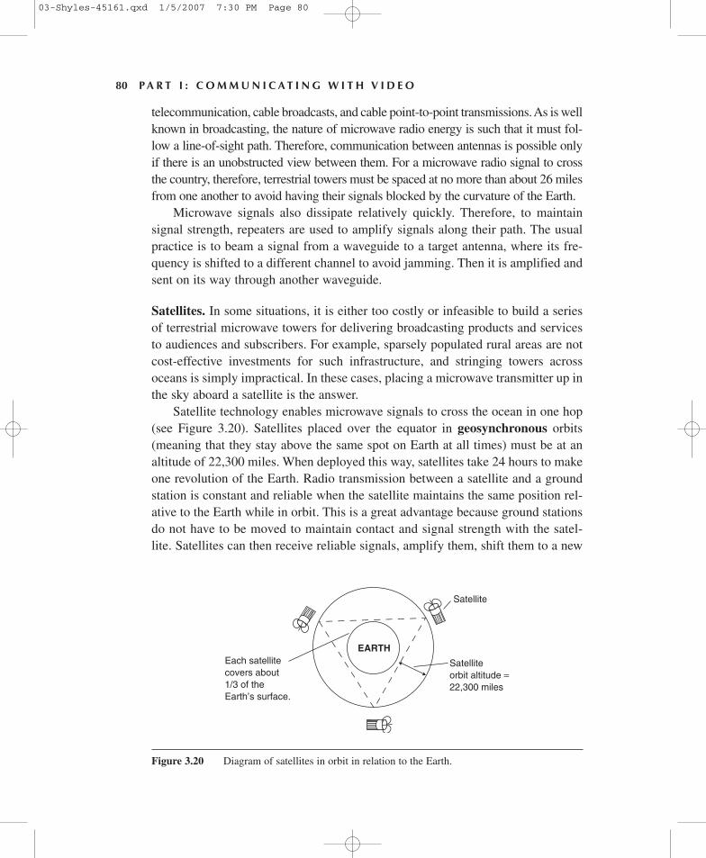
telecommunication, cable broadcasts, and cable point-to-point transmissions. As is wellknown in broadcasting, the nature of microwave radio energy is such that it must fol-low a line-of-sight path. Therefore, communication between antennas is possible onlyif there is an unobstructed view between them. For a microwave radio signal to crossthe country, therefore, terrestrial towers must be spaced at no more than about 26 milesfrom one another to avoid having their signals blocked by the curvature of the Earth.
Microwave signals also dissipate relatively quickly. Therefore, to maintainsignal strength, repeaters are used to amplify signals along their path. The usualpractice is to beam a signal from a waveguide to a target antenna, where its fre-quency is shifted to a different channel to avoid jamming. Then it is amplified andsent on its way through another waveguide.
Satellites. In some situations, it is either too costly or infeasible to build a seriesof terrestrial microwave towers for delivering broadcasting products and servicesto audiences and subscribers. For example, sparsely populated rural areas are notcost-effective investments for such infrastructure, and stringing towers acrossoceans is simply impractical. In these cases, placing a microwave transmitter up inthe sky aboard a satellite is the answer.
Satellite technology enables microwave signals to cross the ocean in one hop(see Figure 3.20). Satellites placed over the equator in geosynchronous orbits(meaning that they stay above the same spot on Earth at all times) must be at analtitude of 22,300 miles. When deployed this way, satellites take 24 hours to makeone revolution of the Earth. Radio transmission between a satellite and a groundstation is constant and reliable when the satellite maintains the same position rel-ative to the Earth while in orbit. This is a great advantage because ground stationsdo not have to be moved to maintain contact and signal strength with the satel-lite. Satellites can then receive reliable signals, amplify them, shift them to a new
80 P A R T I : C O M M U N I C A T I N G W I T H V I D E O
EARTH
Satellite
Satelliteorbit altitude =22,300 miles
Each satellitecovers about1/3 of theEarth’s surface.
Figure 3.20 Diagram of satellites in orbit in relation to the Earth.
03-Shyles-45161.qxd 1/5/2007 7:30 PM Page 80
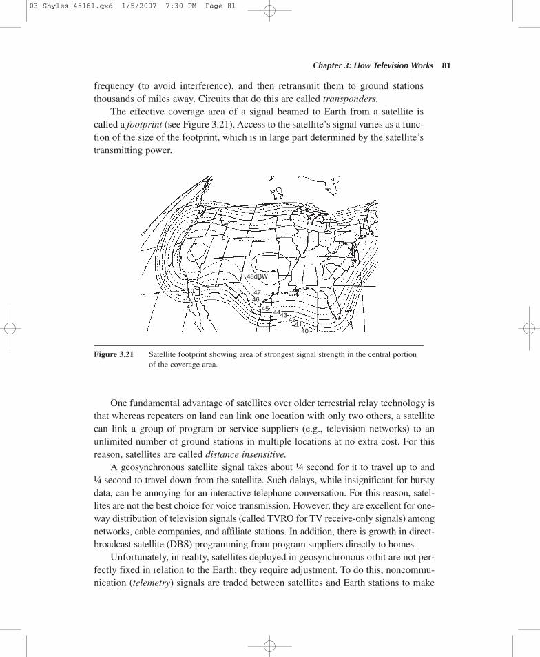
frequency (to avoid interference), and then retransmit them to ground stationsthousands of miles away. Circuits that do this are called transponders.
The effective coverage area of a signal beamed to Earth from a satellite iscalled a footprint (see Figure 3.21). Access to the satellite’s signal varies as a func-tion of the size of the footprint, which is in large part determined by the satellite’stransmitting power.
Chapter 3: How Television Works 81
48dBW
4746
45 444342
4140
Figure 3.21 Satellite footprint showing area of strongest signal strength in the central portionof the coverage area.
One fundamental advantage of satellites over older terrestrial relay technology isthat whereas repeaters on land can link one location with only two others, a satellitecan link a group of program or service suppliers (e.g., television networks) to anunlimited number of ground stations in multiple locations at no extra cost. For thisreason, satellites are called distance insensitive.
A geosynchronous satellite signal takes about ¼ second for it to travel up to and¼ second to travel down from the satellite. Such delays, while insignificant for burstydata, can be annoying for an interactive telephone conversation. For this reason, satel-lites are not the best choice for voice transmission. However, they are excellent for one-way distribution of television signals (called TVRO for TV receive-only signals) amongnetworks, cable companies, and affiliate stations. In addition, there is growth in direct-broadcast satellite (DBS) programming from program suppliers directly to homes.
Unfortunately, in reality, satellites deployed in geosynchronous orbit are not per-fectly fixed in relation to the Earth; they require adjustment. To do this, noncommu-nication (telemetry) signals are traded between satellites and Earth stations to make
03-Shyles-45161.qxd 1/5/2007 7:30 PM Page 81
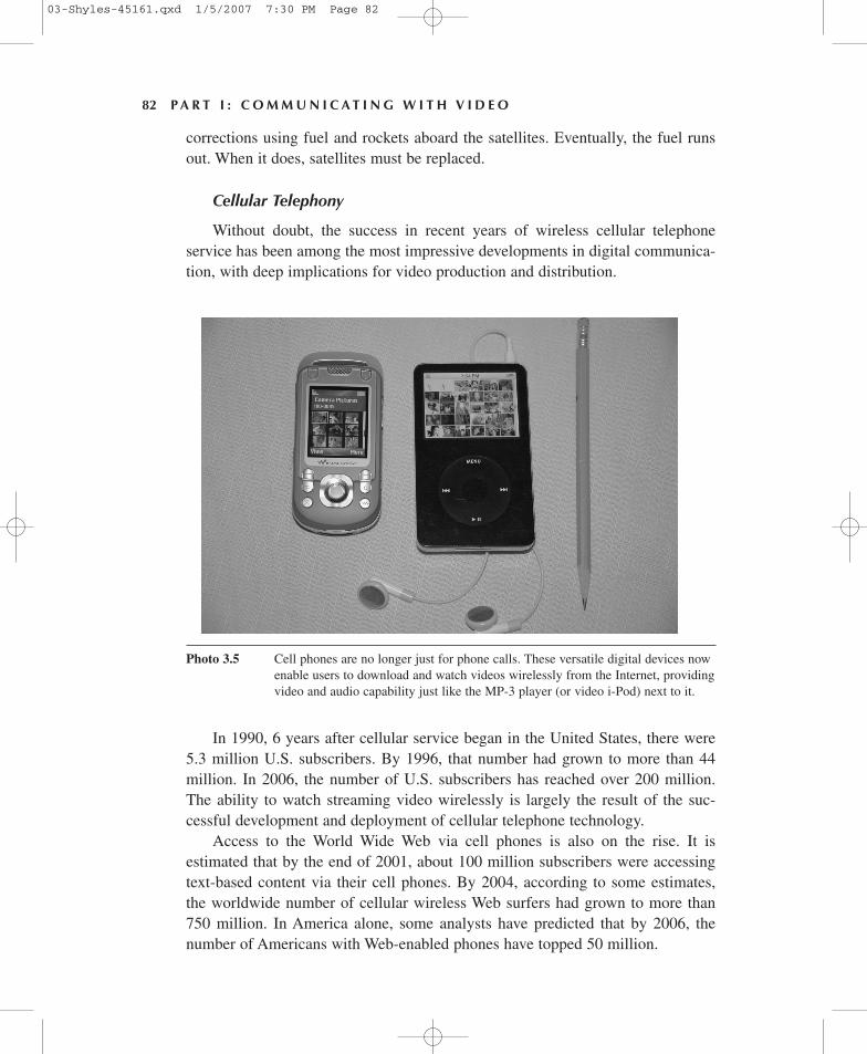
corrections using fuel and rockets aboard the satellites. Eventually, the fuel runsout. When it does, satellites must be replaced.
Cellular Telephony
Without doubt, the success in recent years of wireless cellular telephoneservice has been among the most impressive developments in digital communica-tion, with deep implications for video production and distribution.
82 P A R T I : C O M M U N I C A T I N G W I T H V I D E O
Photo 3.5 Cell phones are no longer just for phone calls. These versatile digital devices nowenable users to download and watch videos wirelessly from the Internet, providingvideo and audio capability just like the MP-3 player (or video i-Pod) next to it.
In 1990, 6 years after cellular service began in the United States, there were5.3 million U.S. subscribers. By 1996, that number had grown to more than 44million. In 2006, the number of U.S. subscribers has reached over 200 million.The ability to watch streaming video wirelessly is largely the result of the suc-cessful development and deployment of cellular telephone technology.
Access to the World Wide Web via cell phones is also on the rise. It isestimated that by the end of 2001, about 100 million subscribers were accessingtext-based content via their cell phones. By 2004, according to some estimates,the worldwide number of cellular wireless Web surfers had grown to more than750 million. In America alone, some analysts have predicted that by 2006, thenumber of Americans with Web-enabled phones have topped 50 million.
03-Shyles-45161.qxd 1/5/2007 7:30 PM Page 82
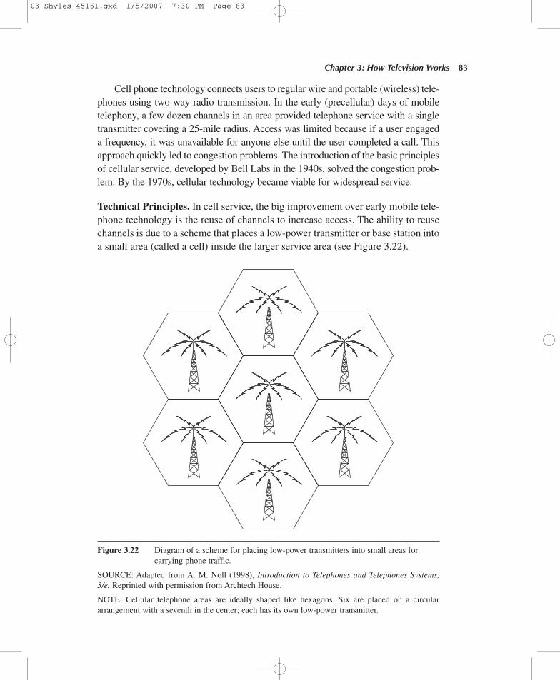
Cell phone technology connects users to regular wire and portable (wireless) tele-phones using two-way radio transmission. In the early (precellular) days of mobiletelephony, a few dozen channels in an area provided telephone service with a singletransmitter covering a 25-mile radius. Access was limited because if a user engageda frequency, it was unavailable for anyone else until the user completed a call. Thisapproach quickly led to congestion problems. The introduction of the basic principlesof cellular service, developed by Bell Labs in the 1940s, solved the congestion prob-lem. By the 1970s, cellular technology became viable for widespread service.
Technical Principles. In cell service, the big improvement over early mobile tele-phone technology is the reuse of channels to increase access. The ability to reusechannels is due to a scheme that places a low-power transmitter or base station intoa small area (called a cell) inside the larger service area (see Figure 3.22).
Chapter 3: How Television Works 83
Figure 3.22 Diagram of a scheme for placing low-power transmitters into small areas forcarrying phone traffic.
SOURCE: Adapted from A. M. Noll (1998), Introduction to Telephones and Telephones Systems,3/e. Reprinted with permission from Archtech House.
NOTE: Cellular telephone areas are ideally shaped like hexagons. Six are placed on a circulararrangement with a seventh in the center; each has its own low-power transmitter.
03-Shyles-45161.qxd 1/5/2007 7:30 PM Page 83
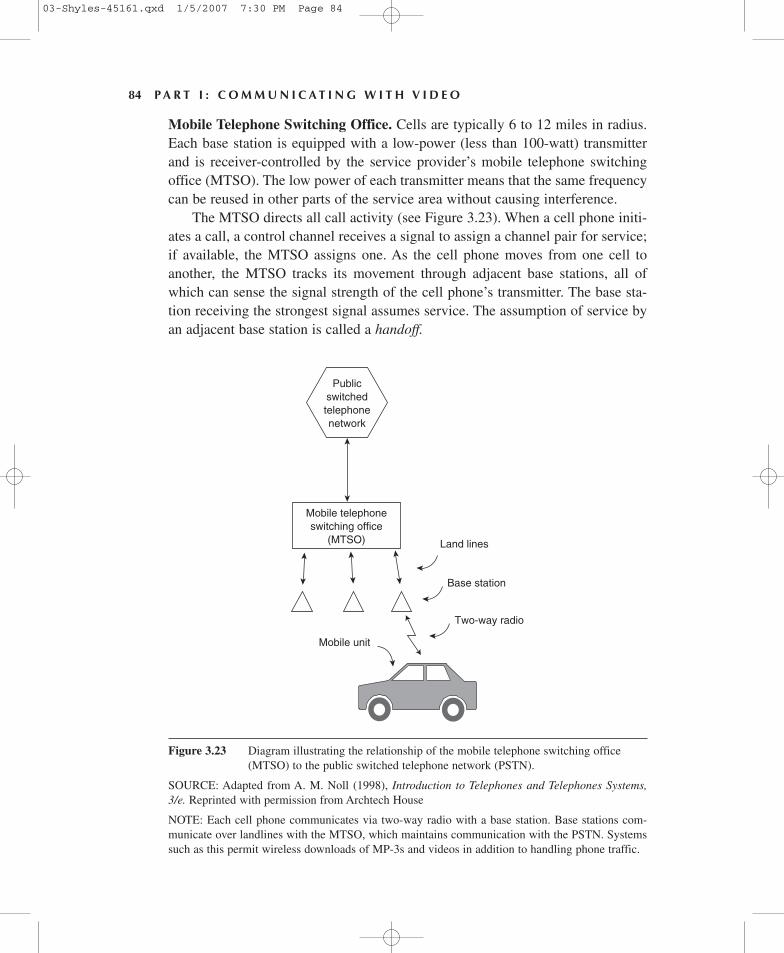
Mobile Telephone Switching Office. Cells are typically 6 to 12 miles in radius.Each base station is equipped with a low-power (less than 100-watt) transmitterand is receiver-controlled by the service provider’s mobile telephone switchingoffice (MTSO). The low power of each transmitter means that the same frequencycan be reused in other parts of the service area without causing interference.
The MTSO directs all call activity (see Figure 3.23). When a cell phone initi-ates a call, a control channel receives a signal to assign a channel pair for service;if available, the MTSO assigns one. As the cell phone moves from one cell toanother, the MTSO tracks its movement through adjacent base stations, all ofwhich can sense the signal strength of the cell phone’s transmitter. The base sta-tion receiving the strongest signal assumes service. The assumption of service byan adjacent base station is called a handoff.
84 P A R T I : C O M M U N I C A T I N G W I T H V I D E O
Mobile unit
Mobile telephoneswitching office
(MTSO)
Publicswitchedtelephonenetwork
Land lines
Base station
Two-way radio
Figure 3.23 Diagram illustrating the relationship of the mobile telephone switching office(MTSO) to the public switched telephone network (PSTN).
SOURCE: Adapted from A. M. Noll (1998), Introduction to Telephones and Telephones Systems,3/e. Reprinted with permission from Archtech House
NOTE: Each cell phone communicates via two-way radio with a base station. Base stations com-municate over landlines with the MTSO, which maintains communication with the PSTN. Systemssuch as this permit wireless downloads of MP-3s and videos in addition to handling phone traffic.
03-Shyles-45161.qxd 1/5/2007 7:30 PM Page 84
To have a full understanding of how technology enables us to create, store,transmit, receive, consume, and manipulate television and other content throughboth wire and wireless means, it is essential to know something about broadcast-ing, computers, and distribution networks. All three infrastructures are critical tocommerce in both mass media products and services; without all three, digitalvideo would not be what it is today.
K E Y T E R M S
Chapter 3: How Television Works 85
frequency 35
period 35
amplitude 35
wavelength 35
phase 35
electromagnetic waves 36
high fidelity 37
transducer 37
amplitude modulation (AM) 40
frequency modulation (FM) 40
demodulation 41
resolution 42
photoconductivity 44
photoemissive effect 44
pickup tube 45
charge-coupled device(CCD) 45
camera control unit (CCU) 45
viewfinder 45
pixels 46
persistence of vision 48
field 48
frame 48
aspect ratio 49
chrominance 49
luminance 49
saturation 49
digital television (DTV) 52
high-definition television(HDTV or HD) 52
progressive scanning 54
letterboxing 56
sampling 57
quantizing 57
broadband 57
narrowband 57
binary code 58
artificial intelligence (AI) 66
semiconductors 66
bandwidth 69
packet switching 72
throughput 74
lossy compression 75
lossless compression 75
geosynchronous 80
03-Shyles-45161.qxd 1/5/2007 7:30 PM Page 85
Q U E S T I O N S F O R R E V I E W
How does signal modulation make communication at a distance possible?
Describe the process of transduction in a microphone.
How do AM and FM differ? Why are FM signals less susceptible than AM to staticand interference?
Why did video engineers choose a scanning method for video signal transmission?
What components of the video signal must be sent to reproduce a coherent programat the receiver?
What are some production implications of current television technology?
What are some differences between the NTSC standard and the new DTV standard?
Describe several implications that result from integrating television technology withcomputers and telecommunications networks.
N O T E S
1. With digital television (DTV) systems, three scanning standards have emerged, including bothinterlaced and progressive formats, described in more detail later.
2. Actual picture resolution and frame rates of a received video image may differ from the res-olution and frame rate of the sent signal, depending on the user’s needs. For example, a DTV receivermay receive an interlaced image at one level of resolution but display it differently; that is, it mayplay a program back at 24-p (24 frames per second, progressively scanned), even though the programmay have originally been sent at 60-i (60 frames per second, interlaced scanned), performing suchfeats through the use of digital signal processors. Both the 480- and 1,080-line formats offer inter-laced or progressive scanning.
3. Silicon-based chips for computers are the semiconductor industry standard, but industryresearchers are planning for a transition away from conventional silicon transistors to nanotechnol-ogy using organic molecules and carbon-based materials as a way to increase computing powerbeyond what is believed possible with silicon. The transition to nanotechnology is now scheduled for2015 (see Markoff, 2005d).
4. A thorough review of the history of computers and binary code is beyond the scope of thisbook. Interested readers wanting more information about these topics should read “Computers inCommunication” in Shyles (2003, pp. 45–93). Excellent additional sources abound in print and onthe Internet. In print, see Augarten (1984) and Petzold. On-line sources include http://goldenink.com/computersandnetworks.shtml (retrieved December 26, 2005) and http://inventors.about.com/library/blcoindex.htm (retrieved December 26, 2005). Individuals who deserve further study includeBlaise Pascal, Gottfried Leibnitz, Joseph-Marie Jacquard, Charles Babbage, George Boole, ClaudeShannon, John Vincent Atanosoff, George Stibitz, Alan Turing, John Mauchly, J. Presper Eckert,John von Neumann, Jack Kilby, and John Noyce. While this list is not exhaustive, it is a great start.
5. At this writing, the Motion Picture Experts Group has MPEG versions up to MPEG-7, but itappears that the MPEG-2 standard is still among the leaders.
86 P A R T I : C O M M U N I C A T I N G W I T H V I D E O
03-Shyles-45161.qxd 1/5/2007 7:30 PM Page 86
PPAARRTT IIII
EELLEEMMEENNTTSS AANNDD TTEECCHHNNIIQQUUEESS
OOFF VVIIDDEEOO PPRROODDUUCCTTIIOONN
04-Shyles-45161.qxd 1/5/2007 7:06 PM Page 87