Embed Size (px)
Citation preview
724 CHAPTE R 27 CI RCU ITS
HALLIDAY REVISED
Additional examples, video, and practice available at WileyPLUS
their bottoms via the pavement. Figure 27-17b shows how thefour resistors are connected in parallel across the car’s capaci-tance, and Fig. 27-17c shows their equivalent resistance R.From Eq.27-24,R is given by
or (27-44)
When the car stops, it discharges its excess charge and en-ergy through R.
We now use our two Key Ideas to analyze the discharge.Substituting Eq. 27-39 into Eq. 25-21 gives
(27-45)
From Eq. 25-1 (q CV ), we can relate the initial charge q0
on the car to the given initial potential difference V0: q0 CV0. Substituting this equation into Eq. 27-45 brings us to
or (27-46)e2t/RC 2U
CV 02 .
U (CV0)2
2C e2t/RC
CV 02
2 e2t/RC,
q0
2
2C e2t/RC.
U q2
2C
(q0et/RC)2
2C
R Rtire
4
100 10 9
4 25 10 9 .
1R
1
Rtire
1Rtire
1
Rtire
1Rtire
,
Taking the natural logarithms of both sides, we obtain
or (27-47)
Substituting the given data, we find that the time the cartakes to discharge to the energy level Ufire 50 mJ is
(Answer)
Fire or no fire: This car requires at least 9.4 s before fuel ora fuel dispenser can be brought safely near it. During a race,a pit crew cannot wait that long. Instead, tires for race cars include some type of conducting material (such as carbonblack) to lower the tire resistance and thus increase the car’sdischarge rate. Figure 27-17d shows the stored energy U ver-sus time t for tire resistances of R 100 G (the value weused in our calculations here) and R 10 G. Note howmuch more rapidly a car discharges to level Ufire with thelower R value.
9.4 s.
ln 2(50 10 3 J)(500 10 12 F)(30 10 3 V)2
t (25 10 9 )(500 10 12 F)
2
t RC2
ln 2UCV0
2 .
2t
RC ln 2U
CV02 ,
Emf An emf device does work on charges to maintain a potentialdifference between its output terminals. If dW is the work the devicedoes to force positive charge dq from the negative to the positive ter-minal, then the emf (work per unit charge) of the device is
(definition of ). (27-1)
The volt is the SI unit of emf as well as of potential difference. Anideal emf device is one that lacks any internal resistance. The po-tential difference between its terminals is equal to the emf. A realemf device has internal resistance. The potential difference be-tween its terminals is equal to the emf only if there is no currentthrough the device.
Analyzing Circuits The change in potential in traversing a re-sistance R in the direction of the current is iR; in the opposite di-rection it is iR (resistance rule). The change in potential in tra-versing an ideal emf device in the direction of the emf arrow is ;in the opposite direction it is (emf rule). Conservation of en-ergy leads to the loop rule:
dWdq
Loop Rule. The algebraic sum of the changes in potential encounteredin a complete traversal of any loop of a circuit must be zero.
Conservation of charge gives us the junction rule:
Junction Rule. The sum of the currents entering any junctionmust be equal to the sum of the currents leaving that junction.
Single-Loop Circuits The current in a single-loop circuit con-taining a single resistance R and an emf device with emf and in-ternal resistance r is
(27-4)
which reduces to i /R for an ideal emf device with r 0.
Power When a real battery of emf and internal resistance rdoes work on the charge carriers in a current i through the battery,the rate P of energy transfer to the charge carriers is
P iV, (27-14)
where V is the potential across the terminals of the battery. The rate
i
R r,
halliday_c27_705-734v2.qxd 23-11-2009 14:35 Page 724
725QU E STION SPART 3
HALLIDAY REVISED
Pr at which energy is dissipated as thermal energy in the battery is
Pr i2r. (27-16)
The rate Pemf at which the chemical energy in the battery changes is
Pemf i. (27-17)
Series Resistances When resistances are in series, they havethe same current. The equivalent resistance that can replace a se-ries combination of resistances is
(n resistances in series). (27-7)
Parallel Resistances When resistances are in parallel,they have the same potential difference. The equivalent resistancethat can replace a parallel combination of resistances is given by
(n resistances in parallel). (27-24)1
Req
n
j1
1Rj
Req n
j1 Rj
RC Circuits When an emf is applied to a resistance R and ca-pacitance C in series, as in Fig. 27-15 with the switch at a, the chargeon the capacitor increases according to
q C (1 et/RC) (charging a capacitor), (27-33)
in which C q0 is the equilibrium (final) charge and RC t isthe capacitive time constant of the circuit. During the charging, thecurrent is
(charging a capacitor). (27-34)
When a capacitor discharges through a resistance R, the charge onthe capacitor decays according to
q q0et/RC (discharging a capacitor). (27-39)
During the discharging, the current is
(discharging a capacitor). (27-40) i dqdt
q0
RC et/RC
i dqdt
R et/RC
1 (a) In Fig. 27-18a, with R1 R2, is the potential differenceacross R2 more than, less than, or equal to that across R1? (b) Is thecurrent through resistor R2 more than, less than, or equal to thatthrough resistor R1?
Fig. 27-18 Questions 1 and 2.
(a)
+–
R1 R2
R3
(b)
+–
R3
R1R2
(d)(c)
R2R1+–
R3
R3
+–
R1
R2
R
Fig. 27-21 Question 6.
2 (a) In Fig. 27-18a, are resistors R1 and R3 in series? (b) Are resistors R1 and R2 in parallel? (c) Rank the equivalent resistancesof the four circuits shown in Fig. 27-18, greatest first.
3 You are to connect resistors R1 and R2, with R1 R2, to a bat-tery, first individually, then in series, and then in parallel. Rankthose arrangements according to the amount of current throughthe battery, greatest first.
4 In Fig. 27-19, a circuit consists ofa battery and two uniform resistors,and the section lying along an x axisis divided into five segments ofequal lengths. (a) Assume that R1 R2 and rank the segments accordingto the magnitude of the averageelectric field in them, greatest first. (b) Now assume that R1 R2
and then again rank the segments. (c) What is the direction of theelectric field along the x axis?
5 For each circuit in Fig. 27-20, are the resistors connected in series, in parallel, or neither?
6 Res-monster maze. In Fig. 27-21, all the resistors have aresistance of 4.0 and all the (ideal) batteries have an emf of 4.0V. What is the current through resistor R? (If you can find theproper loop through this maze, you can answer the question with afew seconds of mental calculation.)
Fig. 27-19 Question 4.
+ –
R1 R2
a b c d e
x
+–
+– +–
(a) (b) (c)
Fig. 27-20 Question 5.
7 A resistor R1 is wired to a battery, then resistor R2 is added inseries. Are (a) the potential difference across R1 and (b) the cur-
halliday_c27_705-734v2.qxd 23-11-2009 14:35 Page 725
726 CHAPTE R 27 CI RCU ITS
HALLIDAY REVISED
•4 Figure 27-27 shows a circuit of four resistors that are con-nected to a larger circuit.The graph below the circuit shows the elec-tric potential V(x) as a function of position x along the lower branchof the circuit, through resistor 4; the potential VA is 12.0 V. The graph
Fig. 27-24 Question 11.
(1) (2) (3)
sec. 27-6 Potential Difference Between Two Points•1 In Fig. 27-25, the idealbatteries have emfs 1 12 V and 2 6.0 V. What are (a) the current, the dissi-pation rate in (b) resistor 1 (4.0 ) and (c)resistor 2 (8.0 ), and the energy transferrate in (d) battery 1 and (e) battery 2? Isenergy being supplied or absorbed by (f)battery 1 and (g) battery 2?
•2 In Fig. 27-26, the ideal batteries have emfs 1 150 V and 2 50 Vand the resistances are R1 3.0 and R2 2.0 . If the potential at P is100 V, what is it at Q?
•3 A car battery with a 12 Vemf and an internal resistance of 0.040 is being charged with a current of 50A. What are (a) the potential differ-ence V across the terminals, (b) therate Pr of energy dissipation inside the battery, and (c) the rate Pemf
of energy conversion to chemical form? When the battery is used tosupply 50 A to the starter motor, what are (d) V and (e) Pr?
ILW
WWWSSM
–+
– +
12
R1
R2
–+
–+
Q
P
R1
R2
1 2
Fig. 27-26 Problem 2.
Fig. 27-27 Problem 4.
VA
0
0
x
x
4
1 2 3
∆VB ∆VC
V
V (V
)
Tutoring problem available (at instructor’s discretion) in WileyPLUS and WebAssign
SSM Worked-out solution available in Student Solutions Manual
• – ••• Number of dots indicates level of problem difficulty
Additional information available in The Flying Circus of Physics and at flyingcircusofphysics.com
WWW Worked-out solution is at
ILW Interactive solution is at http://www.wiley.com/college/halliday
R2 more than, less than, or equal to R1? (d) Is the total currentthrough R1 and R2 together more than, less than, or equal to thecurrent through R1 previously?
10 After the switch in Fig. 27-15 isclosed on point a, there is current ithrough resistance R. Figure 27-23gives that current for four sets ofvalues of R and capacitance C: (1) R0
and C0, (2) 2R0 and C0, (3) R0 and2C0, (4) 2R0 and 2C0. Which set goeswith which curve?
11 Figure 27-24 shows three sec-tions of circuit that are to be con-nected in turn to the same batteryvia a switch as in Fig. 27-15.The resistors are all identical, as are thecapacitors. Rank the sections according to (a) the final (equilib-rium) charge on the capacitor and (b) the time required for thecapacitor to reach 50% of its final charge, greatest first.
rent i1 through R1 now more than, less than, or the same as previ-ously? (c) Is the equivalent resistance R12 of R1 and R2 more than,less than, or equal to R1?
8 Cap-monster maze. In Fig. 27-22, all the capacitors have acapacitance of 6.0 mF, and all the batteries have an emf of 10 V.What is the charge on capacitor C? (If you can find the proper loopthrough this maze, you can answer the question with a few secondsof mental calculation.)
9 Initially, a single resistor R1 is wired to a battery. Then resistorR2 is added in parallel. Are (a) the potential difference across R1
and (b) the current i1 through R1 now more than, less than, or thesame as previously? (c) Is the equivalent resistance R12 of R1 and
C
Fig. 27-22 Question 8.
i
dc
a
b
t
Fig. 27-23 Question 10.
Fig. 27-25Problem 1.
halliday_c27_705-734v2.qxd 23-11-2009 14:35 Page 726
••15 The current in a single-loop circuit with one resistanceR is 5.0 A. When an additional resistance of 2.0 is inserted in se-ries with R, the current drops to 4.0 A.What is R?
•••16 A solar cell generates a potential difference of 0.10 Vwhen a 500 resistor is connected across it, and a potential dif-ference of 0.15 V when a 1000 resistor is substituted. What arethe (a) internal resistance and (b) emf of the solar cell? (c) Thearea of the cell is 5.0 cm2, and the rate per unit area at which it re-ceives energy from light is 2.0 mW/cm2. What is the efficiency ofthe cell for converting light energy to thermal energy in the 1000 external resistor?
•••17 In Fig. 27-33, battery 1 has emf1 12.0 V and internal resistance r1 0.016 and battery 2 has emf 2 12.0 V and in-ternal resistance r2 0.012 . The batteriesare connected in series with an external resis-tance R. (a) What R value makes the termi-nal-to-terminal potential difference of one ofthe batteries zero? (b) Which battery is that?
sec. 27-7 Multiloop Circuits•18 In Fig. 27-9, what is the potential difference Vd Vc betweenpoints d and c if 1 4.0 V, 2 1.0 V, R1 R2 10 , and R3 5.0, and the battery is ideal?
•19 A total resistance of 3.00 is to be produced by connectingan unknown resistance to a 12.0 resistance. (a) What must be thevalue of the unknown resistance, and (b) should it be connected inseries or in parallel?
•20 When resistors 1 and 2 are connected in series, the equivalentresistance is 16.0 . When they are connected in parallel, theequivalent resistance is 3.0 . What are (a) the smaller resistance
SSM
ILW
above the circuit shows the electric potential V(x) versus position xalong the upper branch of the circuit, through resistors 1, 2, and 3;the potential differences are VB 2.00 V and VC 5.00 V.Resistor 3 has a resistance of 200 . What is the resistance of (a) re-sistor 1 and (b) resistor 2?
•5 A 5.0 A current is set up in a circuit for 6.0 min by a recharge-able battery with a 6.0 V emf. By how much is the chemical energyof the battery reduced?
•6 A standard flashlight battery can deliver about 2.0 W h of en-ergy before it runs down. (a) If a battery costs US$0.80, what is thecost of operating a 100 W lamp for 8.0 h using batteries? (b) Whatis the cost if energy is provided at the rate of US$0.06 per kilowatt-hour?
•7 A wire of resistance 5.0 is connected to a battery whose emf is 2.0 V and whose internal resistance is 1.0 . In 2.0 min, howmuch energy is (a) transferred from chemical form in the battery,(b) dissipated as thermal energy in the wire, and (c) dissipated asthermal energy in the battery?
•8 A certain car battery with a 12.0 V emf has an initial charge of120 A h. Assuming that the potential across the terminals stays con-stant until the battery is completely discharged, for how many hourscan it deliver energy at the rate of 100 W?
•9 (a) In electron-volts, how much work does an ideal batterywith a 12.0 V emf do on an electron that passes through the batteryfrom the positive to the negative terminal? (b) If 3.40 1018 elec-trons pass through each second, what is the power of the battery inwatts?
••10 (a) In Fig. 27-28, what valuemust R have if the current in the cir-cuit is to be 1.0 mA? Take 1 2.0V, 2 3.0 V, and r1 r2 3.0 .(b) What is the rate at which thermalenergy appears in R?
••11 In Fig. 27-29, circuitsection AB absorbs energy at a rateof 50 W when current i 1.0 Athrough it is in the indicated direc-tion. Resistance R 2.0 . (a) Whatis the potential difference betweenA and B? Emf device X lacks inter-nal resistance. (b) What is its emf?(c) Is point B connected to the posi-tive terminal of X or to the negative terminal?
••12 Figure 27-30 shows a resistor of resistance R 6.00 con-nected to an ideal battery of emf 12.0 V by means of two copperwires. Each wire has length 20.0 cm and radius1.00 mm.In dealing with such circuits in this chap-ter, we generally neglect the potential differencesalong the wires and the transfer of energy to ther-mal energy in them. Check the validity of this ne-glect for the circuit of Fig. 27-30: What is the po-tential difference across (a) the resistor and (b)each of the two sections of wire? At what rate isenergy lost to thermal energy in (c) the resistorand (d) each section of wire?
••13 A 10-km-long underground cable extends east to west andconsists of two parallel wires, each of which has resistance 13
SSM
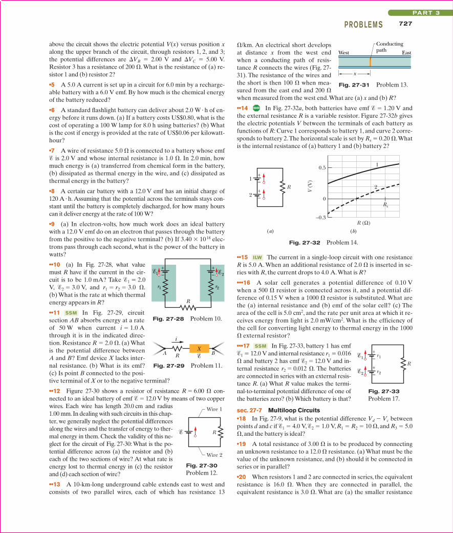
/km. An electrical short developsat distance x from the west endwhen a conducting path of resis-tance R connects the wires (Fig. 27-31). The resistance of the wires andthe short is then 100 when mea-sured from the east end and 200 when measured from the west end.What are (a) x and (b) R?
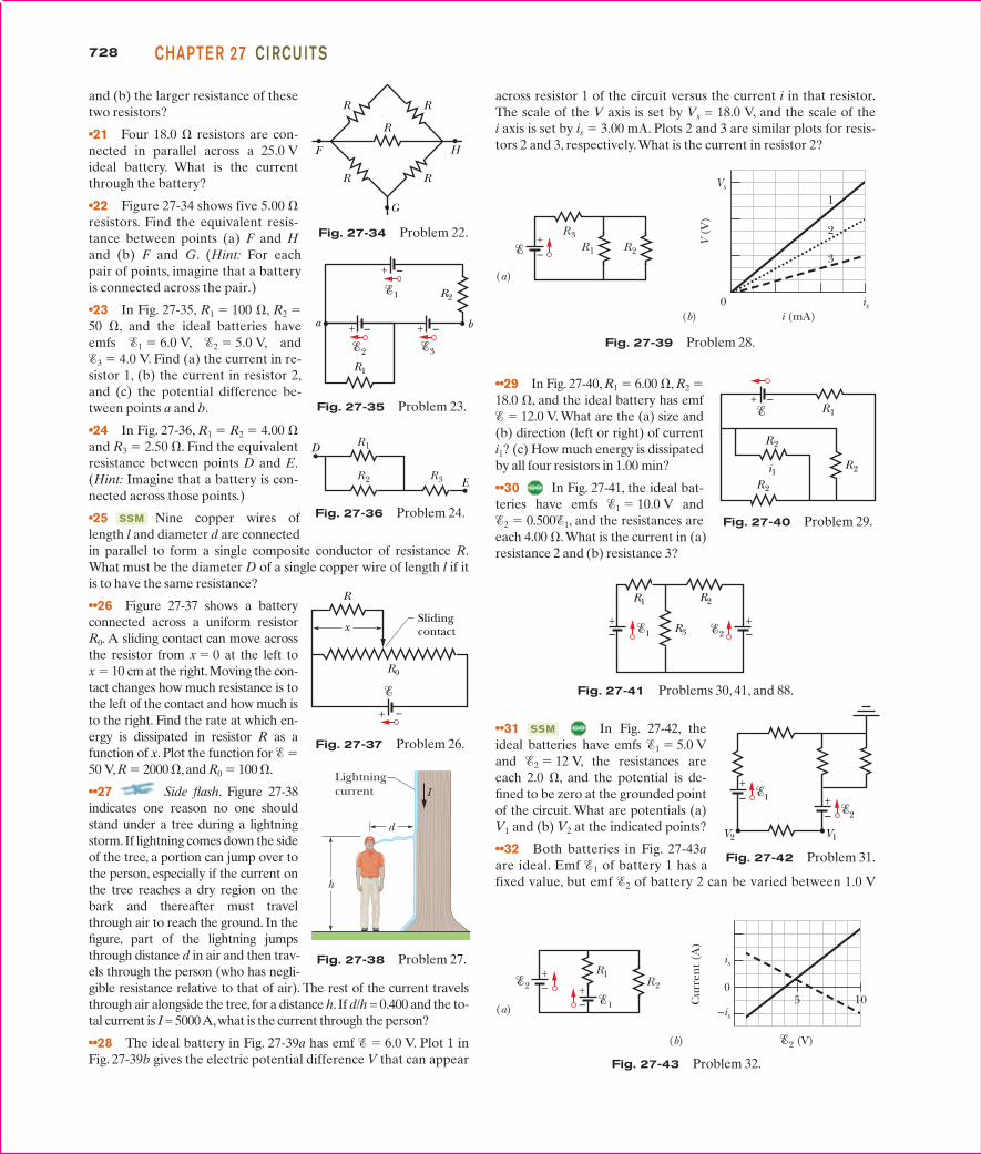
••14 In Fig. 27-32a, both batteries have emf 1.20 V andthe external resistance R is a variable resistor. Figure 27-32b givesthe electric potentials V between the terminals of each battery asfunctions of R: Curve 1 corresponds to battery 1, and curve 2 corre-sponds to battery 2.The horizontal scale is set by Rs 0.20 .Whatis the internal resistance of (a) battery 1 and (b) battery 2?
X
i
A BR
Fig. 27-29 Problem 11.
Wire 1
Wire 2
R
Fig. 27-30Problem 12.
West East
Conductingpath
x
Fig. 27-31 Problem 13.
R
1
2
1
2
Rs
R (Ω)
0.5
0
–0.3
V (V
)
(a) (b)
–+
–+
Fig. 27-32 Problem 14.
R
r1
r2
–+
–+
1
2
Fig. 27-33Problem 17.
–+
r1
1 –+
r2
2
R
Fig. 27-28 Problem 10.
727PROB LE M SPART 3
HALLIDAY REVISED
halliday_c27_705-734v2.qxd 23-11-2009 14:35 Page 727
••31 In Fig. 27-42, theideal batteries have emfs 1 5.0 Vand 2 12 V, the resistances areeach 2.0 , and the potential is de-fined to be zero at the grounded pointof the circuit. What are potentials (a)V1 and (b) V2 at the indicated points?
••32 Both batteries in Fig. 27-43aare ideal. Emf 1 of battery 1 has afixed value, but emf 2 of battery 2 can be varied between 1.0 V
SSM
••29 In Fig. 27-40, R1 6.00 , R2 18.0 , and the ideal battery has emf 12.0 V. What are the (a) size and(b) direction (left or right) of currenti1? (c) How much energy is dissipatedby all four resistors in 1.00 min?
••30 In Fig. 27-41, the ideal bat-teries have emfs 1 10.0 V and2 0.5001, and the resistances areeach 4.00 .What is the current in (a)resistance 2 and (b) resistance 3?
728 CHAPTE R 27 CI RCU ITS
HALLIDAY REVISED
and (b) the larger resistance of thesetwo resistors?
•21 Four 18.0 resistors are con-nected in parallel across a 25.0 Videal battery. What is the currentthrough the battery?
•22 Figure 27-34 shows five 5.00 resistors. Find the equivalent resis-tance between points (a) F and Hand (b) F and G. (Hint: For eachpair of points, imagine that a batteryis connected across the pair.)
•23 In Fig. 27-35, R1 100 , R2 50 , and the ideal batteries haveemfs 1 6.0 V, 2 5.0 V, and 3 4.0 V. Find (a) the current in re-sistor 1, (b) the current in resistor 2,and (c) the potential difference be-tween points a and b.
•24 In Fig. 27-36, R1 R2 4.00 and R3 2.50 . Find the equivalentresistance between points D and E.(Hint: Imagine that a battery is con-nected across those points.)
•25 Nine copper wires oflength l and diameter d are connectedin parallel to form a single composite conductor of resistance R.What must be the diameter D of a single copper wire of length l if itis to have the same resistance?
••26 Figure 27-37 shows a batteryconnected across a uniform resistorR0. A sliding contact can move acrossthe resistor from x 0 at the left to x 10 cm at the right.Moving the con-tact changes how much resistance is tothe left of the contact and how much isto the right. Find the rate at which en-ergy is dissipated in resistor R as afunction of x. Plot the function for 50 V,R 2000 ,and R0 100 .
••27 Side flash. Figure 27-38indicates one reason no one shouldstand under a tree during a lightningstorm.If lightning comes down the sideof the tree, a portion can jump over tothe person, especially if the current onthe tree reaches a dry region on thebark and thereafter must travelthrough air to reach the ground. In thefigure, part of the lightning jumpsthrough distance d in air and then trav-els through the person (who has negli-gible resistance relative to that of air). The rest of the current travelsthrough air alongside the tree, for a distance h. If d/h = 0.400 and the to-tal current is I = 5000 A,what is the current through the person?
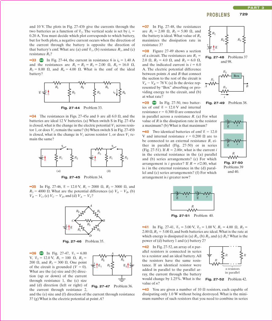
••28 The ideal battery in Fig. 27-39a has emf 6.0 V. Plot 1 inFig. 27-39b gives the electric potential difference V that can appear
SSM
across resistor 1 of the circuit versus the current i in that resistor.The scale of the V axis is set by Vs = 18.0 V, and the scale of the i axis is set by is 3.00 m. Plots 2 and 3 are similar plots for resis-tors 2 and 3, respectively.What is the current in resistor 2?
x
+ –
R
R0
Slidingcontact
Fig. 27-37 Problem 26.
V (V
)
Vs
0
1
i (mA)
2
is
3
(b)
R2R1
R3
(a)
+–
Fig. 27-39 Problem 28.
2 (V)
Cur
ren
t (A
)
is
0
–is5 10
(b)
2
1
R2
R1
(a)
+– +
–
Fig. 27-43 Problem 32.
G
HF
R R
R
R R
Fig. 27-34 Problem 22.
R2
+ –
1
R1
+ – + –
3 2
a b
Fig. 27-35 Problem 23.
R2 R3
D
E
R1
Fig. 27-36 Problem 24.
h
d
ILightningcurrent
Fig. 27-38 Problem 27.
i1
R1
R2
R2
R2
+ –
Fig. 27-40 Problem 29.
+–2R3
+– 1
R2R1
Fig. 27-41 Problems 30, 41, and 88.
V2 V1
1
+–
2
+–
Fig. 27-42 Problem 31.
halliday_c27_705-734v2.qxd 23-11-2009 14:35 Page 728
••41 In Fig. 27-41, 1 3.00 V, 2 1.00 V, R1 4.00 , R2 2.00 , R3 5.00 , and both batteries are ideal.What is the rate atwhich energy is dissipated in (a) R1, (b) R2, and (c) R3? What is thepower of (d) battery 1 and (e) battery 2?
••42 In Fig. 27-52, an array of n par-allel resistors is connected in seriesto a resistor and an ideal battery. Allthe resistors have the same resis-tance. If an identical resistor wereadded in parallel to the parallel ar-ray, the current through the batterywould change by 1.25%. What is thevalue of n?
••43 You are given a number of 10 resistors, each capable ofdissipating only 1.0 W without being destroyed. What is the mini-mum number of such resistors that you need to combine in series
••36 In Fig. 27-47, 1 6.00V, 2 12.0 V, R1 100 , R2 200 , and R3 300 . One pointof the circuit is grounded (V 0).What are the (a) size and (b) direc-tion (up or down) of the currentthrough resistance 1, the (c) sizeand (d) direction (left or right) ofthe current through resistance 2,and the (e) size and (f) direction of the current through resistance3? (g) What is the electric potential at point A?
and 10 V. The plots in Fig. 27-43b give the currents through thetwo batteries as a function of 2. The vertical scale is set by is 0.20 A. You must decide which plot corresponds to which battery,but for both plots, a negative current occurs when the direction ofthe current through the battery is opposite the direction ofthat battery’s emf. What are (a) emf 1, (b) resistance R1, and (c)resistance R2?
••33 In Fig. 27-44, the current in resistance 6 is i6 1.40 Aand the resistances are R1 R2 R3 2.00 , R4 16.0 ,R5 8.00 , and R6 4.00 . What is the emf of the idealbattery?
••37 In Fig. 27-48, the resistancesare R1 2.00 , R2 5.00 , andthe battery is ideal. What value of R3
maximizes the dissipation rate inresistance 3?
••38 Figure 27-49 shows a sectionof a circuit. The resistances are R1 2.0 , R2 4.0 , and R3 6.0 ,and the indicated current is i 6.0A. The electric potential differencebetween points A and B that connectthe section to the rest of the circuit isVA VB 78 V. (a) Is the device rep-resented by “Box” absorbing or pro-viding energy to the circuit, and (b)at what rate?
••39 In Fig. 27-50, two batter-ies of emf 12.0 V and internalresistance r 0.300 are connectedin parallel across a resistance R. (a) For whatvalue of R is the dissipation rate in the resistora maximum? (b) What is that maximum?
••40 Two identical batteries of emf 12.0V and internal resistance r 0.200 are tobe connected to an external resistance R, ei-ther in parallel (Fig. 27-50) or in series(Fig. 27-51). If R 2.00r, what is the current iin the external resistance in the (a) paralleland (b) series arrangements? (c) For whicharrangement is i greater? If R r/2.00, whatis i in the external resistance in the (d) paral-lel and (e) series arrangements? (f) For whicharrangement is i greater now?
(a) (b)
R2R1
S
R2R1
R3
S
+–
+–
Fig. 27-45 Problem 34.
R1
R1
R3
R2
R2
A
B
D
C+–
Fig. 27-46 Problem 35.
1 2R1
R2 R3
A
+–
+–
Fig. 27-47 Problem 36.
+–
R3R2
R1
Fig. 27-48 Problems 37and 98.
Box
A B
i
R1
R2
R3
Fig. 27-49 Problem 38.
+ –
+ –r
r
R
Fig. 27-50Problems 39
and 40.
+ – + –rr
R
Fig. 27-51 Problem 40.
RR
R
n resistorsin parallel
Fig. 27-52 Problem 42.
R2R1 R5
R4 R6R3 i6+–
Fig. 27-44 Problem 33.
729PROB LE M SPART 3
HALLIDAY REVISED
••34 The resistances in Figs. 27-45a and b are all 6.0 , and thebatteries are ideal 12 V batteries. (a) When switch S in Fig. 27-45ais closed, what is the change in the electric potential V1 across resis-tor 1, or does V1 remain the same? (b) When switch S in Fig. 27-45bis closed, what is the change in V1 across resistor 1, or does V1 re-main the same?
••35 In Fig. 27-46, 12.0 V, R1 2000 , R2 3000 , and R3 4000 . What are the potential differences (a) VA VB, (b)VB VC, (c) VC VD, and (d) VA VC?
halliday_c27_705-734v2.qxd 23-11-2009 14:35 Page 729
••53 In Fig. 27-14, assume that 3.0 V, r 100 , R1 250 ,and R2 300 . If the voltmeter resistance RV is 5.0 k, whatpercent error does it introduce into the measurement of the po-tential difference across R1? Ignorethe presence of the ammeter.
••54 When the lights of a car areswitched on, an ammeter in series withthem reads 10.0 A and a voltmeterconnected across them reads 12.0 V(Fig. 27-60). When the electric startingmotor is turned on, the ammeter read-ing drops to 8.00 A and the lights dimsomewhat. If the internal resistance ofthe battery is 0.0500 and that of theammeter is negligible, what are (a) theemf of the battery and (b) the currentthrough the starting motor when thelights are on?
•••47 A copper wire of radius a 0.250 mm has an aluminum jacket of outer radius b 0.380 mm. There is a current i 2.00 A in the composite wire. Using Table 26-1, calculate thecurrent in (a) the copper and (b) the aluminum. (c) If a potentialdifference V 12.0 V between the ends maintains the current,what is the length of the composite wire?
•••48 In Fig. 27-53, the resistors have the values R1 7.00 , R2 12.0 , and R3 4.00 , and the ideal battery’s emf is 24.0 V. Forwhat value of R4 will the rate at which the battery transfers energy tothe resistors equal (a) 60.0 W, (b) the maximum possible rate Pmax, and(c) the minimum possible rate Pmin? What are (d) Pmax and (e) Pmin?
sec. 27-8 The Ammeter and the Voltmeter••49 (a) In Fig. 27-56,what does the ammeter read if 5.0 V (ideal battery), R1 2.0 , R2 4.0 , and R3 6.0? (b) The ammeter and bat-tery are now interchanged.Show that the ammeter readingis unchanged.
ILW
SSM
730 CHAPTE R 27 CI RCU ITS
HALLIDAY REVISED
or in parallel to make a 10 resistance that is capable of dissipat-ing at least 5.0 W?
••44 In Fig. 27-53, R1 100 ,R2 R3 50.0 , R4 75.0 , andthe ideal battery has emf 6.00 V.(a) What is the equivalent resis-tance? What is i in (b) resistance 1,(c) resistance 2, (d) resistance 3, and(e) resistance 4?
••45 In Fig. 27-54, the resis-tances are R1 1.0 and R2 2.0, and the ideal batteries have emfs1 2.0 V and 2 3 4.0 V.What are the (a) size and (b) direc-tion (up or down) of the current inbattery 1, the (c) size and (d) direc-tion of the current in battery 2, andthe (e) size and (f) direction of thecurrent in battery 3? (g) What is thepotential difference Va Vb?
••46 In Fig. 27-55a, resistor 3 is avariable resistor and the ideal battery has emf 12 V. Figure27-55b gives the current i through the battery as a function of R3.The horizontal scale is set by R3s 20 . The curve has an as-ymptote of 2.0 mA as R3 : . What are (a) resistance R1 and (b)resistance R2?
ILW
••50 In Fig. 27-57, R1 2.00R, theammeter resistance is zero, and thebattery is ideal.What multiple of /Rgives the current in the ammeter?
••51 In Fig. 27-58, a voltmeter ofresistance RV 300 and an amme-ter of resistance RA 3.00 are be-ing used to measure a resistance R ina circuit that also contains a resis-tance R0 100 and an ideal bat-tery of emf 12.0 V. Resistance Ris given by R V/i, where V is thepotential across R and i is the amme-ter reading. The voltmeter reading isV, which is V plus the potential dif-ference across the ammeter. Thus,the ratio of the two meter readings isnot R but only an apparent resistanceR V/i. If R 85.0 , what are (a)the ammeter reading, (b) the voltmeter reading, and (c) R? (d) IfRA is decreased, does the difference between R and R increase,decrease, or remain the same?
••52 A simple ohmmeter is made by connecting a 1.50 V flash-light battery in series with a resistance R and an ammeter thatreads from 0 to 1.00 mA, as shown in Fig. 27-59. Resistance R isadjusted so that when the clip leads are shorted together, the me-ter deflects to its full-scale value of 1.00 mA. What external resis-tance across the leads results in a deflection of (a) 10.0%, (b)50.0%, and (c) 90.0% of full scale? (d) If the ammeter has a resis-tance of 20.0 and the internal resistance of the battery is negli-gible, what is the value of R?
+–
R3
A
R2
R1
Fig. 27-56 Problem 49.
+–
R
A
R
R
R1
Fig. 27-57 Problem 50.
+ –
R
R0
V
A
Fig. 27-58 Problem 51.
Fig. 27-59 Problem 52.
+–
0–1.00mA
R
V
+ –
S
SStartingmotor
Lights
A
r
Fig. 27-60Problem 54.
R3R2
R1
i (m
A)
6
4
2
0R3 (Ω)
R3s
(a) (b)
+–
Fig. 27-55 Problem 46.
+–3
R1+– 2
R2+– 1
R1R1
R1
a
b
Fig. 27-54Problem 45.
R2+–
R1
R3
R4
Fig. 27-53Problems 44 and 48.
halliday_c27_705-734v2.qxd 23-11-2009 14:35 Page 730
731PROB LE M SPART 3
HALLIDAY REVISED
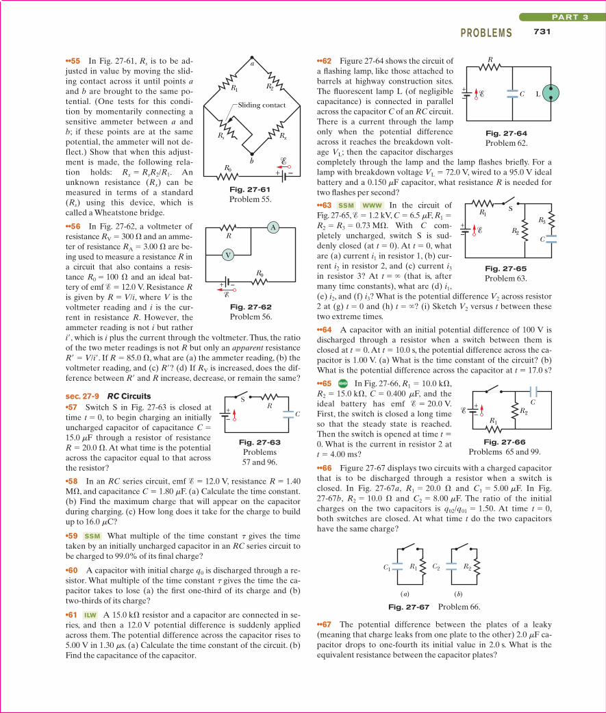
••55 In Fig. 27-61, Rs is to be ad-justed in value by moving the slid-ing contact across it until points aand b are brought to the same po-tential. (One tests for this condi-tion by momentarily connecting asensitive ammeter between a andb; if these points are at the samepotential, the ammeter will not de-flect.) Show that when this adjust-ment is made, the following rela-tion holds: Rx RsR2/R1. Anunknown resistance (Rx) can bemeasured in terms of a standard(Rs) using this device, which iscalled a Wheatstone bridge.
••56 In Fig. 27-62, a voltmeter ofresistance RV 300 and an amme-ter of resistance RA 3.00 are be-ing used to measure a resistance R ina circuit that also contains a resis-tance R0 100 and an ideal bat-tery of emf 12.0 V. Resistance Ris given by R V/i, where V is thevoltmeter reading and i is the cur-rent in resistance R. However, theammeter reading is not i but ratheri, which is i plus the current through the voltmeter. Thus, the ratioof the two meter readings is not R but only an apparent resistanceR V/i. If R 85.0 , what are (a) the ammeter reading, (b) thevoltmeter reading, and (c) R? (d) If RV is increased, does the dif-ference between R and R increase, decrease, or remain the same?
sec. 27-9 RC Circuits•57 Switch S in Fig. 27-63 is closed attime t 0, to begin charging an initiallyuncharged capacitor of capacitance C 15.0 mF through a resistor of resistance R 20.0 . At what time is the potentialacross the capacitor equal to that acrossthe resistor?
•58 In an RC series circuit, emf 12.0 V, resistance R 1.40M, and capacitance C 1.80 mF. (a) Calculate the time constant.(b) Find the maximum charge that will appear on the capacitorduring charging. (c) How long does it take for the charge to buildup to 16.0 mC?
•59 What multiple of the time constant t gives the timetaken by an initially uncharged capacitor in an RC series circuit tobe charged to 99.0% of its final charge?
•60 A capacitor with initial charge q0 is discharged through a re-sistor. What multiple of the time constant t gives the time the ca-pacitor takes to lose (a) the first one-third of its charge and (b)two-thirds of its charge?
•61 A 15.0 k resistor and a capacitor are connected in se-ries, and then a 12.0 V potential difference is suddenly appliedacross them. The potential difference across the capacitor rises to5.00 V in 1.30 ms. (a) Calculate the time constant of the circuit. (b)Find the capacitance of the capacitor.
ILW
SSM
••62 Figure 27-64 shows the circuit ofa flashing lamp, like those attached tobarrels at highway construction sites.The fluorescent lamp L (of negligiblecapacitance) is connected in parallelacross the capacitor C of an RC circuit.There is a current through the lamponly when the potential differenceacross it reaches the breakdown volt-age VL; then the capacitor dischargescompletely through the lamp and the lamp flashes briefly. For alamp with breakdown voltage VL 72.0 V, wired to a 95.0 V idealbattery and a 0.150 mF capacitor, what resistance R is needed fortwo flashes per second?
••63 In the circuit ofFig. 27-65, 1.2 kV, C 6.5 mF, R1 R2 R3 0.73 M. With C com-pletely uncharged, switch S is sud-denly closed (at t 0). At t 0, whatare (a) current i1 in resistor 1, (b) cur-rent i2 in resistor 2, and (c) current i3
in resistor 3? At t (that is, aftermany time constants), what are (d) i1,(e) i2, and (f) i3? What is the potential difference V2 across resistor2 at (g) t 0 and (h) t ? (i) Sketch V2 versus t between thesetwo extreme times.
••64 A capacitor with an initial potential difference of 100 V isdischarged through a resistor when a switch between them isclosed at t 0. At t 10.0 s, the potential difference across the ca-pacitor is 1.00 V. (a) What is the time constant of the circuit? (b)What is the potential difference across the capacitor at t 17.0 s?
••65 In Fig. 27-66, R1 10.0 k,R2 15.0 k, C 0.400 mF, and theideal battery has emf 20.0 V.First, the switch is closed a long timeso that the steady state is reached.Then the switch is opened at time t 0. What is the current in resistor 2 at t 4.00 ms?
••66 Figure 27-67 displays two circuits with a charged capacitorthat is to be discharged through a resistor when a switch isclosed. In Fig. 27-67a, R1 20.0 and C1 5.00 mF. In Fig.27-67b, R2 10.0 and C2 8.00 mF. The ratio of the initialcharges on the two capacitors is q02/q01 1.50. At time t 0,both switches are closed. At what time t do the two capacitorshave the same charge?
WWWSSM
+–
R
C L
Fig. 27-64Problem 62.
C
+–
S
R3
R2
R1
Fig. 27-65Problem 63.
+– R2
R1
C
Fig. 27-66Problems 65 and 99.
+ –R0
b
a
Rs Rx
R1R2
Sliding contact
Fig. 27-61Problem 55.
+ –
R
R0
V
A
Fig. 27-62Problem 56.
CR
S+–
Fig. 27-63Problems 57 and 96.
C2R1 R2C1
(a) (b)
Fig. 27-67 Problem 66.
••67 The potential difference between the plates of a leaky(meaning that charge leaks from one plate to the other) 2.0 mF ca-pacitor drops to one-fourth its initial value in 2.0 s. What is theequivalent resistance between the capacitor plates?
halliday_c27_705-734v2.qxd 23-11-2009 14:35 Page 731
732 CHAPTE R 27 CI RCU ITS
HALLIDAY REVISED
73 Wires A and B, having equal lengths of 40.0 m andequal diameters of 2.60 mm, are connected in series. A potentialdifference of 60.0 V is applied between the ends of thecomposite wire. The resistances are RA 0.127 and RB 0.729 . For wire A, what are (a) magnitude J of the cur-rent density and (b) potential difference V? (c) Of what typematerial is wire A made (see Table 26-1)? For wire B, what are(d) J and (e) V? (f) Of what type material is B made?
74 What are the (a) size and (b) direction (up or down) of cur-
SSM
rent i in Fig. 27-71, where all resistances are 4.0 and all batteriesare ideal and have an emf of 10 V? (Hint: This can be answered us-ing only mental calculation.)
••68 A 1.0 mF capacitor with an initial stored energy of 0.50 J isdischarged through a 1.0 M resistor. (a) What is the initial chargeon the capacitor? (b) What is the current through the resistor whenthe discharge starts? Find an expression that gives, as a function oftime t, (c) the potential difference VC across the capacitor, (d) thepotential difference VR across the resistor, and (e) the rate at whichthermal energy is produced in the resistor.
•••69 A 3.00 M resistor and a 1.00 mF capacitor are connected inseries with an ideal battery of emf 4.00 V. At 1.00 s after theconnection is made, what is the rate at which (a) the charge of thecapacitor is increasing, (b) energy is being stored in the capacitor,(c) thermal energy is appearing in the resistor, and (d) energy is be-ing delivered by the battery?
Additional Problems70 Each of the six real batteries in Fig.27-68 has an emf of 20 V and a resistance of4.0 . (a) What is the current through the(external) resistance R 4.0 ? (b) What isthe potential difference across each battery?(c) What is the power of each battery? (d)At what rate does each battery transfer en-ergy to internal thermal energy?
71 In Fig. 27-69, R1 20.0 , R2 10.0 , and the ideal battery hasemf 120 V. What is the current at point a if we close (a) onlyswitch S1, (b) only switches S1 and S2,and (c) all three switches?
i
Fig. 27-71 Problem 74.
i1
3
+
+–
–
1
2
+–
Fig. 27-71 Problem 76.
72 In Fig. 27-70, the ideal battery has emf 30.0 V, and the re-sistances are R1 R2 14 , R3 R4 R5 6.0 , R6 2.0 ,and R7 1.5 .What are currents (a) i2, (b) i4, (c) i1, (d) i3, and (e) i5?
i3i1
i2
R1 R2 R7
R3 R4 R5 R6
i4
i5+–
Fig. 27-70 Problem 72.
R
Fig. 27-68Problem 70.
a S1 S2 S3
R1 R1 R1
R1 R2 R2
–+
Fig. 27-69 Problem 71.
75 Suppose that, while you are sitting in a chair, chargeseparation between your clothing and the chair puts you at a po-tential of 200 V, with the capacitance between you and the chair at150 pF. When you stand up, the increased separation between yourbody and the chair decreases the capacitance to 10 pF. (a) Whatthen is the potential of your body? That potential is reduced overtime, as the charge on you drains through your body and shoes(you are a capacitor discharging through a resistance). Assumethat the resistance along that route is 300 G. If you touch an elec-trical component while your potential is greater than 100 V, youcould ruin the component. (b) How long must you wait until yourpotential reaches the safe level of 100 V?
If you wear a conducting wrist strap that is connected to ground,your potential does not increase as much when you stand up; you alsodischarge more rapidly because the resistance through the groundingconnection is much less than through your body and shoes. (c) Supposethat when you stand up, your potential is 1400 V and the chair-to-youcapacitance is 10 pF.What resistance in that wrist-strap grounding con-nection will allow you to discharge to 100 V in 0.30 s, which is less timethan you would need to reach for,say,your computer?
76 In Fig. 27-72, the ideal batteries have emfs 1 20.0 V,
halliday_c27_705-734v2.qxd 23-11-2009 14:35 Page 732
90 (a) In Fig. 27-4a, show that the rate at which energy isdissipated in R as thermal energy is a maximum when R r. (b)Show that this maximum power is P 2/4r.
91 In Fig. 27-77, the ideal batteries have emfs 1 12.0 V and
733PROB LE M SPART 3
HALLIDAY REVISED
is 140 when the tank is empty and 20 when the tank is full.Find the current in the circuit when the tank is (a) empty, (b) half-full, and (c) full.Treat the battery as ideal.
85 The starting motor of a car is turning too slowly, andthe mechanic has to decide whether to replace the motor, the ca-ble, or the battery. The car’s manual says that the 12 V batteryshould have no more than 0.020 internal resistance, the motorno more than 0.200 resistance, and the cable no more than0.040 resistance. The mechanic turns on the motor and mea-sures 11.4 V across the battery, 3.0 V across the cable, and a cur-rent of 50 A. Which part is defective?
86 Two resistors R1 and R2 may be connected either in series orin parallel across an ideal battery with emf . We desire the rateof energy dissipation of the parallel combination to be five timesthat of the series combination. If R1 100 , what are the (a)smaller and (b) larger of the two values of R2 that result in thatdissipation rate?
87 The circuit of Fig. 27-75 shows acapacitor, two ideal batteries, two resis-tors, and a switch S. Initially S has beenopen for a long time. If it is then closedfor a long time, what is the change inthe charge on the capacitor? AssumeC 10 mF, 1 1.0 V, 2 3.0 V,R1 0.20 , and R2 0.40 .
88 In Fig. 27-41, R1 10.0 , R2 20.0 , and the ideal batterieshave emfs 1 20.0 V and 2 50.0 V. What value of R3 results inno current through battery 1?
89 In Fig. 27-76, R 10 . What is the equivalent resistancebetween points A and B? (Hint: This circuit section might looksimpler if you first assume that points A and B are connected toa battery.)
SSM
2 10.0 V, and 3 5.00 V, and the resistances are each 2.00 .What are the (a) size and (b) direction (left or right) of current i1?(c) Does battery 1 supply or absorb energy, and (d) what is itspower? (e) Does battery 2 supply or absorb energy, and (f) what isits power? (g) Does battery 3 supply or absorb energy, and (h)what is its power?
77 A temperature-stable resistor is made by connecting aresistor made of silicon in series with one made of iron. If the re-quired total resistance is 1000 in a wide temperature rangearound 20°C, what should be the resistance of the (a) silicon resis-tor and (b) iron resistor? (See Table 26-1.)
78 In Fig. 27-14, assume that 5.0 V, r 2.0 , R1 5.0 , andR2 4.0 . If the ammeter resistance RA is 0.10 , what percenterror does it introduce into the measurement of the current?Assume that the voltmeter is not present.
79 An initially uncharged capacitor C is fully charged by adevice of constant emf connected in series with a resistor R.(a) Show that the final energy stored in the capacitor is half theenergy supplied by the emf device. (b) By direct integration ofi2R over the charging time, show that the thermal energy dissi-pated by the resistor is also half the energy supplied by the emfdevice.
80 In Fig. 27-73, R1 5.00 , R2 10.0 ,R3 15.0 ,C1 5.00 mF,C2 10.0 mF, and the ideal battery has emf 20.0 V.Assuming that the circuit isin the steady state, what is the total en-ergy stored in the two capacitors?
81 In Fig. 27-5a, find the potentialdifference across R2 if 12 V, R1
3.0 , R2 4.0 , and R3 5.0 .
82 In Fig. 27-8a, calculate the potential difference between a andc by considering a path that contains R, r1, and 1.
83 A controller on an electronic arcade game consists ofa variable resistor connected across the plates of a 0.220 mF capaci-tor.The capacitor is charged to 5.00 V, then discharged through theresistor. The time for the potential difference across the plates todecrease to 0.800 V is measured by a clock inside the game. If therange of discharge times that can be handled effectively is from10.0 ms to 6.00 ms, what should be the (a) lower value and (b)higher value of the resistance range of the resistor?
84 An automobile gasoline gauge is shown schematically in Fig.27-74. The indicator (on the dashboard) has a resistance of 10 .The tank unit is a float connected to a variable resistor whose re-sistance varies linearly with the volume of gasoline. The resistance
SSM
SSM
SSM
–+
12 V
Rindicator
RtankConnected
throughchassis
Indicator
Tankunit
Fig. 27-74 Problem 84.
2
R2
C
–+ 1
R1
–+
S
Fig. 27-75 Problem 87.
4.0R
2.0R
6.0R
3.0R
R
B
A
Fig. 27-76 Problem 89.
C1
C2
R2
R1
R3
+–
Fig. 27-73 Problem 80.
i2i1
1
+– –
+ 2
Fig. 27-77 Problem 91.
halliday_c27_705-734v2.qxd 23-11-2009 14:35 Page 733
734 CHAPTE R 27 CI RCU ITS
HALLIDAY REVISED
93 Thermal energy is to be generated in a 0.10 resistor at therate of 10 W by connecting the resistor to a battery whose emf is1.5 V. (a) What potential difference must exist across the resis-tor? (b) What must be the internal resistance of the battery?
94 Figure 27-79 shows three 20.0 resistors. Find the equivalent re-sistance between points (a) A and B,(b) A and C, and (c) B and C. (Hint:Imagine that a battery is connectedbetween a given pair of points.)
95 A 120 V power line is protected by a 15 A fuse. What is themaximum number of 500 W lamps that can be simultaneously op-erated in parallel on this line without “blowing” the fuse becauseof an excess of current?
96 Figure 27-63 shows an ideal battery of emf 12 V,
98 In Fig. 27-48, R1 R2 10.0 , and the ideal batteryhas emf 12.0 V. (a) What value of R3 maximizes the rate atwhich the battery supplies energy and (b) what is that maximumrate?
99 In Fig. 27-66, the ideal battery has emf 30 V, the resistances are R1 20 k and R2 10 k, and the capacitor isuncharged. When the switch is closed at time t 0, what is the cur-rent in (a) resistance 1 and (b) resistance 2? (c) A long time later,what is the current in resistance 2?
SSM
SSM
2 4.00 V, and the resistances are each 4.00 . What are the (a)size and (b) direction (up or down) of i1 and the (c) size and (d) di-rection of i2? (e) Does battery 1 supply or absorb energy, and (f)what is its energy transfer rate? (g) Does battery 2 supply or ab-sorb energy, and (h) what is its energy transfer rate?
92 Figure 27-78 shows a portion of a circuit through which thereis a current I 6.00 A. The resistances are R1 R2 2.00R3 2.00R4 4.00 .What is the current i1 through resistor 1?
+ – + – r r
R
(a)
+ – r
N batteries in series
+ –
+ –
+ –
R
(b)
N batteries in parallel
r r r
Fig. 27-80 Problem 97.
A
BC
Fig. 27-79 Problem 94.
Fig. 27-78 Problem 92.
i1 R1 R2
R3
R4
I
I
a resistor of resistance R 4.0 , and an uncharged capacitor ofcapacitance C 4.0 mF.After switch S is closed, what is the currentthrough the resistor when the charge on the capacitor is 8.0 mC?
97 A group of N identical batteries of emf and internalresistance r may be connected all in series (Fig. 27-80a) or all inparallel (Fig. 27-80b) and then across a resistor R. Show that botharrangements give the same current in R if R r.
SSM
halliday_c27_705-734v2.qxd 23-11-2009 14:35 Page 734