Embed Size (px)
Citation preview

Ch 24 Valve on Wall 1
Chapter 24 Valve on Wall Water Flow Lab
The Water Flow Lab uses city water in a ¾ in pipe as a source to control flow of the water. The
valve was purchased commercially and includes a flow transmitter. Both signals are 4-20 mA.
Industrial air is required to power the water valve. The cost of the assembly is about $1500.
Two were installed in the room.
Purpose of the Lab – This lab was designed many years ago to give students in the PLC
course(s) first-hand experience in implementing a PID loop. The PLC used has been the A-B
compact logix processor. The lab provides experience developing the start-up sequence used to
program the PID algorithm and the development of an HMI for use in industry.
Materials - The system includes a flow transmitter and control valve.
Cost – The cost is in the range of $1500.
Benefit – The benefit of the lab include the training of students in the commissioning of the PID
algorithm as well as programming of a single-loop system.
Challenges – This lab has recently been re-built after an accident in the compressed air system.
Water was introduced into the air system destroying the I/P (current to pressure) transducer.
These units were completely replaced and the systems re-built with the new I/P components.
There are two of these systems in the lab. They may be used by two different groups with
cabling shared between the groups who share the cable from the valve assembly. The course
served is the advanced PLC or Mechatronics II course. A main advantage of this system is that
tuning is done manually with stability problems occurring if the valve is not tuned precisely.
Flow Valve on Wall

Ch 24 Valve on Wall 2
Stability/instability problems can be experienced in this lab by slight changes in the tuning
variables. Also, the splash guard and catch basin are extremely important in that the flow can
reach 90 gpm from this valve. Yes, a lot of water.
The following is a bill of material to construct the flow valve system shown below.

Ch 24 Valve on Wall 3
The flow sensor is a paddle wheel placed in the flow of water. There is a calibrated readout for
the flow meter that displays the flow in gallons per minute.
Fig. 19-19 The A-B PLC shown
controlling the Flow Valve

Ch 24 Valve on Wall 4
Allen-Bradley Analog Inputs and Outputs Wiring diagrams for the card as well as the engineering range of the input and output channels
are found on the next two pages.
1769-IF4XOF2/A Terminal Door Label

Ch 24 Valve on Wall 5
Vin 1+
V/Iin 1-
Iin 1+
Iin 3+
Vin 3+
V/Iin 3-
ANLG Com
Vin 0+
V/Iin 0-
Iin 0+
Vin 2+
V/Iin 2-
Iin 2+
Vout 0+
Iout 0+Vout 1+
Iout 1+
Flow Xmitter
Flow Valve
24 VDC
ANLG Com
The wiring diagram of the card is shown above. The input and output range of the 4-20 mA
engineering units can be found by looking up the accuracy of the signals. Both have a range of 0
mA to 21 mA – 0 to 32640 decimal range. So, 4 mA would be 6217 (32640/21)*4 and 20 mA
would be 31085. Our range for the raw input and output then is 6217 – 31085.

Ch 24 Valve on Wall 6
Using the CompactLogix PID Block with RSView ME
The PID algorithm will be introduced in an application using the CompactLogix hardware and
software to provide control of the same valve used in the SLC programming experiences. The
graphical operator interface will be upgraded to the newer RSView ME operator interface.
Inclusion of the data tag to create the list shown above. The PID algorithm uses these data tags
to calculate and control a PID block. For instance, the PV value for the block is mypid.PV. The
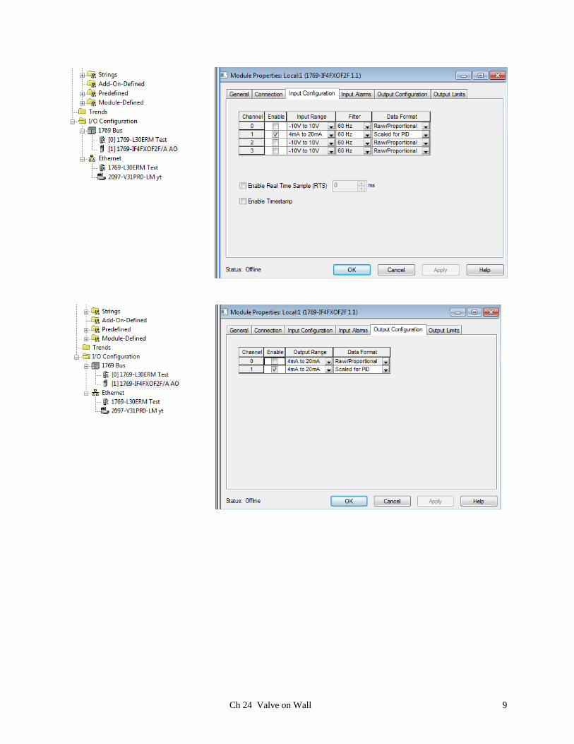
SP or setpoint is mypid.SP. The example screens that follow show the newer IF4XOF2F/A card and
are used to set up the scaling for the present system in the lab.
Ch 24 Valve on Wall 7
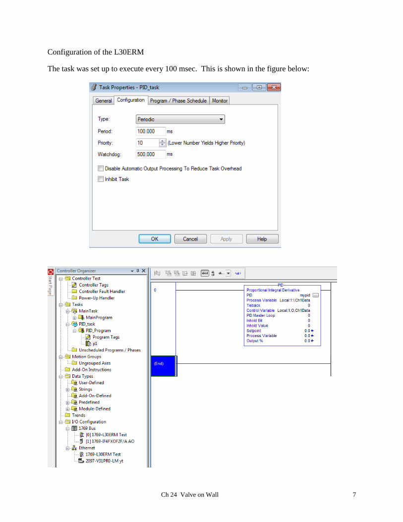
Configuration of the L30ERM
The task was set up to execute every 100 msec. This is shown in the figure below:

Ch 24 Valve on Wall 8
Ch 24 Valve on Wall 9

Ch 24 Valve on Wall 10
The Program Tags for the PID mypid are shown with variable contents. These variables are
useful as tag references used for communicating with the variables through program control.

Ch 24 Valve on Wall 11
The tuning tab shows the variables used to tune the PID block. The Kp, Ki and Kd tuning
constants are probably the best variables for the water valve. These constants should not vary
too much from the numbers shown or the PID block may become unstable.

Ch 24 Valve on Wall 12
PID Configuration
The configuration tab shows the variables used to set up the type of block used. The variables
seen above are the ones used in the download example. There are a number of variables that are
not used.
Ch 24 Valve on Wall 13
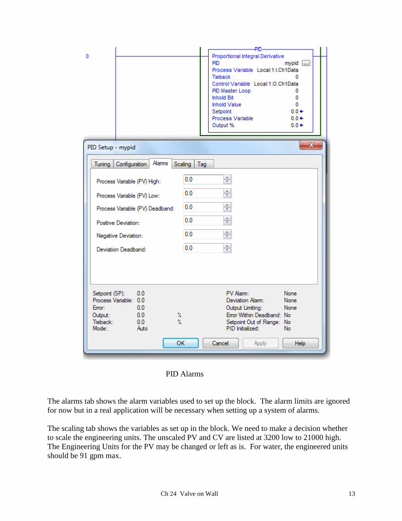
PID Alarms
The alarms tab shows the alarm variables used to set up the block. The alarm limits are ignored
for now but in a real application will be necessary when setting up a system of alarms.
The scaling tab shows the variables as set up in the block. We need to make a decision whether
to scale the engineering units. The unscaled PV and CV are listed at 3200 low to 21000 high.
The Engineering Units for the PV may be changed or left as is. For water, the engineered units
should be 91 gpm max.

Ch 24 Valve on Wall 14
31085
31085
6217
6217
PID Setup

Ch 24 Valve on Wall 15
Tuning Parameters

Ch 24 Valve on Wall 16
Manual Trial
Ch 24 Valve on Wall 17
Ch 24 Valve on Wall 18
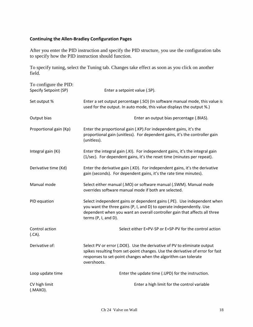
Continuing the Allen-Bradley Configuration Pages
After you enter the PID instruction and specify the PID structure, you use the configuration tabs
to specify how the PID instruction should function.
To specify tuning, select the Tuning tab. Changes take effect as soon as you click on another
field.
To configure the PID: Specify Setpoint (SP) Enter a setpoint value (.SP). Set output % Enter a set output percentage (.SO) (In software manual mode, this value is
used for the output. In auto mode, this value displays the output %.) Output bias Enter an output bias percentage (.BIAS). Proportional gain (Kp) Enter the proportional gain (.KP).For independent gains, it’s the
proportional gain (unitless). For dependent gains, it’s the controller gain (unitless).
Integral gain (Ki) Enter the integral gain (.KI). For independent gains, it’s the integral gain
(1/sec). For dependent gains, it’s the reset time (minutes per repeat). Derivative time (Kd) Enter the derivative gain (.KD). For independent gains, it’s the derivative
gain (seconds). For dependent gains, it’s the rate time minutes). Manual mode Select either manual (.MO) or software manual (.SWM). Manual mode
overrides software manual mode if both are selected. PID equation Select independent gains or dependent gains (.PE). Use independent when
you want the three gains (P, I, and D) to operate independently. Use dependent when you want an overall controller gain that affects all three terms (P, I, and D).
Control action Select either E=PV-SP or E=SP-PV for the control action (.CA). Derivative of: Select PV or error (.DOE). Use the derivative of PV to eliminate output
spikes resulting from set-point changes. Use the derivative of error for fast responses to set-point changes when the algorithm can tolerate overshoots.
Loop update time Enter the update time (.UPD) for the instruction. CV high limit Enter a high limit for the control variable (.MAXO).
Ch 24 Valve on Wall 19
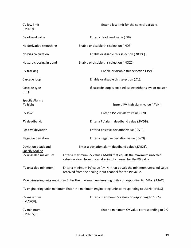
CV low limit Enter a low limit for the control variable (.MINO). Deadband value Enter a deadband value (.DB) No derivative smoothing Enable or disable this selection (.NDF) No bias calculation Enable or disable this selection (.NOBC). No zero crossing in dbnd Enable or disable this selection (.NOZC). PV tracking Enable or disable this selection (.PVT). Cascade loop Enable or disable this selection (.CL). Cascade type If cascade loop is enabled, select either slave or master (.CT). Specify Alarms PV high: Enter a PV high alarm value (.PVH). PV low: Enter a PV low alarm value (.PVL). PV deadband: Enter a PV alarm deadband value (.PVDB). Positive deviation Enter a positive deviation value (.DVP). Negative deviation Enter a negative deviation value (.DVN). Deviation deadband Enter a deviation alarm deadband value (.DVDB). Specify Scaling PV unscaled maximum Enter a maximum PV value (.MAXI) that equals the maximum unscaled
value received from the analog input channel for the PV value. PV unscaled minimum Enter a minimum PV value (.MINI) that equals the minimum unscaled value
received from the analog input channel for the PV value. PV engineering units maximum Enter the maximum engineering units corresponding to .MAXI (.MAXS) PV engineering units minimum Enter the minimum engineering units corresponding to .MINI (.MINS) CV maximum Enter a maximum CV value corresponding to 100% (.MAXCV). CV minimum Enter a minimum CV value corresponding to 0% (.MINCV).

Ch 24 Valve on Wall 20
Tieback maximum Enter a maximum tieback value (.MAXTIE) that equals the maximum unscaled value received from the analog input channel for the tieback value.
Tieback minimum Enter a minimum tieback value (.MINTIE) that equals the minimum
unscaled value received from the analog input channel for the tieback value.
PID Initialized If you change scaling constants during Run mode, turn this off to reinitialize
internal descaling values (.INI)
Shifting to the HMI Program, RS Studio is entered and the Libraries choice and then Face Plates
choice is entered.

Ch 24 Valve on Wall 21
With RSStudio, build a screen from scratch using a face plate. There are a number of face plates
in the template from which to choose.
HMI Loop Face Plate
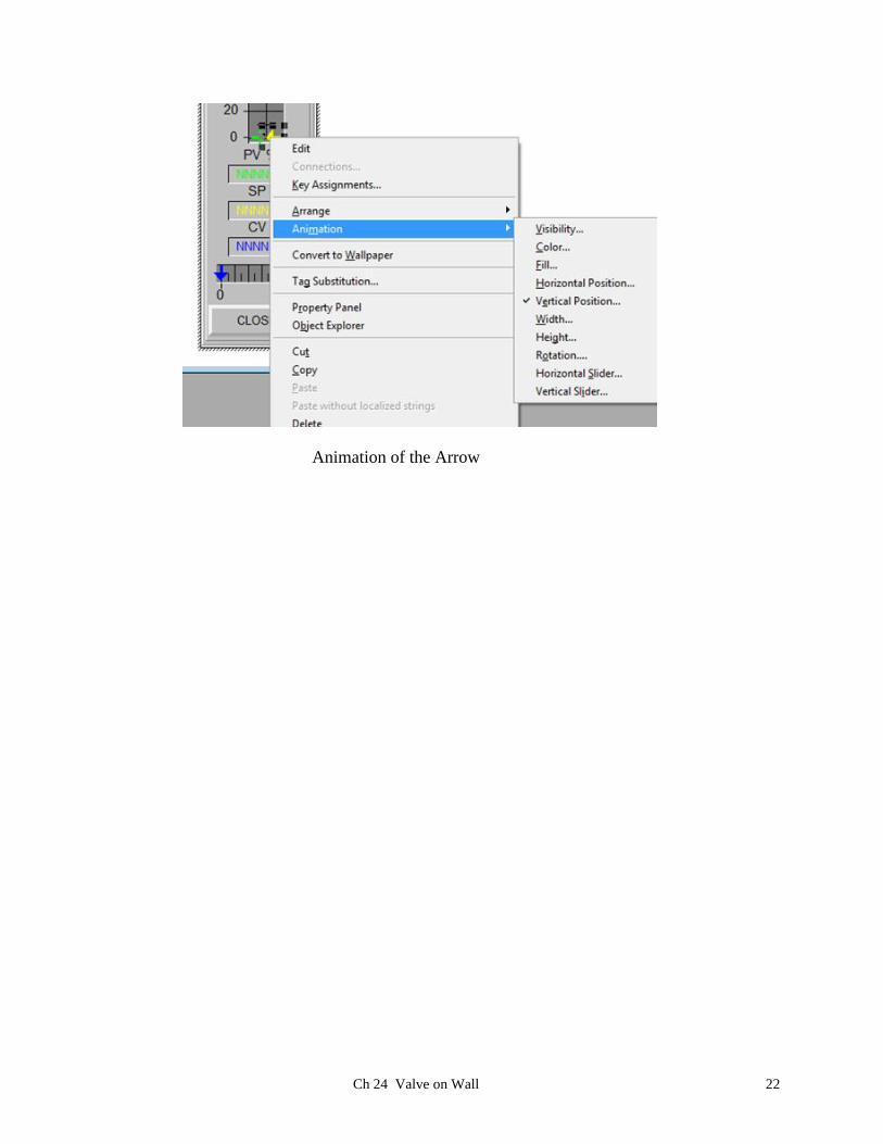
The various parts of the face plate are animated. The next screen shows the details:
Ch 24 Valve on Wall 22
Animation of the Arrow

Ch 24 Valve on Wall 23
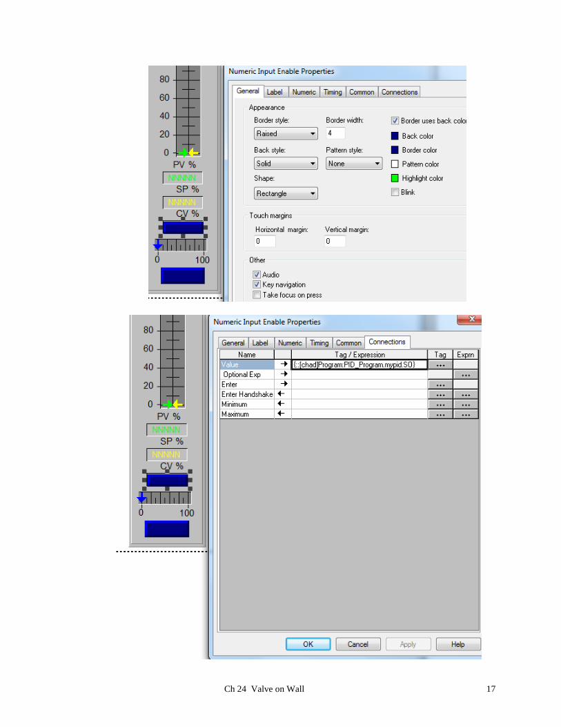
Animation of the Numeric Entry
Ch 24 Valve on Wall 24
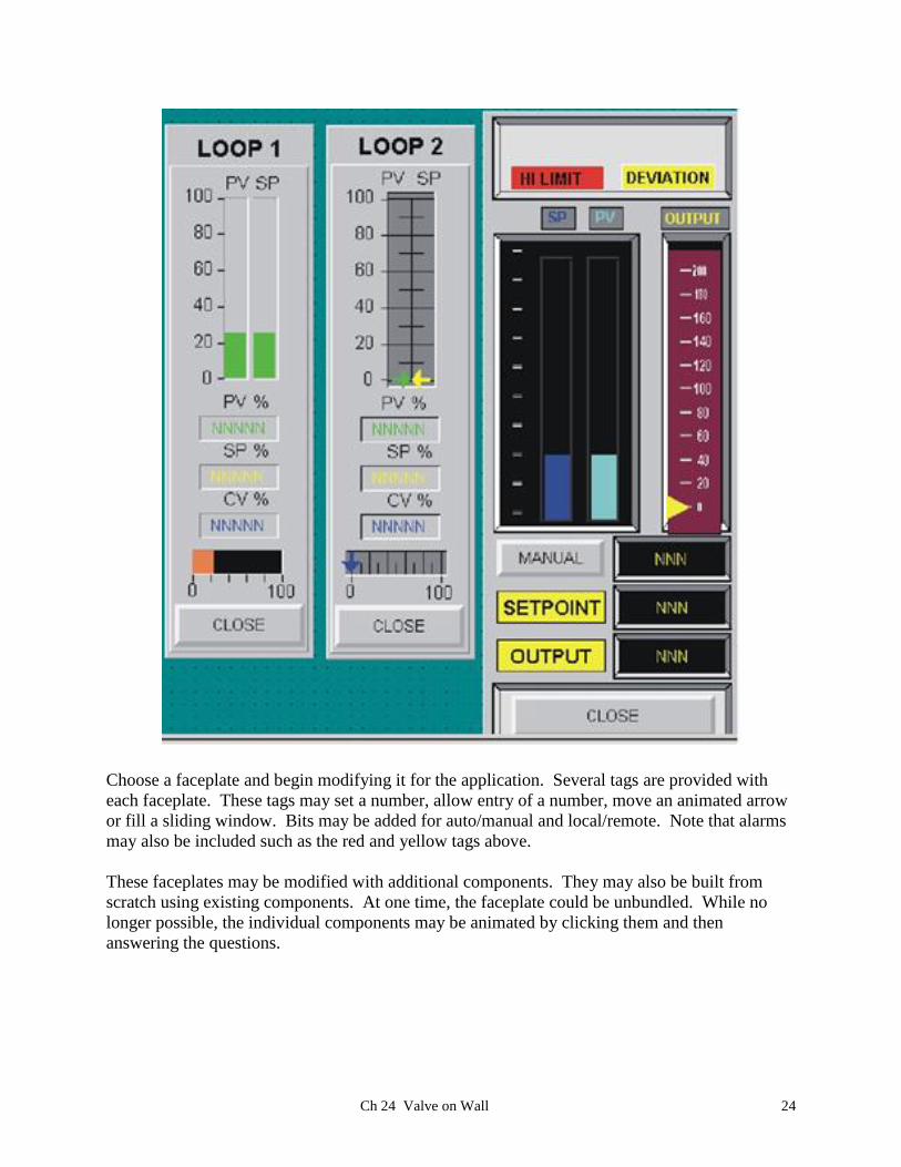
Choose a faceplate and begin modifying it for the application. Several tags are provided with
each faceplate. These tags may set a number, allow entry of a number, move an animated arrow
or fill a sliding window. Bits may be added for auto/manual and local/remote. Note that alarms
may also be included such as the red and yellow tags above.
These faceplates may be modified with additional components. They may also be built from
scratch using existing components. At one time, the faceplate could be unbundled. While no
longer possible, the individual components may be animated by clicking them and then
answering the questions.