Embed Size (px)
Citation preview
Copyright © 2010 Pearson Education, Inc.
Lecture Outline
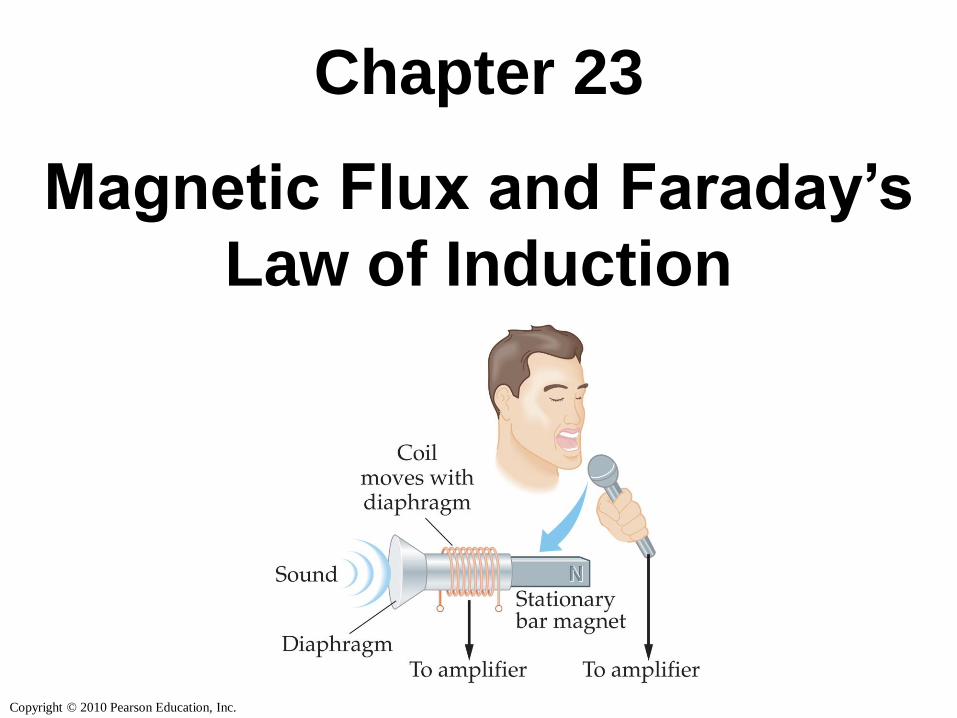
Chapter 23
Physics, 4th Edition
James S. Walker
Copyright © 2010 Pearson Education, Inc.
Chapter 23
Magnetic Flux and Faraday’s
Law of Induction
Copyright © 2010 Pearson Education, Inc.
Units of Chapter 23
• Induced Electromotive Force
• Magnetic Flux
• Faraday’s Law of Induction
• Lenz’s Law
• Mechanical Work and Electrical Energy
• Generators and Motors
Copyright © 2010 Pearson Education, Inc.
Units of Chapter 23
• Inductance
• RL Circuits
• Energy Stored in a Magnetic Field
• Transformers
Copyright © 2010 Pearson Education, Inc.
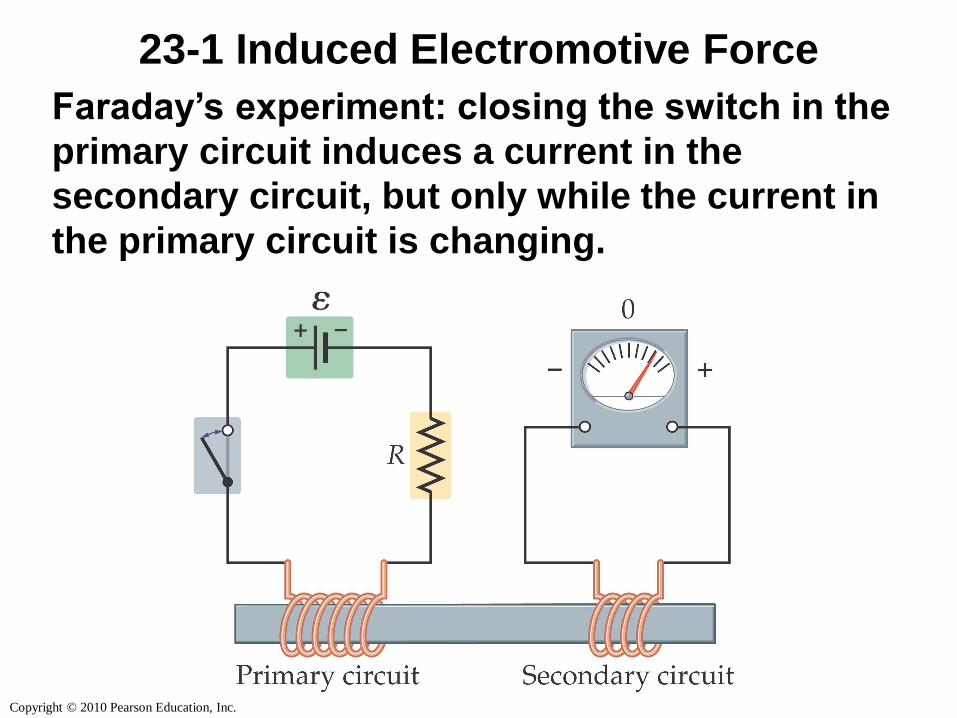
23-1 Induced Electromotive Force
Faraday’s experiment: closing the switch in the
primary circuit induces a current in the
secondary circuit, but only while the current in
the primary circuit is changing.
Copyright © 2010 Pearson Education, Inc.
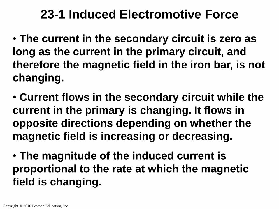
23-1 Induced Electromotive Force
• The current in the secondary circuit is zero as
long as the current in the primary circuit, and
therefore the magnetic field in the iron bar, is not
changing.
• Current flows in the secondary circuit while the
current in the primary is changing. It flows in
opposite directions depending on whether the
magnetic field is increasing or decreasing.
• The magnitude of the induced current is
proportional to the rate at which the magnetic
field is changing.
Copyright © 2010 Pearson Education, Inc.
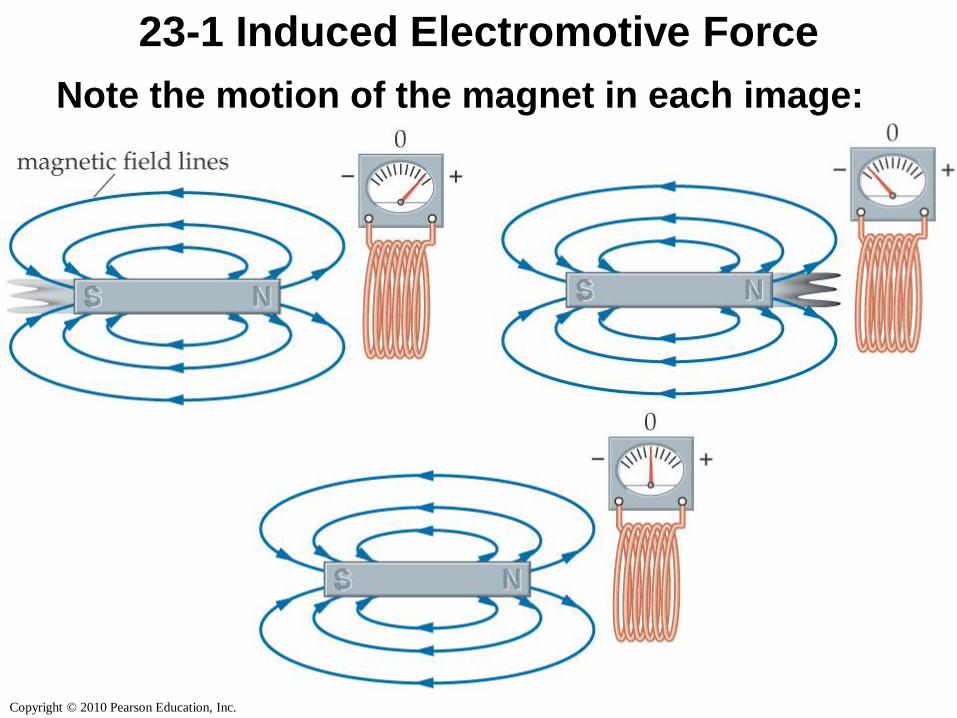
23-1 Induced Electromotive Force
Note the motion of the magnet in each image:
Copyright © 2010 Pearson Education, Inc.
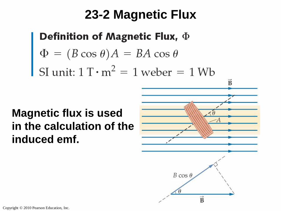
23-2 Magnetic Flux
Magnetic flux is used
in the calculation of the
induced emf.
Copyright © 2010 Pearson Education, Inc.
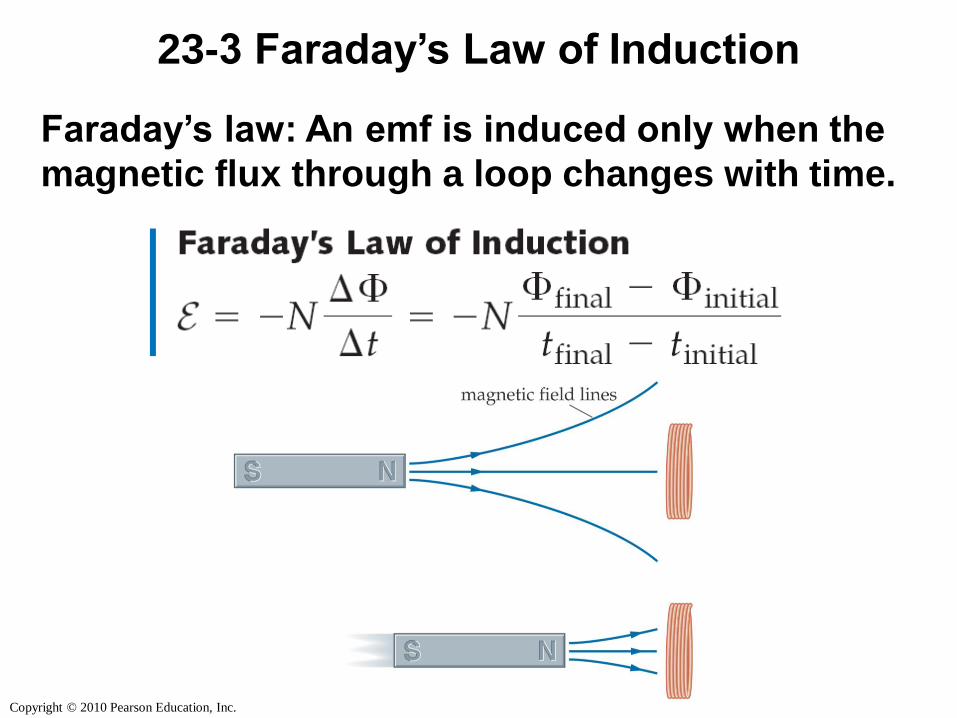
23-3 Faraday’s Law of Induction
Faraday’s law: An emf is induced only when the
magnetic flux through a loop changes with time.
Copyright © 2010 Pearson Education, Inc.
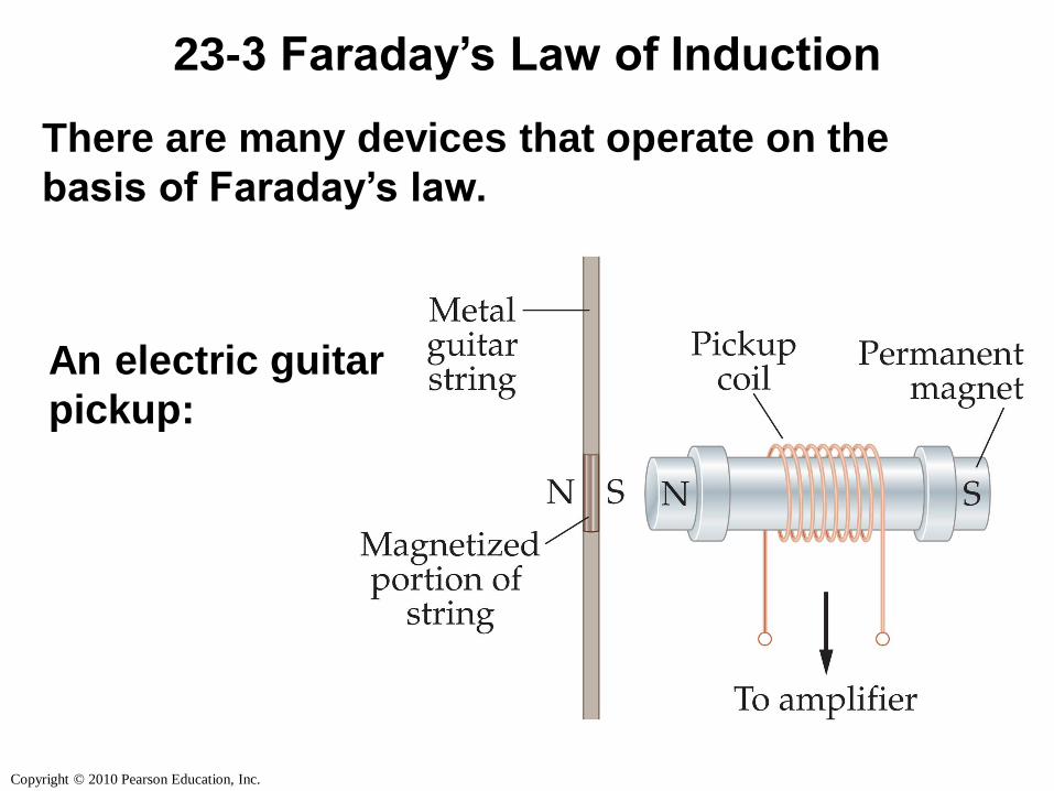
23-3 Faraday’s Law of Induction
There are many devices that operate on the
basis of Faraday’s law.
An electric guitar
pickup:
Copyright © 2010 Pearson Education, Inc.
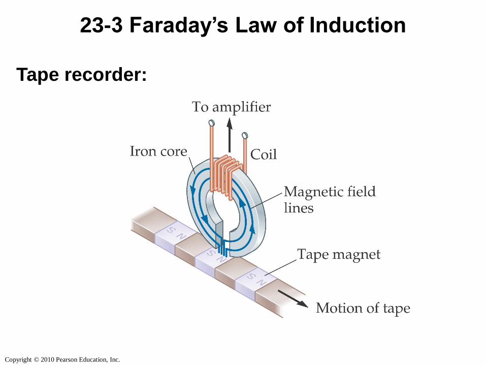
23-3 Faraday’s Law of Induction
Tape recorder:
Copyright © 2010 Pearson Education, Inc.
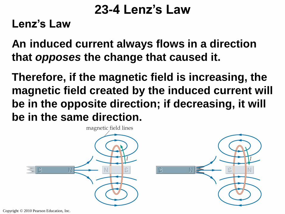
23-4 Lenz’s LawLenz’s Law
An induced current always flows in a direction
that opposes the change that caused it.
Therefore, if the magnetic field is increasing, the
magnetic field created by the induced current will
be in the opposite direction; if decreasing, it will
be in the same direction.
Copyright © 2010 Pearson Education, Inc.
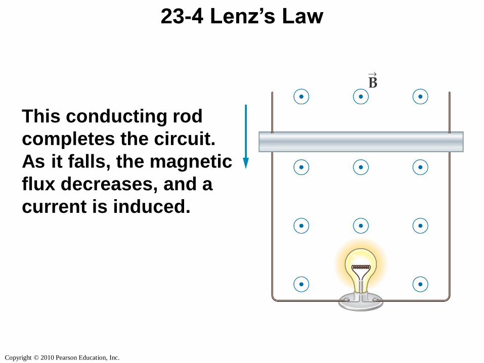
23-4 Lenz’s Law
This conducting rod
completes the circuit.
As it falls, the magnetic
flux decreases, and a
current is induced.
Copyright © 2010 Pearson Education, Inc.
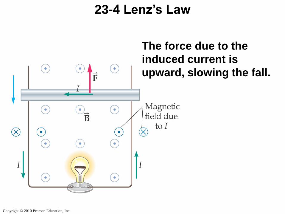
23-4 Lenz’s Law
The force due to the
induced current is
upward, slowing the fall.
Copyright © 2010 Pearson Education, Inc.
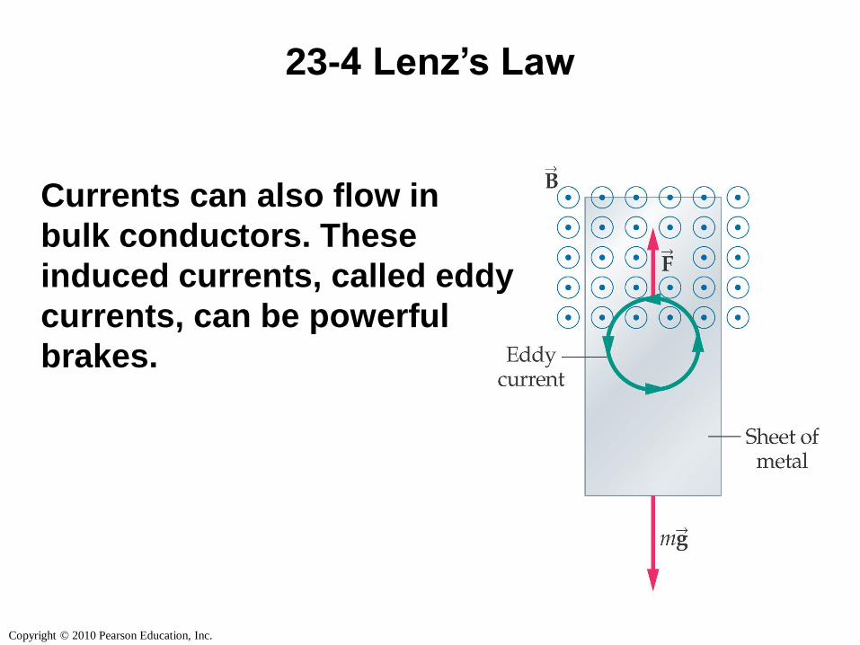
23-4 Lenz’s Law
Currents can also flow in
bulk conductors. These
induced currents, called eddy
currents, can be powerful
brakes.
Copyright © 2010 Pearson Education, Inc.
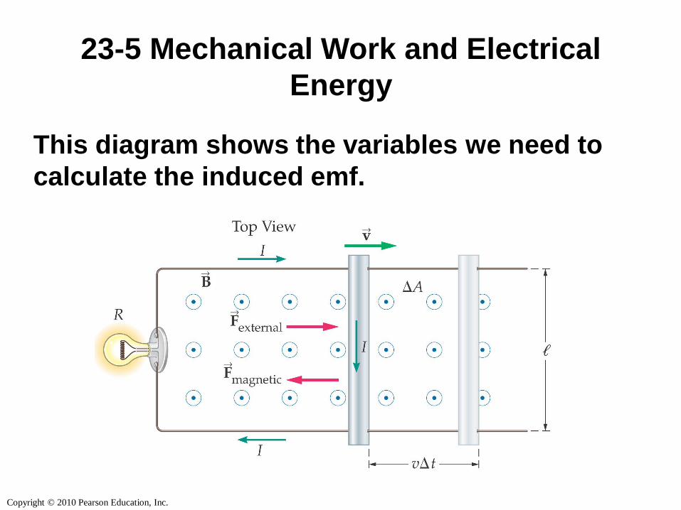
23-5 Mechanical Work and Electrical
Energy
This diagram shows the variables we need to
calculate the induced emf.
Copyright © 2010 Pearson Education, Inc.
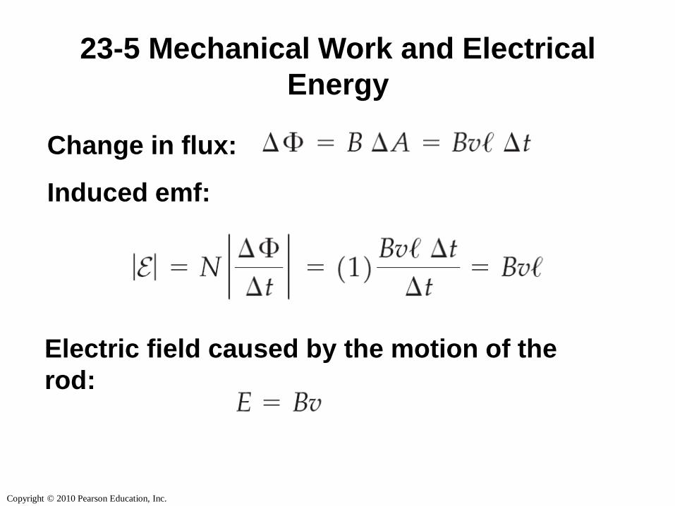
23-5 Mechanical Work and Electrical
Energy
Change in flux:
Induced emf:
Electric field caused by the motion of the
rod:
Copyright © 2010 Pearson Education, Inc.
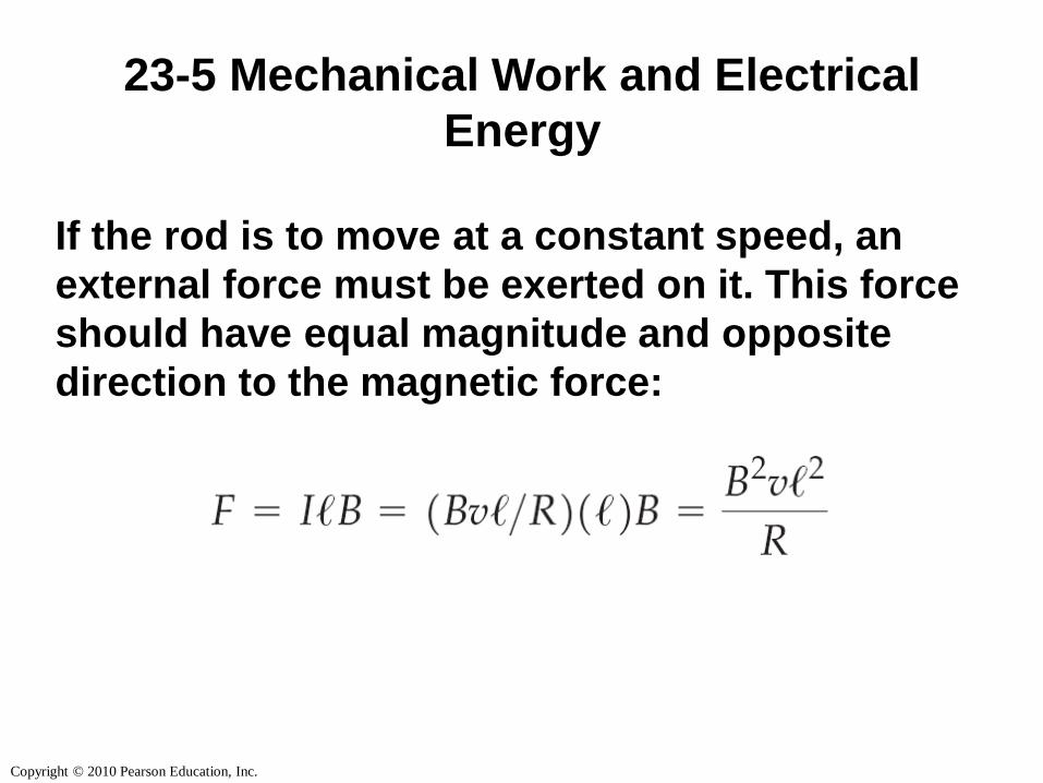
23-5 Mechanical Work and Electrical
Energy
If the rod is to move at a constant speed, an
external force must be exerted on it. This force
should have equal magnitude and opposite
direction to the magnetic force:
Copyright © 2010 Pearson Education, Inc.
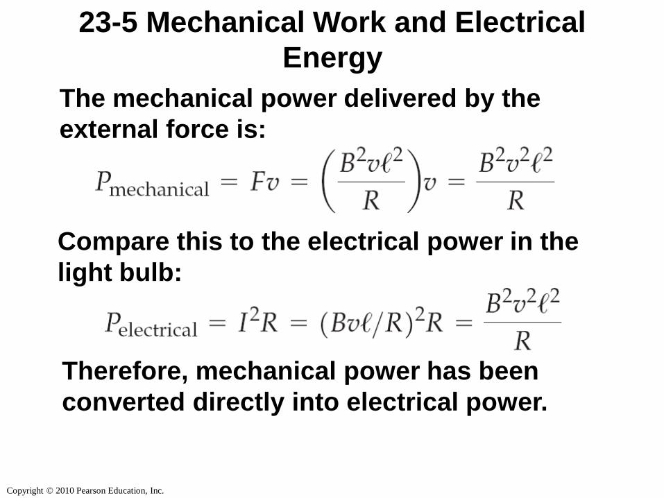
23-5 Mechanical Work and Electrical
Energy
The mechanical power delivered by the
external force is:
Compare this to the electrical power in the
light bulb:
Therefore, mechanical power has been
converted directly into electrical power.
Copyright © 2010 Pearson Education, Inc.
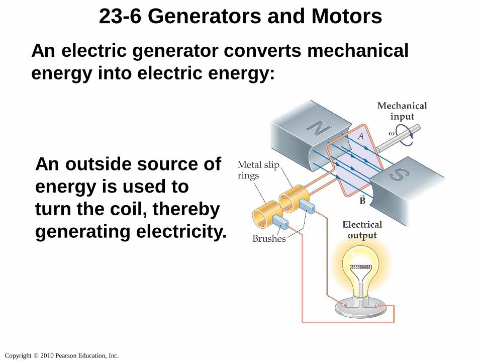
23-6 Generators and Motors
An electric generator converts mechanical
energy into electric energy:
An outside source of
energy is used to
turn the coil, thereby
generating electricity.
Copyright © 2010 Pearson Education, Inc.
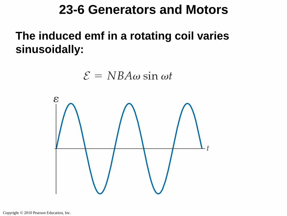
23-6 Generators and Motors
The induced emf in a rotating coil varies
sinusoidally:
Copyright © 2010 Pearson Education, Inc.
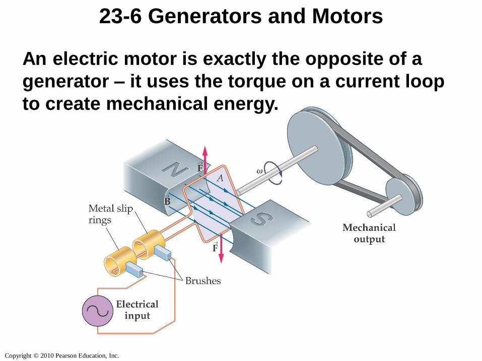
23-6 Generators and Motors
An electric motor is exactly the opposite of a
generator – it uses the torque on a current loop
to create mechanical energy.
Copyright © 2010 Pearson Education, Inc.
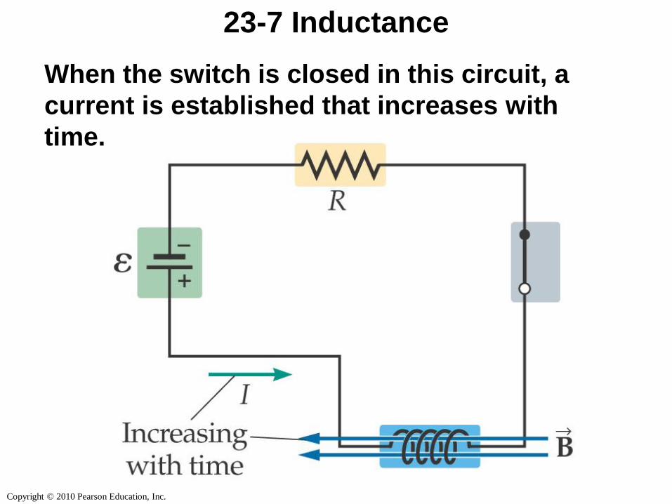
23-7 Inductance
When the switch is closed in this circuit, a
current is established that increases with
time.
Copyright © 2010 Pearson Education, Inc.
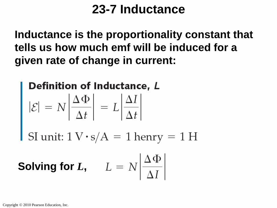
23-7 Inductance
Inductance is the proportionality constant that
tells us how much emf will be induced for a
given rate of change in current:
Solving for L,
Copyright © 2010 Pearson Education, Inc.
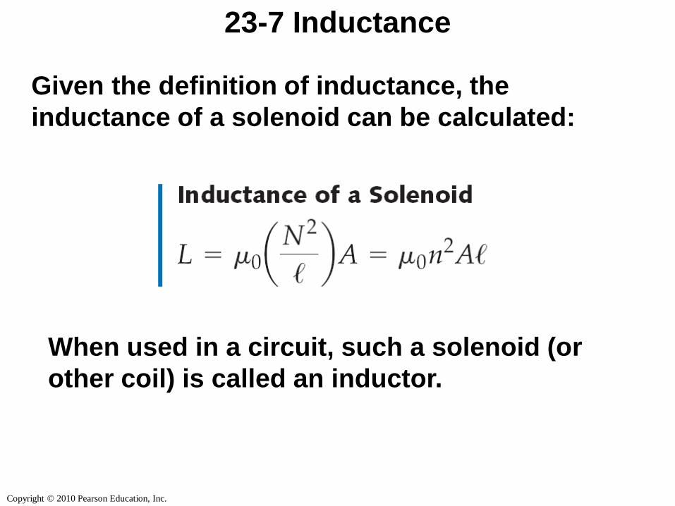
23-7 Inductance
Given the definition of inductance, the
inductance of a solenoid can be calculated:
When used in a circuit, such a solenoid (or
other coil) is called an inductor.
Copyright © 2010 Pearson Education, Inc.
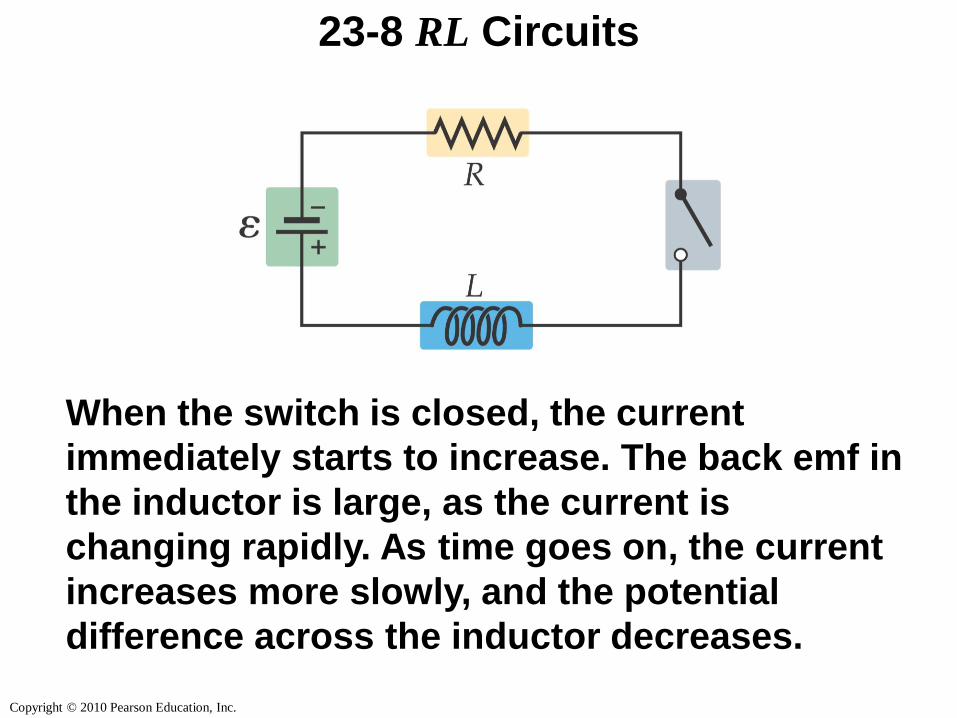
23-8 RL Circuits
When the switch is closed, the current
immediately starts to increase. The back emf in
the inductor is large, as the current is
changing rapidly. As time goes on, the current
increases more slowly, and the potential
difference across the inductor decreases.
Copyright © 2010 Pearson Education, Inc.
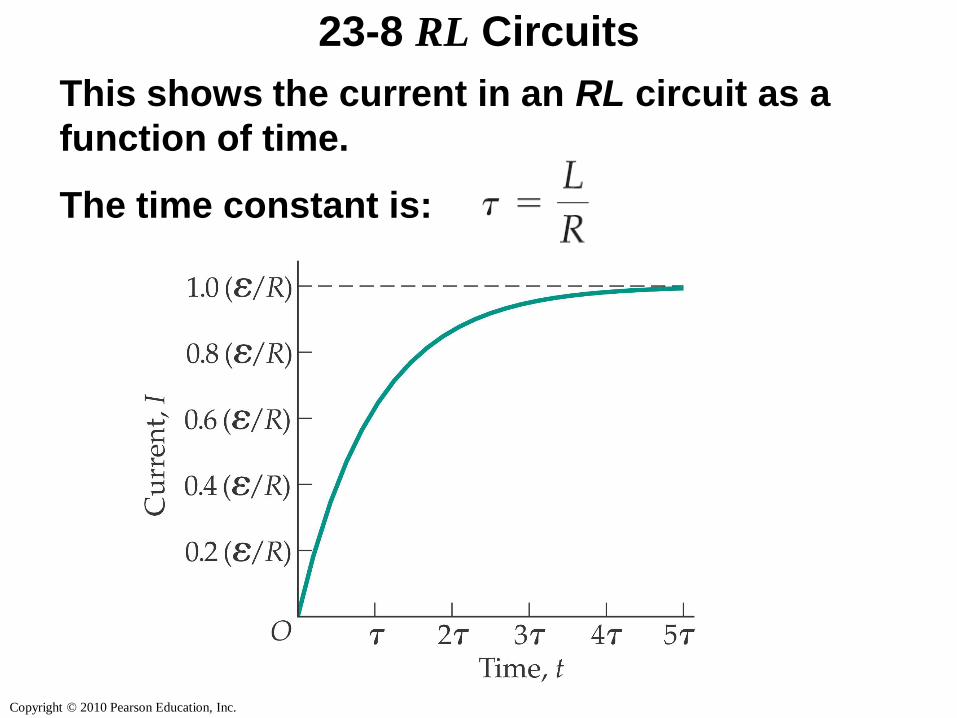
23-8 RL Circuits
This shows the current in an RL circuit as a
function of time.
The time constant is:
Copyright © 2010 Pearson Education, Inc.
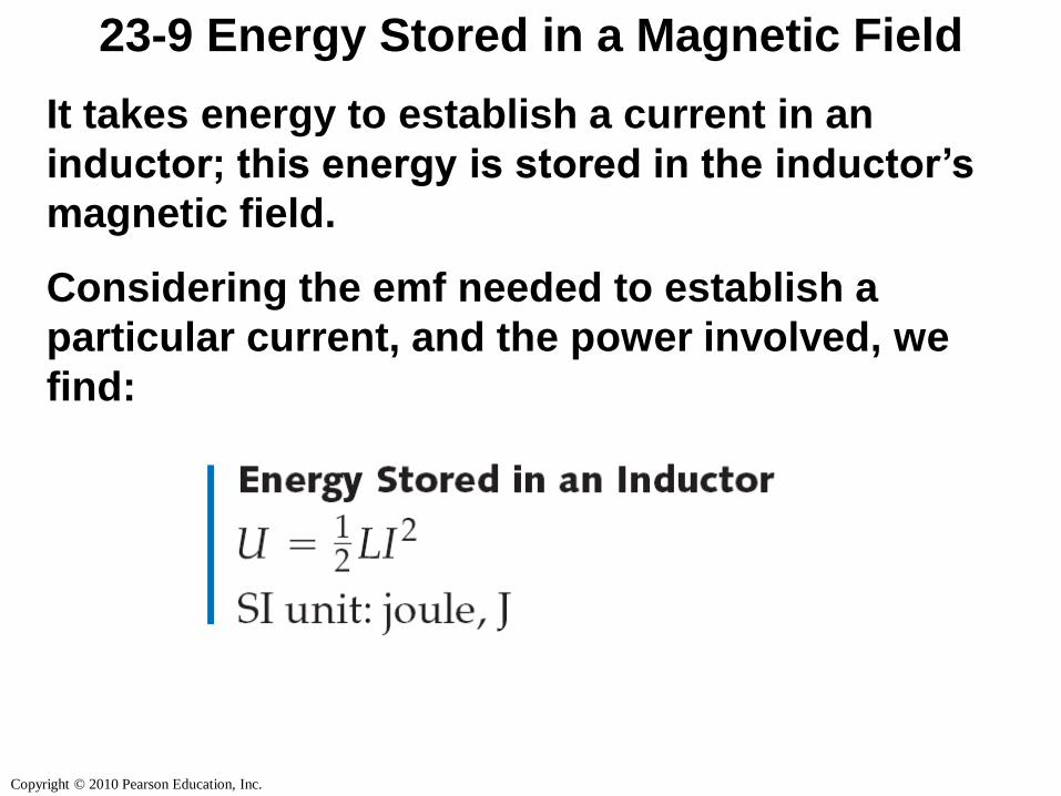
23-9 Energy Stored in a Magnetic Field
It takes energy to establish a current in an
inductor; this energy is stored in the inductor’s
magnetic field.
Considering the emf needed to establish a
particular current, and the power involved, we
find:
Copyright © 2010 Pearson Education, Inc.
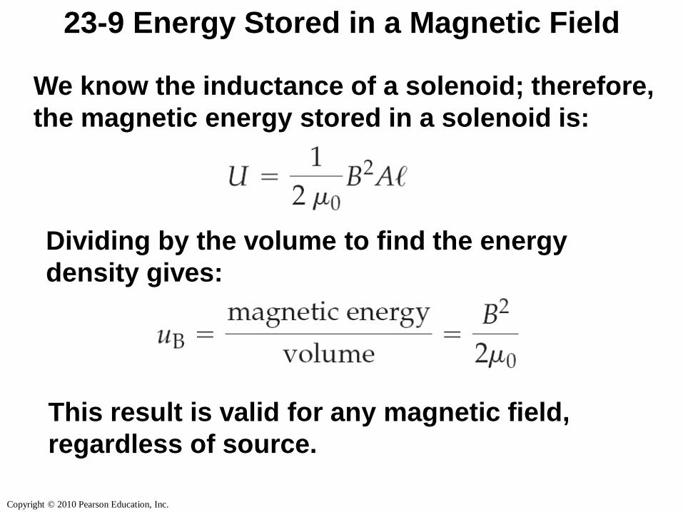
23-9 Energy Stored in a Magnetic Field
We know the inductance of a solenoid; therefore,
the magnetic energy stored in a solenoid is:
Dividing by the volume to find the energy
density gives:
This result is valid for any magnetic field,
regardless of source.
Copyright © 2010 Pearson Education, Inc.
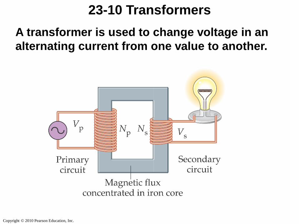
23-10 Transformers
A transformer is used to change voltage in an
alternating current from one value to another.
Copyright © 2010 Pearson Education, Inc.
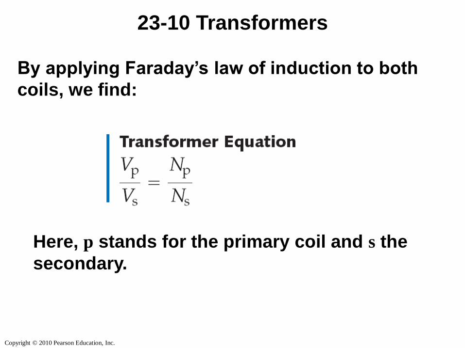
23-10 Transformers
By applying Faraday’s law of induction to both
coils, we find:
Here, p stands for the primary coil and s the
secondary.
Copyright © 2010 Pearson Education, Inc.
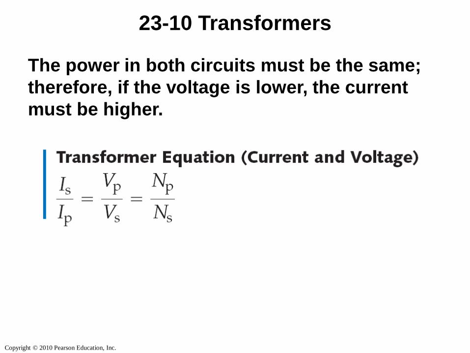
23-10 Transformers
The power in both circuits must be the same;
therefore, if the voltage is lower, the current
must be higher.
Copyright © 2010 Pearson Education, Inc.
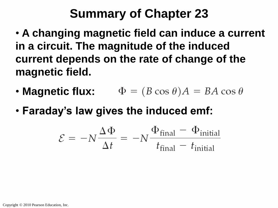
Summary of Chapter 23
• A changing magnetic field can induce a current
in a circuit. The magnitude of the induced
current depends on the rate of change of the
magnetic field.
• Magnetic flux:
• Faraday’s law gives the induced emf:
Copyright © 2010 Pearson Education, Inc.
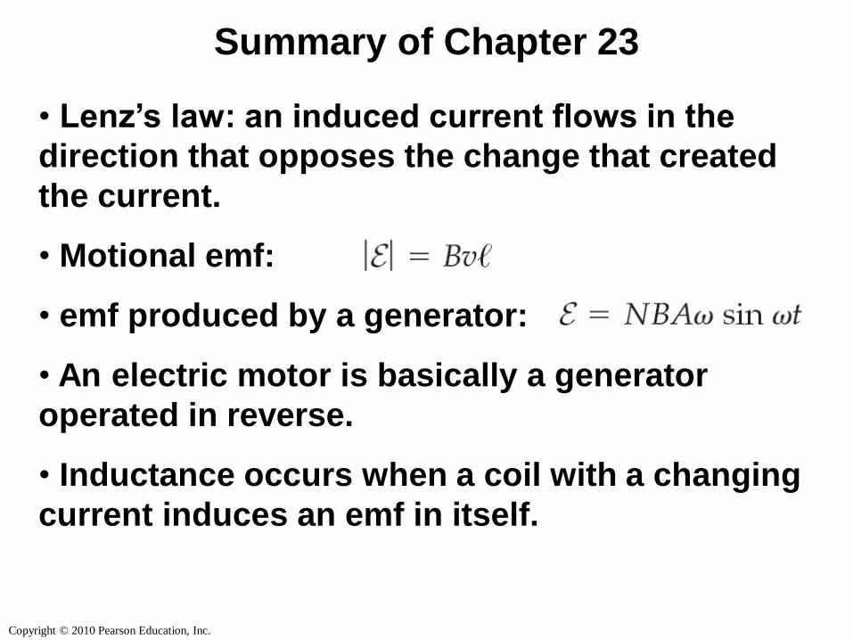
Summary of Chapter 23
• Lenz’s law: an induced current flows in the
direction that opposes the change that created
the current.
• Motional emf:
• emf produced by a generator:
• An electric motor is basically a generator
operated in reverse.
• Inductance occurs when a coil with a changing
current induces an emf in itself.
Copyright © 2010 Pearson Education, Inc.
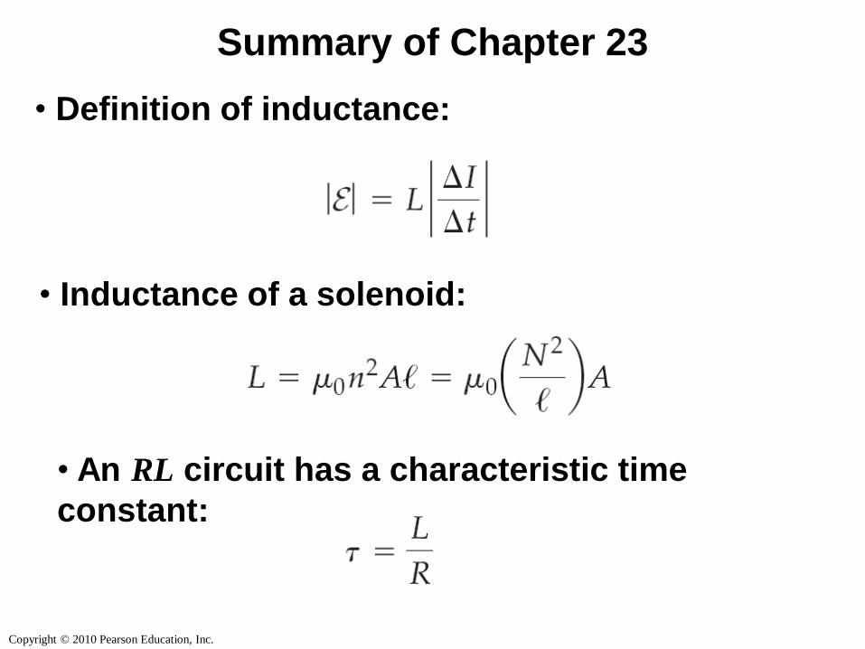
Summary of Chapter 23
• Definition of inductance:
• Inductance of a solenoid:
• An RL circuit has a characteristic time
constant:
Copyright © 2010 Pearson Education, Inc.
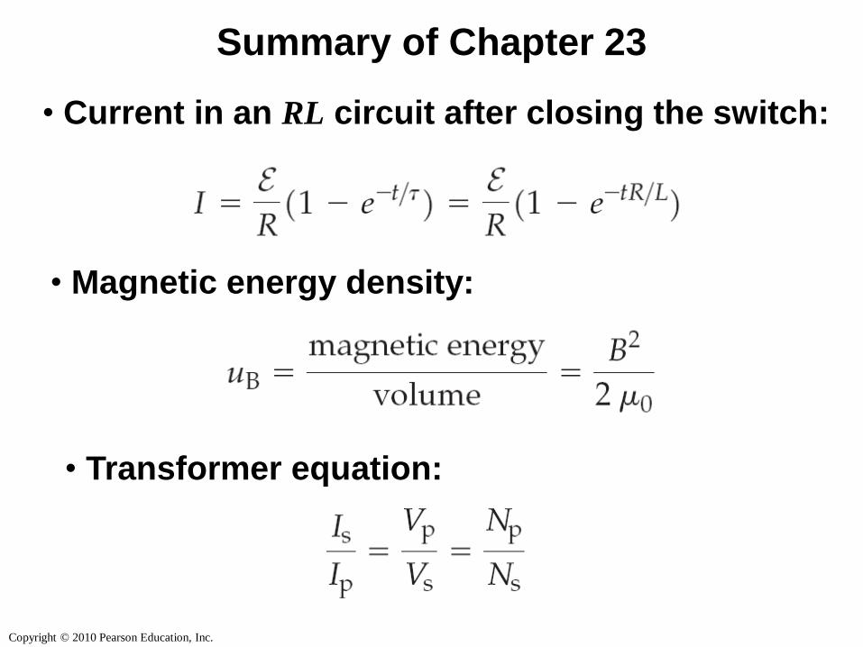
Summary of Chapter 23
• Current in an RL circuit after closing the switch:
• Magnetic energy density:
• Transformer equation: