Embed Size (px)
Citation preview
Chapter 23 Geotechnical Reporting and Documentation
23.1 Overview and General RequirementsThe Geotechnical Office, and consultants working on WSDOT projects, produce geotechnical reports and design memorandums in support of project definition, project design, and final PS&E development (see Chapter 1). Also produced are project specific Special Provisions, plan details, boring logs, Summary of Geotechnical Conditions, and the final project geotechnical documentation. Information developed to support these geotechnical documents are retained in the Geotechnical Office files. The information includes project site data, drilling inspector’s field logs, test results, design calculations, and construction support documents. This chapter provides standards for the development and detailed checklists for review of these documents and records, with the exception of borings logs, which are covered in Chapter 4, Materials Source Reports, which are covered in Chapter 21, and Geotechnical Baseline Reports (GBR), which are covered in Chapter 22. The general format, review, and certification requirements for these documents are provided in Chapter 1.
The Region Materials Offices also produce reports that contain geotechnical information and recommendations as discussed in Chapter 1 (e.g., Region Soil Reports). As applicable, the standards contained within this chapter should also be used for the development of these regional reports.
Documents and project geotechnical documentation/records produced by the Geotechnical Office, and consultants working on WSDOT projects, shall meet as applicable the informational requirements listed in the following FHWA manual:• FHWA, 2003, Checklist and Guidelines for Review of Geotechnical Reports
and Preliminary Plans and Specifications, Publication No. FHWA ED-88-053, Updated edition.
This FHWA manual also includes a PS&E review checklist. The PS&E review checklist contained in this FHWA manual should be used to supplement the WSDOT Geotechnical Office PS&E review checklist provided in Appendix 23-A. These checklists should be used as the basis for evaluating the completeness of the PS&E regarding incorporation of the project geotechnical recommendations and geotechnical data included in the geotechnical report for the project.
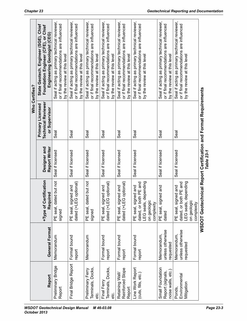
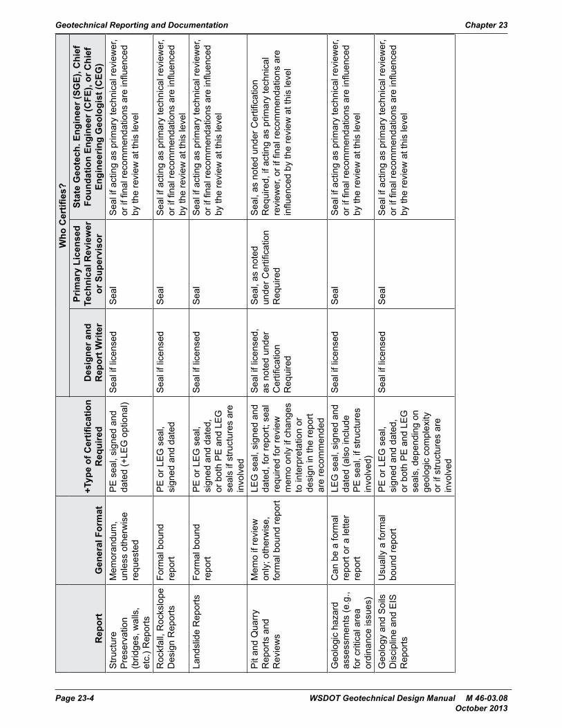
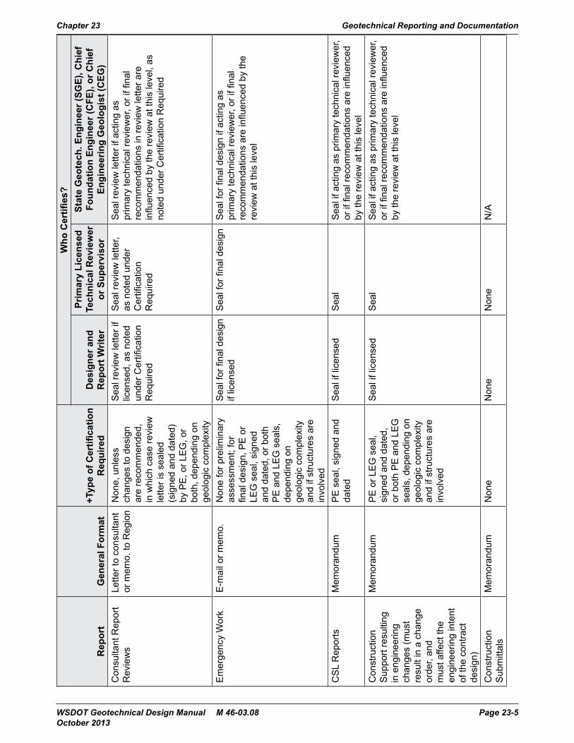
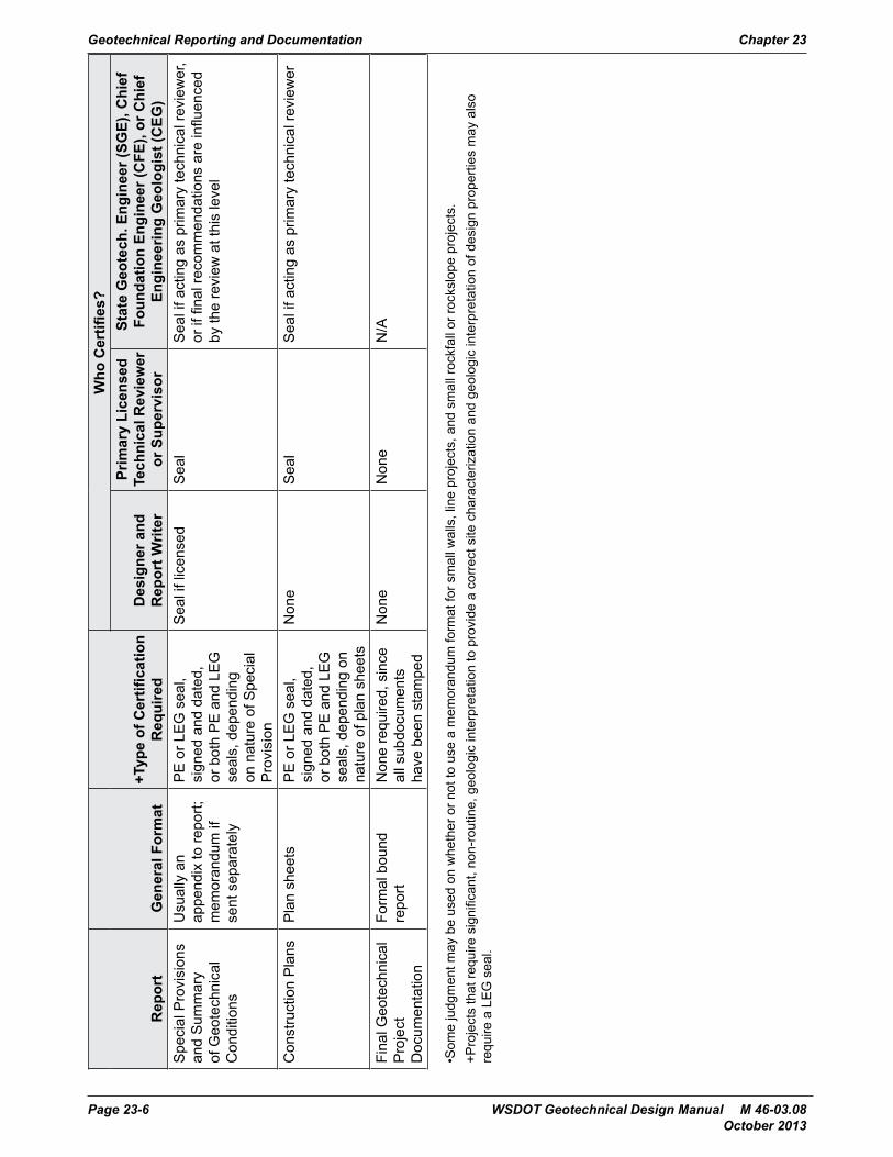
23.2 Report Certification and General FormatTable 23-1 provides a listing of reports produced by the Geotechnical Office, the type of certification needed to be consistent with the certification policies provided in Chapter 1 and WSDOT Executive Order E1010.00, and the general format that would typically be used. For formal geotechnical reports, the signatures and stamps will be located on the front of the report. For memorandums, a signature/stamp page will be added to the back of the memorandum. All those involved in the engineering for the project must sign these documents (i.e., the designer(s), the reviewer(s), and the State Geotechnical Engineer, or the individual delegated to act on behalf the State Geotechnical Engineer), and if licensed and as appropriate, certify the documents as summarized in Table 23-1.
WSDOT Geotechnical Design Manual M 46-03.08 Page 23-1 October 2013
For reports that cover individual project elements, a geotechnical design memorandum may suffice, with the exception of bridge reports and major unstable slope design reports, in which case a formal geotechnical report should be issued. For project reports, a formal geotechnical report should be issued. For geotechnical reports that are sent to agencies outside of WSDOT, a letter report format will be used in place of the memorandum format. Alternatively, a formal report transmitted with a letter may be used.
E-mail may be used for geotechnical reporting in certain circumstances. E-mails may be used to transmit review of construction submittals, and Region soil reports sent to the Geotechnical Office for concurrence. E-mails may also be used to transmit conceptual foundation or other conceptual geotechnical recommendations. In both cases, a print-out of the e-mail should be included in the project file. For time critical geotechnical designs sent by e-mail that are not conceptual, the e-mail should be followed up with a stamped memorandum or report as soon as possible. A copy of the e-mail should also be included in the project file.
For reports produced by others outside of WSDOT, the certification requirements described herein are applicable, but the specific report format will be as mutually agreed upon by the Geotechnical Office and those who are producing the report.
Geotechnical Reporting and Documentation Chapter 23
Page 23-2 WSDOT Geotechnical Design Manual M 46-03.08 October 2013
Rep
ort
General Format
+Type of Certifi
catio
n R
equi
red
Who
Certifi
es?
Des
igne
r and
R
epor
t Writ
er
Primary Licensed
Technical R
eviewer
or S
uper
viso
r
State Geotech. E
ngineer (SG
E), C
hief
Foun
datio
n En
gineer (C
FE), or Chief
Engineering Geologist (C
EG)
Pre
limin
ary
Brid
ge
Rep
ort
Mem
oran
dum
PE
sea
l, da
ted
but n
ot
sign
edS
eal i
f lic
ense
dS
eal
Sea
l if a
ctin
g as
prim
ary
tech
nica
l rev
iew
er,
or if
fina
l rec
omm
enda
tions
are
influ
ence
d by
the
revi
ew a
t thi
s le
vel
Fina
l Brid
ge R
epor
tFo
rmal
bou
nd
repo
rtP
E s
eal,
sign
ed a
nd
date
d (+
LEG
opt
iona
l)S
eal i
f lic
ense
dS
eal
Sea
l if a
ctin
g as
prim
ary
tech
nica
l rev
iew
er,
or if
fina
l rec
omm
enda
tions
are
influ
ence
d by
the
revi
ew a
t thi
s le
vel
Pre
limin
ary
Ferr
y Te
rmin
als,
Doc
ks,
etc.
Mem
oran
dum
PE
sea
l, da
ted
but n
ot
sign
edS
eal i
f lic
ense
dS
eal
Sea
l if a
ctin
g as
prim
ary
tech
nica
l rev
iew
er,
or if
fina
l rec
omm
enda
tions
are
influ
ence
d by
the
revi
ew a
t thi
s le
vel
Fina
l Fer
ry
Term
inal
s, D
ocks
, et
c.
Form
al b
ound
re
port
PE
sea
l, si
gned
and
da
ted
(+LE
G o
ptio
nal)
Sea
l if l
icen
sed
Sea
lS
eal i
f act
ing
as p
rimar
y te
chni
cal r
evie
wer
, or
if fi
nal r
ecom
men
datio
ns a
re in
fluen
ced
by th
e re
view
at t
his
leve
lR
etai
ning
Wal
l/R
einf
orce
d S
lope
R
epor
t
Form
al b
ound
re
port
PE
sea
l, si
gned
and
da
ted
(+LE
G o
ptio
nal)
Sea
l if l
icen
sed
Sea
lS
eal i
f act
ing
as p
rimar
y te
chni
cal r
evie
wer
, or
if fi
nal r
ecom
men
datio
ns a
re in
fluen
ced
by th
e re
view
at t
his
leve
lLi
ne W
ork
Rep
ort
(cut
s, fi
lls, e
tc.)
Form
al b
ound
re
port
PE
sea
l, si
gned
and
da
ted,
or b
oth
PE
and
LE
G s
eals
, dep
endi
ng
on g
eolo
gic
com
plex
ity
Sea
l if l
icen
sed
Sea
lS
eal i
f act
ing
as p
rimar
y te
chni
cal r
evie
wer
, or
if fi
nal r
ecom
men
datio
ns a
re in
fluen
ced
by th
e re
view
at t
his
leve
l
Sm
all F
ound
atio
n R
epor
t (si
gnal
s,
nois
e w
alls
, etc
.)
Mem
oran
dum
, un
less
oth
erw
ise
requ
este
d
PE
sea
l, si
gned
and
da
ted
Sea
l if l
icen
sed
Sea
lS
eal i
f act
ing
as p
rimar
y te
chni
cal r
evie
wer
, or
if fi
nal r
ecom
men
datio
ns a
re in
fluen
ced
by th
e re
view
at t
his
leve
lP
onds
, E
nviro
nmen
tal
Miti
gatio
n
Mem
oran
dum
, un
less
oth
erw
ise
requ
este
d
PE
sea
l, si
gned
and
da
ted,
or b
oth
PE
and
LE
G s
eals
, dep
endi
ng
on g
eolo
gic
com
plex
ity
Sea
l if l
icen
sed
Sea
lS
eal i
f act
ing
as p
rimar
y te
chni
cal r
evie
wer
, or
if fi
nal r
ecom
men
datio
ns a
re in
fluen
ced
by th
e re
view
at t
his
leve
l
WSD
OT Geotechnical R
eport C
ertifi
catio
n and Fo
rmat Requirements
Tabl
e 23
-1
Chapter 23 Geotechnical Reporting and Documentation
WSDOT Geotechnical Design Manual M 46-03.08 Page 23-3 October 2013
Rep
ort
General Format
+Type of Certifi
catio
n R
equi
red
Who
Certifi
es?
Des
igne
r and
R
epor
t Writ
er
Primary Licensed
Technical R
eviewer
or S
uper
viso
r
State Geotech. E
ngineer (SG
E), C
hief
Foun
datio
n En
gineer (C
FE), or Chief
Engineering Geologist (C
EG)
Stru
ctur
e P
rese
rvat
ion
(brid
ges,
wal
ls,
etc.
) Rep
orts
Mem
oran
dum
, un
less
oth
erw
ise
requ
este
d
PE
sea
l, si
gned
and
da
ted
(+LE
G o
ptio
nal)
Sea
l if l
icen
sed
Sea
lS
eal i
f act
ing
as p
rimar
y te
chni
cal r
evie
wer
, or
if fi
nal r
ecom
men
datio
ns a
re in
fluen
ced
by th
e re
view
at t
his
leve
l
Roc
kfal
l, R
ocks
lope
D
esig
n R
epor
tsFo
rmal
bou
nd
repo
rtP
E o
r LE
G s
eal,
sign
ed a
nd d
ated
Sea
l if l
icen
sed
Sea
lS
eal i
f act
ing
as p
rimar
y te
chni
cal r
evie
wer
, or
if fi
nal r
ecom
men
datio
ns a
re in
fluen
ced
by th
e re
view
at t
his
leve
lLa
ndsl
ide
Rep
orts
Form
al b
ound
re
port
PE
or L
EG
sea
l, si
gned
and
dat
ed,
or b
oth
PE
and
LE
G
seal
s if
stru
ctur
es a
re
invo
lved
Sea
l if l
icen
sed
Sea
lS
eal i
f act
ing
as p
rimar
y te
chni
cal r
evie
wer
, or
if fi
nal r
ecom
men
datio
ns a
re in
fluen
ced
by th
e re
view
at t
his
leve
l
Pit
and
Qua
rry
Rep
orts
and
R
evie
ws
Mem
o if
revi
ew
only
; oth
erw
ise,
fo
rmal
bou
nd re
port
LEG
sea
l, si
gned
and
da
ted,
for r
epor
t; se
al
requ
ired
for r
evie
w
mem
o on
ly if
cha
nges
to
inte
rpre
tatio
n or
de
sign
in th
e re
port
are
reco
mm
ende
d
Sea
l if l
icen
sed,
as
not
ed u
nder
C
ertifi
catio
n R
equi
red
Sea
l, as
not
ed
unde
r Cer
tifica
tion
Req
uire
d
Sea
l, as
not
ed u
nder
Cer
tifica
tion
Req
uire
d, if
act
ing
as p
rimar
y te
chni
cal
revi
ewer
, or i
f fina
l rec
omm
enda
tions
are
in
fluen
ced
by th
e re
view
at t
his
leve
l
Geo
logi
c ha
zard
as
sess
men
ts (e
.g.,
for c
ritic
al a
rea
ordi
nanc
e is
sues
)
Can
be
a fo
rmal
re
port
or a
lette
r re
port
LEG
sea
l, si
gned
and
da
ted
(als
o in
clud
e P
E s
eal,
if st
ruct
ures
in
volv
ed)
Sea
l if l
icen
sed
Sea
lS
eal i
f act
ing
as p
rimar
y te
chni
cal r
evie
wer
, or
if fi
nal r
ecom
men
datio
ns a
re in
fluen
ced
by th
e re
view
at t
his
leve
l
Geo
logy
and
Soi
ls
Dis
cipl
ine
and
EIS
R
epor
ts
Usu
ally
a fo
rmal
bo
und
repo
rtP
E o
r LE
G s
eal,
sign
ed a
nd d
ated
, or
bot
h P
E a
nd L
EG
se
als,
dep
endi
ng o
n ge
olog
ic c
ompl
exity
or
if s
truct
ures
are
in
volv
ed
Sea
l if l
icen
sed
Sea
lS
eal i
f act
ing
as p
rimar
y te
chni
cal r
evie
wer
, or
if fi
nal r
ecom
men
datio
ns a
re in
fluen
ced
by th
e re
view
at t
his
leve
l
Geotechnical Reporting and Documentation Chapter 23
Page 23-4 WSDOT Geotechnical Design Manual M 46-03.08 October 2013
Rep
ort
General Format
+Type of Certifi
catio
n R
equi
red
Who
Certifi
es?
Des
igne
r and
R
epor
t Writ
er
Primary Licensed
Technical R
eviewer
or S
uper
viso
r
State Geotech. E
ngineer (SG
E), C
hief
Foun
datio
n En
gineer (C
FE), or Chief
Engineering Geologist (C
EG)
Con
sulta
nt R
epor
t R
evie
ws
Lette
r to
cons
ulta
nt
or m
emo.
to R
egio
nN
one,
unl
ess
chan
ges
to d
esig
n ar
e re
com
men
ded,
in
whi
ch c
ase
revi
ew
lette
r is
seal
ed
(sig
ned
and
date
d)
by P
E, o
r LE
G, o
r bo
th, d
epen
ding
on
geol
ogic
com
plex
ity
Sea
l rev
iew
lette
r if
licen
sed,
as
note
d un
der C
ertifi
catio
n R
equi
red
Sea
l rev
iew
lette
r, as
not
ed u
nder
C
ertifi
catio
n R
equi
red
Sea
l rev
iew
lette
r if a
ctin
g as
pr
imar
y te
chni
cal r
evie
wer
, or i
f fina
l re
com
men
datio
ns in
revi
ew le
tter a
re
influ
ence
d by
the
revi
ew a
t thi
s le
vel,
as
note
d un
der C
ertifi
catio
n R
equi
red
Em
erge
ncy
Wor
kE
-mai
l or m
emo.
Non
e fo
r pre
limin
ary
asse
ssm
ent;
for
final
des
ign,
PE
or
LEG
sea
l, si
gned
an
d da
ted,
or b
oth
PE
and
LE
G s
eals
, de
pend
ing
on
geol
ogic
com
plex
ity
and
if st
ruct
ures
are
in
volv
ed
Sea
l for
fina
l des
ign
if lic
ense
dS
eal f
or fi
nal d
esig
nS
eal f
or fi
nal d
esig
n if
actin
g as
pr
imar
y te
chni
cal r
evie
wer
, or i
f fina
l re
com
men
datio
ns a
re in
fluen
ced
by th
e re
view
at t
his
leve
l
CS
L R
epor
tsM
emor
andu
mP
E s
eal,
sign
ed a
nd
date
dS
eal i
f lic
ense
dS
eal
Sea
l if a
ctin
g as
prim
ary
tech
nica
l rev
iew
er,
or if
fina
l rec
omm
enda
tions
are
influ
ence
d by
the
revi
ew a
t thi
s le
vel
Con
stru
ctio
n S
uppo
rt re
sulti
ng
in e
ngin
eerin
g ch
ange
s (m
ust
resu
lt in
a c
hang
e or
der,
and
mus
t affe
ct th
e en
gine
erin
g in
tent
of
the
cont
ract
de
sign
)
Mem
oran
dum
PE
or L
EG
sea
l, si
gned
and
dat
ed,
or b
oth
PE
and
LE
G
seal
s, d
epen
ding
on
geol
ogic
com
plex
ity
and
if st
ruct
ures
are
in
volv
ed
Sea
l if l
icen
sed
Sea
lS
eal i
f act
ing
as p
rimar
y te
chni
cal r
evie
wer
, or
if fi
nal r
ecom
men
datio
ns a
re in
fluen
ced
by th
e re
view
at t
his
leve
l
Con
stru
ctio
n S
ubm
ittal
sM
emor
andu
mN
one
Non
eN
one
N/A
Chapter 23 Geotechnical Reporting and Documentation
WSDOT Geotechnical Design Manual M 46-03.08 Page 23-5 October 2013
Rep
ort
General Format
+Type of Certifi
catio
n R
equi
red
Who
Certifi
es?
Des
igne
r and
R
epor
t Writ
er
Primary Licensed
Technical R
eviewer
or S
uper
viso
r
State Geotech. E
ngineer (SG
E), C
hief
Foun
datio
n En
gineer (C
FE), or Chief
Engineering Geologist (C
EG)
Spe
cial
Pro
visi
ons
and
Sum
mar
y of
Geo
tech
nica
l C
ondi
tions
Usu
ally
an
appe
ndix
to re
port;
m
emor
andu
m if
se
nt s
epar
atel
y
PE
or L
EG
sea
l, si
gned
and
dat
ed,
or b
oth
PE
and
LE
G
seal
s, d
epen
ding
on
nat
ure
of S
peci
al
Pro
visi
on
Sea
l if l
icen
sed
Sea
lS
eal i
f act
ing
as p
rimar
y te
chni
cal r
evie
wer
, or
if fi
nal r
ecom
men
datio
ns a
re in
fluen
ced
by th
e re
view
at t
his
leve
l
Con
stru
ctio
n P
lans
Pla
n sh
eets
PE
or L
EG
sea
l, si
gned
and
dat
ed,
or b
oth
PE
and
LE
G
seal
s, d
epen
ding
on
natu
re o
f pla
n sh
eets
Non
eS
eal
Sea
l if a
ctin
g as
prim
ary
tech
nica
l rev
iew
er
Fina
l Geo
tech
nica
l P
roje
ct
Doc
umen
tatio
n
Form
al b
ound
re
port
Non
e re
quire
d, s
ince
al
l sub
docu
men
ts
have
bee
n st
ampe
d
Non
eN
one
N/A
•Som
e ju
dgm
ent m
ay b
e us
ed o
n w
heth
er o
r not
to u
se a
mem
oran
dum
form
at fo
r sm
all w
alls
, lin
e pr
ojec
ts, a
nd s
mal
l roc
kfal
l or r
ocks
lope
pro
ject
s.+P
roje
cts
that
requ
ire s
igni
fican
t, no
n-ro
utin
e, g
eolo
gic
inte
rpre
tatio
n to
pro
vide
a c
orre
ct s
ite c
hara
cter
izat
ion
and
geol
ogic
inte
rpre
tatio
n of
des
ign
prop
ertie
s m
ay a
lso
requ
ire a
LE
G s
eal.
Geotechnical Reporting and Documentation Chapter 23
Page 23-6 WSDOT Geotechnical Design Manual M 46-03.08 October 2013
23.3 Geotechnical Office Report Content Requirements Design Manual M 22-01 Chapter 610, includes lists of the geotechnical information that should be provided in final geotechnical reports addressing various specific geotechnical subject matters. Specifically addressed in the Design Manual M 22-01 Chapter 610 are geotechnical reports providing final recommendations for earthwork, hydraulic structures (including infiltration facilities), foundations for signals, signs, etc., retaining walls, unstable slopes (landslides, rockfall, etc.), rock slopes, bridge foundations, and WSF projects.
A more detailed description of the geotechnical information and types of recommendations that should be provided in geotechnical reports is provided in the sections that follow. Both conceptual level reports and final reports are addressed.
23.3.1 Conceptual or Preliminary Level Geotechnical ReportsConceptual level geotechnical reports are typically used to provide geotechnical input for the following:• Developing the project definition• Development of preliminary bridge and WSF facility layouts• Conceptual geotechnical studies for environmental permit development activities, • Reconnaissance level corridor studies,• Development of EIS discipline studies, and • Geotechnical Baseline Reports (GBR) for design-build projects (see Chapter 22
for details on the GBR).
Preliminary level geotechnical reports are typically used to provide geotechnical input for the following:• The determination of preliminary location and size of infiltration facilities,• Alternative analyses (e.g., TS&L for structures, preliminary grading analyses, etc.)• Rapid assessment of emergency repair needs (e.g., landslides, rockfall, bridge
foundation scour, etc.)
Conceptual level geotechnical reports are in general developed based on a minimum of an office review of existing geotechnical data for the site, and generally consist of feasibility assessment and identification of geologic hazards. Geotechnical design for conceptual level reports is typically based on engineering judgment and experience at the site or similar sites. For preliminary level design, a geological reconnaissance of the project site and a limited subsurface exploration program are usually conducted, as well as some detailed geotechnical analysis to characterize key elements of the design, adequate to assess potential alternatives and estimate preliminary costs. For conceptual level design of more complex projects with potentially unusual subsurface conditions, or potential instability, a geotechnical reconnaissance of the site should be conducted in addition to the office review to assess the site conditions. Note that for preliminary design of infiltration facilities, the seasonal ground water depth should be established early in the project to assess feasibility (i.e., during project definition), since it usually takes a minimum of one season to characterize groundwater conditions. A minimum of one to two test holes, with piezometers installed, are usually required to establish the water table depth for this purpose. Additional test holes may be needed during final design (see Chapter 19 and the WSDOT Highway Runoff Manual).
Chapter 23 Geotechnical Reporting and Documentation
WSDOT Geotechnical Design Manual M 46-03.08 Page 23-7 October 2013
These conceptual or preliminary level reports should contain the following elements:
1. A general description of the project, project elements, and project background.
2. A brief summary of the regional and site geology. The amount of detail included here will depend on whether the report is at the conceptual or preliminary level, and on the type of report. For example, Critical Area Ordinance reports and EIS discipline studies will tend to need a more detailed discussion on site and regional geology than would a conceptual bridge foundation report, an emergency landslide, or a scour repair evaluation report.
3. A summary of the site data available from which the conceptual or preliminary recommendations were made.
4. A summary of the field exploration conducted, if applicable.
5. A summary of the laboratory testing conducted, if applicable.
6. A description of the project soil and rock conditions. The amount of detail included here will depend on whether the report is at the conceptual or preliminary level, and on the type of report. For preliminary design reports in which new borings have been obtained, soil profiles for key project features (e.g., bridges, major walls, etc.) may need to be developed and tied to this description of project soil and rock conditions.
7. A summary of geological hazards identified that may affect the project design (e.g., landslides, rockfall, debris flows, liquefaction, soft ground or otherwise unstable soils, seismic hazards, etc.), if any.
8. A summary of the conceptual or preliminary geotechnical recommendations.
9. Appendices that include any boring logs and laboratory test data obtained, soil profiles developed, any field data obtained, and any photographs.
Special requirements for the content of discipline reports for EA and EIS studies are provided in Environmental Procedures Manual M 31-11, specifically Chapter 420.
23.3.2 Final Geotechnical Design ReportsFinal (PS&E level) geotechnical reports are in general developed based on an office review of existing geotechnical data for the site, a detailed geologic review of the site, and a complete subsurface investigation program meeting AASHTO and FHWA standards, or as augmented in this manual. Final geotechnical reports should contain the following elements:
1. A general description of the project, project elements, and project background.
2. Project site surface conditions and current use.
3. Regional and site geology. This section should describe the site stress history and depositional/erosional history, bedrock and soil geologic units, etc.
Geotechnical Reporting and Documentation Chapter 23
Page 23-8 WSDOT Geotechnical Design Manual M 46-03.08 October 2013
4. Regional and site seismicity. This section should identify potential source zones, potential magnitude of shaking, frequency, historical activity, and location of nearby faults. This section is generally only included in reports addressing structural elements (e.g., bridges, walls, marine terminal structures, etc.) and major earthwork projects.
5. A summary of the site data available from project or site records (e.g., final construction records for previous construction activity at the site, as-built bridge or other structure layouts, existing test hole logs, geologic maps, previous or current geologic reconnaissance results, etc.).
6. A summary of the field exploration conducted, if applicable. Here, a description of the methods and standards used is provided, as well as a summary of the number and types of explorations that were conducted. Include also a description of any field instrumentation installed and its purpose. Refer to the detailed logs located in the report appendices.
7. A summary of the laboratory testing conducted, if applicable. Again, a description of the methods and standards used is provided, as well as a summary of the number and types of tests that were conducted. Refer to the detailed laboratory test results in the report appendices.
8. Project Soil/Rock Conditions. This section should include not only a description of the soil/rock units encountered, but also how the units tie into the site geology. Ground water conditions should also be described here, including the identification of any confined aquifers, artesian pressures, perched water tables, potential seasonal variations, if known, any influences on the ground water levels observed, and direction and gradient of ground water, if known. If rock slopes are present, discuss rock structure, including the results of any field structure mapping (use photographs as needed), joint condition, rock strength, potential for seepage, etc.
These descriptions of soil and rock conditions should in general be illustrated with subsurface profiles (i.e., parallel to roadway centerline) and cross-sections (i.e., perpendicular to roadway centerline) of the key project features. A subsurface profile or cross-section is defined as an illustration that assists the reader of the geotechnical report to visualize the spatial distribution of the soil and rock units encountered in the borings and probes for a given project feature (e.g., structure, cut, fill, landslide, etc.). As such, the profile or cross-section will contain the existing and proposed ground line, the structure profile or cross-section if one is present, the boring logs (including SPT values, soil/rock units, etc.), and the location of any water table(s). Interpretive information contained in these illustrations should be kept to a minimum. What appears to be the same soil or rock unit in adjacent borings should not be connected together with stratification lines unless that stratification is reasonably certain. The potential for variability in the stratification must be conveyed in the report, if a detailed stratification is provided. In general, geologic interpretations (e.g., Vashon till, Vashon recessional, etc.) should not be included in the profile or cross-section, but should be discussed more generally in the report.
Chapter 23 Geotechnical Reporting and Documentation
WSDOT Geotechnical Design Manual M 46-03.08 Page 23-9 October 2013
A subsurface profile must always be provided for bridges, tunnels, and other significant structures. For retaining walls, subsurface profiles should always be provided for soil nail walls, anchored walls, and non-gravity cantilever walls, and all other walls in which there is more than one boring along the length of the wall. For other wall situations, judgment may be applied to decide whether or not a subsurface profile is needed. For cuts, fills, and landslides, soil profiles should be provided for features of significant length, where multiple borings along the length of the feature are present. Subsurface cross-sections must always be provided for landslides, and for cuts, fills, structures, and walls that are large enough in cross-section to warrant multiple borings to define the subsurface cross-section.
9. Summary of geological hazards identified and their impact on the project design (e.g., landslides, rockfall, debris flows, liquefaction, soft ground or otherwise unstable soils, seismic hazards, etc.), if any. Describe the location and extent of the geologic hazard.
10. For analysis of unstable slopes (including existing settlement areas), cuts, and fills, background regarding the following:• analysis approach,• assessment of failure mechanisms, • determination of design parameters, and • any agreements with Region or other customers regarding the definition of
acceptable level of risk.
Included in this section would be a description of any back-analyses conducted, the results of those analyses, comparison of those results to any laboratory test data obtained, and the conclusions made regarding the parameters that should be used for final design.
11. Geotechnical recommendations for earthwork (fill design, cut design, usability of on-site materials as fill). This section should provide embankment design recommendations, if any are present, such as the slope required for stability, any other measures that need to be taken to provide a stable embankment (e.g., geosynthetic reinforcement, wick drains, controlled rate of embankment construction, lightweight materials, etc.), embankment settlement magnitude and rate, and the need and extent of removal of any unsuitable materials beneath the proposed fills.
Cut design recommendations, if any are present, are also provided in this section, such as the slope required for stability, seepage and piping control, erosion control measures needed (concept only – other WSDOT offices will provide the details on this issue), and any special measures required to provide a stable slope.
Regarding usability of on-site materials, soil units should be identified as to their feasibility of use as fill material, discussing the type of fill material for which the on-site soils are feasible, the need for aeration, the effect of weather conditions on its usability, and identification of materials that should definitely be considered as waste.
Geotechnical Reporting and Documentation Chapter 23
Page 23-10 WSDOT Geotechnical Design Manual M 46-03.08 October 2013
12. Geotechnical recommendations for rock slopes and rock excavation. Such recommendations should include, but are not limited to, stable rock slope, rock bolting/dowelling, and other stabilization requirements, including recommendations to prevent erosion/undermining of intact blocks of rock, internal and external slope drainage requirements, feasible methods of rock removal, etc.
13. Geotechnical recommendations for stabilization of unstable slopes (e.g., landslides, rockfall areas, debris flows, etc.). This section should provide a discussion of the mitigation options available, and detailed recommendations regarding the most feasible options for mitigating the unstable slope, including a discussion of the advantages, disadvantages, and risks associated with each feasible option.
14. Geotechnical recommendations for bridges, tunnels, hydraulic structures, and other structures. This section should provide a discussion of foundation options considered, the recommended foundation options, and the reason(s) for the selection of the recommended foundation option(s), foundation design requirements (for strength limit state - ultimate bearing resistance and depth, lateral and uplift resistance, for service limit state - settlement limited bearing, and any special design requirements), seismic design parameters and recommendations (e.g., design acceleration coefficient, soil profile type for standard AASHTO response spectra development, or develop non-standard response spectra, liquefaction mitigation requirements, extreme event limit state bearing, uplift, and lateral resistance, and soil spring values), design considerations for scour when applicable, earth pressures on abutments and walls in buried structures, and recommendations regarding bridge approach slabs. Detailed reporting requirements for LRFD foundation reports are provided in Section 23.2.3.
15. Geotechnical recommendations for retaining walls and reinforced slopes. This section should provide a discussion of wall/reinforced slope options considered, the recommended wall/reinforced slope options, and the reason(s) for the selection of the recommended option(s), foundation type and design requirements (for strength limit state - ultimate bearing resistance, lateral and uplift resistance if deep foundations selected, for service limit state - settlement limited bearing, and any special design requirements), seismic design parameters and recommendations (e.g., design acceleration coefficient, extreme event limit state bearing, uplift and lateral resistance if deep foundations selected) for all walls except Standard Plan walls, design considerations for scour when applicable, and lateral earth pressure parameters (provide full earth pressure diagram for non-gravity cantilever walls and anchored walls). For nonproprietary walls/reinforced slopes requiring internal stability design (e.g., geosynthetic walls, soil nail walls, all reinforced slopes), provide minimum width for external and overall stability, embedment depth, bearing resistance, and settlement, and also provide soil reinforcement spacing, strength, and length requirements in addition to dimensions to meet external stability requirements. For proprietary walls, provide minimum width for overall stability, embedment depth, bearing resistance, settlement, and design parameters for determining earth pressures. For anchored walls, provide achievable anchor capacity, no load zone dimensions, and design earth pressure distribution. Detailed reporting requirements for LRFD wall reports are provided in Section 23.2.3.
Chapter 23 Geotechnical Reporting and Documentation
WSDOT Geotechnical Design Manual M 46-03.08 Page 23-11 October 2013
16. Geotechnical recommendations for infiltration/detention facilities. This section should provide recommendations regarding infiltration rate, impact of infiltration on adjacent facilities, effect of infiltration on slope stability, if the facility is located on a slope, stability of slopes within the pond, and foundation bearing resistance and lateral earth pressures (vaults only). See the Highway Runoff Manual for additional details on what is required for these types of facilities.
17. Long-term or construction monitoring needs. In this section, provide recommendations on the types of instrumentation needed to evaluate long-term performance or to control construction, the reading schedule required, how the data should be used to control construction or to evaluate long-term performance, and the zone of influence for each instrument.
18. Construction considerations. Address issues of construction staging, shoring needs and potential installation difficulties, temporary slopes, potential foundation installation problems, earthwork constructability issues, dewatering, etc.
19. Appendices. Typical appendices include design charts for foundation bearing and uplift, P-Y curve input data, design detail figures, layouts showing boring locations relative to the project features and stationing, subsurface profiles and typical cross-sections that illustrate subsurface stratigraphy at key locations, all boring logs used for the project design (includes older borings as well as new borings), including a boring log legend for each type of log, laboratory test data obtained, instrumentation measurement results, and special provisions needed.
The detail contained in each of these sections will depend on the size and complexity of the project or project elements and subsurface conditions. All of these report elements may not be applicable to all geotechnical reports, especially if the report is for a specific project element that is limited in geotechnical scope, such as a culvert replacement, a single wall, an infiltration pond, a sign bridge, etc. In such cases, a briefer report is acceptable. Furthermore, design memoranda that do not contain all of the elements described above may be developed prior to developing a final geotechnical report for the project to meet project schedule needs.
23.3.3 Special Reporting Requirements for LRFD Foundation and Wall DesignsThe geotechnical designer should provide the following information to the structural designer for Load and Resistance Factor Design (LRFD):
23.3.3.1 FootingsTo evaluate bearing resistance, the geotechnical designer provides qn, the unfactored nominal (ultimate) bearing resistance available for the strength and extreme event limit states, and qserv, the settlement limited nominal bearing resistance for the specified settlement (typically 1 inch) for various effective footing widths likely to be used for the service limit state, and resistance factors for each limit state. The amount of settlement on which qserv is based shall be stated. The geotechnical designer also provides embedment depth requirements or footing elevations to obtain the recommended bearing resistance.
Geotechnical Reporting and Documentation Chapter 23
Page 23-12 WSDOT Geotechnical Design Manual M 46-03.08 October 2013
To evaluate sliding stability and eccentricity, the geotechnical designer provides resistance factors for both the strength and extreme event limit states for calculating the shear and passive resistance in sliding, as well as the soil parameters φ, Kp, γ and depth of soil in front of footing to ignore in calculating the passive resistance, and φ, Ka, γ, Kae, and the earth pressure distributions to use for the strength and extreme event (seismic) limit states for calculating active force behind the footing (abutments only – see Section 23.2.3.4 on walls).
To evaluate soil response and development of forces in foundations for the extreme event limit state, the geotechnical designer provides the foundation soil/rock shear modulus values and Poissons ratio (G and µ).
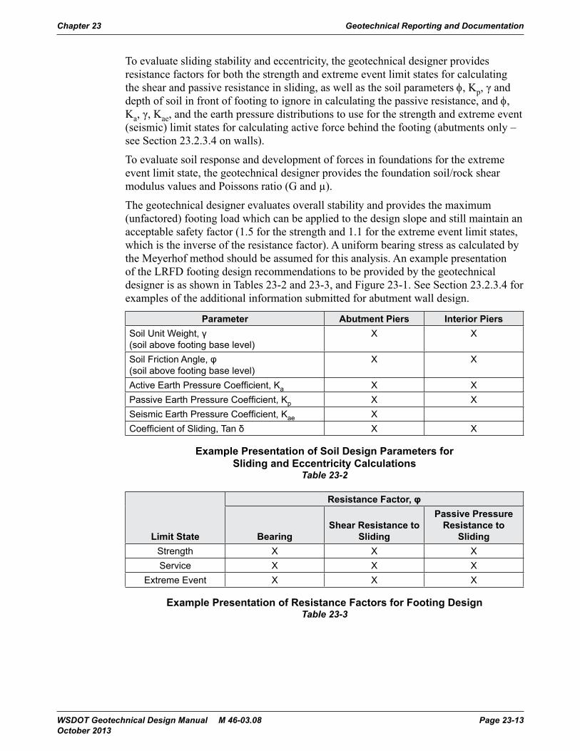
The geotechnical designer evaluates overall stability and provides the maximum (unfactored) footing load which can be applied to the design slope and still maintain an acceptable safety factor (1.5 for the strength and 1.1 for the extreme event limit states, which is the inverse of the resistance factor). A uniform bearing stress as calculated by the Meyerhof method should be assumed for this analysis. An example presentation of the LRFD footing design recommendations to be provided by the geotechnical designer is as shown in Tables 23-2 and 23-3, and Figure 23-1. See Section 23.2.3.4 for examples of the additional information submitted for abutment wall design.
Parameter Abutment Piers Interior PiersSoil Unit Weight, γ (soil above footing base level)
X X
Soil Friction Angle, φ (soil above footing base level)
X X
Active Earth Pressure Coefficient, Ka X XPassive Earth Pressure Coefficient, Kp X XSeismic Earth Pressure Coefficient, Kae XCoefficient of Sliding, Tan δ X X
Example Presentation of Soil Design Parameters for Sliding and Eccentricity Calculations
Table 23-2
Limit State
Resistance Factor, φ
BearingShear Resistance to
Sliding
Passive Pressure Resistance to
SlidingStrength X X XService X X X
Extreme Event X X X
Example Presentation of Resistance Factors for Footing DesignTable 23-3
Chapter 23 Geotechnical Reporting and Documentation
WSDOT Geotechnical Design Manual M 46-03.08 Page 23-13 October 2013
Geotechnical Reporting and Documentation Geotechnical Design Manual M 46-03 Chapter 23-16 December 2006
Geotechnical Reporting and Documentation
Effective Footing Width, B’
Bea
ring
Res
ista
nce,
qn
or q
serv
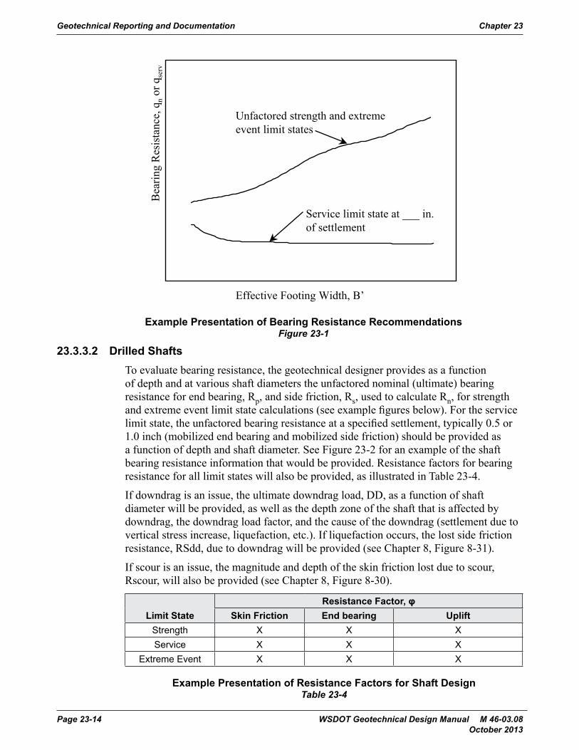
Service limit state at ___ in.of settlement
Unfactored strength and extremeevent limit states
Figure 23-1 Example presentation of bearing resistance recommendations.
23.2.3.2 Drilled ShaftsTo evaluate bearing resistance, the geotechnical designer provides as a function of depth and at various shaft diameters the unfactored nominal (ultimate) bearing resistance for end bearing, Rp, and side friction, Rs, used to calculate Rn, for strength and extreme event limit state calculations (see example figures below). For the service limit state, the unfactored bearing resistance at a specified settlement, typically 0.5 or 1.0 inch (mobilized end bearing and mobilized side friction) should be provided as a function of depth and shaft diameter. See Figure 23-2 for an example of the shaft bearing resistance information that would be provided. Resistance factors for bearing resistance for all limit states will also be provided, as illustrated in Table 23-4.
If downdrag is an issue, the ultimate downdrag load, DD, as a function of shaft diameter will be provided, as well as the depth zone of the shaft that is affected by downdrag, the downdrag load factor, and the cause of the downdrag (settlement due to vertical stress increase, liquefaction, etc.). If liquefaction occurs, the lost side friction resistance, RSdd, due to downdrag will be provided (see WSDOT GDM Chapter 8, Figure 8-31).
If scour is an issue, the magnitude and depth of the skin friction lost due to scour, Rscour, will also be provided (see WSDOT GDM Chapter 8, Figure 8-30).
Example Presentation of Bearing Resistance RecommendationsFigure 23-1
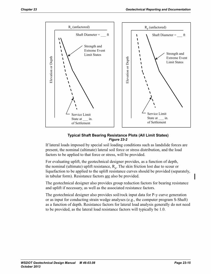
23.3.3.2 Drilled ShaftsTo evaluate bearing resistance, the geotechnical designer provides as a function of depth and at various shaft diameters the unfactored nominal (ultimate) bearing resistance for end bearing, Rp, and side friction, Rs, used to calculate Rn, for strength and extreme event limit state calculations (see example figures below). For the service limit state, the unfactored bearing resistance at a specified settlement, typically 0.5 or 1.0 inch (mobilized end bearing and mobilized side friction) should be provided as a function of depth and shaft diameter. See Figure 23-2 for an example of the shaft bearing resistance information that would be provided. Resistance factors for bearing resistance for all limit states will also be provided, as illustrated in Table 23-4.
If downdrag is an issue, the ultimate downdrag load, DD, as a function of shaft diameter will be provided, as well as the depth zone of the shaft that is affected by downdrag, the downdrag load factor, and the cause of the downdrag (settlement due to vertical stress increase, liquefaction, etc.). If liquefaction occurs, the lost side friction resistance, RSdd, due to downdrag will be provided (see Chapter 8, Figure 8-31).
If scour is an issue, the magnitude and depth of the skin friction lost due to scour, Rscour, will also be provided (see Chapter 8, Figure 8-30).
Limit StateResistance Factor, φ
Skin Friction End bearing UpliftStrength X X XService X X X
Extreme Event X X X
Example Presentation of Resistance Factors for Shaft DesignTable 23-4
Geotechnical Reporting and Documentation Chapter 23
Page 23-14 WSDOT Geotechnical Design Manual M 46-03.08 October 2013
Geotechnical Design Manual M 46-03 Geotechnical Reporting and Documentation December 2006 Chapter 23-17
Geotechnical Reporting and Documentation
Resistance Factor, ϕLimit State Skin Friction End bearing Uplift
Strength X X XService X X XExtreme Event X X X
Table 23-4 Example presentation of resistance factors for shaft design.
Elev
atio
n or
Dep
th
Rs (unfactored)
Elev
atio
n or
Dep
th
Rp (unfactored)
Strength andExtreme EventLimit States Strength and
Extreme EventLimit States
Service LimitState at ___ in.of Settlement
Service LimitState at ___ in.of Settlement
Shaft Diameter = ___ ft Shaft Diameter = ___ ft
Figure 23-2 Typical shaft bearing resistance plots (all limit states).
If lateral loads imposed by special soil loading conditions such as landslide forces are present, the nominal (ultimate) lateral soil force or stress distribution, and the load factors to be applied to that force or stress, will be provided.
For evaluating uplift, the geotechnical designer provides, as a function of depth, the nominal (ultimate) uplift resistance, Rn. The skin friction lost due to scour or liquefaction to be applied to the uplift resistance curves should be provided (separately, in tabular form). Resistance factors should also be provided.
Typical Shaft Bearing Resistance Plots (All Limit States)Figure 23-2
If lateral loads imposed by special soil loading conditions such as landslide forces are present, the nominal (ultimate) lateral soil force or stress distribution, and the load factors to be applied to that force or stress, will be provided.
For evaluating uplift, the geotechnical designer provides, as a function of depth, the nominal (ultimate) uplift resistance, Rn. The skin friction lost due to scour or liquefaction to be applied to the uplift resistance curves should be provided (separately, in tabular form). Resistance factors are also be provided.
The geotechnical designer also provides group reduction factors for bearing resistance and uplift if necessary, as well as the associated resistance factors.
The geotechnical designer also provides soil/rock input data for P-y curve generation or as input for conducting strain wedge analyses (e.g., the computer program S-Shaft) as a function of depth. Resistance factors for lateral load analysis generally do not need to be provided, as the lateral load resistance factors will typically be 1.0.
Chapter 23 Geotechnical Reporting and Documentation
WSDOT Geotechnical Design Manual M 46-03.08 Page 23-15 October 2013
23.3.3.3 PilesTo evaluate pile resistance, the geotechnical designer provides information regarding pile resistance using one of the following two approaches:
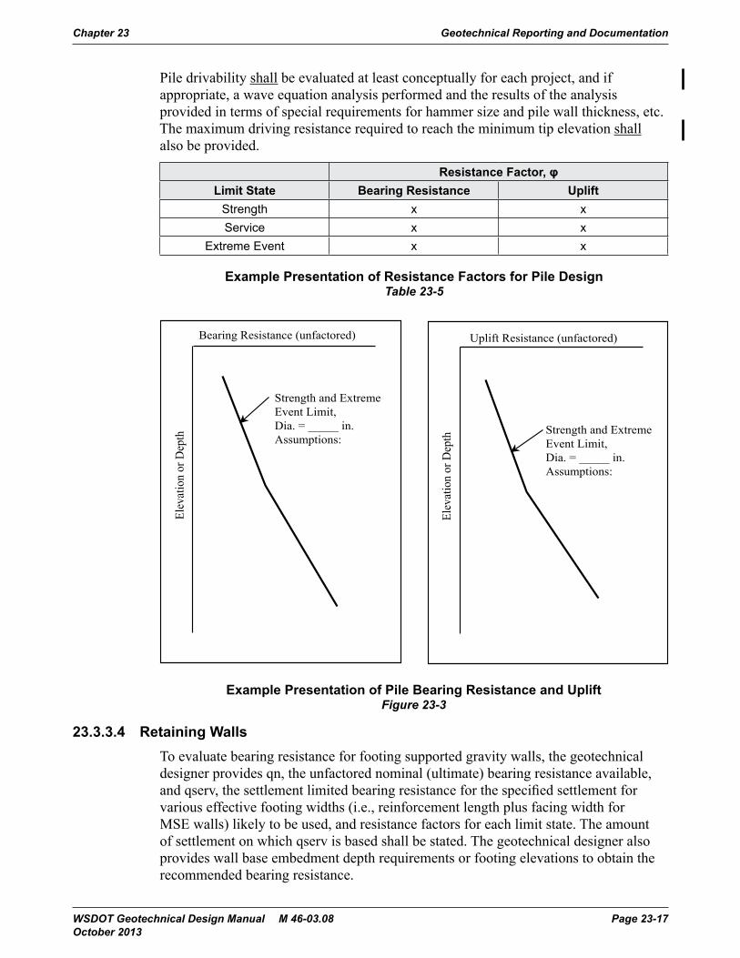
1. A plot of the unfactored nominal (ultimate) bearing resistance (Rn) as a function of depth for various pile types and sizes for strength and extreme event limit state calculations are provided. This design data would be used to determine the feasible ultimate pile resistance and the estimated depth for pile quantity determination. See Figure 23-3 for example of pile data presentation.
2. Only Rn and the estimated depth at which it could be obtained are provided for one or more selected pile types and sizes.
Resistance factors for bearing resistance for all limit states will also be provided (see Table 23-5 for an example).
If downdrag is an issue, the ultimate downdrag load, DD, as a function of pile diameter should be provided, as well as the depth zone of the pile that is affected by downdrag, the downdrag load factor, and the cause of the downdrag (settlement due to vertical stress increase, liquefaction, etc.). If liquefaction occurs, the lost side friction resistance, RSdd, due to downdrag should be provided (see Chapter 8, Figure 8-31).
If scour is an issue, the magnitude and depth of the skin friction lost due to scour, Rscour, should also be provided (see Chapter 8, Figure 8-30).
If lateral loads imposed by special soil loading conditions such as landslide forces are present, the ultimate lateral soil force or stress distribution, and the load factors to be applied to that force or stress, shall be be provided.
For evaluating uplift, the geotechnical designer shall provide, as a function of depth, the nominal (unfactored) uplift resistance, Rn. This is usually be provided as a function of depth, or as a single value for a given minimum tip elevation, depending on the project needs. The skin friction lost due to scour or liquefaction to be applied to the uplift resistance curves shall also be provided (separately, in tabular form). Resistance factors shall be also be provided for strength and extreme event limit states.
The geotechnical designer shall also provide group reduction factors for bearing resistance and uplift if necessary, as well as the associated resistance factors.
The geotechnical designer shall provide P-Y curve data as a function of depth. Resistance factors for lateral load analysis do not need to be provided, as the lateral load resistance factors will typically be 1.0.
Minimum tip elevations for the pile foundations shall be provided as appropriate. Minimum tip elevations shall be based on pile foundation settlement, and, if uplift loads are available, the depth required to provide adequate uplift resistance (see Section 8.12.6). Minimum pile tip elevations provided in the Geotechnical Report may need to be adjusted depending on the results of the lateral load and uplift load evaluation performed by the structural designer. If adjustment in the minimum tip elevations is necessary, or if the pile diameter needed is different than what was assumed by the geotechnical designer for pile resistance design, the geotechnical designer should be informed so that pile drivability, as discussed below, can be re-evaluated.
Geotechnical Reporting and Documentation Chapter 23
Page 23-16 WSDOT Geotechnical Design Manual M 46-03.08 October 2013
Pile drivability shall be evaluated at least conceptually for each project, and if appropriate, a wave equation analysis performed and the results of the analysis provided in terms of special requirements for hammer size and pile wall thickness, etc. The maximum driving resistance required to reach the minimum tip elevation shall also be provided.
Resistance Factor, φLimit State Bearing Resistance Uplift
Strength x xService x x
Extreme Event x x
Example Presentation of Resistance Factors for Pile DesignTable 23-5
Geotechnical Design Manual M 46-03 Geotechnical Reporting and Documentation December 2006 Chapter 23-19
Geotechnical Reporting and Documentation
Minimum tip elevations for the pile foundations should be provided as appropriate. Minimum tip elevations should be based on pile foundation settlement, and, if uplift loads are available, the depth required to provide adequate uplift resistance (see WSDOT GDM Section 8.12.6). Minimum pile tip elevations provided in the Geotechnical Report may need to be adjusted depending on the results of the lateral load and uplift load evaluation performed by the structural designer. If adjustment in the minimum tip elevations is necessary, or if the pile diameter needed is different than what was assumed by the geotechnical designer for pile resistance design, the geotechnical designer should be informed so that pile drivability, as discussed below, can be re-evaluated.
Pile drivability should be evaluated at least conceptually for each project, and if appropriate, a wave equation analysis performed and the results of the analysis provided in terms of special requirements for hammer size and pile wall thickness, etc. The maximum driving resistance required to reach the minimum tip elevation should also be provided.
Resistance Factor, ϕLimit State Bearing Resistance Uplift
Strength x xService x xExtreme Event x x
Table 23-5 Example presentation of resistance factors for pile design.
Elev
atio
n or
Dep
th
Bearing Resistance (unfactored)
Elev
atio
n or
Dep
th
Uplift Resistance (unfactored)
Strength and ExtremeEvent Limit,Dia. = _____ in.Assumptions:
Strength and ExtremeEvent Limit,Dia. = _____ in.Assumptions:
Figure 23-3 Example presentation of pile bearing resistance and uplift.Example Presentation of Pile Bearing Resistance and Uplift
Figure 23-3
23.3.3.4 Retaining WallsTo evaluate bearing resistance for footing supported gravity walls, the geotechnical designer provides qn, the unfactored nominal (ultimate) bearing resistance available, and qserv, the settlement limited bearing resistance for the specified settlement for various effective footing widths (i.e., reinforcement length plus facing width for MSE walls) likely to be used, and resistance factors for each limit state. The amount of settlement on which qserv is based shall be stated. The geotechnical designer also provides wall base embedment depth requirements or footing elevations to obtain the recommended bearing resistance.
Chapter 23 Geotechnical Reporting and Documentation
WSDOT Geotechnical Design Manual M 46-03.08 Page 23-17 October 2013
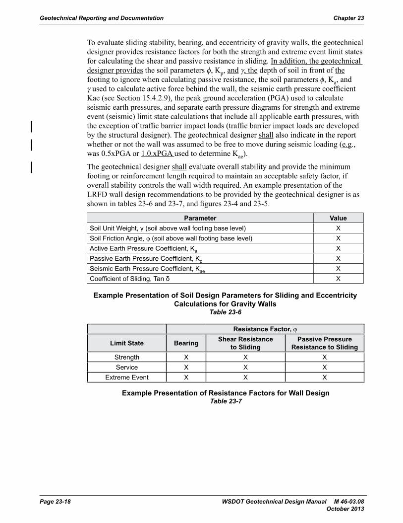
To evaluate sliding stability, bearing, and eccentricity of gravity walls, the geotechnical designer provides resistance factors for both the strength and extreme event limit states for calculating the shear and passive resistance in sliding. In addition, the geotechnical designer provides the soil parameters φ, Kp, and γ, the depth of soil in front of the footing to ignore when calculating passive resistance, the soil parameters φ, Ka, and γ used to calculate active force behind the wall, the seismic earth pressure coefficient Kae (see Section 15.4.2.9), the peak ground acceleration (PGA) used to calculate seismic earth pressures, and separate earth pressure diagrams for strength and extreme event (seismic) limit state calculations that include all applicable earth pressures, with the exception of traffic barrier impact loads (traffic barrier impact loads are developed by the structural designer). The geotechnical designer shall also indicate in the report whether or not the wall was assumed to be free to move during seismic loading (e.g., was 0.5xPGA or 1.0.xPGA used to determine Kae).
The geotechnical designer shall evaluate overall stability and provide the minimum footing or reinforcement length required to maintain an acceptable safety factor, if overall stability controls the wall width required. An example presentation of the LRFD wall design recommendations to be provided by the geotechnical designer is as shown in tables 23-6 and 23-7, and figures 23-4 and 23-5.
Parameter ValueSoil Unit Weight, ү (soil above wall footing base level) XSoil Friction Angle, φ (soil above wall footing base level) XActive Earth Pressure Coefficient, Ka XPassive Earth Pressure Coefficient, Kp XSeismic Earth Pressure Coefficient, Kae XCoefficient of Sliding, Tan δ X
Example Presentation of Soil Design Parameters for Sliding and Eccentricity Calculations for Gravity Walls
Table 23-6
Resistance Factor, ϕ
Limit State Bearing Shear Resistance to Sliding
Passive Pressure Resistance to Sliding
Strength X X XService X X X
Extreme Event X X X
Example Presentation of Resistance Factors for Wall DesignTable 23-7
Geotechnical Reporting and Documentation Chapter 23
Page 23-18 WSDOT Geotechnical Design Manual M 46-03.08 October 2013
Geotechnical Design Manual M 46-03 Geotechnical Reporting and Documentation December 2006 Chapter 23-21
Geotechnical Reporting and Documentation
Resistance Factor, ϕ
Limit State BearingShear Resistance to
SlidingPassive Pressure
Resistance to SlidingStrength X X XService X X XExtreme Event X X X
Table 23-7 Example presentation of resistance factors for wall design.
Effective Footing Width, B’
Bea
ring
Res
ista
nce,
qn
or q
serv
Service limit state at ___ in.of settlement
Unfactored strength and extremeevent limit states
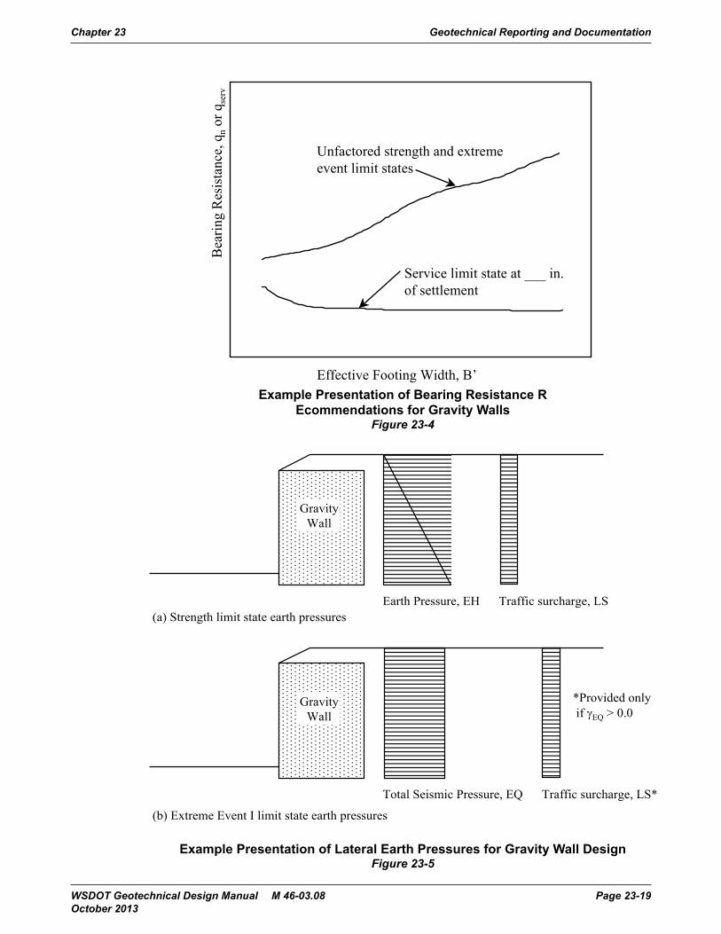
Figure 23-4 Example presentation of bearing resistance recommendations for gravity walls.
Example Presentation of Bearing Resistance R Ecommendations for Gravity Walls
Figure 23-4
Geotechnical Reporting and Documentation Geotechnical Design Manual M 46-03 Chapter 23-22 December 2006
Geotechnical Reporting and Documentation
Earth Pressure, EH Traffic surcharge, LS
GravityWall
(a) Strength limit state earth pressures
Total Seismic Pressure, EQ Traffic surcharge, LS*
GravityWall
(b) Extreme Event I limit state earth pressures
*Provided onlyif EQ > 0.0
Figure 23-5 Example presentation of lateral earth pressures for gravity wall design.
For non-proprietary MSE walls, the spacing, strength, and length of soil reinforcement should also be provided, as well as the applicable resistance factors.
For non-gravity cantilever walls and anchored walls, ultimate bearing resistance of the soldier piles or drilled shafts as a function of depth (see WSDOT GDM Section 23.2.3.2, and Figure 23-2), the lateral earth pressure distribution (active and passive), the minimum embedment depth required for overall stability, and the no load zone dimensions, ultimate anchor resistance for anchored walls, and the associated resistance factors should be provided. Table 23-7 and Figure 23-6 provide an example presentation of earth pressure diagrams for nongravity cantilever and anchored walls to be provided by the geotechnical designer.
Example Presentation of Lateral Earth Pressures for Gravity Wall DesignFigure 23-5
Chapter 23 Geotechnical Reporting and Documentation
WSDOT Geotechnical Design Manual M 46-03.08 Page 23-19 October 2013
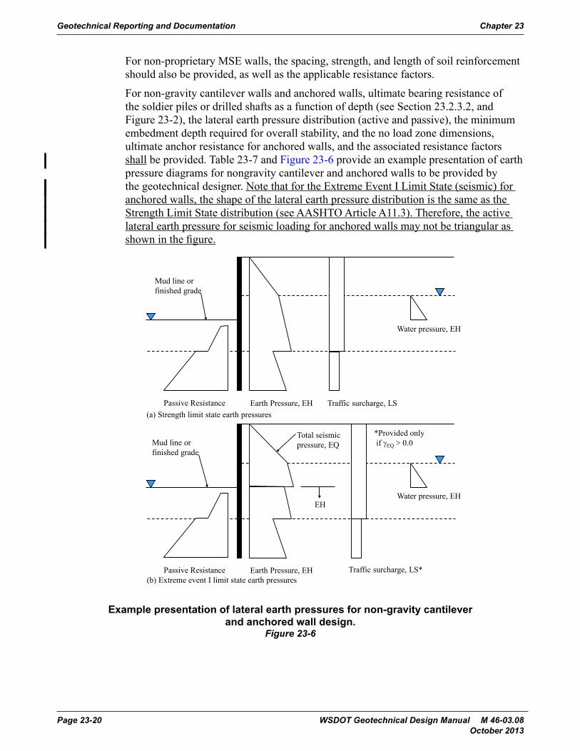
For non-proprietary MSE walls, the spacing, strength, and length of soil reinforcement should also be provided, as well as the applicable resistance factors.
For non-gravity cantilever walls and anchored walls, ultimate bearing resistance of the soldier piles or drilled shafts as a function of depth (see Section 23.2.3.2, and Figure 23-2), the lateral earth pressure distribution (active and passive), the minimum embedment depth required for overall stability, and the no load zone dimensions, ultimate anchor resistance for anchored walls, and the associated resistance factors shall be provided. Table 23-7 and Figure 23-6 provide an example presentation of earth pressure diagrams for nongravity cantilever and anchored walls to be provided by the geotechnical designer. Note that for the Extreme Event I Limit State (seismic) for anchored walls, the shape of the lateral earth pressure distribution is the same as the Strength Limit State distribution (see AASHTO Article A11.3). Therefore, the active lateral earth pressure for seismic loading for anchored walls may not be triangular as shown in the figure.
.
Passive Resistance Earth Pressure, EH Traffic surcharge, LS
Water pressure, EH
Passive Resistance Earth Pressure, EH Traffic surcharge, LS*
Water pressure, EH
Total seismic pressure, EQ
EH
*Provided onlyif γEQ > 0.0
(a) Strength limit state earth pressures
(b) Extreme event I limit state earth pressures
Mud line or finished grade
Mud line or finished grade
Example presentation of lateral earth pressures for non-gravity cantilever and anchored wall design.
Figure 23-6
Geotechnical Reporting and Documentation Chapter 23
Page 23-20 WSDOT Geotechnical Design Manual M 46-03.08 October 2013
23.4 Information to Be Provided in the Geotechnical Design FileDocumentation that provides details of the basis of recommendations made in the geotechnical report or memorandum is critical not only for review by senior staff, but also for addressing future questions that may come up regarding the basis of the design, to address changes that may occur after the geotechnical design is completed, to address questions regarding the design during construction to address problems or claims, and for background for developing future projects in the same location, such as bridge or fill widenings. Since the engineer who does the original design may not necessarily be the one who deals with any of these future activities, the documentation must be clear and concise, and easy and logical to follow. Anyone who must look at the calculations and related documentation should not have to go to the original designer to understand what was done.
The project documentation should be consistent with FHWA guidelines, as mentioned at the beginning of this chapter, and shall be consistent with the requirements specified in this GDM. Details regarding what this project documentation should contain are provided in the sections that follow.
23.4.1 Documentation for Conceptual Level Geotechnical DesignDocument sources of information (including the date) used for the conceptual evaluation. Typical sources include final records, as-built bridge or other structure layouts, existing test hole logs, geologic maps, previous or current geologic reconnaissance results, etc.
If a geologic reconnaissance was or is conducted, the details of that review, including any photos taken that are necessary to illustrate the conditions observed shall be included in this documentation. For structures, provide a description of the foundation support used for the existing structure, including design bearing capacity, if known, and any foundation capacity records such as pile driving logs, load test results, etc. From the final contract records, summarize any known construction problems encountered when building the existing structure. Examples include over-excavation depth and extent, and why it was needed, seepage observed in cuts and excavations, dewatering problems, difficult digging, including obstructions encountered during excavation, obstructions encountered during foundation installation (e.g., for piles or shafts), slope instability during construction, changed conditions or change orders involving the geotechnical features of the project, and anything else that would affect the geotechnical aspects of the project.
For any geotechnical recommendations made, summarize the logic and justification for those recommendations. If the recommendations are based on geotechnical engineering experience and judgment, describe what specific information led to the recommendation(s) made.
23.4.2 Documentation for Final Geotechnical DesignIn addition to the information described in Section 23.4.1, the following information shall be documented in the project geotechnical file (or design calculation package submitted by a consultant, contractor, or design builder for WSDOT review as specified in Section 23.5):
Chapter 23 Geotechnical Reporting and Documentation
WSDOT Geotechnical Design Manual M 46-03.08 Page 23-21 October 2013
1. List or describe all given information and assumptions used, as well as the source of that information. For all calculations, an idealized design cross-section that shows the design element (e.g., wall, footing, pile foundation, buttress, etc.) located in context to the existing and proposed ground lines, and the foundation soil/rock shall be provided. This idealized cross-section should show the soil/rock properties used for design, the soil/rock layer descriptions and thicknesses, the water table location, the existing and proposed ground line, and any other pertinent information. An example design cross-section for a deep foundation is shown in Appendix 23-B. For slope stability, the soil/rock properties used for the design should be shown (handwritten, if necessary) on the computer generated output cross-section.
2. Additional information and/or a narrative shall also be provided which describes the basis for the design soil/rock properties used. The additional details and requirements in Chapter 5 as well as other GDM chapters, applicable to the specific situation, regarding assessment and determination of geotechnical design parameters shall be followed when developing and documenting justification of the selected design parameters. If the properties are from laboratory tests, state where the test results, and the analysis of those test results, can be found in the final geotechnical design documentation and how those test results apply to the specific site conditions and strata encountered, including consideration of site geological history. If using correlations to SPT or cone data, or other measurements, state which correlations were used, the range of applicability of the correlation to the available measurements, the potential uncertainty in the estimated property value due to the use of that correlation, and any corrections to the data made. If using back-analysis based on measurable performance of geotechnical features at the site or near the site in similar geologic conditions and stratigraphy, provide the complete analyses and any assumptions used that are necessary to reduce the number of degrees of freedom in the design model used. When more than one of these approaches to defining design parameters is available and used, the consistency of the results shall be assessed, and the logic used to make the final selection of design parameters obtained from these analyses shall be provided in the documentation. The uncertainty in the design parameters shall also be considered when selecting geotechnical parameters for design. How this uncertainty is addressed shall be documented (e.g., conservative selection of the design parameters or increased overall level of safety used in the design, or both).
3. Identify what is to be determined from these calculations (i.e., what is the objective?). For example, objectives could include foundation bearing resistance, foundation or fill settlement (differential and total), time rate of settlement, the cut or fill slope required, the size of the stabilizing berm required, etc.
4. The design method(s) used shall also be clearly identified for each set of calculations, including any assumptions used to simplify the calculations, if that was done, or to determine input values for variables in the design equation. Write down equation(s) used and meaning of terms used in equation(s), or reference where equation(s) used and/or meaning of terms were obtained. Attach a copy of all curves or tables used in making the calculations and their source, or appropriately reference those tables or figures. Write down or summarize all steps needed to solve the equations and to obtain the desired solution.
Geotechnical Reporting and Documentation Chapter 23
Page 23-22 WSDOT Geotechnical Design Manual M 46-03.08 October 2013
5. Identify the load and resistance factors, or safety factors, used for the design. If it is necessary to diverge from the level of safety requirements in the GDM and referenced manuals (e.g., AASHTO), subject to the approval of the State Geotechnical Engineer, identify, and provide justification for, the level of safety used for the design (e.g., load and resistance factors, or safety factors), considering the bias and uncertainty in the design method(s) used, and the uncertainty in the geotechnical design parameters selected for the design.
6. If using computer spreadsheets, provide detailed calculations for one example to demonstrate the basis of the spreadsheet and that the spreadsheet is providing accurate results. Hand calculations are not required for well proven, well documented, and stable programs such as XSTABL or the wave equation. Detailed example calculations that illustrate the basis of the spreadsheet are important for engineering review purposes and for future reference if someone needs to get into the calculations at some time in the future. A computer spreadsheet in itself is not a substitute for that information.
7. Highlight the solutions that form the basis of the engineering recommendations to be found in the project geotechnical report so that they are easy to find. Be sure to write down which locations or piers where the calculations and their results are applicable.
8. Provide a results summary, including a sketch of the final design, if appropriate.
Each set of calculations shall be signed and dated, and the reviewer shall also sign and date the calculations. The name of the designer and reviewer shall also be printed below the signature, to clearly identify these individuals, if their names do not appear on the seals. Calculations and documents shall be sealed in accordance with State Law. Consecutive page numbers should be provided for each set of calculations, and the calculation page numbers for which the stamps and signatures are applicable should be indicated below or beside the stamps.
These requirements also apply to preliminary designs or portions of a project geotechnical design submitted for specific project elements.
23.4.3 Geotechnical File ContentsThe geotechnical project file(s) should contain the information necessary for future users of the file to understand the historical geotechnical data available, the scope of the project, the dimensions and locations of the project features understood at the time the geotechnical design was completed, the geotechnical investigation plan and the logic used to develop that plan, the relationship of that plan to what was requested by the Region, Bridge Office, Urban Corridors Office, Washington State Ferries Office, or other office, the geotechnical design conducted, what was recommended, and when and to whom it was recommended. Two types of project files should be maintained: the geotechnical design file(s), and the construction support file(s).
The geotechnical design file should contain the following information (in addition to the final geotechnical report):• Historical project geotechnical and as-built data (see Section 23.3.1)• Geotechnical investigation plan development documents• Geologic reconnaissance results
Chapter 23 Geotechnical Reporting and Documentation
WSDOT Geotechnical Design Manual M 46-03.08 Page 23-23 October 2013
• Critical end area plots, cross-sections, structure layouts, etc., that demonstrate the scope of the project and project feature geometry as understood at the time of the final design, if such data is not contained in the geotechnical report
• Information that illustrates design constraints, such as right-of-way location, location of critical utilities, location and type of adjacent facilities that could be affected by the design, etc.
• Boring log field notes• Boring logs• Lab transmittals• Lab data, including rock core photos and records• Field instrumentation measurements• Final calculations only, unless preliminary calculations are needed to show design
development• Final wave equation runs for pile foundation constructability evaluation• Key photos (must be identified as to the subject and locations), including CD with
photo files• Key correspondence (including e-mail) that tracks the development of the project –
this does not include correspondence that is focused on coordination activities
The geotechnical construction file should contain the following information:• Change order correspondence and calculations• Claim correspondence and data• Construction submittal reviews (retain temporarily only, until it is clear that there
will be no construction claims)• Photos (must be identified as to the subject and locations), including CD with
photo files• CAPWAP reports• Final wave equation runs and pile driving criteria development• CSL reports
23.5 Consultant Geotechnical Reports and Documentation Produced on Behalf of WSDOT
Geotechnical reports and documentation produced by geotechnical consultants, including geotechnical work conducted in support of Cost Reduction Incentive proposals (CRIP’s), shoring submittals, and design-build projects, shall be subject to the same reporting and documentation requirements as those produced by WSDOT staff, as described in Sections 23.2 and 23.3. The detailed analyses and/or calculations produced by the consultant in support of the geotechnical report development shall be provided to the State.
Geotechnical Reporting and Documentation Chapter 23
Page 23-24 WSDOT Geotechnical Design Manual M 46-03.08 October 2013
23.6 Summary of Geotechnical ConditionsThe “Summary of Geotechnical Conditions” is generally a 1 to 2 page document that briefly summarizes the subsurface and ground water conditions for key areas of the project where foundations, cuts, fills, etc., are to be constructed. This document also describes the impact of these subsurface conditions on the construction of these foundations, cuts, fills, etc., to provide a common basis for interpretation of the conditions and bidding. A Summary of Geotechnical Conditions is primarily used for design-bid-build projects, as the Geotechnical Baseline Report (Chapter 22) serves the functions described above for design-build projects.
A Summary of Geotechnical Conditions is mandatory for all projects that contain bridges, walls, tunnels, unstable slope repairs, and significant earth work. The Summary of Geotechnical Conditions should specifically contain the following information:
1. Describe subsurface conditions in plain English. Avoid use of jargon and/or nomenclature that contactors will not understand. Identify depths/thicknesses of the soil or rock strata and their moisture state and density condition. Identify the depth/elevation of groundwater and state its nature (e.g. perched, regional, artesian, etc.). If multiple readings over time were obtained, identify dates and depths measured, or as a minimum provide the range of depths measured and the dates the highest and lowest water level readings were obtained. Also briefly describe the method used to obtain the water level (e.g., open standpipe, sealed piezometer, including what soil/rock unit the piezometer was sealed in, etc.). Refer to the boring logs for detailed information. If referring to an anomalous soil, rock or groundwater condition, refer to boring log designation where the anomaly was encountered. Caution should also be exercised when describing strata depths. If depths/thicknesses are based on only one boring, simply refer to the boring log for that information. Comments regarding the potential for variability in the strata thicknesses may be appropriate here. Also note that detailed soil/rock descriptions are not necessary if those conditions will not impact the contractor’s construction activities. For example, for fills or walls placed on footings, detailed information is only needed that would support later discussion in this document regarding the workability of the surficial soils, as well as the potential for settlement or instability and their effect on construction.
2. For each structure, if necessary, state the impact the soil, rock or groundwater condition may (will) have on construction. Where feasible, refer to boring log(s) or data that provide the indication of risk. Be sure to mention the potential of risk for: • Caving ground• Slope instability due to temporary excavation, or as a result of a project element
(e.g. buttress, tieback wall, soil nail cuts)• Settlement and its effect on how a particular structure or fill needs to be built• Potential geotechnical impact of the construction of some elements on the
performance of adjacent elements that are, or are not, a part of the construction contract (e.g., ground improvement performed at the toe of a wall could cause movement of that wall)
• Groundwater flow and control, if anticipated, in construction excavations
Chapter 23 Geotechnical Reporting and Documentation
WSDOT Geotechnical Design Manual M 46-03.08 Page 23-25 October 2013
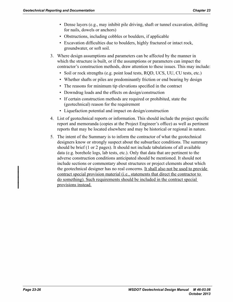
• Dense layers (e.g., may inhibit pile driving, shaft or tunnel excavation, drilling for nails, dowels or anchors)
• Obstructions, including cobbles or boulders, if applicable• Excavation difficulties due to boulders, highly fractured or intact rock,
groundwater, or soft soil.
3. Where design assumptions and parameters can be affected by the manner in which the structure is built, or if the assumptions or parameters can impact the contractor’s construction methods, draw attention to these issues. This may include:• Soil or rock strengths (e.g. point load tests, RQD, UCS, UU, CU tests, etc.)• Whether shafts or piles are predominantly friction or end bearing by design• The reasons for minimum tip elevations specified in the contract• Downdrag loads and the effects on design/construction• If certain construction methods are required or prohibited, state the
(geotechnical) reason for the requirement• Liquefaction potential and impact on design/construction
4. List of geotechnical reports or information. This should include the project specific report and memoranda (copies at the Project Engineer’s office) as well as pertinent reports that may be located elsewhere and may be historical or regional in nature.
5. The intent of the Summary is to inform the contractor of what the geotechnical designers know or strongly suspect about the subsurface conditions. The summary should be brief (1 or 2 pages). It should not include tabulations of all available data (e.g. borehole logs, lab tests, etc.). Only that data that are pertinent to the adverse construction conditions anticipated should be mentioned. It should not include sections or commentary about structures or project elements about which the geotechnical designer has no real concerns. It shall also not be used to provide contract special provision material (i.e., statements that direct the contractor to do something). Such requirements should be included in the contract special provisions instead.
Geotechnical Reporting and Documentation Chapter 23
Page 23-26 WSDOT Geotechnical Design Manual M 46-03.08 October 2013
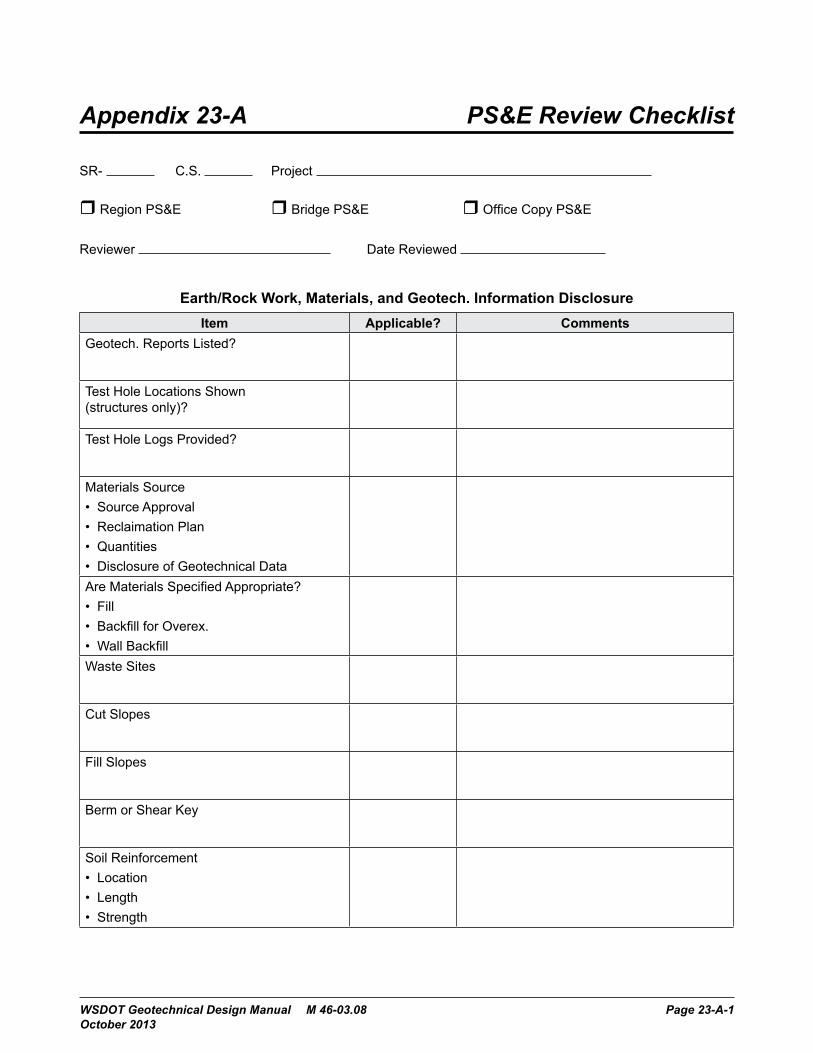
Appendix 23-A PS&E Review Checklist
SR- C.S. Project
Region PS&E Bridge PS&E Office Copy PS&E
Reviewer Date Reviewed
Earth/Rock Work, Materials, and Geotech. Information DisclosureItem Applicable? Comments
Geotech. Reports Listed?
Test Hole Locations Shown (structures only)?
Test Hole Logs Provided?
Materials Source• Source Approval• Reclaimation Plan• Quantities• Disclosure of Geotechnical DataAre Materials Specified Appropriate?• Fill• Backfill for Overex.• Wall BackfillWaste Sites
Cut Slopes
Fill Slopes
Berm or Shear Key
Soil Reinforcement• Location• Length• Strength
WSDOT Geotechnical Design Manual M 46-03.08 Page 23-A-1 October 2013

Earth/Rock Work, Materials, and Geotech. Information Disclosure, Cont.Item Applicable? Comments
Unsuitable Excavation
Ground Modification• Wick Drains• Stone Columns• Vibrocompaction, compaction grouting,
etc.• Advisory Specifications?Settlement Mitigation• Surcharges• Fill Overbuild• Light Weight Fill• Preload Settlement PeriodRock Cuts and Blasting• Slopes• Special Provisions - Blasting• Rock ReinforcementSlope Drainage Features
PS&E Review Checklist Appendix 23-A
Page 23-A-2 WSDOT Geotechnical Design Manual M 46-03.08 October 2013

Bridges and TunnelsItem Applicable? Comments
Spread Footings• Elevations/Embed.• Bearing Capacity• Seals• Overexcavation Requirements• Soil Densification Requirements• Advisory Specifications?Piles• Quantities• Minimum Tip Elevations• Capacity• Pile Type and Size• Hammer Requirements• Special Pile Tips• Special Material Requirements• Pile Spacing• Advisory Specifications?Shafts• Tip Elevations• Shaft Diameter• Casing Requirements• Special Location Requirements for Tip• Shaft Spacing• Advisory Specifications?Seismic Design• Acceleration Coefficient• Liquefaction Mitigation Requirements• Special Design requirementsAbutment and Endslope Design
Appendix 23-A PS&E Review Checklist
WSDOT Geotechnical Design Manual M 46-03.08 Page 23-A-3 October 2013

Retaining WallsSR- C.S. Project
Item Applicable? CommentsWall Number(s)
Wall Types Allowed
Facing Types?
External Stability• Wall Base Embedment or Elevation• Bearing Capacity• Min. Wall Width• Pile Support Requirements• Shaft Support Requirements• Overexcavation or Soil Densification
Requirements• Surcharge Conditions are as Assumed?• Slope Below Wall is as Assumed?• Advisory Specifications?Internal Stability• Soil Reinforcement Strength and Spacing
Requirements• Reinforcement Type• No Load Zone Requirements• Soil Design ParametersWall Drainage Features
Wall Backfill Type
Wall Quantities
Specifications Appropriate for Wall?• Preapproved?• Construction Tolerances?
Copy This Page to Wall Database Manager
PS&E Review Checklist Appendix 23-A
Page 23-A-4 WSDOT Geotechnical Design Manual M 46-03.08 October 2013
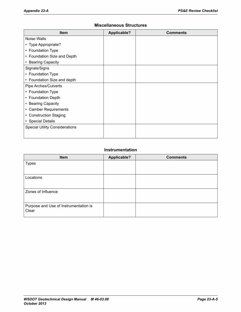
Miscellaneous StructuresItem Applicable? Comments
Noise Walls• Type Appropriate?• Foundation Type• Foundation Size and Depth• Bearing CapacitySignals/Signs• Foundation Type• Foundation Size and depthPipe Arches/Culverts• Foundation Type• Foundation Depth• Bearing Capacity• Camber Requirements• Construction Staging• Special DetailsSpecial Utility Considerations
InstrumentationItem Applicable? Comments
Types
Locations
Zones of Influence
Purpose and Use of Instrumentation is Clear
Appendix 23-A PS&E Review Checklist
WSDOT Geotechnical Design Manual M 46-03.08 Page 23-A-5 October 2013
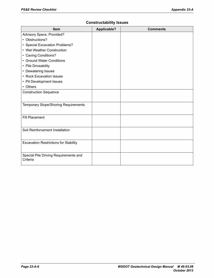
Constructability IssuesItem Applicable? Comments
Advisory Specs. Provided?• Obstructions?• Special Excavation Problems?• Wet Weather Construction• Caving Conditions?• Ground Water Conditions• Pile Driveability• Dewatering Issues• Rock Excavation Issues• Pit Development Issues• OthersConstruction Sequence
Temporary Slope/Shoring Requirements
Fill Placement
Soil Reinforcement Installation
Excavation Restrictions for Stability
Special Pile Driving Requirements and Criteria
PS&E Review Checklist Appendix 23-A
Page 23-A-6 WSDOT Geotechnical Design Manual M 46-03.08 October 2013
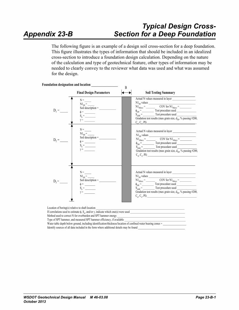
Typical Design Cross- Appendix 23-B Section for a Deep Foundation
The following figure is an example of a design soil cross-section for a deep foundation. This figure illustrates the types of information that should be included in an idealized cross-section to introduce a foundation design calculation. Depending on the nature of the calculation and type of geotechnical feature, other types of information may be needed to clearly convey to the reviewer what data was used and what was assumed for the design.
Geotechnical D
esign Manual
M 46-03
G
eotechnical Reporting and D
ocumentation
Decem
ber 2006
Chapter 23-37
Appendix 23-B
Typical D
esign Cross-Section
for a D
eep Foundation
The following figure is an exam
ple of a design soil cross-section for a deep foundation. This figure illustrates the types of inform
ation that should be included in an idealized cross-section to introduce a foundation design calculation. D
epending on the nature of the calculation and type of geotechnical feature, other types of inform
ation may be needed to clearly convey to the review
er what data w
as used and w
hat was assum
ed for the design.
Location of boring(s) relative to shaft location ____________________________________________________________________If correlations used to estimate , Su, and/or , indicate which one(s) were used __________________________________________Method used to correct N for overburden and SPT hammer energy ____________________________________________________Type of SPT hammer, and measured SPT hammer efficiency, if available _______________________________________________Water table depth below ground, including identification/thickness/location of confined water bearing zones = __________________Identify sources of all data included in the form where additional details may be found ____________________________________
B
D1 = _____
D2 = _____
D3 = _____
N = _____N160 = _____Soil description = _____________ = ________Su = ________ = ________
Final Design Parameters Soil Testing SummaryActual N values measured in layer __________________N160 values ____________________________________N160ave = _______ COV for N160ave = _________lab = _________ Test procedure used _______________Sulab = _________ Test procedure used _______________Gradation test results (max grain size, d50, % passing #200,Cu, Cc, PI) ______________________________________
N = _____N160 = _____Soil description = _____________ = ________Su = ________ = ________
N = _____N160 = _____Soil description = _____________ = ________Su = ________ = ________
Foundation designation and location _________________
Actual N values measured in layer __________________N160 values ____________________________________N160ave = _______ COV for N160ave = _________lab = _________ Test procedure used _______________Sulab = _________ Test procedure used _______________Gradation test results (max grain size, d50, % passing #200,Cu, Cc, PI) ______________________________________
Actual N values measured in layer __________________N160 values ____________________________________N160ave = _______ COV for N160ave = _________lab = _________ Test procedure used _______________Sulab = _________ Test procedure used _______________Gradation test results (max grain size, d50, % passing #200,Cu, Cc, PI) ______________________________________
WSDOT Geotechnical Design Manual M 46-03.08 Page 23-B-1 October 2013

Typical Design Cross-Section for a Deep Foundation Appendix 23-B
Page 23-B-2 WSDOT Geotechnical Design Manual M 46-03.08 October 2013

![Geotechnical Investigation and Reporting · Geotechnical Investigation and Reporting Guidelines for Development Applications in the City of Ottawa [PDF 163 KB] Introduction . 1.1](https://img.pdfslide.us/doc/110x75/5e89524c251d2224c604275a/geotechnical-investigation-and-reporting-geotechnical-investigation-and-reporting.jpg)