Embed Size (px)
Citation preview
21Stability of Slopes
21.1 Introduction
21.2 Factors to Consider
21.3 Analytical Approaches General • Circular Failure Surfaces • Chart Solutions for Homogeneous Slopes • Irregular and Planar Failure Surfaces • Earthquake Forces
21.4 Treatments to Improve StabilityGeneral Concepts • Changing Slope Geometry • Surface Water Control • Internal Seepage Control • Increased Strength • Side-Hill Fills • Retention • Embankments
21.5 Investigation and MonitoringExploration • Instrumentation and Monitoring
21.1 Introduction
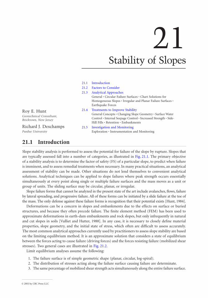
Slope stability analysis is performed to assess the potential for failure of the slope by rupture. Slopes thatare typically assessed fall into a number of categories, as illustrated in Fig. 21.1. The primary objectiveof a stability analysis is to determine the factor of safety (FS) of a particular slope, to predict when failureis imminent, and to assess remedial treatments when necessary. In many practical situations, an analyticalassessment of stability can be made. Other situations do not lend themselves to convenient analyticalsolutions. Analytical techniques can be applied to slope failures where peak strength occurs essentiallysimultaneously at every point along single or multiple failure surfaces and the mass moves as a unit orgroup of units. The sliding surface may be circular, planar, or irregular.
Slope failure forms that cannot be analyzed in the present state of the art include avalanches, flows, failureby lateral spreading, and progressive failure. All of these forms can be initiated by a slide failure at the toe ofthe mass. The only defense against these failure forms is recognition that their potential exists [Hunt, 1984].
Deformations can be a concern in slopes and embankments due to the effects on surface or buriedstructures, and because they often precede failure. The finite element method (FEM) has been used toapproximate deformations in earth-dam embankments and rock slopes, but only infrequently in naturaland cut slopes in soils [Vulliet and Hutter, 1988]. In any case, it is necessary to closely define materialproperties, slope geometry, and the initial state of stress, which often are difficult to assess accurately.The most common analytical approaches currently used by practitioners to assess slope stability are basedon the limiting equilibrium method. It is an approximate solution that considers a state of equilibriumbetween the forces acting to cause failure (driving forces) and the forces resisting failure (mobilized shearstresses). Two general cases are illustrated in Fig. 21.2.
Limit equilibrium analyses assume the following:
1. The failure surface is of simple geometric shape (planar, circular, log-spiral).2. The distribution of stresses acting along the failure surface causing failure are determinate.3. The same percentage of mobilized shear strength acts simultaneously along the entire failure surface.
Roy E. HuntGeotechnical Consultant, Bricktown, New Jersey
Richard J. DeschampsPurdue University
© 2003 by CRC Press LLC
21
-2
The Civil Engineering Handbook, Second Edition
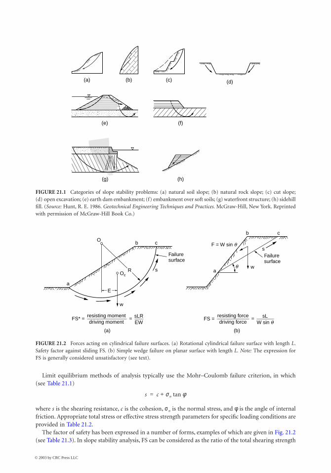
Limit equilibrium methods of analysis typically use the Mohr–Coulomb failure criterion, in which(see Table 21.1)
where s is the shearing resistance, c is the cohesion, sn is the normal stress, and f is the angle of internalfriction. Appropriate total stress or effective stress strength parameters for specific loading conditions areprovided in Table 21.2.
The factor of safety has been expressed in a number of forms, examples of which are given in Fig. 21.2(see Table 21.3). In slope stability analysis, FS can be considered as the ratio of the total shearing strength
FIGURE 21.1 Categories of slope stability problems: (a) natural soil slope; (b) natural rock slope; (c) cut slope;(d) open excavation; (e) earth dam embankment; (f) embankment over soft soils; (g) waterfront structure; (h) sidehillfill. (Source: Hunt, R. E. 1986. Geotechnical Engineering Techniques and Practices. McGraw-Hill, New York. Reprintedwith permission of McGraw-Hill Book Co.)
FIGURE 21.2 Forces acting on cylindrical failure surfaces. (a) Rotational cylindrical failure surface with length L.Safety factor against sliding FS. (b) Simple wedge failure on planar surface with length L. Note: The expression forFS is generally considered unsatisfactory (see text).
(b)
(e) (f)
(g) (h)
(c) (d)(a)
Ob
a
c
c
s
b
wa
F = W sin q
qsR
(a) (b)
E
Oc
w
Failuresurface
Failuresurface
FS* = = resisting momentdriving moment
sLREW
FS = = resisting forcedriving force
sLW sin q
s c sn ftan+=
© 2003 by CRC Press LLC
Stability of Slopes
21
-3
available along the sliding surface to the total shearing stresses required to maintain limiting equilibrium,given as
where L is the length of the failure surface, N is the normal force on the assumed failure surface, cm isthe mobilized cohesion at equilibrium, fm is the mobilized friction angle at equilibrium, and c/cm = f /fm.
21.2 Factors to Consider
Selection of the proper method to be applied to the analysis of a slope problem requires considerationof a number of factors. Specific details can be found in the referenced works.
• Type of slope to be analyzed, such as natural or cut slope in soil [Bjerrum, 1973; Patton andHendron, 1974; Brand, 1982; Leonards, 1979, 1982] or rock [Deere, 1976], earth-dam embank-ments [Lowe, 1967], embankments over soft ground [Chirapuntu and Duncan, 1976; Ladd, 1991],or sidehill fills.
TABLE 21.1 Field Conditions and Strength Parameters Acting at Failure
Material Field Conditions Strength Parametera
Cohesionless sands Dry f (i = f)Submerged slope f (i = f¢)Slope seepage with top flow line coincident
with and parallel to slow surfacef (i = f¢/2)
Clays (except stiff fissured clays and clay shales)
Undrained conditionsDrained conditions
Su (f = 0)c¢fb
Stiff fissured clays and clay shalesand existing failure surfaces
Without slope seepageWith slope seepage
f¢r (i ª f¢r)b
f¢r (i ª f¢r/2b)Cohesive mixtures Undrained conditions cu , fu
Drained conditions c¢, fb Rock joints Clean surfaces f or f + j c
With fillings c¢, f, or f¢Clean but irregular surfaces after failure ft + jc
Source: Hunt, R. E. 1986. Geotechnical Engineering Techniques and Practices. McGraw-Hill, New York.Reprinted with permission of McGraw-Hill Book Co.a i = stable slope angle.b Pore-water pressures: reduce frictional resistance in accordance with (N – U) tan f.c j = angle of asperities.
TABLE 21.2 Total versus Effective Stress Analysis
Condition Preferred Method Comment
Stability at intermediate times analysis with estimated pore pressures
Actual pore pressures must be field-checked.
End of construction; partiallysaturated soil; constructionperiod short compared to soilconsolidation time
Either method: from CU tests, or plus
estimated pore pressures
analysis permits check during construction using actual pore pressures
End of construction; saturated soil; construction period short compared to consolidation time
Total stress or su analysis with f = 0 andc = su
analysis permits check during construction using actual pore pressures
Long-term stability analysis with pore pressures given by equilibrium ground-water conditions
Stability depends on amount of water-table rise and pore-pressure increase
Source: After Lambe, T. W., and Whitman, R. V. 1969. Soil Mechanics. John Wiley & Sons, New York.
c f,
cu fu, c f,c f,
c f,
c f,
FS cL N ftan+cmL N fmtan+------------------------------------=
© 2003 by CRC Press LLC
21
-4 The Civil Engineering Handbook, Second Edition
• Location, orientation, and shape of a potential or existing failure surface which is controlled bymaterial type and structural features. The shape of the rupture zone can have single or multiplesurfaces, and can be composed of single or multiple wedges. Failure surfaces can be planar,cylindrical or log-spiral, or irregular.
• Material distribution (stratigraphy) within and beneath the slope, divided generally into homo-geneous zones wherein the properties are more or less similar in all directions, and nonhomoge-neous zones wherein soils are stratified and rock masses contain major discontinuities.
• Material types and representative shear strength parameters; angle of internal friction f, cohesionc, residual strength fr , and undrained strength su (see Table 21.1).
• Drainage conditions; appropriateness for either drained or undrained analysis, which depends onthe relative rates of construction and pore pressure dissipation. Often considered as short-term(during construction) or long-term (postconstruction or natural slope) conditions; that is, totalversus effective stress analysis (see Table 21.2).
• Distribution of piezometric levels (pore- or cleft-water pressures) along the potential failure surfaceand an estimate of the maximum value that may prevail.
• Potential earthquake loadings, which are a transient factor.
Hunt [1984, 1986] provides a detailed discussion of these necessary considerations for the various slopetypes.
21.3 Analytical Approaches
Most slope stability analyses are computationally intensive. Many computer programs have been devel-oped to perform stability analyses on personal computers. Commonly used packages include PCSTABL(Purdue University) and UTEXAS3 (University of Texas). Data is input for the problem geometry, materialstratigraphy, and the phreatic surface based on a coordinate system, and material properties are thenentered. The programs search for the potential failure surface that produces the lowest value for FS. These
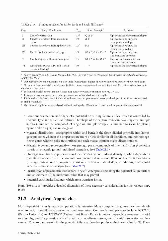
TABLE 21.3 Minimum Values for FS for Earth and Rock-fill Damsa,b
Case Design Conditions FSmin Shear Strengthc Remarks
I End of construction 1.3 d Q or Se Upstream and downstream slopesII Sudden drawdown from maximum
pool1.0 f R, S Upstream slope only, use
composite envelopeIII Sudden drawdown from spillway crest 1.2 f R, S Upstream slope only, use
composite envelopeIV Partial pool with steady seepage 1.5 (R + S)/2 for R < S Upstream slope only, use
intermediate envelopeV Steady seepage with maximum pool 1.5 (R + S)/2 for R < S Downstream slope only, use
intermediate envelopeVI Earthquake (Cases I, IV, and V with
seismic loading)1.0 — g Upstream and downstream slopes
a Source: From Wilson, S. D., and Marsal, R. J. 1979. Current Trends in Design and Construction of Embankment Dams.ASCE, New York.b Not applicable to embankments on clay shale foundations; higher FS values should be used for these conditions.c Q = quick (unconsolidated-undrained test), S = slow (consolidated-drained test), and R = intermediate (consoli-dated-undrained test).d For embankments more than 50 ft high over relatively weak foundation use FSmin = 1.4.e In zones where no excess pore-water pressures are anticipated use S strength.f FS should not be less than 1.5 when drawdown rate and pore-water pressures developed from flow nets are usedin stability analysisg Use shear strength for case analyzed without earthquake. (Values for FS are based on pseudostatic approach.)
© 2003 by CRC Press LLC
Stability of Slopes 21-5
programs are used routinely in virtually all geotechnical consulting offices. The following discussion isintended to present the salient features of the assumptions and analytical approach used to perform thestability analysis.
General
Failure, sudden or gradual, results when the mobilized stresses in a slope or its foundation equal theavailable strength. Limit equilibrium analysis is the basis for most methods available for slope stabilityevaluations. Consideration is given to a free body of the soil mass bounded by the slope and an assumed“slip” or failure surface. The known or assumed forces acting on the body and the shearing resistancerequired for stability are estimated. Most practical problems are statically indeterminate and requiresimplifying assumptions regarding the position and direction of forces to render the problem determinate.
The primary assumption of the limit equilibrium method is that the assumed strength can be mobilizedthroughout the length of the failure surface simultaneously. Strain compatibility is not considered. Thisassumption is applicable for stress–strain conditions that can be modeled as perfectly plastic at the failurestrength. When soils have some post-peak strength reduction (as with most natural soil), engineeringjudgment is required to select appropriate strength parameters and safety factors.
Two common free-body assumptions are illustrated in Fig. 21.2. In the cylindrical form shown inFig. 21.2(a), the mass weight W acting through lever arm E produces a driving moment. This momentis resisted by strength S mobilized along the failure surface of length L that acts through a lever arm R. Inthe simple wedge [Fig. 21.2(b)], strength S acting along the planar surface of length L resists the drivingforces resulting from gravity acting on weight W. A plane strain condition is assumed in most analyticalmethods currently in use so the potential failure mass is analyzed per unit width. Resistance that wouldbe generated at the lateral extremities of the failure zone are considered insignificant compared to thearea of the potential failure surface. When three-dimensional analyses are performed, FS(3-D) > FS(2-D)[Duncan, 1992] for most cases; therefore, two-dimensional analysis normally is conservative.
Common methods of analysis consider a system of forces. The soil mass is divided into a system of“slices,” “blocks,” or “wedges,” and force and/or moment equilibrium conditions are evaluated for theindividual components of the soil mass. The soil strength is uniformly adjusted by a scaling factor untilthe system is in a state of equilibrium. The actual soil strength divided by the strength required to satisfyequilibrium is defined as the factor of safety.
Slices as Free Bodies
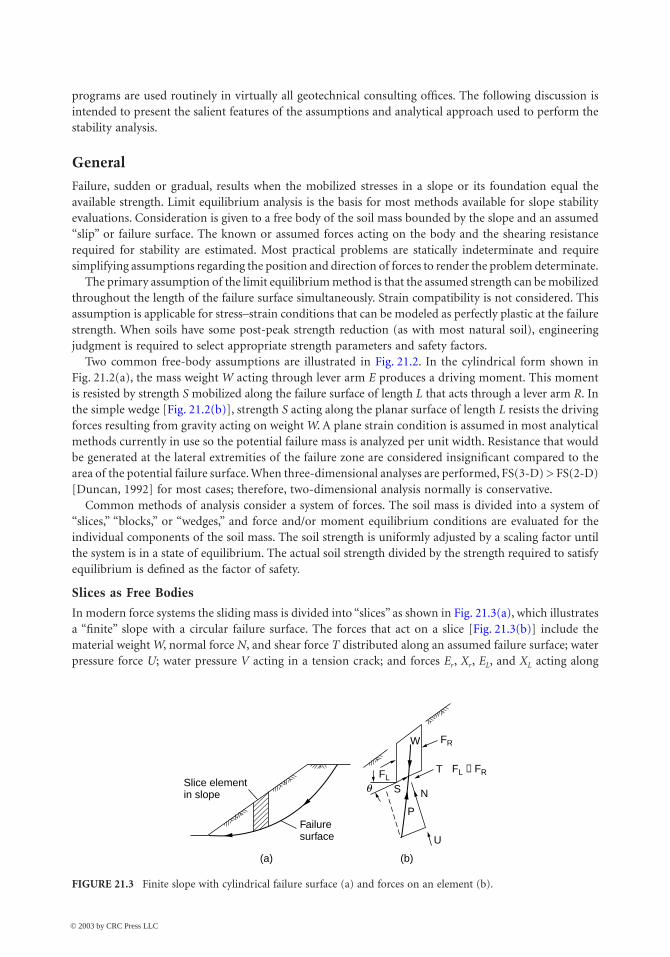
In modern force systems the sliding mass is divided into “slices” as shown in Fig. 21.3(a), which illustratesa “finite” slope with a circular failure surface. The forces that act on a slice [Fig. 21.3(b)] include thematerial weight W, normal force N, and shear force T distributed along an assumed failure surface; waterpressure force U; water pressure V acting in a tension crack; and forces Er, Xr, EL, and XL acting along
FIGURE 21.3 Finite slope with cylindrical failure surface (a) and forces on an element (b).
Slice elementin slope
Failuresurface
(a) (b)
FL ≠ FR
qFL
FRW
N
T
U
S
P
© 2003 by CRC Press LLC
21-6 The Civil Engineering Handbook, Second Edition
the sides of the slice. A discussion of the treatment of tension cracks can be found in Tschebotarioff[1973] and Spencer [1967]. Earthquakes impose dynamic forces in the form of the acceleration of gravityacting on the mass component.
Planar Surfaces, Blocks, and Wedges
Simple planar failures involve a single surface which can define a wedge in soil or rock [Fig. 21.2(b)], asliding block, or a wedge in rock with a tension crack. The force system is similar to that given in Fig. 21.3,except that the side forces are neglected. Complex planar failures involve a number of planes dividingthe mass into two or more blocks, and in addition to the force system for the single block, these solutionsprovide for interblock forces.
Infinite Slope
The infinite slope pertains where the depth to a planar failure surface is small compared to its length,which is considered as unlimited. Such conditions are found in slopes composed of the following:
• Cohesionless materials, such as clean sands
• Cohesive soils, such as residuum or colluvium, over a sloping rock surface at shallow depth
• OC fissured clays or clay shales with a uniformly deep, weathered zone
• Large slabs of sloping rock layers underlain by a weakness plane
Circular Failure Surfaces
General
In rotational slide failures, methods are available to analyze a circular or log-spiral failure surface, or asurface of any general shape. The location of the critical failure surface is found by determining the lowestvalue of safety factor obtained from a large number of assumed failure surface positions.
Slice Methods
Common to all slice methods is the assumption that the assumed soil mass and failure surface can bedivided into a finite number of slices. Equilibrium conditions are considered for all slices. The problemis strongly indeterminate, requiring several basic assumptions regarding the location of application orresultant directions of applied forces.
The slice methods can be divided into two groups: nonrigorous and rigorous. Nonrigorous methodssatisfy either force or moment equilibrium, whereas rigorous methods satisfy both force and momentequilibrium. The factor of safety estimated from rigorous methods is relatively insensitive to the assump-tions made to obtain determinacy [Duncan, 1992; Espinoza et al., 1992, 1994]. However, nonrigoroussolutions can produce significantly different estimates of safety depending on the assumptions made. Ingeneral, a nonrigorous solution satisfying only moment equilibrium is superior to one satisfying onlyforce equilibrium and will provide solutions close to a rigorous method.
Ordinary Method of Slices
The ordinary method of slices, also known as the Swedish method, was developed by Fellenius [1936]to analyze failures in homogeneous clays occurring along Swedish railways in the 1920s. The solution isa trial-and-error technique that locates the critical failure surface, or that circle with the lowest value forFS.
The ordinary method is not a rigorous solution because the shear and normal stresses and pore-waterpressures acting on the sides of the slice are not considered. In general the results are conservative. Inslopes with low f angles and moderate inclinations, FS may be 10 to 15% below the range of the moreexact solutions; with high f and slope inclination, FS can be underestimated by as much as 60%.
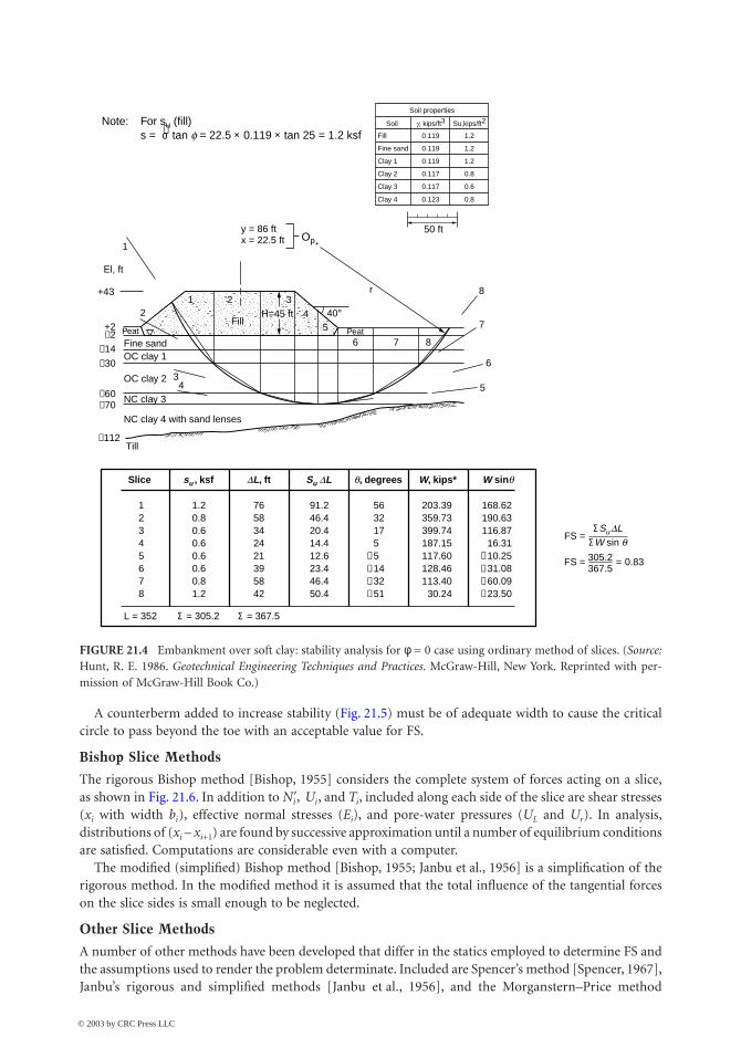
For the f = 0 case, normal stresses do not influence strength, and the ordinary method provides resultssimilar to rigorous methods [Johnson, 1974]. An example analysis using the ordinary method for thef = 0 case as applied to an embankment over soft ground is given in Fig. 21.4.
© 2003 by CRC Press LLC
Stability of Slopes 21-7
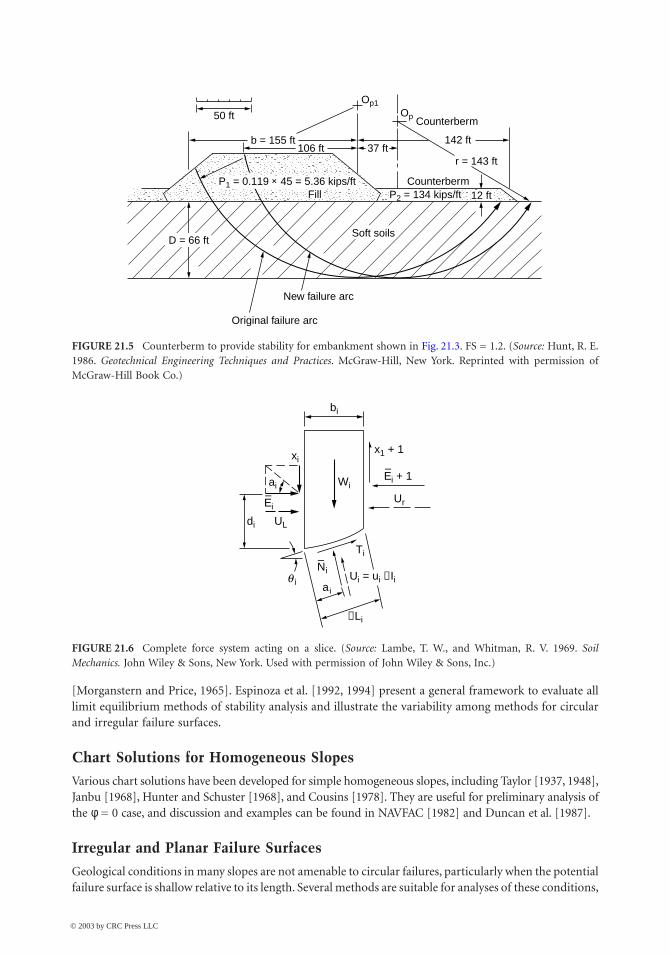
A counterberm added to increase stability (Fig. 21.5) must be of adequate width to cause the criticalcircle to pass beyond the toe with an acceptable value for FS.
Bishop Slice Methods
The rigorous Bishop method [Bishop, 1955] considers the complete system of forces acting on a slice,as shown in Fig. 21.6. In addition to N¢i , Ui, and Ti, included along each side of the slice are shear stresses(xi with width bi), effective normal stresses (Ei), and pore-water pressures (UL and Ur). In analysis,distributions of (xi – xi+1) are found by successive approximation until a number of equilibrium conditionsare satisfied. Computations are considerable even with a computer.
The modified (simplified) Bishop method [Bishop, 1955; Janbu et al., 1956] is a simplification of therigorous method. In the modified method it is assumed that the total influence of the tangential forceson the slice sides is small enough to be neglected.
Other Slice Methods
A number of other methods have been developed that differ in the statics employed to determine FS andthe assumptions used to render the problem determinate. Included are Spencer’s method [Spencer, 1967],Janbu’s rigorous and simplified methods [Janbu et al., 1956], and the Morganstern–Price method
FIGURE 21.4 Embankment over soft clay: stability analysis for f = 0 case using ordinary method of slices. (Source:Hunt, R. E. 1986. Geotechnical Engineering Techniques and Practices. McGraw-Hill, New York. Reprinted with per-mission of McGraw-Hill Book Co.)
Note: For su (fill)s = σ− tan f = 22.5 × 0.119 × tan 25 = 1.2 ksf
Soil properties
Soil
Fill 0.119 1.2
1.2
1.2
0.8
0.6
0.8
0.119
0.119
0.117
0.117
0.123
Fine sand
Clay 1
Clay 2
Clay 3
Clay 4
g, kips/ft3 Su,kips/ft2
Op+
50 ft
40°
y = 86 ftx = 22.5 ft
1 2
FillH=45 ft
3r
45
6
+43
Fine sandOC clay 1
OC clay 2
NC clay 3
NC clay 4 with sand lenses
Till
+2−2
−14
−30
−60−70
−112
2
7
7
8
8
6
534
1
El, ft
Peat Peat
Slice su , ksf DL, ft Su DL q, degrees W, kips* W sinq
1 1.2 76 91.2 56 203.39 168.622 0.8 58 46.4 32 359.73 190.633 0.6 34 20.4 17 399.74 116.874 0.6 24 14.4 5 187.15 16.315 0.6 21 12.6 −5 117.60 −10.256 0.6 39 23.4 −14 128.46 −31.087 0.8 58 46.4 −32 113.40 −60.098 1.2 42 50.4 −51 30.24 −23.50
L = 352 Σ = 305.2 Σ = 367.5
FS = ΣSu DL
ΣW sin q
FS = = 0.83305.2367.5
© 2003 by CRC Press LLC
21-8 The Civil Engineering Handbook, Second Edition
[Morganstern and Price, 1965]. Espinoza et al. [1992, 1994] present a general framework to evaluate alllimit equilibrium methods of stability analysis and illustrate the variability among methods for circularand irregular failure surfaces.
Chart Solutions for Homogeneous Slopes
Various chart solutions have been developed for simple homogeneous slopes, including Taylor [1937, 1948],Janbu [1968], Hunter and Schuster [1968], and Cousins [1978]. They are useful for preliminary analysis ofthe f = 0 case, and discussion and examples can be found in NAVFAC [1982] and Duncan et al. [1987].
Irregular and Planar Failure Surfaces
Geological conditions in many slopes are not amenable to circular failures, particularly when the potentialfailure surface is shallow relative to its length. Several methods are suitable for analyses of these conditions,
FIGURE 21.5 Counterberm to provide stability for embankment shown in Fig. 21.3. FS = 1.2. (Source: Hunt, R. E.1986. Geotechnical Engineering Techniques and Practices. McGraw-Hill, New York. Reprinted with permission ofMcGraw-Hill Book Co.)
FIGURE 21.6 Complete force system acting on a slice. (Source: Lambe, T. W., and Whitman, R. V. 1969. SoilMechanics. John Wiley & Sons, New York. Used with permission of John Wiley & Sons, Inc.)
50 ft
Op1Op Counterberm
142 ft
r = 143 ft
Counterberm
New failure arc
Original failure arc
37 ft106 ftb = 155 ft
Soft soilsD = 66 ft
P1 = 0.119 × 45 = 5.36 kips/ftFill P2 = 134 kips/ft 12 ft
bi
xix1 + 1
Ur
di
ai
Ui = ui ∆Ii
UL
Wi
∆Li
q i
Ti
ai
E–
i + 1
E–
i
N–
i
© 2003 by CRC Press LLC
Stability of Slopes 21-9
including Spencer’s method [Spencer, 1967], the Morganstern–Price method [Morganstern and Price,1965], and Janbu’s method [Janbu et al., 1956; Janbu, 1973].
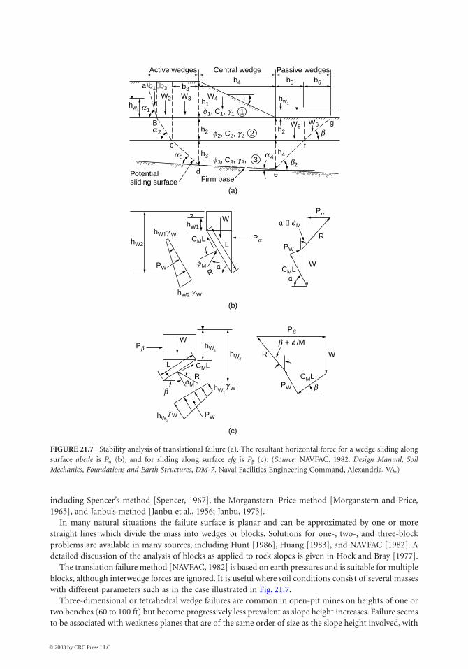
In many natural situations the failure surface is planar and can be approximated by one or morestraight lines which divide the mass into wedges or blocks. Solutions for one-, two-, and three-blockproblems are available in many sources, including Hunt [1986], Huang [1983], and NAVFAC [1982]. Adetailed discussion of the analysis of blocks as applied to rock slopes is given in Hoek and Bray [1977].
The translation failure method [NAVFAC, 1982] is based on earth pressures and is suitable for multipleblocks, although interwedge forces are ignored. It is useful where soil conditions consist of several masseswith different parameters such as in the case illustrated in Fig. 21.7.
Three-dimensional or tetrahedral wedge failures are common in open-pit mines on heights of one ortwo benches (60 to 100 ft) but become progressively less prevalent as slope height increases. Failure seemsto be associated with weakness planes that are of the same order of size as the slope height involved, with
FIGURE 21.7 Stability analysis of translational failure (a). The resultant horizontal force for a wedge sliding alongsurface abcde is Pa (b), and for sliding along surface efg is Pb (c). (Source: NAVFAC. 1982. Design Manual, SoilMechanics, Foundations and Earth Structures, DM-7. Naval Facilities Engineering Command, Alexandria, VA.)
W6
(a)
(b)
(c)
W
L
R
Active wedges Central wedge Passive wedgesb4
b3W2 W3 W4
W5
fc
B
f 1, C1, g 1
f 2, C2, g 2
f 3, C3, g 3,
h1
h2 h2
h3h4
PW
b1−b3
hw1
hw1
hW1
hW2 g W
hW2
PW
W
R
R WL
hW1CML
CML
Pb
Pb
α − f M
a
a 1
a 2
a 3
f M
f M
g W
g W
b + f /M
b b
g W
a 4b2
Pa
Pa
R
W
b
edPotentialsliding surface Firm base
i
b5 b6
g
2
3
1
αα
hW1
PW
PW
CML
hW1
CML
hW2
hW2
© 2003 by CRC Press LLC
21-10 The Civil Engineering Handbook, Second Edition
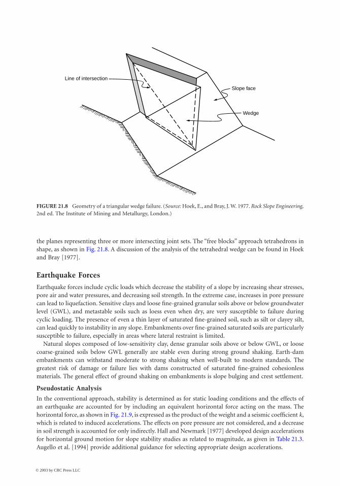
the planes representing three or more intersecting joint sets. The “free blocks” approach tetrahedrons inshape, as shown in Fig. 21.8. A discussion of the analysis of the tetrahedral wedge can be found in Hoekand Bray [1977].
Earthquake Forces
Earthquake forces include cyclic loads which decrease the stability of a slope by increasing shear stresses,pore air and water pressures, and decreasing soil strength. In the extreme case, increases in pore pressurecan lead to liquefaction. Sensitive clays and loose fine-grained granular soils above or below groundwaterlevel (GWL), and metastable soils such as loess even when dry, are very susceptible to failure duringcyclic loading. The presence of even a thin layer of saturated fine-grained soil, such as silt or clayey silt,can lead quickly to instability in any slope. Embankments over fine-grained saturated soils are particularlysusceptible to failure, especially in areas where lateral restraint is limited.
Natural slopes composed of low-sensitivity clay, dense granular soils above or below GWL, or loosecoarse-grained soils below GWL generally are stable even during strong ground shaking. Earth-damembankments can withstand moderate to strong shaking when well-built to modern standards. Thegreatest risk of damage or failure lies with dams constructed of saturated fine-grained cohesionlessmaterials. The general effect of ground shaking on embankments is slope bulging and crest settlement.
Pseudostatic Analysis
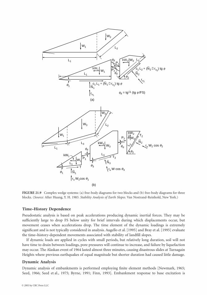
In the conventional approach, stability is determined as for static loading conditions and the effects ofan earthquake are accounted for by including an equivalent horizontal force acting on the mass. Thehorizontal force, as shown in Fig. 21.9, is expressed as the product of the weight and a seismic coefficient k,which is related to induced accelerations. The effects on pore pressure are not considered, and a decreasein soil strength is accounted for only indirectly. Hall and Newmark [1977] developed design accelerationsfor horizontal ground motion for slope stability studies as related to magnitude, as given in Table 21.3.Augello et al. [1994] provide additional guidance for selecting appropriate design accelerations.
FIGURE 21.8 Geometry of a triangular wedge failure. (Source: Hoek, E., and Bray, J. W. 1977. Rock Slope Engineering,2nd ed. The Institute of Mining and Metallurgy, London.)
Line of intersection
Slope face
Wedge
© 2003 by CRC Press LLC
Stability of Slopes 21-11
Time–History Dependence
Pseudostatic analysis is based on peak accelerations producing dynamic inertial forces. They may besufficiently large to drop FS below unity for brief intervals during which displacements occur, butmovement ceases when accelerations drop. The time element of the dynamic loadings is extremelysignificant and is not typically considered in analysis. Augello et al. [1995] and Bray et al. [1995] evaluatethe time–history-dependent movements associated with stability of landfill slopes.
If dynamic loads are applied in cycles with small periods, but relatively long duration, soil will nothave time to drain between loadings, pore pressures will continue to increase, and failure by liquefactionmay occur. The Alaskan event of 1964 lasted almost three minutes, causing disastrous slides at TurnagainHeights where previous earthquakes of equal magnitude but shorter duration had caused little damage.
Dynamic Analysis
Dynamic analysis of embankments is performed employing finite element methods [Newmark, 1965;Seed, 1966; Seed et al., 1975; Byrne, 1991; Finn, 1993]. Embankment response to base excitation is
FIGURE 21.9 Complex wedge systems: (a) free-body diagrams for two blocks and (b) free-body diagrams for threeblocks. (Source: After Huang, Y. H. 1983. Stability Analysis of Earth Slopes. Van Nostrand-Reinhold, New York.)
(a)
(b)
ru W1cos q1
ru W cos q3
ru W2 cos q2
N_
1
N_
3
N_
2
q1
fdqd
q3
W2
W3
W1
W1P1
P2 W2
W3
kW2
kW3
T
kW1
L1
L1
L3
L2
T3L3
T2
L 2
q1
q2
L1
ru1
ru2c1 L1 + (N
_1 − ru1
) tg f
c1 L2 + (N_
2 − ru2) tg f
N_
2fd
fd
fd = tg−1 (tg f /FS)
N_
1
W2
W1
L1
L2
kW1 W1
P1
P2
kW2 W2 L2
q2
© 2003 by CRC Press LLC
21-12 The Civil Engineering Handbook, Second Edition
evaluated and the dynamic stresses included in representative elements of the embankment are computedincorporating nonlinear dynamic material properties by using strain-dependent shear modulus anddamping values. Recent work includes the generation of excess pore-water pressure during dynamicloading and the onset of liquefaction. Both the overall deformations and the stability of the embankmentsection are evaluated.
21.4 Treatments to Improve Stability
General Concepts
Selection Basis
Slope treatments can be placed in one of two broad categories:
• Preventive treatments applied to stable, but potentially unstable natural slopes, slopes to be cut,sidehill fills to be placed, or embankments to be constructed
• Remedial or corrective treatments applied to existing unstable, moving slopes, or to failed slopes
The slope treatment selected is a function of the degree of the hazard and the risk to the public. Innatural slopes these factors are very much related to the form of slope failure (fall, slump, avalanche, orflow), the identification of which requires evaluation and prediction by an experienced engineeringgeologist.
Rating the Hazard and the Risk
Hazard degree relates to the potential failure itself in terms of its possible magnitude and probability ofoccurrence. Magnitudes can range from a small displacement and material volume, as is common inslump slides, to a large displacement and material volume, such as in a massive debris avalanche.Probability can range from certain to remote. Risk degree relates to the consequences of failure, such asa small volume of material covering portions of a roadway but not endangering lives, to the high riskfrom the failure of an earth dam resulting in the loss of many lives and much property damage. Safe buteconomical construction is always the desired result, but the acceptable degree of safety varies with thedegree of hazard and risk. An example of a rating system for hazard and risk is given in Hunt [1984].
Treatment Options
Avoid the High-Risk HazardThere are natural conditions where slope failure is essentially unpredictable and not preventable byreasonable means and the consequences are potentially disastrous. It is best to avoid construction inmountainous terrain subject to massive planar slides or avalanches, slopes in tropical climates subject todebris avalanches, or slopes subject to liquefaction and flows.
Accept the Failure HazardIn some cases, low to moderate hazards may be acceptable because postfailure cleanup is less costly thansome stabilization treatment. Examples are partial temporary closure of a roadway, which is often theapproach in underdeveloped countries, or a slide in an open-pit mine where failure is predictable butprevention is considered uneconomical.
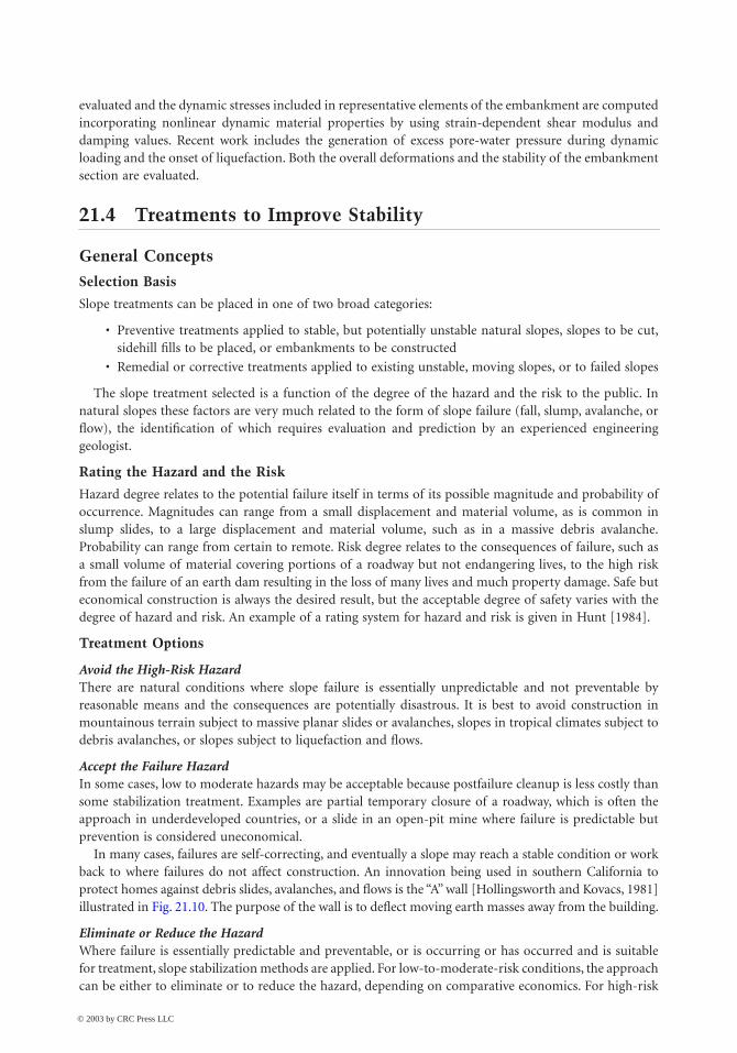
In many cases, failures are self-correcting, and eventually a slope may reach a stable condition or workback to where failures do not affect construction. An innovation being used in southern California toprotect homes against debris slides, avalanches, and flows is the “A” wall [Hollingsworth and Kovacs, 1981]illustrated in Fig. 21.10. The purpose of the wall is to deflect moving earth masses away from the building.
Eliminate or Reduce the HazardWhere failure is essentially predictable and preventable, or is occurring or has occurred and is suitablefor treatment, slope stabilization methods are applied. For low-to-moderate-risk conditions, the approachcan be either to eliminate or to reduce the hazard, depending on comparative economics. For high-risk
© 2003 by CRC Press LLC
Stability of Slopes 21-13
conditions the hazard should be eliminated. The generally acceptable safety factor determined by stabilityanalysis can be taken as follows: low risk, FS = 1.3; significant risk, FS = 1.4; high risk, FS = 1.5.
Slope Stabilization
Slope stabilization methods may be placed in five general categories, as follows (Fig. 21.11):
1. Change slope geometry to decrease the driving forces or increase the resisting forces.2. Control surface water to prevent erosion, and infiltration to reduce seepage forces.3. Control internal seepage to reduce the driving forces.4. Increase material strengths to increase resisting forces.5. Provide retention to increase the resisting forces.
Where slopes are in the process of failing, the time factor must be considered. Time may not be availablefor carrying out measures that will eliminate the hazard; therefore, the hazard should be reduced andperhaps eliminated at a later date. The objective is to arrest the immediate movement. Where possible,treatments should be performed during the dry season, when movements will not affect remediationsuch as breaking horizontal drains.
Changing Slope Geometry
Natural Slope Inclinations
In many cases the natural slope represents the maximum long-term inclination, but there are cases wherethe slope is not stable and is moving. The inclination of existing slopes should be noted during fieldreconnaissance, since an increase in inclination by cutting may result in failure.
Cut Slopes in Rock
The objective of any cut slope is to form a stable inclination without retention. Controlled blastingprocedures are required in rock masses to avoid excessive rock breakage resulting in extensive fracturing.Line drilling and presplitting during blasting operations minimize disturbance of the rock face.
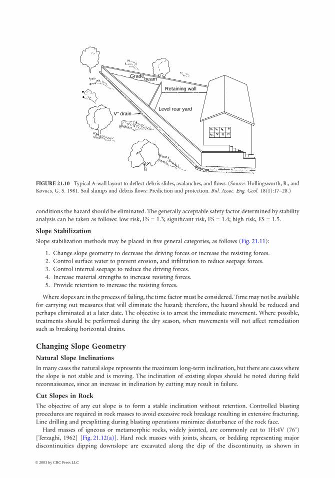
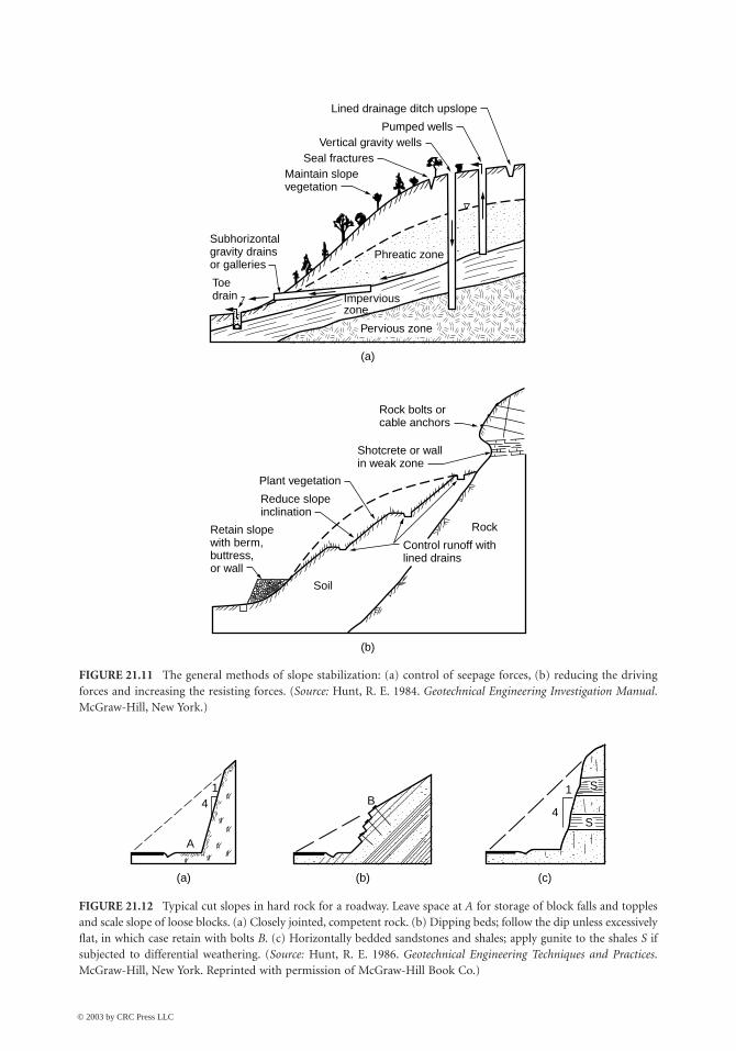
Hard masses of igneous or metamorphic rocks, widely jointed, are commonly cut to 1H:4V (76˚)[Terzaghi, 1962] [Fig. 21.12(a)]. Hard rock masses with joints, shears, or bedding representing majordiscontinuities dipping downslope are excavated along the dip of the discontinuity, as shown in
FIGURE 21.10 Typical A-wall layout to deflect debris slides, avalanches, and flows. (Source: Hollingsworth, R., andKovacs, G. S. 1981. Soil slumps and debris flows: Prediction and protection. Bul. Assoc. Eng. Geol. 18(1):17–28.)
Level rear yard
Retaining wall
beam
V" drain
Grade
© 2003 by CRC Press LLC
21-14 The Civil Engineering Handbook, Second Edition
FIGURE 21.11 The general methods of slope stabilization: (a) control of seepage forces, (b) reducing the drivingforces and increasing the resisting forces. (Source: Hunt, R. E. 1984. Geotechnical Engineering Investigation Manual.McGraw-Hill, New York.)
FIGURE 21.12 Typical cut slopes in hard rock for a roadway. Leave space at A for storage of block falls and topplesand scale slope of loose blocks. (a) Closely jointed, competent rock. (b) Dipping beds; follow the dip unless excessivelyflat, in which case retain with bolts B. (c) Horizontally bedded sandstones and shales; apply gunite to the shales S ifsubjected to differential weathering. (Source: Hunt, R. E. 1986. Geotechnical Engineering Techniques and Practices.McGraw-Hill, New York. Reprinted with permission of McGraw-Hill Book Co.)
Imperviouszone
(a)
(b)
Lined drainage ditch upslope
Pumped wellsVertical gravity wells
Seal fracturesMaintain slopevegetation
Subhorizontalgravity drainsor galleries
Toedrain
Pervious zone
Phreatic zone
Rock bolts orcable anchors
Shotcrete or wallin weak zone
Plant vegetation
Reduce slopeinclination
Soil
Rock
Control runoff withlined drains
Retain slopewith berm,buttress,or wall
14 B
4
1
A
(a) (b) (c)
S
S
© 2003 by CRC Press LLC
Stability of Slopes 21-15
Fig. 21.12(b). All material should be removed until the original slope is intercepted. If the dip is tooshallow for economical excavation, slabs can be retained with rock bolts (see “Retention,” later in thischapter).
Hard sedimentary rocks with bedding dipping vertically or into the face, or horizontally interbeddedhard sandstones and shales [Fig. 21.12(c)], are often cut to 1H:4V, but in the latter case, the shales shouldbe protected from weathering with shotcrete or gunite to retard differential weathering. Weathered orclosely jointed masses (except clay shales and dipping major discontinuities) require a reduction ininclination to between 1H:2V to 1H:1V (63˚ to 45˚) depending on conditions, or require some form ofretention. Clay shales, unless interbedded with sandstones, are often excavated to 6H:1V (9.5˚).
Benching has been common practice in high rock cuts but there is disagreement among practitionersas to its value. Some consider benches to be undesirable because they provide takeoff points for fallingblocks [Chassie and Goughnor, 1976]. To provide for storage they must be of adequate width. Blockstorage space should always be provided at the slope toe with adequate shoulder width to protect theroadway from falls and topples.
Cut Slopes in Soils
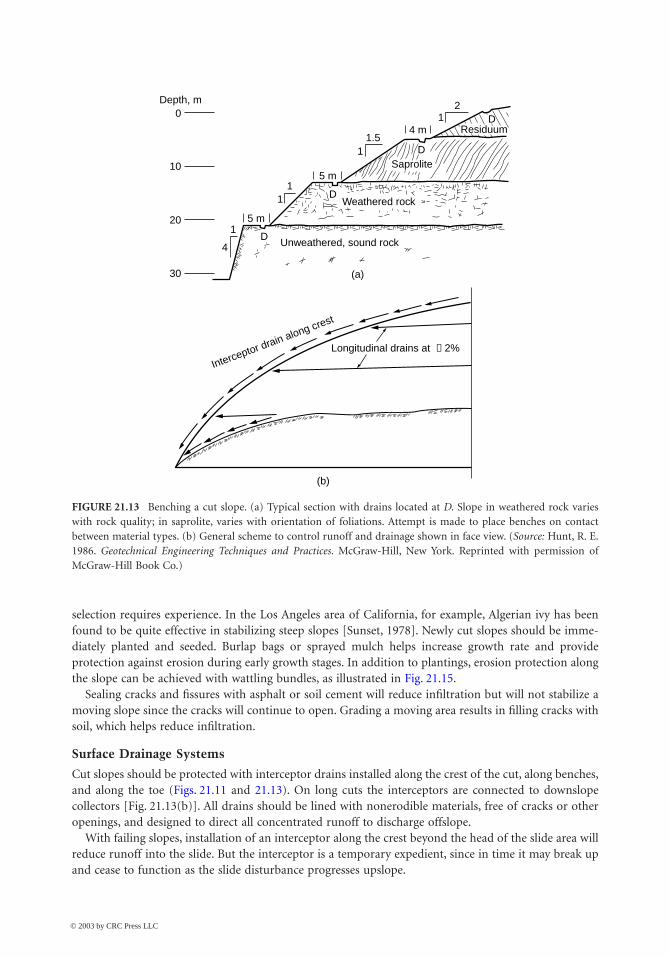
Most soil formations are commonly cut to an average inclination of 2H:1V (26˚) but consideration mustbe given to seepage forces and other physical and environmental factors to determine if retention isrequired. Soil cuts are normally designed with benches, especially for cuts over 25 to 30 ft high. Becausethe slope angle between benches may be increased, benches reduce the amount of excavation necessaryto achieve overall lower inclinations. Drains are installed as standard practice along the slopes and thebenches to control runoff, as illustrated in Fig. 21.11(b) and Fig. 21.13.
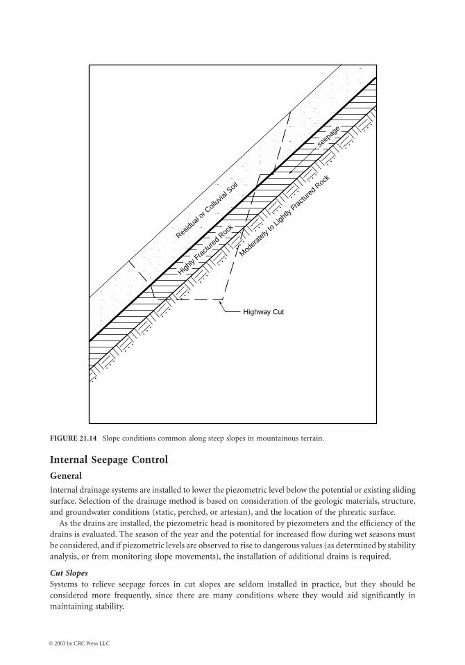
In soil–rock transition (strong residual soils to weathered rock) such as in Fig. 21.13, cuts are oftenexcavated to between 1H:2V to 1H:1V (63˚ to 45˚) although potential failure along relict discontinuitiesmust be considered. Where there is thin soil cover over rock the soil should be removed or retained asthe condition normally will be unstable in cut. Figure 21.13 illustrates an ideal case, often misinterpretedfrom test boring data, and not present in the slope. In mountainous terrain all of the formations maybe dipping, as shown on Fig. 21.14, a potentially very unstable condition. In such conditions, downslopeseismic refraction surveys are valuable to define stratigraphy.
Failing Slopes
If a slope is failing and undergoing substantial movement, the removal of material from the head toreduce the driving forces can be the quickest method of arresting movement, and benching may beeffective in the early stages. Placing material at the toe to form a counterberm increases the resistingforces. An alternative is to remove debris from the toe and permit failure to occur. Eventually the massmay naturally attain a stable inclination.
Changing slope geometry to achieve stability once failure has begun usually requires either the removalof very large volumes or the implementation of other methods. Space is seldom available in criticalsituations to permit placement of material at the toe, since very large volumes normally are required. Aswill be discussed, subhorizontal drains are often a very effective intermediate solution.
Surface Water Control
Purpose
Surface water is controlled to eliminate or reduce infiltration and to provide erosion protection. Externalmeasures are generally effective, however, only if the slope is stable and there is no internal source ofwater to cause excessive seepage forces.
Infiltration and Erosion Protection
Planting the slope with thick, fast-growing native vegetation strengthens the shallow soils with rootsystems and discourages desiccation, which causes fissuring. Not all vegetation works equally well, and
© 2003 by CRC Press LLC
21-16 The Civil Engineering Handbook, Second Edition
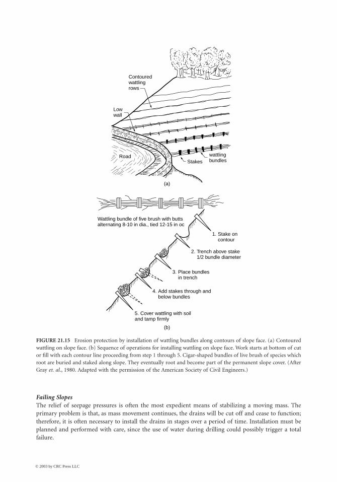
selection requires experience. In the Los Angeles area of California, for example, Algerian ivy has beenfound to be quite effective in stabilizing steep slopes [Sunset, 1978]. Newly cut slopes should be imme-diately planted and seeded. Burlap bags or sprayed mulch helps increase growth rate and provideprotection against erosion during early growth stages. In addition to plantings, erosion protection alongthe slope can be achieved with wattling bundles, as illustrated in Fig. 21.15.
Sealing cracks and fissures with asphalt or soil cement will reduce infiltration but will not stabilize amoving slope since the cracks will continue to open. Grading a moving area results in filling cracks withsoil, which helps reduce infiltration.
Surface Drainage Systems
Cut slopes should be protected with interceptor drains installed along the crest of the cut, along benches,and along the toe (Figs. 21.11 and 21.13). On long cuts the interceptors are connected to downslopecollectors [Fig. 21.13(b)]. All drains should be lined with nonerodible materials, free of cracks or otheropenings, and designed to direct all concentrated runoff to discharge offslope.
With failing slopes, installation of an interceptor along the crest beyond the head of the slide area willreduce runoff into the slide. But the interceptor is a temporary expedient, since in time it may break upand cease to function as the slide disturbance progresses upslope.
FIGURE 21.13 Benching a cut slope. (a) Typical section with drains located at D. Slope in weathered rock varieswith rock quality; in saprolite, varies with orientation of foliations. Attempt is made to place benches on contactbetween material types. (b) General scheme to control runoff and drainage shown in face view. (Source: Hunt, R. E.1986. Geotechnical Engineering Techniques and Practices. McGraw-Hill, New York. Reprinted with permission ofMcGraw-Hill Book Co.)
Depth, m0
10
20
4
1
1
1.5
1
1
12
D
D
D
Residuum
Saprolite
Weathered rock
Unweathered, sound rock
(a)
(b)
Longitudinal drains at ≈ 2%
Interceptor drain along crest
5 m
D
5 m
4 m
30
© 2003 by CRC Press LLC
Stability of Slopes 21-17
Internal Seepage Control
General
Internal drainage systems are installed to lower the piezometric level below the potential or existing slidingsurface. Selection of the drainage method is based on consideration of the geologic materials, structure,and groundwater conditions (static, perched, or artesian), and the location of the phreatic surface.
As the drains are installed, the piezometric head is monitored by piezometers and the efficiency of thedrains is evaluated. The season of the year and the potential for increased flow during wet seasons mustbe considered, and if piezometric levels are observed to rise to dangerous values (as determined by stabilityanalysis, or from monitoring slope movements), the installation of additional drains is required.
Cut SlopesSystems to relieve seepage forces in cut slopes are seldom installed in practice, but they should beconsidered more frequently, since there are many conditions where they would aid significantly inmaintaining stability.
FIGURE 21.14 Slope conditions common along steep slopes in mountainous terrain.
Moder
ately
to Lig
htly F
ractu
red R
ock
Highway Cut
Highly
Fractu
red R
ock
Residu
al or
Coll
uvial
Soil
seep
age
© 2003 by CRC Press LLC
21-18 The Civil Engineering Handbook, Second Edition
Failing SlopesThe relief of seepage pressures is often the most expedient means of stabilizing a moving mass. Theprimary problem is that, as mass movement continues, the drains will be cut off and cease to function;therefore, it is often necessary to install the drains in stages over a period of time. Installation must beplanned and performed with care, since the use of water during drilling could possibly trigger a totalfailure.
FIGURE 21.15 Erosion protection by installation of wattling bundles along contours of slope face. (a) Contouredwattling on slope face. (b) Sequence of operations for installing wattling on slope face. Work starts at bottom of cutor fill with each contour line proceeding from step 1 through 5. Cigar-shaped bundles of live brush of species whichroot are buried and staked along slope. They eventually root and become part of the permanent slope cover. (AfterGray et. al., 1980. Adapted with the permission of the American Society of Civil Engineers.)
Contouredwattlingrows
wattlingbundlesStakes
Road
Lowwall
Wattling bundle of five brush with buttsalternating 8-10 in dia., tied 12-15 in oc
1. Stake oncontour
2. Trench above stake1/2 bundle diameter
3. Place bundlesin trench
4. Add stakes through andbelow bundles
5. Cover wattling with soiland tamp firmly
(a)
(b)
© 2003 by CRC Press LLC
Stability of Slopes 21-19
Methods
Deep wells have been used to stabilize many deep-seated slide masses, but they are costly since continuousor frequent pumping is required. Check valves normally are installed so that when the water level rises,pumping begins. Deep wells are most effective if installed in relatively free-draining material below thefailing mass.
Vertical gravity drains are useful in perched water-table conditions where an impervious stratumoverlies an open, free-draining stratum with a lower piezometric level. The drains permit seepage bygravity through the confining stratum and thus relieve hydrostatic pressures. Clay strata over granularsoils, or clays or shales over open-jointed rock, offer favorable conditions for gravity drains where aperched water table exists.
Subhorizontal drains are one of the most effective methods to improve stability of a cut slope, or tostabilize a failing slope. Installed at a slight angle upslope to penetrate the phreatic zone and permitgravity flow, they usually consist of perforated pipe, 2 in. diameter or larger, forced into a predrilled holeof slightly larger diameter than the pipe. Horizontal drains have been installed to lengths of more than300 ft. Spacing depends on the type of material being drained; fine-grained soils may require spacing asclose as 10 to 30 ft, whereas for more permeable materials, 30 to 50 ft may suffice.
Drainage galleries are very effective for draining large moving masses but their installation is difficultand costly. They are used mostly in rock masses where roof support is less of a problem than in soils.Installed below the failure zone to be effective, they are often backfilled with stone. Vertical holes drilledinto the galleries from above provide for drainage from the failure zone into the galleries.
Interceptor trench drains can be installed upslope to intercept groundwater flowing into a cut or slidingmass, but they must be sufficiently deep. Perforated pipe is laid in the trench bottom, embedded in sand,and covered with free-draining material, then sealed at the surface. Interceptor trench drains are generallynot practical on steep, heavily vegetated slopes because installation of the drains and access roads requiresstripping the vegetation, which will tend to decrease stability.
Relief trenches relieve pore pressures at the slope toe. They are relatively simple to install. Excavationshould be made in sections and quickly backfilled with stone so as not to reduce the slope stability andpossibly cause a total failure. Generally, relief trenches are most effective for small slump slides wherehigh seepage forces in the toe area are the major cause of instability.
Electroosmosis has been used occasionally to stabilize silts and clayey silts, but the method is relativelycostly, and not a permanent solution unless operation is maintained.
Increased Strength
Chemicals have sometimes been injected to increase soil strength. In a number of instances the injectionof a quicklime slurry into predrilled holes has arrested slope movements as a result of the strength increasefrom chemical reaction with clays [Handy and Williams, 1967; Broms and Boman, 1979]. Strengthincrease in saltwater clays, however, was found to be low.
Resistance along an existing or potential failure surface can be increased with drilled piers [Oaklandand Chameau, 1989; Lippomann, 1989], shear pins (reinforced concrete dowels), or stone columns. Inthe latter case the increased resistance is obtained from a significantly higher friction angle obtained inthe stone along its width intercepting the failure surface.
Sidehill Fills
Failures
Construction of a sidehill embankment using slow-draining materials can be expected to block naturaldrainage and evaporation. As seepage pressures increase, particularly at the toe (as shown in Fig. 21.16),the embankment strains and concentric tension cracks form. The movements develop finally into arotational failure. Fills placed on moderately steep to steep slopes of residual or colluvial soils, in particular,
© 2003 by CRC Press LLC
21-20 The Civil Engineering Handbook, Second Edition
are prone to be unstable unless seepage is properly controlled, or the embankment is supported by aretaining structure.
Preventive Treatments
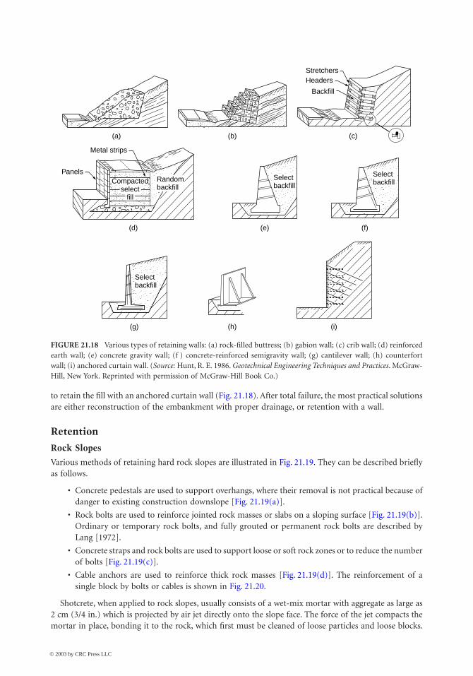
Interceptor trench drains should be installed along the upslope side of all sidehill fills as standard practiceto intercept flow, as shown in Fig. 21.17. Perforated pipe is laid in the trench bottom, embedded in sand,covered by free-draining materials, and then sealed at the surface. Surface flow is collected in open drainsand all discharge, including that from the trench drains, is directed away from the fill area.
Where anticipated flows are low to moderate, transverse drains extending downslope and connectingwith the interceptor ditches upslope, parallel to the roadway, may provide adequate subfill drainage.Wherever either the fill or the natural soils are slow-draining, however, a free-draining blanket shouldbe installed over the entire area between the fill and the natural slope materials to relieve seepage pressuresfrom shallow groundwater conditions (Fig. 21.17). It is prudent to strip potentially unstable upper soils,which are often creeping on moderately steep to steep slopes, to a depth where stronger soils areencountered. Stepped excavations improve stability. Discharge should be collected at the low point ofthe fill and drained downslope in a manner that will provide erosion protection.
Retaining structures may be economical on steep slopes that continue for some distance beyond thefill, if stability is uncertain.
Corrective Treatments
If movement downslope has begun in a slow initial failure stage, subhorizontal drains may be adequateto stabilize the embankment if closely spaced. They should be installed during the dry season, if practical,since the use of water to drill holes during the wet season may accelerate total failure. An alternative is
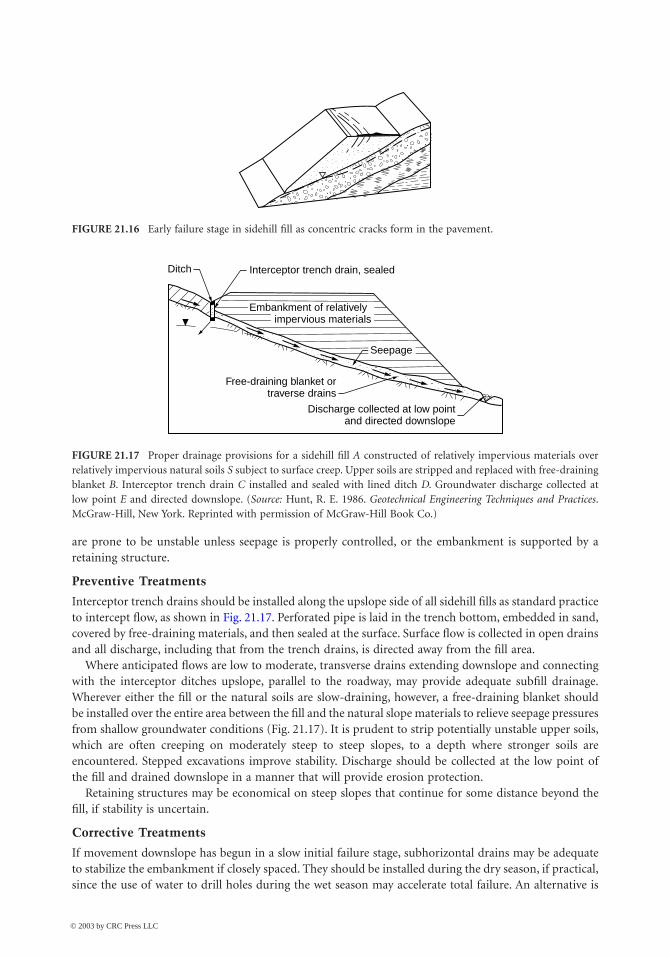
FIGURE 21.16 Early failure stage in sidehill fill as concentric cracks form in the pavement.
FIGURE 21.17 Proper drainage provisions for a sidehill fill A constructed of relatively impervious materials overrelatively impervious natural soils S subject to surface creep. Upper soils are stripped and replaced with free-drainingblanket B. Interceptor trench drain C installed and sealed with lined ditch D. Groundwater discharge collected atlow point E and directed downslope. (Source: Hunt, R. E. 1986. Geotechnical Engineering Techniques and Practices.McGraw-Hill, New York. Reprinted with permission of McGraw-Hill Book Co.)
Ditch Interceptor trench drain, sealed
Embankment of relatively impervious materials
Free-draining blanket ortraverse drains
Discharge collected at low pointand directed downslope
Seepage
© 2003 by CRC Press LLC
Stability of Slopes 21-21
to retain the fill with an anchored curtain wall (Fig. 21.18). After total failure, the most practical solutionsare either reconstruction of the embankment with proper drainage, or retention with a wall.
Retention
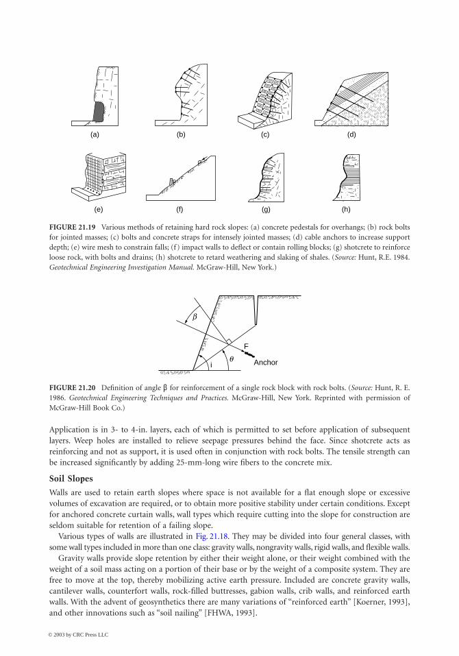
Rock Slopes
Various methods of retaining hard rock slopes are illustrated in Fig. 21.19. They can be described brieflyas follows.
• Concrete pedestals are used to support overhangs, where their removal is not practical because ofdanger to existing construction downslope [Fig. 21.19(a)].
• Rock bolts are used to reinforce jointed rock masses or slabs on a sloping surface [Fig. 21.19(b)].Ordinary or temporary rock bolts, and fully grouted or permanent rock bolts are described byLang [1972].
• Concrete straps and rock bolts are used to support loose or soft rock zones or to reduce the numberof bolts [Fig. 21.19(c)].
• Cable anchors are used to reinforce thick rock masses [Fig. 21.19(d)]. The reinforcement of asingle block by bolts or cables is shown in Fig. 21.20.
Shotcrete, when applied to rock slopes, usually consists of a wet-mix mortar with aggregate as large as2 cm (3/4 in.) which is projected by air jet directly onto the slope face. The force of the jet compacts themortar in place, bonding it to the rock, which first must be cleaned of loose particles and loose blocks.
FIGURE 21.18 Various types of retaining walls: (a) rock-filled buttress; (b) gabion wall; (c) crib wall; (d) reinforcedearth wall; (e) concrete gravity wall; (f ) concrete-reinforced semigravity wall; (g) cantilever wall; (h) counterfortwall; (i) anchored curtain wall. (Source: Hunt, R. E. 1986. Geotechnical Engineering Techniques and Practices. McGraw-Hill, New York. Reprinted with permission of McGraw-Hill Book Co.)
(a)
Metal strips
Panels
(d)
(g) (h) (i)
(e) (f)
(b) (c)
StretchersHeaders
Backfill
Randombackfill
Compactedselect
fill
Selectbackfill
Selectbackfill
Selectbackfill
© 2003 by CRC Press LLC
21-22 The Civil Engineering Handbook, Second Edition
Application is in 3- to 4-in. layers, each of which is permitted to set before application of subsequentlayers. Weep holes are installed to relieve seepage pressures behind the face. Since shotcrete acts asreinforcing and not as support, it is used often in conjunction with rock bolts. The tensile strength canbe increased significantly by adding 25-mm-long wire fibers to the concrete mix.
Soil Slopes
Walls are used to retain earth slopes where space is not available for a flat enough slope or excessivevolumes of excavation are required, or to obtain more positive stability under certain conditions. Exceptfor anchored concrete curtain walls, wall types which require cutting into the slope for construction areseldom suitable for retention of a failing slope.
Various types of walls are illustrated in Fig. 21.18. They may be divided into four general classes, withsome wall types included in more than one class: gravity walls, nongravity walls, rigid walls, and flexible walls.
Gravity walls provide slope retention by either their weight alone, or their weight combined with theweight of a soil mass acting on a portion of their base or by the weight of a composite system. They arefree to move at the top, thereby mobilizing active earth pressure. Included are concrete gravity walls,cantilever walls, counterfort walls, rock-filled buttresses, gabion walls, crib walls, and reinforced earthwalls. With the advent of geosynthetics there are many variations of “reinforced earth” [Koerner, 1993],and other innovations such as “soil nailing” [FHWA, 1993].
FIGURE 21.19 Various methods of retaining hard rock slopes: (a) concrete pedestals for overhangs; (b) rock boltsfor jointed masses; (c) bolts and concrete straps for intensely jointed masses; (d) cable anchors to increase supportdepth; (e) wire mesh to constrain falls; (f ) impact walls to deflect or contain rolling blocks; (g) shotcrete to reinforceloose rock, with bolts and drains; (h) shotcrete to retard weathering and slaking of shales. (Source: Hunt, R.E. 1984.Geotechnical Engineering Investigation Manual. McGraw-Hill, New York.)
FIGURE 21.20 Definition of angle b for reinforcement of a single rock block with rock bolts. (Source: Hunt, R. E.1986. Geotechnical Engineering Techniques and Practices. McGraw-Hill, New York. Reprinted with permission ofMcGraw-Hill Book Co.)
(a) (b) (c) (d)
(h)(g)(f)(e)
b
q
F
Anchori
© 2003 by CRC Press LLC

Stability of Slopes 21-23
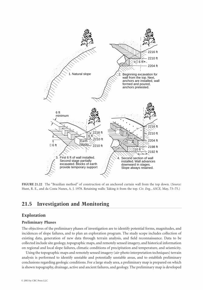
Nongravity walls are restrained at the top and not free to move. They include basement walls, somebridge abutments, and anchored concrete curtain walls. Anchored concrete curtain walls, such as the oneillustrated in Fig. 21.21, can be constructed to substantial heights and have a very high retention capacity.As illustrated in Fig. 21.22, they are constructed from the top down by excavation of a series of benches intothe slope and formation of a section of wall, retained by anchors, in each bench along the slope. Since theslope is thus retained completely during the wall construction, the system is particularly suited to potentiallyunstable or unstable slopes. A variation of the anchored curtain wall consists of anchored premolded concretepanels. The advantage of the system is that the wall easily conforms to the slope configuration.
Rigid walls include concrete walls, gravity and semigravity walls, cantilever walls, and counterfortwalls. Anchored concrete curtain walls are considered as semirigid. Flexible walls include rock-filledbuttresses, gabion walls, crib walls, reinforced earth walls, and anchored sheet-pile walls.
EmbankmentsEarth Dams
During design and construction of earth dams, stability is provided by controlled compaction of theembankment materials, adequate support by founding materials, and control of seepage through andbeneath the embankment. Stable slope inclinations are related to the materials used to construct theembankment, and to the foundation materials. Relatively weak foundation materials either requireremoval by excavation or the flattening of embankment slopes.
Control of seepage through, beneath, and around the embankment is a critical aspect of design andconstruction. In addition to water loss in a reservoir, uncontrolled seepage can result in internal erosionof the embankment or high uplift pressures in the foundation, either of which can lead to complete failure.
Embankments over Soft Ground
Failures usually occur during or shortly after construction when embankments are raised over softfoundation soils. The major postconstruction concern is long-term settlements. In most situations it isdesirable to avoid failure because the remolding of the soils that occurs significantly decreases theirstrength, worsening the situation. Therefore, embankments are constructed in stages. During each stageconsolidation and strength increase occurs in the foundation soils, enabling the construction of sub-sequent stages [Ladd, 1991]. Vertical drains, such as wick drains, significantly increase the rate ofconsolidation and shorten the time interval between stages.
Geosynthetics are used to improve embankment strength. They may be placed on the soft groundprior to placing the first lift, and then subsequently placed within the embankment. Hird [1986] andLow et al. [1990] provide methods for assessing stability of reinforced embankments on soft ground.Construction of counterberms (Fig. 21.5) also improves stability.
FIGURE 21.21 Section through a 25.5 m (85 ft) high anchored curtain wall constructed to retain a steep slope witha history of landslides. Joao Monlavade, M. G. Brazil. (Source: Hunt, R. E., and da Costa Nunes, A. J. 1978. Retainingwalls: Taking it from the top. Civ. Eng., ASCE, May, 73–75.)
2330
2297
2264
2231
Excavation forsteel plant
Anchored curtainwall
Colluvium
Fracture
40° slope
Residualsoils
Saprolite,highlydecom-posed rock
Fracturedrock,becomingsound
Ele
vatio
n, ft
2198
2165
2132
L = 79°
© 2003 by CRC Press LLC
21-24 The Civil Engineering Handbook, Second Edition
21.5 Investigation and Monitoring
Exploration
Preliminary Phases
The objectives of the preliminary phases of investigation are to identify potential forms, magnitudes, andincidences of slope failures, and to plan an exploration program. The study scope includes collection ofexisting data, generation of new data through terrain analysis, and field reconnaissance. Data to becollected include site geology, topographic maps, and remotely sensed imagery, and historical informationon regional and local slope failures, climatic conditions of precipitation and temperature, and seismicity.
Using the topographic maps and remotely sensed imagery (air-photo interpretation techniques) terrainanalysis is performed to identify unstable and potentially unstable areas, and to establish preliminaryconclusions regarding geologic conditions. For a large study area, a preliminary map is prepared on whichis shown topography, drainage, active and ancient failures, and geology. The preliminary map is developed
FIGURE 21.22 The “Brazilian method” of construction of an anchored curtain wall from the top down. (Source:Hunt, R. E., and da Costa Nunes, A. J. 1978. Retaining walls: Taking it from the top. Civ. Eng., ASCE, May, 73–75.)
1. Natural slope 2. Beginning excavation forwall from the top. Next,anchors are installed, wallformed and poured,anchors pretested.
3. First 6 ft of wall installed.Second stage partiallyexcavated. Blocks of earthprovide temporary support
4. Second section of wallinstalled. Wall advancesdownward in stages.Slope always retained.
2216 ft
2210 ft
2204 ft≈ 6 ft
≈ 6 ft≈ 10 ft
6 ft2216 ft
2216 ft
2210 ft
2204 ft
2198 ft
2192 ft
Earthblocks
2210 ft
2210 ft
6 ftminimum
© 2003 by CRC Press LLC
Stability of Slopes 21-25
into a hazard map after field reconnaissance. At the project location, more detailed maps are preparedillustrating the foregoing items. The methodology identifies the significant features to be examined duringfield reconnaissance.
The site location is visited and notations are made regarding seepage points, vegetation, creep indica-tions (tilted and bent tree trunks), tension cracks, failure scars, hummocky ground, natural slope incli-nations, exposed geology, and prevailing and recent weather conditions.
From the data collected, preliminary evaluations are made regarding slope conditions and an explo-ration program is planned. The entire slope should be explored, not only the specific area of failure orarea to be cut.
Explorations
Seismic refraction profiling is useful to determine the depth to sound rock and the probable groundwatertable, and is most useful in differentiating between colluvial or residual soils and the fractured-rock zone.Surveys are made both longitudinal and transverse to the slope. They are particularly valuable on steepslopes with a deep weathering profile where test borings are time-consuming and costly.
Resistivity profiling may be performed to determine the depth to groundwater and to rock. Profilingis generally only applicable to depths of about 15 to 30 ft, but very useful in areas of difficult access. Inthe soft, sensitive clays of Sweden, the failure surface or potential failure surface is often located byresistivity measurements since the salt content, and therefore the resistivity, often changes suddenly atthe slip surface [Broms, 1975].
Test borings are made to confirm the stratigraphy determined by the geophysical explorations, torecover samples of the various materials, and to provide holes for the installation of instrumentation.Borings should extend to adequate penetration below the depth of a cut, and below the depth of anypotential failure surface. Sampling should be continuous through a potential or existing rupture zone,and in residual soils and rock masses care should be taken to identify slickensided surfaces. Groundwaterconditions must be defined carefully and the static water table, perched, and artesian conditions noted.It is important to remember that the conditions existing at the time of investigation are not likely to bethose during failure.
Evaluations
Evaluations are made of the safety factor against total failure on the basis of existing topographicconditions, then under conditions of the imposed cut or fill. For preliminary studies, shear strengthsmay be estimated from published data, or measured by laboratory or in situ testing. In the selection ofthe strength parameters, consideration is given to field conditions as well as to changes that may occurwith time (reduction from weathering, leaching, solution). Other transient conditions such as weatherand earthquakes also require consideration, especially if the safety factor for the entire slope is low andcould go below unity with some environmental change.
Instrumentation and Monitoring
Purpose
Where movement is occurring, where safety factors against sliding are low, or where a major work wouldbecome endangered by a slope failure, instrumentation is required to monitor changing conditions andprovide early warning of impending failure.
Slope–stability analysis is far from an exact science, regardless of the adequacy of the data available,and sometimes the provision for an absolutely safe slope is prohibitively costly.
In cut slopes, instrumentation monitors movements and changing stress conditions to provide earlywarning and permit invoking contingency plans for remedial measures when low safety factors areaccepted in design. In unstable or moving slopes, instrumentation is installed to locate the failure surfaceand determine pore-water pressures for analysis, and to measure surface and subsurface movements,velocities, and accelerations which provide indications of impending total failure.
© 2003 by CRC Press LLC
21-26 The Civil Engineering Handbook, Second Edition
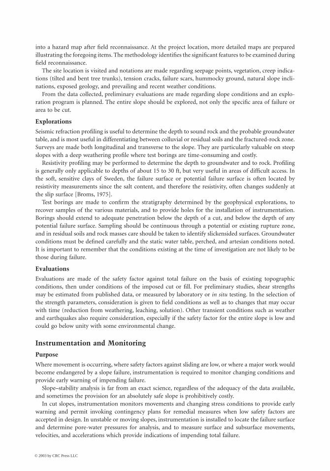
Methods Summarized
Instrumentation is discussed in detail in Hunt [1984] and Dunnicliff [1988], and for slopes is illustratedin Fig. 21.23. Surface movements are monitored by survey nets, tiltmeters (on benches), convergencemeters, surface extensometers, and terrestrial photography. Subsurface deformations are monitored withinclinometers, deflectometers, shear-strip indicators, steel wire and weights in boreholes, and the acous-tical emissions device. Pore-water pressures are monitored with piezometers.
All instruments should be monitored periodically and the data plotted as it is obtained to showchanging conditions. Movement accelerations are most significant.
References
Augello, A. J., Bray, J. D., Leonards, G. A., Repetto, P. C., and Byrne, R. J. 1995. Response of landfills toseismic loading. Proceedings, Geoenvironment 2000, ASCE (in press).
Bishop, A. W. 1955. The use of the slip circle in the stability analysis of earth slopes. Geotechnique.5(1):7–17.
FIGURE 21.23 Slope instrumentation and monitoring: (a) potentially unstable soil slope and (b) rock cut. (Source:Hunt, R. E. 1984. Geotechnical Engineering Investigation Manual. McGraw-Hill, New York.)
Legend:( a ) precise surveying( g ) convergence meter( h ) strain meter( L ) inclinometer( n ) shear-strip indicator( q ) acoustical emissions device( r ) piezometer
Legend:( a ) precise surveying( e ) tiltmeter( g ) convergence meter( h ) strain meter( i ) terrestial photography( j ) vibration monitoring( L ) inclinometer(m) deflectometer( n ) shear-strip indicator( o ) borehole extensometer( q ) acoustical emissions device( r ) piezometers
( a )
(a,i)
( a )( o )
( o )
( o )
(e,g)
(e,g)
(e,g)
Tensioncracks( h )
(e,g)
(q,n)
(L or m,r, q, n)
(L or m, r, q, n)
( j )
( g )
(q,r)
(L,n,q,r)
(L,n,q,r)
( h )
( g )
Tensioncrack
Potentialfailuresurface
© 2003 by CRC Press LLC
Stability of Slopes 21-27
Bjerrum, L. 1973. Problems of soil mechanics and construction on soft clays and structurally unstablesoils. In Proc. 8th Int. Conf. Soil Mech. Found. Eng. 3:111–159.
Brand, E. W. 1982. Analysis and design in residual soils. In Proc. Conf. Eng. Constr. Tropical Soils. ASCE,Honolulu, pp. 89–143.
Bray, J. D., Augello, A. J., Repetto, P. C., Leonards, G. A., and Byrne, R. J. 1995. Seismic analyticalprocedures for solid waste landfills. J. Geotech. Eng., ASCE (in press).
Broms, B. B. 1975. Foundation Engineering Handbook, H. F. Winterkorn and H. Y. Fang, editors, VanNostrand Reinhold, New York, pp. 373–401.
Broms, B. B., and Boman, P. 1979. Lime columns — A new foundation method. J. Geotech. Eng., ASCE.105(GT4):539–556.
Byrne, P. M. 1991. A cyclic shear-volume coupling and pore pressure model for sand. In Proc. 2nd Int.Conf. Recent Adv. Geotech. Earth. Eng. Soil Dynamics. Rolla, I:47–56.
Chassie, R. G., and Goughnor, R. D. 1976. States intensifying efforts to reduce highway landslides. Civ.Eng., Apr., p. 65.
Chirapuntu, S., and Duncan, J. M. 1976. The role of fill strength in the stability of embankments on softclay. University of California, Berkeley, NITS AD-A027-087.
Cousins, B. F. 1978. Stability charts for simple earth slopes. J. Geotech. Eng. ASCE. 104(GT5):267–279.Deere, D. U. 1976. Dams on rock foundations — Some design questions. In Proc. Rock Eng. Found. Slopes.
ASCE, New York, pp. 55–85.Duncan, J. M. 1992. State-of-the-art: Static stability and deformation analysis. Proc. ASCE, Stability and
Performance of Slopes and Embankments — II. Geotech. Spec. Pub. No. 1(31):222–266.Duncan, J. M., Buchignani, A. L., and De Wet, M. 1987. An Engineering Manual for Slope Stability Studies.
Virginia Tech Report.Dunnicliff, J. 1988. Geotechnical Instrumentation for Monitoring Field Performance. John Wiley & Sons,
New York.Espinoza, R. D., Bourdeau, P. L., and Muhunthan, B. 1994. Unified formulation for analysis of slopes
with general slip surfaces. J. Geotech. Eng. ASCE. 120(7):1185–1204.Espinoza, R. D., Repetto, P. C., and Muhunthan, B. 1992. General framework for stability analysis of
slopes. Geotechnique. 42(4):603–616.Fellenius, W. 1936. Calculation of the stability of earth dams. Trans. 2nd Cong. Large Dams, Vol. 4,
Washington, D.C.FHWA. 1993. FHWA Tour for Geotechnology — Soil Nailing. U.S. Department of Transportation, Federal
Highway Administration, Washington, D.C.Finn, W. D. L. 1993. Practical studies of the seismic response of a rockfill dam and a tailings impoundment.
In Proc. 3rd Int. Conf. Case Histories Geotech. Eng. St. Louis.Gray, D. H., Leiser, A. T., and White, C. A. 1980. Combined vegetative-structural slope stabilization. Civ.
Eng., ASCE. October, pp. 73–77.Hall, W. J., and Newmark, N. M. 1977. Seismic design criteria for pipelines and facilities. In The Current
State of Knowledge of Lifeline Earthquake Engineering, Proc. ASCE, New York, pp. 18–34.Handy, R. L., and Williams, W. W. 1967. Chemical stabilization of an active landslide. Civ. Eng., August,
pp. 62–65.Hird, C. C. 1986. Stability charts for reinforced embankments on soft ground. Geotext. Geomembr.
4(2):107–127.Hoek, E., and Bray, J. W. 1977. Rock Slope Engineering, 2nd ed. The Institute of Mining and Metallurgy,
London.Hollingsworth, R., and Kovacs, G. S. 1981. Soil slumps and debris flows: Prediction and protection. Bul.
Assoc. Eng. Geol. 18(1):17–28.Huang, Y. H. 1983. Stability Analysis of Earth Slopes. Van Nostrand-Reinhold, New York.Hunt, R. E. 1984. Geotechnical Engineering Investigation Manual. McGraw-Hill, New York.Hunt, R. E. 1986. Geotechnical Engineering Techniques and Practices. McGraw-Hill, New York.Hunt, R. E., and da Costa Nunes, A. J. 1978. Retaining walls: Taking it from the top. Civ. Eng., May, pp. 73–75.
© 2003 by CRC Press LLC
21-28 The Civil Engineering Handbook, Second Edition
Hunter, J. H., and Schuster, R. L. 1968. Stability of simple cuttings in normally consolidated clays.Geotechnique. 13(3):372–378.
Janbu, N. 1968. Slope Stability Computations. Soil Mechanics and Foundation Engineering Report, TheTechnical University of Norway.
Janbu, N. 1973. Slope Stability Computations. In Embankment Dam Engineering, eds. R. C. Hirschfieldand S. J. Poulos, pp. 47–86. John Wiley & Sons, New York.
Janbu, N., Bjerrum, L., and Kjaernsli, B. 1956. Soil Mechanics Applied to Some Engineering Problems, pp.5–26. Norwegian Geotechnical Institute, Oslo, Publ. 16.
Johnson, S. J. 1974. Analysis and design relating to embankments. In Proc. ASCE Conf. Anal. DesignGeotech. Eng. Austin, Texas, Vol. II, pp. 1–48.
Koerner, R. M. 1993. Designing with Geosynthetics, 3rd ed. Prentice Hall, Englewood Cliffs, NJ.Ladd, C. C. 1991. Stability evaluation during staged construction. J. Geotech. Eng., ASCE. 117(4):540–615.Lamb, T. W., and Whitman, R. V. 1969. Soil Mechanics. John Wiley & Sons, New York.Lang, T. A. 1972. Rock reinforcement. Bull. Assoc. Eng. Geol. 9(3):215–239.Leonards, G. A. 1979. Stability of slopes in soft clays. In 6th Panamerican Conf. Soil Mech. Found. Eng.
1:225–274.Leonards, G. A. 1982. Investigation of failures. J. Geotech. Eng., ASCE. 108(GT2):187–246.Lippomann, R. 1989. Dowelled clay slopes: Recent example. In Proc. 12th Int. Conf. Soil Mech. Found.
Eng. Rio de Janeiro, 2:1269–1271.Low, B. K., Wong, K. S., Lim, C., and Broms, B. B. 1990. Slip circle analysis of reinforced embankments
on soft ground. Geotext. Geomembr. 9(2):165–181.Lowe, J., III. 1967. Stability analysis of embankments. J. Soil Mech. Found., ASCE. 93(SM4):1–34.Morganstern, N. R., and Price, V. E. 1965. The analysis of the stability of general slip surfaces. Geotech-
nique. 15(1):79–93.NAVFAC. 1982. Design Manual, Soil Mechanics, Foundations and Earth Structures, DM-7. Naval Facilities
Engineering Command, Alexandria, VA.Newmark, N. M. 1965. Effects of earthquakes on dams and embankments. Geotechnique. 15(2):139–160.Oakland, M. W., and Chameau, J. L. 1989. Analysis of drilled piers used for slope stabilization. Trans.
Res. Rec. 1219:21–32.Patton, F. D., and Hendron, A. J., Jr. 1974. General report on mass movements. In Proc. 2nd Int. Cong.
Int. Assoc. Eng. Geol. S–ao Paulo, p. V-GR 1.Seed, H. B. 1966. A method for earthquake resistant design of earth dams. J. Soil Mech. Found., ASCE.
92(SM1):13–41.Seed, H. B., Idriss, I. M., Lee, K. L., and Makdisi, F. I. 1975. Dynamic analysis of the slide of the lower
San Fernando Dam during the earthquake of February 9, 1971. J. Geotech. Eng., ASCE.101(GT9):889–911.
Spencer, E. 1967. A method of analysis of the stability of embankments assuming parallel inter-sliceforces. Geotechnique. 17(1):11–26.
Sunset. 1978. If hillside slides threaten in southern California, November is planting action month. SunsetMagazine, November, pp. 122–126.
Taylor, D. W. 1937. Stability analysis of earth slopes. Journal of the Boston Society of Civil Engineers, 24(3).Reprinted in Contributions to Soil Mechanics 1925–1940, BSCE, 1940, pp. 337–386.
Taylor, D. W. 1948. Fundamentals of Soil Mechanics. John Wiley & Sons, New York.Terzaghi, K. 1962. Stability of steep slopes on hard, unweathered rock. Geotechnique. 12(4):251–270.Tschebotarioff, G. P. 1973. Foundations, Retaining and Earth Structures. McGraw-Hill, New York.Vulliet, L., and Hutter, K. 1988. Viscous-type sliding laws for landslides. Can. Geotech. J. 25(3):467–477.Wilson, S. D., and Marsal, R. J. 1979. Current Trends in Design and Construction of Embankment Dams.
ASCE, New York.
© 2003 by CRC Press LLC