Embed Size (px)
Citation preview

႔ Chapter-21 Servicing and Maintenance
21-1
Chapter - 21 Servicing and Maintenance
chilled water plant equipmen (procedures) (documentation) (check list) ႔ ၍ ႕ (procedures) form troubleshooting procedure ႔
၂၁.၁ Pressure Testing System ႔
“Pressure Test” System ၍ refrigerant system ႔
Discharge service valve suction service valve ႔ (mid position) system ႔ (compressed) ႔ 50 psi ႔ ႔ stop valve system pressure
႔ stop valve (၁၂) ႔ system pressure pressure (pressure) system (leak) (compressed air) ႔
၂၁-၁ Trouble shooting of charge conditions

႔
21-2
႔ ၍ (guidelines for nitrogen pressure testing)
( ) R-22 system ( ) R-134a system ( ) R- R-123 system
၂၁.၂ Vacuum Drawing ႔ System Evacuation ၍ (leak) refrigerant
Chiller ႔ refrigerant chiller ႔ ႔ ႔ “ o ”
(၂၁-၂) evacuation 2 torr ႔ 2 mmHg ႔ vacuum pump System vacuum 2 torr ႔ stop valve ၍ vacuum pump ႔ Vacuum pressure system ႔ ၍ ႔ ႔ vacuum 2 torr ႔ vacuum ၍ stop valve vacuum pressure (l 2 torr ႔ vacuum pressure system ႔ ႔
၍ 2 torr ႔ vacuum pump dilution method ၍ system ႔ refrigerant ႔ ႔ (၃၀) ႔ system vacuum (၃) system ႔ ႕ Vacuum pump vacuum refrigerant ႔ ႔ (dilute )
၂၁-၂ System ႔ (dehydration)
System ႔ (dehydration) Wet Bulb (temperature) 32°F ႔ (pressure) 5mm Hg / 5000 microns

႔ Chapter-21 Servicing and Maintenance
21-3
၂၁.၃ System ႔ Refrigerant (Methods of Charging) Refrigerant
၁ charging by weight)
၂ (charging by superheat) Fixed o ႔
၃ - oo (charging by sub-cooled) Thermal expansion ႔
- oo
၂၁.၃.၁ Superheat Method (charging by superheat) fixed orifice
system (A) Measure entering dry bulb temperature of evaporator
(B) Measure entering dry bulb temperature at condenser
(C) Using charging table to determine recommended superheat (within + 5°F of chart reading)
(D) Calculate the actual superheat (E) If actual superheat is greater than recommended superheat, charge must be added.
(F) If actual superheat is less than the recommended value, charge must be removed
Superheat Charging Chart
၂၁-၃ Superheat charging chart
၂၁.၃.၂ Subcooling Method - oo (charging by sub-cooled) thermal
expansion valve system

႔
21-4
(A) Measure liquid line operating pressure. Convert the pressure into saturation
temperature using PT chart. (B) Measure actual liquid line temperature. (C) Calculate the subcooling and compare with equipment manual desired subcooling
(tolerance of 2-3 °C). (D) If subcooling is too low- insufficient charge. (E) If subcooling is too high- overcharged.
၂၁-၄ Measure subcooling ၂၁-၅ Charging by superheat method
System system ႔ refrigerant ႔ (vapor charging) (liquid charging) ၍
၂၁.၃.၃ ( ) ႔ (Vapor Charging) System ႔ refrigerant ႔ system
refrigerant vapor charging Vapor charging compressor ၏ suction ႔ refrigerant ႔၏ (specific volume) ႔ ႔
(၂၁-၆) o Evacuate refrigerant service valve valve ၍ ႔ ႔ refrigerant ႔ ႔ ႔ ႔ service valve ႔
႔ ႔ refrigerant ၏ ႔ suction service valve ႔ ႕ compressor Refrigerant valve ႔ valve suction pressure 30 psi ၍ ႔ refrigerant ၍ gas system ႔ valve suction service valve ႔

႔ Chapter-21 Servicing and Maintenance
21-5
Refrigerant ႔ ႔ o ႔ ၍
၂၁-၆ refrigerant (charging from low side)
refrigerant (charging from low side) (၁) Stop the compressor.
(၂) Know the refrigerant in the system, and get the correct refrigerant to be charged.
(၃) Attach the refrigerant cylinder or canister to the center o o o set.
(၄) o o o o , regulator. (Do o o ose the regulators after purging)
(၅) Attach o o o o , o o o conditioning unit. Make sure that the protective cap of the service valve is taken out.
(၆) O o o o .
(၇) Throttle the o . w condensing pressure of the refrigerant.
(၈) Operate the air conditioning unit.
(၉) C o o w ow s the design operating pressure.
(၁၀) The charge should be adequate once the design pressure on the low side is reached, but it is good to check the superheat, and make sure that the sight glass is clear.
(၁၁) Stop the air conditioning unit if the subcooling is inadequate. Repeat steps (7) to (10) until the charging is adequate
၂၁.၃.၄ ( ) (Liquid Charging) System ႔ refrigerant
႔ (charging time) (high pressure side) liquid charging valve

႔
21-6
(၂၁-၇) liquid charging valve valve purge liquid charging valve ႔ refrigerant ၍
Liquid receiver outlet valve compressor ႔ liquid charging valve refrigerant valve refrigerant
Refrigerant ၏ system ႔ refrigerant refrigerant liquid charging valve charging valve ႔ liquid receiver outlet valve system
၂၁-၇ refrigerant ( charging from high side)
refrigerant ( charging from high side) Capillary tube system ဤ
(၁) Stop the compressor.
(၂) Know the refrigerant in the system, and get the correct refrigerant to be charged.
(၃) Attach the refrigerant cylinder or canister to the center o hose of the pressure gauge set.
(၄) o o , o . Do o o o o .
(၅) A o o gauge set, to the liquid line service valve of the air conditioning unit. Make sure that the protective cap of the service valve is taken out.
(၆) O o .
(၇) o o .
(၈) Close o w pressure in the high pressure side reaches the design operating pressure.

႔ Chapter-21 Servicing and Maintenance
21-7
(၉) Operate the air conditioning unit.
(၁၀) Check the subcooling, and make sure that the sight glass is clear.
(၁၁) Stop the air conditioning unit if the subcooling is inadequate. Repeat steps (7) to (10) until the charging is adequate.
Table 21-1 subcooling temperature and refrigerant charge Subcooling (5-8 ˚ Status
Low Insufficient charge High Overcharge
Superheat and Subcooling Table 21-2 superheat and subcooling temperature and refrigerant charge
System Problem Superheat Subcooling Conditions Over-charged Low Low Inadequate air flow Under-charged High Low Insufficient charge High High Blockage in circuit Low High Overcharge
၂၁.၃.၅ ( ) ၍ Refrigerant (Charging by Weight)
၂၁-၈ ၍ refrigerant (charging by weight)
This method is used to charge refrigerant to an evacuated, or newly assembled, and moisture removed air conditioning unit. The steps, (၁) Stop the compressor,
(၂) Know the refrigerant to be handled by the system, and get the correct refrigerant to be charged.
(၃) A o o o o o gauge set.
(၄) Purge the line by throttling o o o , o . Do o o o o .

႔
21-8
(၅) A o o o o , o o valve of the air conditioning unit. Make sure that the protective cap of the service valve is taken out.
(၆) Put the cylinder on weighing scale, OR get adequate number of refrigerant canisters to charge the system.
(၇) O o o regulator slightly.
(၈) o o .
(၉) Operate the air conditioning unit.
(၁၀) o o w o o o o .
(၁၁) Check the superheat, operating pressure, and make sure that the sight glass is clear.
၂၁.၃.၆ Trouble-Shooting of Charge Conditions
၂၁-၉ Troubleshooting of charge conditions
System refrigerant (၁) o o o °F . ° o
recommendation, OR
(၂) The amount of refrigerant subcooling o °F . ° o recommendation, OR
(၃) The sight glass after (or on) the filter dryer is clear after charging.
(၄) Presence of bubbles means that there is no adequate charging
Evacuation system ႔ refrigerant tube freezing cooler ႔ o o
( ) R-22 system 60 psig ႔
(charge liquid @ 60psig)
( ) R-134a system 30 psig ႔
(charge liquid @ 30 psig)
( ) R-123 system 18psig ႔ (charge liquid @ 30 psig)
႔ Chapter-21 Servicing and Maintenance
21-9
၂၁.၃.၇ System Refrigerant
System refrigerant super system ၍ refrigerant system
refrigerant ၍
၂၁-၁၀ Removing refrigerant from the system
Discharge service valve discharge service valve purge
႔ refrigerant (connect) valve ႔ o o discharge service ႔ ႕ compressor refrigerant ႔ condenser ႔ ၍ refrigerant ႔ ႔ ႔(condensation) ႔ system refrigerant
၂၁-၁၁ Halide leak detector ၂၁-၁၂ Soap bubble test
၂၁.၃.၈ (Leak Detection) System system
refrigerant ႔ (leak protection) (leakage)
( ) (Soap Bubble Test) refrigerant
႔ ၍
( ) Halide Leak Detector Feron refrigerant (၂၁-၁၁) halide leak
detector Halide Burner gas ႔ ၍

႔
21-10
႕ air tube Air tube burner ၏ Air tube Feron gas ႔ gas ႔ ႔ Detector ႔ 0.01% ႔
(၁) ႔ (test paper)
၍ test paper ၄ (ammonia) ႔ ႔ ႔
(၂) ႔ ႔ ႔ ႕၍ ႔ ႔
႔ ႔ ၄ ႔ ႕ ႔ ၍
(၃) Litmus (litmus paper test) Alkali ႔ litmus
၍ ႔ ႔ ၍ ႕ ႔ ႔
( ) Electronic detector Refrigerant ႔ (decomposition)
ionization ၍ refrigerant ႔ ambient air ႔ ႔ ႔ o o o electronic detector
၂၁.၄ Chiller Commissioning Chilled water system ၂ ၁ oo o (satisfy imposed cooling load) oo o w
ow supply water flow
၂ (minimize the cost of cooling) Chilled water temperature cooling load
o
Condenser w w ႔ “ o o ”

႔ Chapter-21 Servicing and Maintenance
21-11
w ၏ ႔ o o chil w
chilled water flow ow ±5% ႔ Chilled water pump (၁) Check pump installation, including mountings, vibration isolators and connectors, and
piping specialties (valves, strainer, pressure gauges, thermometers, etc.).
(၂) Check pump shaft and coupling alignment.
(၃) Lubricate pump shaft bearings as required by the manufacturer.
(၄) Lubricate motor shaft bearings as required by the manufacturer.
(၅) Turn shaft by hand to make sure the pump and motor turn freely.
(၆) “B ” o o o o o o o o .
၂၁.၄.၁ Chiller Pre-Commissioning Check Procedure Pre-commissioning checks commissioning
၂၁.၄.၂ Pre-Commissioning Checks Chiller
Chiller (A) Check the surroundings for safety before start of work
(B) Inspect the unit for shipping or installation damage.
(C) Chiller is properly installed and leveled
(D) Vibration Isolators or Pads properly installed
(E) Evaporator and Condenser water piping is complete
(F) Water piping is supported properly and there is no strain on the water boxes
(G) Strainers are clean and installed in both evaporator and condenser water circuits prior to water supply to chiller
(H) Water connections arranged to match design specifications
(I) Relief piping is complete and meets local building codes
(J) Electrical wiring and Field control wiring modifications are complete per field wiring specifications

႔
21-12
၂၁.၅ Chiller Testing and Commissioning Chiller t o o
(A) Pressure Testing of the chiller to ensure chiller is leak-free
(B) Vacuum Testing of the chiller to ensure the chiller is sufficiently dehydrated
(C) Charging of compressor oil to correct level as per factory requirements
(D) Charging of refrigerant to correct level as per factory requirements
(E) Meggar testing of Chiller compressor motor
(F) Checking of chiller control wirings and safety cut-out before power turn on
(G) Power on the chiller to heat up the compressor oil for minimum 1 day before start up
(H) Checking and configuration of chiller program settings
(I) Start up chiller
(J) Allow the compressor to run a short time, being ready to stop it immediately if any unusual noise or adverse conditions develop.
(K) Check and record the operating parameters.
၂၁.၅.၁ Commissioning Procedure (A) Chiller Physical / Isolator Spring Check (G) Motor Rotation and Coupling Check
(B) Pressure Testing (H) Safety Control Testing
(C) System Dehydration (I) Oil Charging / PRV Check
(D) Refrigerant Charge (J) Water Flow Check
(E) Motor Megger (K) Test Run Chiller and Current Calibration
(F) Starter Sequence Check
ၢ (Megging Motor Windings)
၂၁-၁၃ ၢ (meggering motor windings)
Megohm meter ႔ megger meter ၍ phases to phase phase to ground resistance (reading) ၍

႔ Chapter-21 Servicing and Maintenance
21-13
Insulation Vs Temperature (၁) Insulation resistance (right of curve)
(၂) Insulation resistance (left of curve) (acceptable readings) ႔
(၃) megger reading insulation (deterioration) ႔ ႔(moisture) ႔ (oil and dirt contamination)
Starter Sequence Check (A) Check interfacing control between chiller and starter panel
(B) Check contactors are in free action (Tapping @ 57% min)
(C) Ensure safety interlocking and activate starter for free play
(D) Apply power to starter and chiller control panel. Check voltage supply.
(E) o o o o o
(F) Record the voltage before and after the transition time
၂၁-၁၄ Minimum insulation resistance vs temperature graph
(Oil Charging) Oil charging procedure (A) Immerse to suction connection of the oil pump in the new oil drum.
(B) Connect the pump discharge connection to the oil charging valve.

႔
21-14
(C) Ensure air is removed from the oil pump. Pump the lines with oil and prevent air from being pumped into the system.
(D) Manual run the oil pump and check the oil level.
Refrigeration o o (Oil types) York chiller (oil types) For YK R-22 System Yo ‘F O
For YK R-134a System Yo ‘K O
For YT R-123 System Yo ‘ o
For YT R-11 System Yo ‘ O
PRV (Checking) (A) Dismantle the linkage between the PRV and vane motor.
(B) Manually push fully open and close back the PRV.
(C) With PRV in fully close position, connect back the linkage.
(D) Manually operate the PRV via the chiller control panel
Safety Control (Testing) (A) Low Water Temperature Cutout (E) Low Pressure Cutout
(B) High Pressure Cutout Switch (F) Motor Current
(C) Low Oil Pressure (G) High Oil Temperature
(D) Flow Switch (H) High Discharge Temperature
၂၁.၆ Start Up Report start up
report service tec (start up) “factory start-up” Start up report Testing and commissioning chiller (checklist
(general installation checklist) (A) Test and balance completed (CHW and CDW flows within 25 to þ10% of design)
(B) Observe no visible water or oil leaks.
(C) Observe no unusual noise or vibration.
(D) Chilled water piping insulation in good condition.
(E) Pressure gauges, thermometers installed and operable.
(F) Confirm that O & M manuals are onsite.
(G) Confirm that training provided for operating staff.

႔ Chapter-21 Servicing and Maintenance
21-15
Functional performance checklist) (A) Confirm that the factory start-up and tests were completed and the chiller is ready to be placed
into service.
(B) Determine entering CHW temperature and compare to design.
(C) Determine leaving CHW temperature is within 18F of setpoint.
(D) Compute CHW range and compare to design.
electric drive) c (A) Determine that the chiller FLA is within 5% of design.
(B) Test volts, phase-to-phase.
(C) Compute voltage imbalance and determine that the maximum of a-b-c¬average/average is less than 2%.
Water cooled c (A) Confirm that the cooling tower has been commissioned (see Sec. 15.1)
(B) Determine the entering CDW temperature and confirm that it is within 18F of setpoint.
(C) Determine leaving CDW temperature and compare to design.
(D) Determine CDW temperature range and compare to design.
Air cooled chiller (A) Determine ambient air temperature.
(B) Determine chiller head pressure and compare to rated value.
Operations and Control (A) Confirm that chiller appears to meet load.
(B) Confirm that chiller operates without alarm conditions or safety shutdowns.
(C) Confirm that chiller start sequence operates properly.
(D) Confirm that multi-chiller staging sequence operates properly.
၂၁.၇ Maintenance Requirements for Chillers (Regularly Scheduled Maintenance) Periodic checks are specific tests that are performed annually (or more frequently) to evaluate
some aspect of the chiller performance and include the following: (A) Leak testing (via the pressure method).
(B) Purge operation (low pressure systems).
(C) System dryness.
(D) Lubricant level.
(E) Lubricant filter pressure drop.
႔
21-16
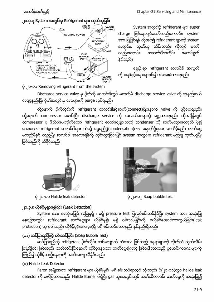
(F) Refrigerant quantity or level.
(G) Water flow rates. (Adjust the pumps to provide design flow and measuring the pressure drop o o o o . o o o determine if internal scaling is occurring.)
(H) Expansion valve operation (for reciprocating compressor systems).
၂၁.၇.၁ Recommended Chiller Monitoring Points Table 21-3 recommended chiller-monitoring points as per ASHRAE Standard 147
Chilled Water (or other secondary
coolant)
Flow
Condenser Water
Flow
Inlet Pressure Inlet Pressure
Inlet Temperature Inlet Temperature
Outlet Pressure Outlet Pressure
Outlet Temperature Outlet Temperature
Evaporator Refrigerant Pressure
Condenser Refrigerant Pressure
Refrigerant Temp. Refrigerant Temperature
Oil
Level
Refrigerant
Level
Pressure Compressor Discharge Temp.
Temperature Compressor Suction Temp.
Vibration Levels PPM Refrigerant Monitor Level
Purge Exhaust Time
Logs Date and Time Data
Discharge Count Signature of Reviewer
Ambient Temperatures
Dry Bulb Ambient Temperatures
Amps Per Phase
Wet Bulb Volts Per Phase
၂၁-၁၅ Centrifugal chiller overhaul ၂၁-၁၆ Rotary screw chiller overhaul

႔ Chapter-21 Servicing and Maintenance
21-17
၂၁.၇.၂ Periodic Maintenance Chiller Log Periodic Maintenance Chiller Log
Main Tab Run Time
15 min 30 min 1 hr Chiller Mode Evap Ent/Lvg Water Temp Cond Ent/Lvg Water Temp Active Chilled Water Setpoint (°F) Average Line Current (%RLA) Active Current Limit Setpoint (%RLA) Software Type Software Version
Evaporator Evap Entering Water Temperature (°F) Evap Leaving Water Temperature (°F) Evap Sat Refrigerant Temp (°F) Evap Refrigerant Pressure (psia) Evap Approach Temp (°F) Evap Water Flow Switch Status Expansion Valve Position (%) Expansion Valve Position Steps Evap Rfgt Liquid Level (in)
Condenser Cond Entering Water Temperature (°F) Cond Leaving Water Temperature (°F) Cond Sat Refrigerant Temp (°F) Cond Refrigerant Pressure (psia) Cond Approach Temp (°F) Cond Water Flow Switch Status Cond Head Pressure Ctrl Command (%)
Compressor Compressor Starts Compressor Run Time System Refrigerant Diff Pressure (psid) Oil Pressure (psia) Compressor Refrigerant Discharge Temp (°F) Discharge Superheat (°F) % RLA L1 L2 L3 (%) Amps L1 L2 L3 (Amps) Volts AB BC CA

႔
21-18
၂၁.၇.၃ Maintenance Requirements for YK Chiller Y

႔ Chapter-21 Servicing and Maintenance
21-19
၂၁.၇.၄Maintenance Requirements for YT Chiller Y

႔
21-20
၂၁.၇.၅ Maintenance Requirements for YR Chiller Y o w

႔ Chapter-21 Servicing and Maintenance
21-21
၂၁.၇.၆ Maintenance Requirements for YS Chiller Y o w

႔
21-22
၂၁.၇.၇ Maintenance Schedule Y YK
maintenance schedule Table 21-4 maintenance schedule
Maintenance Hours of Operation
5000
1000
0
1500
0
2000
0
2500
0
3000
0
3500
0
4000
0
4500
0
5000
0
Change Compressor Oil x x x x x x x x x x Change Oil Filter Elements x x x x x x x x x x Change Dehydrator Filter Driers x x x x x x x x x x Oil Analysis x x x x x x x x x x Condenser Tubes Cleaning x x x x x x x x x x
Thrust Bearing and Proximity Sensor x x
Replacement of Shaft Seal x x Revarnish of Motor Stator Windings & Bearings
x x
Pressure Test x x Eddy Current Testing of Condenser Tubes
x x
Inspection/Cleaning Cooler Tubes x x
Inspection/Overhaul of Compressor x Vibration Analysis x x x x x x x x x x
၂၁.၇.၈ Tube Cleaning
၂၁-၁၇ Tube cleaning ၂၁-၁၈ Tube cleaning
၂၁.၇.၉ Annual Shutdown Scope of work for annual shutdown and condenser tube cleaning (၁) To dismantle and replace oil filter, filter driers and O ring.
(၂) To drain out old compressor oil and recharge with new oil.
(၃) To megger the compressor motor windings.

႔ Chapter-21 Servicing and Maintenance
21-23
(၄) To check and tighten control wires.
(၅) To drain out water from condenser.
(၆) To remove condenser water box cover (non piping end).
(၇) To clean the tubes by using nylon brushes.
(၈) To paint with anti rust paint at the internal surface of the water box.
(၉) To replace water box gasket.
(၁၀) To fix back the cover and fill in water.
(၁၁) Re-commission the chiller.
၂၁.၈ Long Term Maintenance (၁) ၅ Eddy current (electro-
၂ ႔ ၃ Tube crack) tube (thinning)
(၂) o o rotating component ၅ o ၅ centrifugal compressor impeller ႔ w o o o o o o sea gasket
(၃) Component
(၄) engine-drive) vapor compression cycle chiller electric-drive) chiller ၍
၂၁.၉ Overhaul overhaul (scope of work) ၁ To deliver transfer unit to site
၂ To transfer the refrigerant out from the chiller to the recovery unit.
၃ To isolate the chiller power supply.
၄ To disconnect Compressor Motor power cable
၅ To erect the hoisting framework and equipments.
၆ To hoist down the Compressor Motor from the chiller mounting and send to workshop for overhaul
၇ To hoist down the Compressor to plant room floor level
၈ To dismantle the Compressor for inspection, overhaul and replace the overhaul parts.
၉ To assemble back the Compressor and check all the tolerance base on spec.

႔
21-24
၁၀ Installed the Compressor back on to the chiller after overhaul
၁၁ To deliver the Compressor Motor from workshop to site after Compressor Motor overhaul
၁၂ Install the Compressor Motor onto the chiller
၁၃ Re-connect the Compressor Motor cable
၁၄ To flush, clean the oil pump and oil line with nitrogen
၁၅ To flush the entire system with nitrogen
၁၆ To pressure test the chiller with nitrogen gas to 150 psig and perform leak check and hold the pressure for overnight to ensure system tightness.
၁၇ To vacuum the system to requirement standard
၁၈ To charge in refrigerant into the system.
၁၉ To replace the Compressor oils and all the filters
၂၀ To dismantle the Condenser and Cooler water box
၂၁ To perform Condenser and Cooler tubes cleaning
၂၂ To flush clean the Condenser and Cooler tubes with water
၂၃ To perform Eddy Current Test to determine the Condenser and Cooler tubes wall thickness
၂၄ To cover the Condenser and Cooler water box
၂၅ o ‘ON ow o o o o
၂၆ To re-commission the chiller.
၂၁.၁၀ Troubleshooting
၂၁.၁၀.၁ Detecting and Correcting Problems R o - o o ႕ ႔
o (possible causes) (corrective measures) ႆ (troubleshooting) test procedure)
Table 21-5 Trouble Possible Cause Corrective Measure
High condensing pressure.
Inlet water warm. Purge air from condenser Air on non-condensable gas in system.
Increase quantity of condensing water.
Insufficient water flowing through condenser.
Increase quantity of water.
Condenser tubes clogged or scaled. Clean condenser water tubes. Too much liquid in receiver, condenser tubes submerged in liquid refrigerant.
Draw off liquid into service cylinder.
Low condensing pressure.
Too much water flowing through condenser.
Reduce quantity of water.

႔ Chapter-21 Servicing and Maintenance
21-25
Water too cold. Reduce quantity of water.
Liquid refrigerant flooding back from evaporator.
Change expansion valve adjustment, examine fastening of thermal bulb.
Leaky discharge valve. Remove head, examine valves. Replace any found defective.
Frosting or sweating of a liquid line.
Refrigerant line restriction. Check for partially closed stop valve, or stuck solenoid valve.
System low on refrigerant. Check for leaks, add refrigerant. High suction pressure.
Overfeeding of expansion valve. Regulate expansion valve, check bulb attachment.
Compressor crankcase sweating
Leaky suction valve. Remove head, examine valve and replace if worn.
Low suction pressure.
Restricted liquid line and expansion valve or suction screens.
Rump down, remove, examine and clean screens,
Insufficient refrigerant in system. Check for refrigerant storage.
Too much oil circulating in system. Check for too much oil in circulation. Remove oil.
Improper adjustment of expansion valves
Adjust valve to give more flow.
Expansion valve power element dead or weak
Replace expansion valve power element.
Compressor short cycles on low- pressure control.
Low refrigerant charge. Locate and repair leaks. Charge refrigerant.
Thermal expansion valve not feeding properly.
Adjust, repair or replace thermal expansion valve.
a. Dirty strainers. a. Clean strainers. b. Moisture frozen in orifice or orifice plugged with dirt.
b. Remove moisture or dirt (use system dehydrator).
c. Power element dead or weak c. Replace power element. Water flow through evaporators restricted or stopped. Evaporator coils plugged, dirty, or clogged with frost.
Remove restriction. Check water flow. Clean coils or tubes.
Defective low-pressure control switch.
Repair or replace low-pressure control switch.
Compressor runs continuously.
Shortage of refrigerant. Repair leak and recharge system. Leaking discharge valves. Replace discharge valves.
Compressor short cycles on high-
Insufficient water flowing through condenser, clogged condenser.
Determine if water has been turned off. Check for scaled or fouled

႔
21-26
pressure control switch.
condenser. Defective high-pressure control switch.
Repair or replace high-pressure control switch.
Compressor will not run.
Seized compressor. Repair or replace compressor. Cut-in point of low-pressure control switch too high.
Set L. P. control switch to cut-in at correct pressure.
High-pressure control switch does not cut-in.
Check discharge pressure and reset P. H. control switch.
1 .Defective switch. 1. Repair or replace switch. 2. Electric power cut off. 2. Check power supply. 3. Service or disconnect switch open.
3.Close switches.
4. Fuses blown. 4. Test fuses and renew if necessary.
5. Over-load relays tripped. 5. Re-set relays and find cause of overload.
6. Check voltage (should be within 10 percent of nameplate rating).
6. Low voltage. 7. Repair or replace motor.
8. Close switch manually to test power supply. If OK, check control circuit including temperature and pressure controls.
7. Electrical motor in trouble. 9. Check oil level in crankcase. Check oil pump pressure.
8. Trouble in starting switch or control circuit.
9. Compressor motor stopped by oil pressure differential switch.
Decreased capacity of the compressor.
High vapor superheat. Adjust or replace expansion valve.
Sudden loss of oil from crankcase.
Liquid refrigerant slugging back to compressor crank case.
Adjust or replace expansion valve.
Capacity reduction system falls to unload cylinders.
Hand operating stem of capacity control valve not turned to automatic position.
Set hand operating stem to automatic position.
Compressor continues to operate at full or partial load.
Pressure regulating valve not opening.
Adjust or repair pressure regulating valve.
႔ Chapter-21 Servicing and Maintenance
21-27
Capacity reduction system fails to load cylinders.
Broken or leaking oil tube between pump and power element.
Repair leak.
Low discharge pressure with high suction pressure.
Discharge relief valve leaking back to the suction side.
Replace relief valve.
Compressor continues to operate unloaded.
Pressure regulating valve not closing.
Adjust or repair pressure regulating valve.
Compressor oil brownish in color
Copper plating caused by moisture in the system.
Change filter drier, or dehydrator.
Compressor oil gray or metallic.
Compressor bearing wear or piston scoring.
Replace or overhaul compressor.
Compressor oil black Carbonization resulting from air in the system.
Remove air from system.
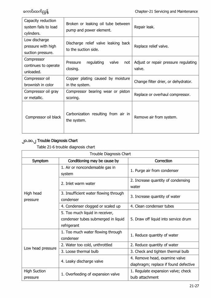
၂၁.၁၀.၂ Trouble Diagnosis Chart Table 21-6 trouble diagnosis chart
Trouble Diagnosis Chart Symptom Conditioning may be cause by Correction
High head pressure
1. Air or noncondensable gas in system
1. Purge air from condenser
2. Inlet warm water 2. Increase quantity of condensing water
3. Insufficient water flowing through condenser
3. Increase quantity of water
4. Condenser clogged or scaled up 4. Clean condenser tubes 5. Too much liquid in receiver, condenser tubes submerged in liquid refrigerant
5. Draw off liquid into service drum
Low head pressure
1. Too much water flowing through condenser
1. Reduce quantity of water
2. Water too cold, unthrottled 2. Reduce quantity of water 3. Loose thermal bulb 3. Check and tighten thermal bulb
4. Leaky discharge valve 4. Remove head, examine valve diaphragm; replace if found defective
High Suction pressure
1. Overfeeding of expansion valve 1. Regulate expansion valve; check bulb attachment

႔
21-28
2. Leaky suction or discharge valve 2. Remove head, examine valve disks; replace if worn
3. Hand bypass open or, if in use in place of expansion valve, open too much
3. Check hand bypass valve
Low suction pressure
1. Restricted liquid line and expansion valve or suction screens
1. Pump down, remove, examine, and clean screens
2. Insufficient gas in system 2. Check for gas shortage 3. Moisture in system, causing freezing of expansion valve
3. Wrap hot cloths around expansion valve and cycle through dehydrator
4. Too much oil circulating in system 4. Check for too much oil in circulation; remove oil
5. Improper adjustment of expansion valves
5. Adjust valves to give greater flow
6. 1/4-inch or more frost on evaporator coils
6. Defrost
Compressor short cycles (on high-pressure cutout)
1. Insufficient water flowing through condenser, clogged condenser cutout
1. Determine if water has been secured; check for scaled or fouled condenser
2. High-pressure cutout incorrectly set
2. Check setting of high-pressure cutout
3. System overcharged with refrigerant
3. High-pressure cutout may be tripping as a result of insufficient condenser capacity because tubes are submerged
Compressor short cycles (on low-pressure cutout)
1. Coils in refrigerators clogged with frost
1. Defrost coils
2. Liquid, suction, or expansion valve screens clogged
2. Pump down and clean screen
3. Thermal bulb on expansion valve has lost charge
3. Detach thermal bulb from suction line and hold in palm of one hand with the other hand gripping the suction line; if flooding through is observed, bulb has not lost its charge; if no flooding through is noticed, replace expansion valve
Compressor runs continuously
1. Shortage of refrigerants 1. Test refrigerant; if short of liquid, add amount necessary; test for leaks
2. Discharge valve leaks badly 2. Remove head of compressor, and repair or replace valves

႔ Chapter-21 Servicing and Maintenance
21-29
Compressor noisy
1. Vibration because not bolted to foundation rigidly
1. Bolt down rigidly
2. Too much oil in circulation, causing hydraulic knock
2. Check oil level
3. Slugging due to flooding back of refrigerant
3. Expansion valve open too wide, close; thermal bulb incorrectly placed or loose, check
4. Wear of parts such as piston pins, bearings, etc.
4. Determine location of cause; repair or replace compressor
5. Flywheel loose 5. Check key, tighten flywheel nut
Compressor will not start
1. Overload tripped, fuses blown 1. Reset overload, replace fuses and examine for cause of condition
2. Switch out 2. Throw in switch
3. No charge of liquid in system operated by low-pressure control
3. With no liquid in system, there is insufficient pressure to throw in low-pressure control; recharge system with liquid; stop leaks
4. Dirt or foreign matter on control points of either high- or low-pressure cutouts
4. Check and clean points
Head gasket leaks 1. Head bolts stretched, or washers crushed
1. Examine gaskets, replace if necessary; tighten head bolts; replace washers
Cylinders and crankcase sweating
1. Too much oil in circulation; too much refrigerant in circulation
1. Examine for conditions of refrigerant and oil charge; correct anything wrong
2. Hand bypass valve open or, if in use in place of expansion valve, open too much
2. Check hand bypass valve
-End-