Embed Size (px)
Citation preview
Chapter 21 Fault Tree Analysis (FTA) 487
Chapter 21
Fault Tree Analysis (FTA)
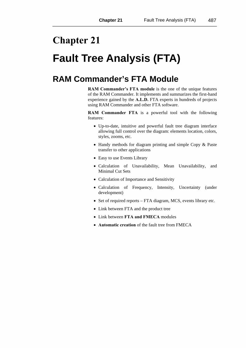
RAM Commander’s FTA Module RAM Commander’s FTA module is the one of the unique features of the RAM Commander. It implements and summarizes the first-hand experience gained by the A.L.D. FTA experts in hundreds of projects using RAM Commander and other FTA software.
RAM Commander FTA is a powerful tool with the following features:
• Up-to-date, intuitive and powerful fault tree diagram interface allowing full control over the diagram: elements location, colors, styles, zooms, etc.
• Handy methods for diagram printing and simple Copy & Paste transfer to other applications
• Easy to use Events Library
• Calculation of Unavailability, Mean Unavailability, and Minimal Cut Sets
• Calculation of Importance and Sensitivity
• Calculation of Frequency, Intensity, Uncertainty (under development)
• Set of required reports – FTA diagram, MCS, events library etc.
• Link between FTA and the product tree
• Link between FTA and FMECA modules
• Automatic creation of the fault tree from FMECA
488 RAM Commander User’s Guide
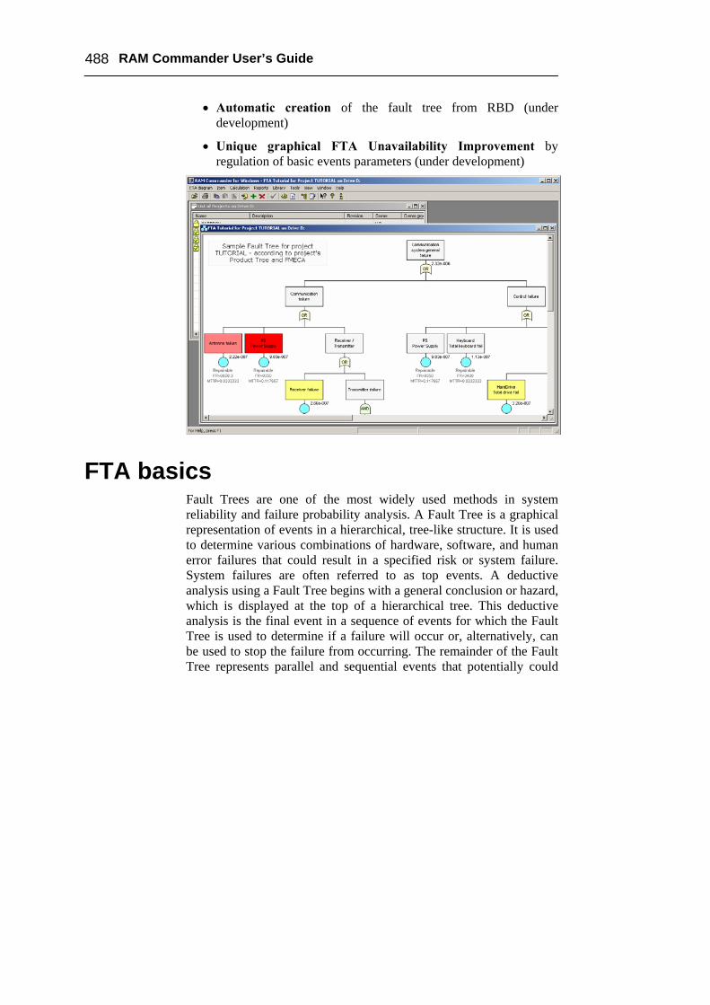
• Automatic creation of the fault tree from RBD (under development)
• Unique graphical FTA Unavailability Improvement by regulation of basic events parameters (under development)
FTA basics Fault Trees are one of the most widely used methods in system reliability and failure probability analysis. A Fault Tree is a graphical representation of events in a hierarchical, tree-like structure. It is used to determine various combinations of hardware, software, and human error failures that could result in a specified risk or system failure. System failures are often referred to as top events. A deductive analysis using a Fault Tree begins with a general conclusion or hazard, which is displayed at the top of a hierarchical tree. This deductive analysis is the final event in a sequence of events for which the Fault Tree is used to determine if a failure will occur or, alternatively, can be used to stop the failure from occurring. The remainder of the Fault Tree represents parallel and sequential events that potentially could
Chapter 21 Fault Tree Analysis (FTA) 489
cause the conclusion or hazard to occur and the probability of this conclusion.
A fault tree is a graphical representation of a logical structure representing undesired events ("failures") and their causes. You create the logical structure by using gates and represent undesired events by using basic events. Reliability parameters are assigned to the basic events. Widely used in system reliability studies, fault tree analysis offers the ability to focus on an event of importance, such as a highly critical safety issue, and work to minimize its occurrence or consequence. The probability of the top-level event can then be determined by using mathematical techniques. The resulting fault tree diagram is a graphical representation of the chain of events in your system or process, built using events and logical gate configurations.
The main purpose of Fault Tree Analysis is to evaluate the probability of the top event using state-of-the-art analytical and/or statistical methods. These calculations involve system quantitative reliability and maintainability data, such as failure probability, failure rate, expected failure, down time, repair rate, etc.
Two types of analysis can be conducted using Fault Trees:
• Qualitative Analysis: performed by means of Minimal Cut Sets (MCS) building
• Quantitative Analysis: calculating the Absolute probabilities, i.e. the probabilities of system failures
Definition: A Cut Set is a collection of basic events that if all its events occur, the fault trees top event is guaranteed to occur.
A Minimal Cut Set is such Cut Set that, if any basic event is removed from the set, the remaining events collectively are no longer a cut set. A cut set that includes some other sets is not a minimal cut set.
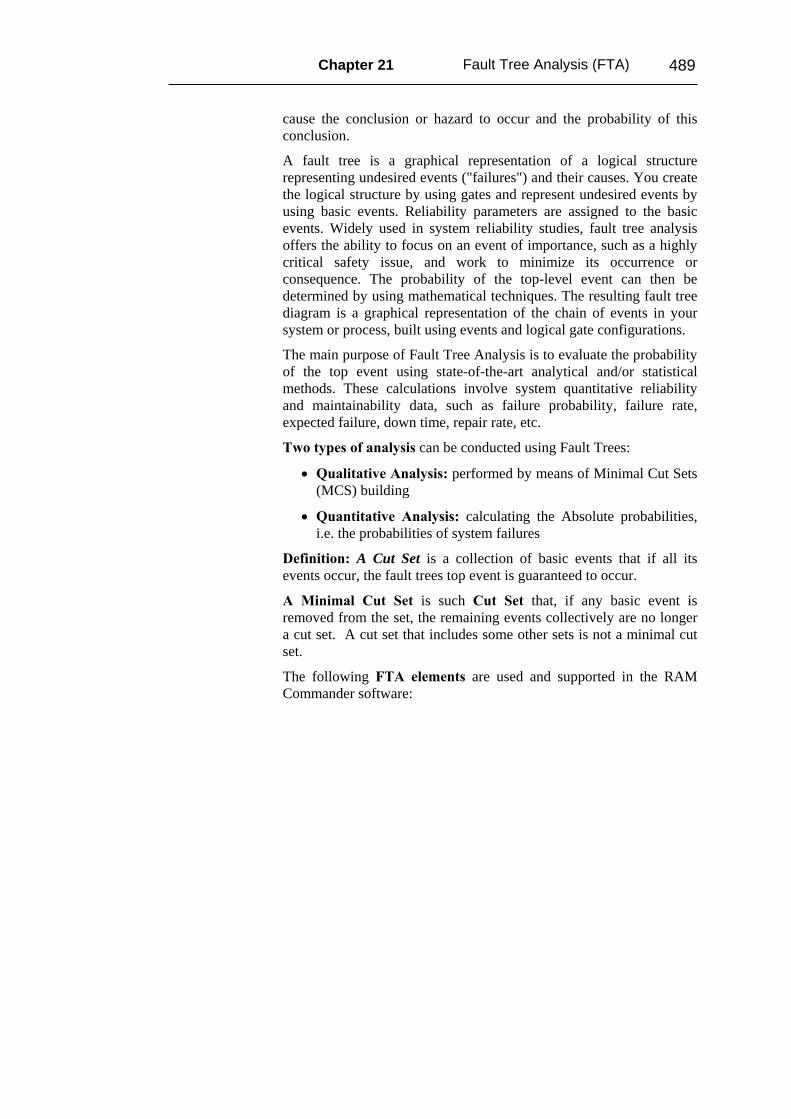
The following FTA elements are used and supported in the RAM Commander software:
490 RAM Commander User’s Guide
OR gate - output event occurs if any of the input events occurs.
AND gate - output event occurs only when all the input events occurs simultaneously.
NAND gate – NOT AND operation
NOR gate – NOT OR operation
XOR gate – Exclusive OR operation
K-out-of-N gate - output event occurs if K or more of the input events occurs
Chapter 21 Fault Tree Analysis (FTA) 491
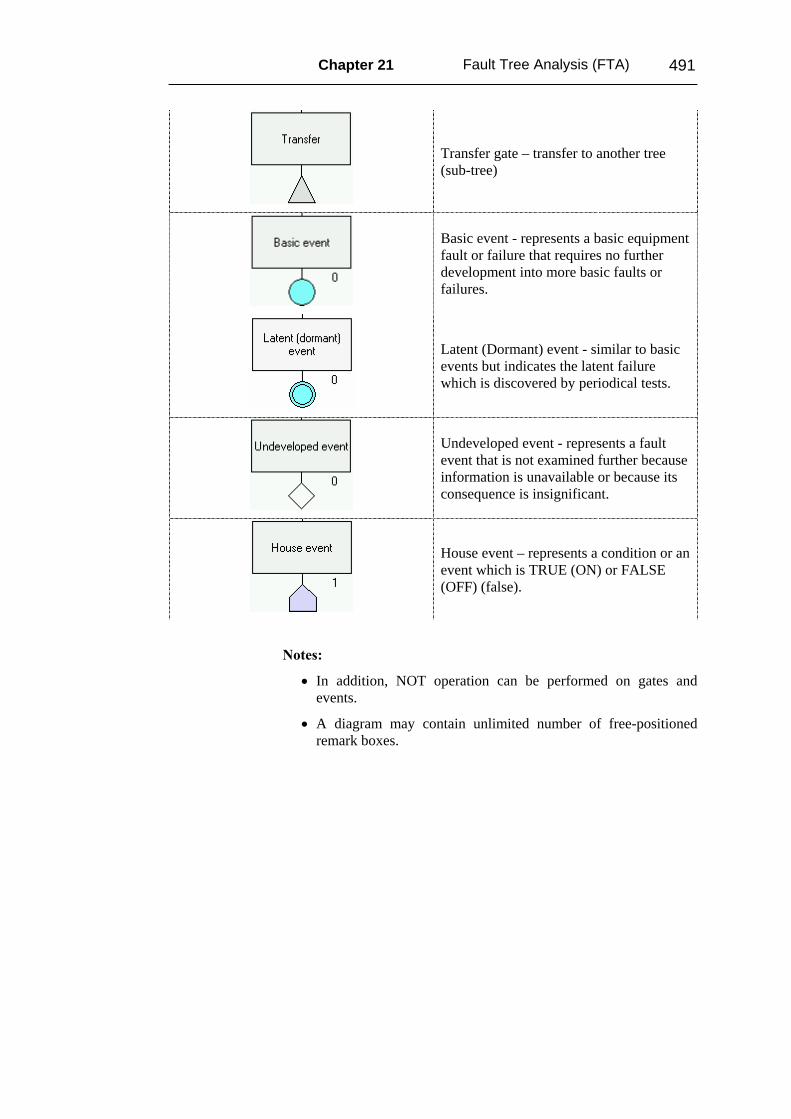
Transfer gate – transfer to another tree (sub-tree)
Basic event - represents a basic equipment fault or failure that requires no further development into more basic faults or failures.
Latent (Dormant) event - similar to basic events but indicates the latent failure which is discovered by periodical tests.
Undeveloped event - represents a fault event that is not examined further because information is unavailable or because its consequence is insignificant.
House event – represents a condition or an event which is TRUE (ON) or FALSE (OFF) (false).
Notes:
• In addition, NOT operation can be performed on gates and events.
• A diagram may contain unlimited number of free-positioned remark boxes.
492 RAM Commander User’s Guide
Using FTA module
FTA module initiation To enter the RAM Commander FTA module, do one of the following:
• In the list of projects, select a project, right-click and choose FTA from the pop-up menu.
• Open a project and choose FTA from the Modules menu.
• Open a project, click Modules at the left button-bar, and click the FTA button.
The FTA module screen is displayed with a list of existing FTA diagrams.
Notes:
• There can be an unlimited number of diagrams in the project.
• Diagrams can be connected to each other using transfer gates.
• All diagrams in the same project use the same basic events library.
To edit an existing diagram, select it in the list and click OK.
To create a new diagram, enter its name in the edit box and click OK. The FTA diagram screen is displayed.
Chapter 21 Fault Tree Analysis (FTA) 493
Sample Tree
AND5.76e-005
RAM Commandersample Fault Tree
Power Failure
0.04
Connection failure
0.01
Software failure
OR
OS failureOperating system
failure
0.0247
Application failureApplication software
failure
0.1
Operator failuresTransfer to Operator
failures subtree
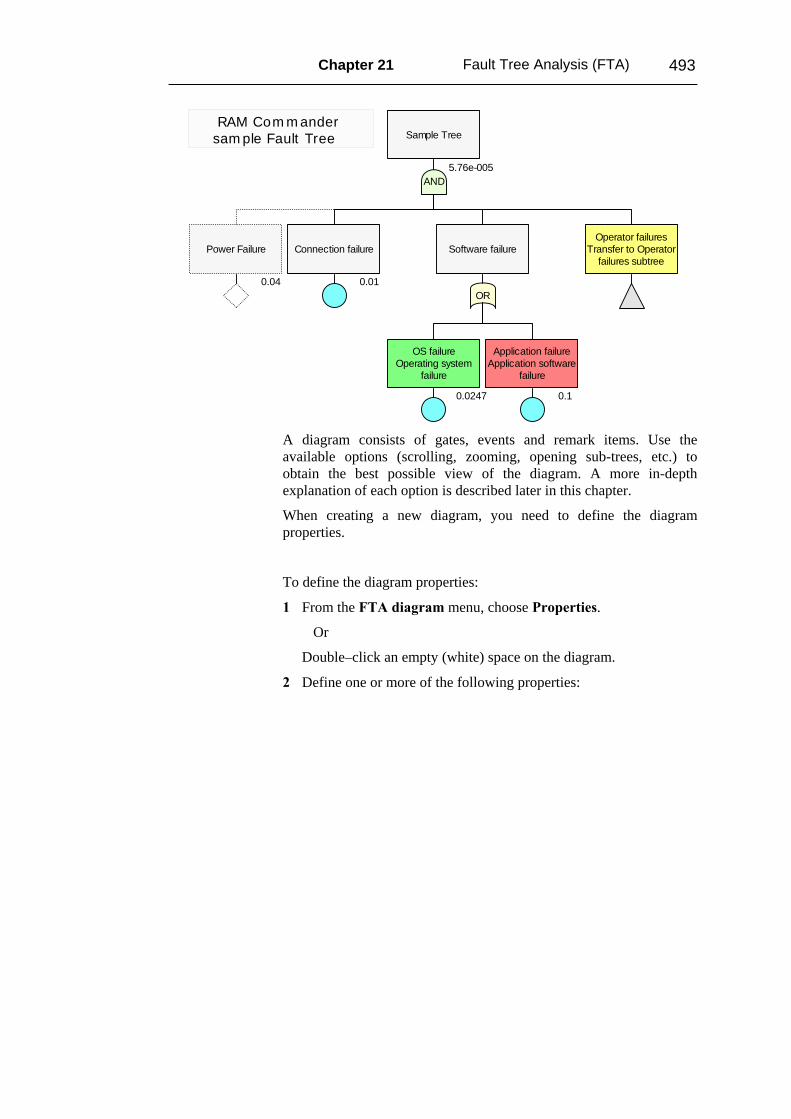
A diagram consists of gates, events and remark items. Use the available options (scrolling, zooming, opening sub-trees, etc.) to obtain the best possible view of the diagram. A more in-depth explanation of each option is described later in this chapter.
When creating a new diagram, you need to define the diagram properties.
To define the diagram properties:
1 From the FTA diagram menu, choose Properties.
Or
Double–click an empty (white) space on the diagram.
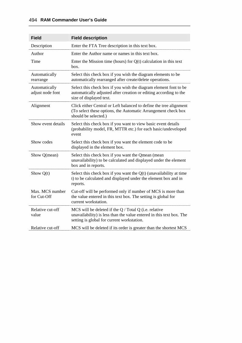
2 Define one or more of the following properties:
494 RAM Commander User’s Guide
Field Field description
Description Enter the FTA Tree description in this text box.
Author Enter the Author name or names in this text box.
Time Enter the Mission time (hours) for Q(t) calculation in this text box.
Automatically rearrange
Select this check box if you wish the diagram elements to be automatically rearranged after create/delete operations.
Automatically adjust node font
Select this check box if you wish the diagram element font to be automatically adjusted after creation or editing according to the size of displayed text.
Alignment Click either Central or Left balanced to define the tree alignment (To select these options, the Automatic Arrangement check box should be selected.)
Show event details Select this check box if you want to view basic event details (probability model, FR, MTTR etc.) for each basic/undeveloped event
Show codes Select this check box if you want the element code to be displayed in the element box.
Show Q(mean) Select this check box if you want the Qmean (mean unavailability) to be calculated and displayed under the element box and in reports.
Show Q(t) Select this check box if you want the Q(t) (unavailability at time t) to be calculated and displayed under the element box and in reports.
Max. MCS number for Cut-Off
Cut-off will be performed only if number of MCS is more than the value entered in this text box. The setting is global for current workstation.
Relative cut-off value
MCS will be deleted if the Q / Total Q (i.e. relative unavailability) is less than the value entered in this text box. The setting is global for current workstation.
Relative cut-off MCS will be deleted if its order is greater than the shortest MCS

Chapter 21 Fault Tree Analysis (FTA) 495
Field Field description order order + specified value. The setting is global for current
workstation.
Sensitivity factor Sensitivity Factor is used for high and low unavailability values for Sensitivity calculation; the default value is 10. The setting is global for current workstation.
Having defined your FTA diagram properties, you can now start creating the FTA diagram.
FTA diagram building When a new diagram is opened, the tree top event is created. You can now start the tree building by adding successors (child items) to the top event.
To add a successor (child) to the tree element:
1 Select the tree element and then right-click. Choose Add Element from the pop-up menu.
OR
Select the tree element and press the F7 key.
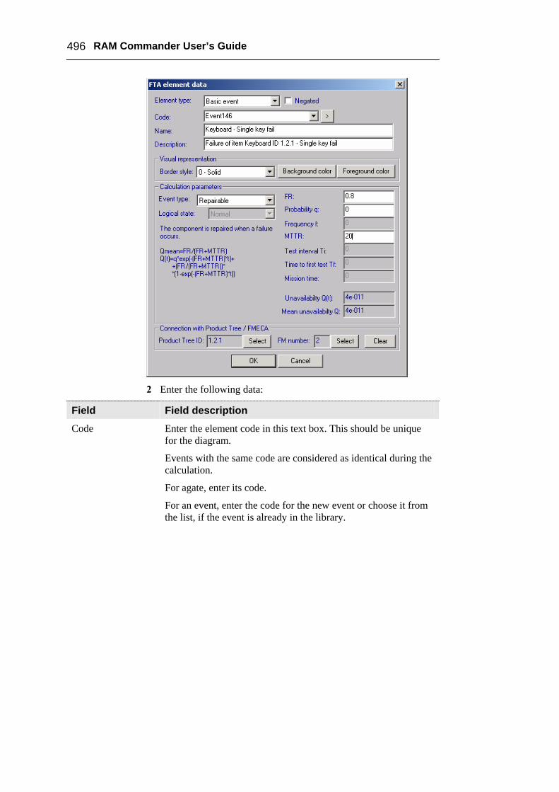
The FTA element data screen is displayed.
496 RAM Commander User’s Guide
2 Enter the following data:
Field Field description
Code Enter the element code in this text box. This should be unique for the diagram.
Events with the same code are considered as identical during the calculation.
For agate, enter its code.
For an event, enter the code for the new event or choose it from the list, if the event is already in the library.
Chapter 21 Fault Tree Analysis (FTA) 497
Field Field description
Name Enter the element name in this text box.
Description Enter a description for the element in this text box.
Negated Select this check box if you want the gate or event to be negated (NOT operation applied).
K Enter a value for K-out-of-N gate - K argument.
N Enter a value for the N for K-out-of-N gate (calculated automatically by the number of gate's children)
Border style Select a border style of the gate/event box (Solid, Dot, etc.) from the drop down list.
Background color Select a background color of the element from the color palette.
Font Select a font for the element code and name.
Foreground color Select a foreground color of the element from the color palette.
Event type Select an Event reliability model from the list (Probability, Frequency, Repaired, Unrepaired, etc.). See the calculation description for the formulas for each model.
Logical state Select a Logical state for House events from the drop-down list.
FR Select a Failure rate from the drop-down list (failures per million or trillion of hours, depending on project settings).
FR multiplier Enter a value for Failure Rate multiplier. (FR used in unavailability calculation is item FR * FR Multiplier.)
Probability q Enter a value for Probability q.
Frequency f Enter a value for Frequency F.
MTTR Enter a value in hours for MTTR (Mean Time To Repair).
Test interval Enter a value in hours for the Test interval (time between periodical tests).
Time to first test Enter a value in hours for Time to first test.
498 RAM Commander User’s Guide
Field Field description
Mission time Enter a value in hours for the Mission time.
Q(t) Enter a value for the Unavailability Q(t) - probability of failure at a given time point.
Q mean Enter a value for the Probability or long-term steady-state average unavailability, Q.
Tree ID For events, ID of linked element in Product Tree. This value cannot be changed.
FM number For events, number of FMECA Failure Mode of linked element in Product Tree. This value cannot be changed.
To edit tree element, double-click on it, or right–click on it and choose Edit from the pop-up menu. Data screen described above is displayed.
Possibility to set font for multiple FTA items
You may select several FTA elements (using Ctrl with mouse selection), then choose “Set font…” option from the Item menu and define the new font – it will be applied for all selected elements. Note: The successor automatically receives the Code equal to the predecessor’s code plus the number of successors. For example, if top event’s code is “AAA”, the predecessors receive codes “AAA-1”, “AAA-2”, etc. This is only a default value and can be changed by user.
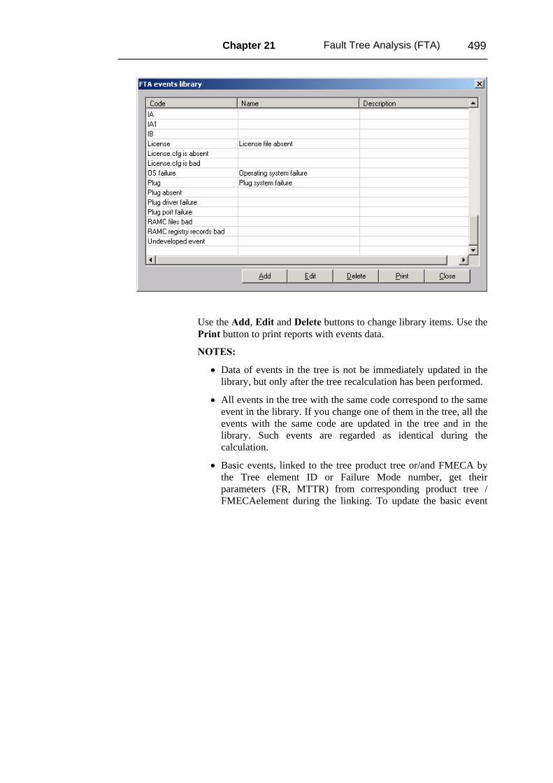
Events library All basic, undeveloped and house events that you assigned to the tree are added to the event library. In tree element item data screen, you may choose an event from the library by opening Code combo box or by clicking the “>button to the right of it.
If you want to edit or view the Events Library, choose Events from the Library menu.
Chapter 21 Fault Tree Analysis (FTA) 499
Use the Add, Edit and Delete buttons to change library items. Use the Print button to print reports with events data.
NOTES:
• Data of events in the tree is not be immediately updated in the library, but only after the tree recalculation has been performed.
• All events in the tree with the same code correspond to the same event in the library. If you change one of them in the tree, all the events with the same code are updated in the tree and in the library. Such events are regarded as identical during the calculation.
• Basic events, linked to the tree product tree or/and FMECA by the Tree element ID or Failure Mode number, get their parameters (FR, MTTR) from corresponding product tree / FMECAelement during the linking. To update the basic event
500 RAM Commander User’s Guide
data later on, choose Update events from RAM & FMECA from the Library menu.
Transfers Transfer gates are used to connect diagrams. With Transfer gates, a large diagram may be divided into smaller trees or a sub-tree can be inserted into the same or different tree multiple times.
You can perform the following actions with Transfer gates:
• To open the sub-diagram, double-click the transfer gate in the diagram.
• To change the sub-tree under the transfer, select the transfer gate, right-click and choose Edit from the pop-up menu. In the Edit dialog box, click Select and choose the desired sub-tree from the list.
• To delete the transfer and insert the whole sub-tree into the current tree, select the transfer gate, right-click and choose Expand sub-tree from pop-up menu.
• To divide a part of a large tree into sub-tree, select tree element you wish to be a top gate of the sub-tree, right-click and choose Transfer branch to sub-tree from the pop-up menu. The Transfer gate and a new sub-tree are created.
Remarks Remarks clarify the fault tree diagram by allowing you to add descriptive text and pictures.
To create a remark:
1. Select any tree element (gate or event), right-click.
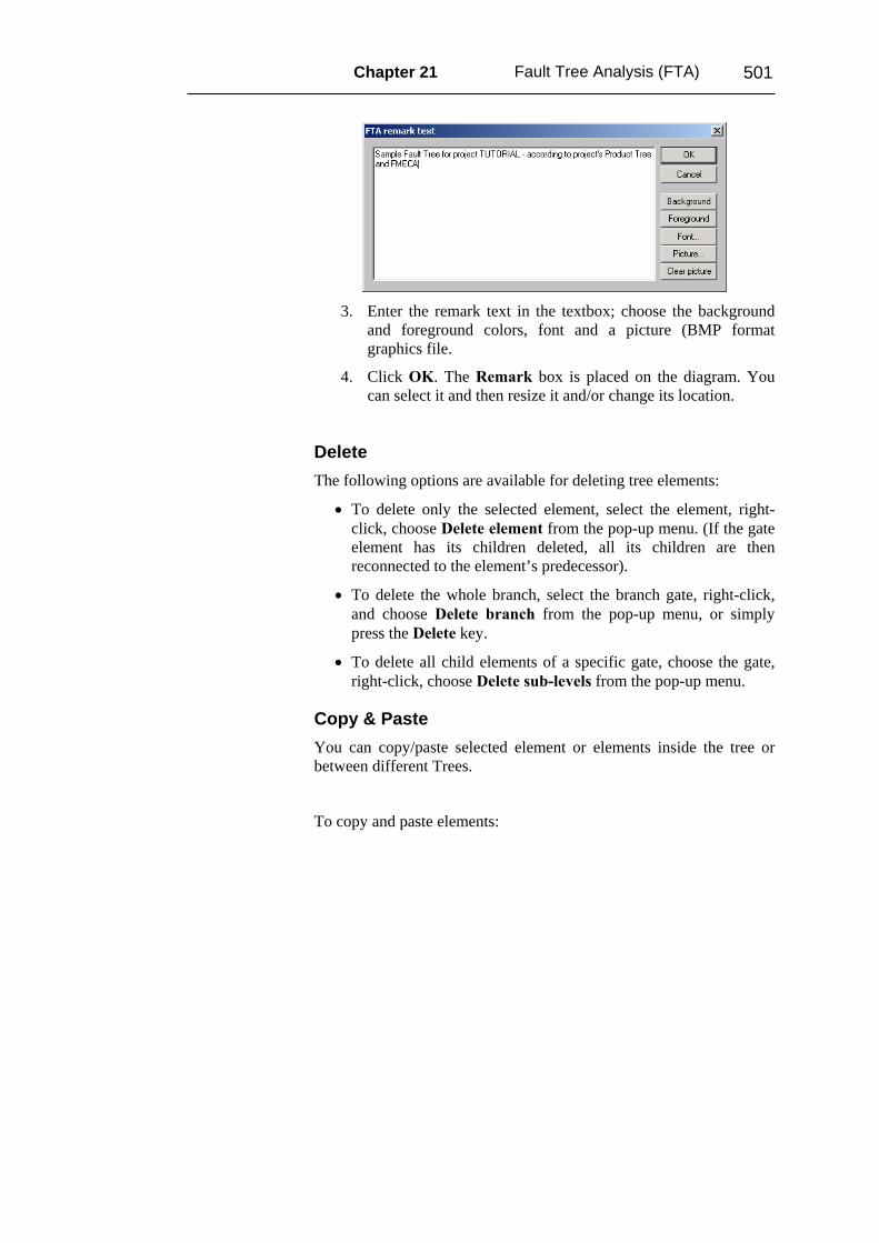
2. Choose Add remark from the pop-up menu. The Remark dialog box appears.
Chapter 21 Fault Tree Analysis (FTA) 501
3. Enter the remark text in the textbox; choose the background
and foreground colors, font and a picture (BMP format graphics file.
4. Click OK. The Remark box is placed on the diagram. You can select it and then resize it and/or change its location.
Delete The following options are available for deleting tree elements:
• To delete only the selected element, select the element, right-click, choose Delete element from the pop-up menu. (If the gate element has its children deleted, all its children are then reconnected to the element’s predecessor).
• To delete the whole branch, select the branch gate, right-click, and choose Delete branch from the pop-up menu, or simply press the Delete key.
• To delete all child elements of a specific gate, choose the gate, right-click, choose Delete sub-levels from the pop-up menu.
Copy & Paste You can copy/paste selected element or elements inside the tree or between different Trees.
To copy and paste elements:
502 RAM Commander User’s Guide
1 Select the items and then
Choose Copy from the Item menu
Or
Press Ctrl+C
Or
Right-click and select Copy from the pop-up menu.
2 Choose a tree to insert the items.
3 Select the tree element (gate) which will be the predecessor of the copied elements and then
Choose Paste from the Item menu
Or
Press Ctrl+V
Or
Right-click and choose Paste from the pop-up menu.
Another Paste option (Special Paste) allows you to paste tree elements automatically by changing their codes. To use this option, perform steps 1 and 2 as described above. In step 3, choose Paste Special… instead of Paste. The dialog allowing for automatic changes of events and gates codes appears. Select the required options and press OK.
Export Diagram as Picture You can insert the FTA tree as a picture into another application (Word, Excel, PowerPoint, etc.).
To insert the FTA tree into another application:
1 Choose Export to Clipboard from the FTA menu. The diagram is moved to the Clipboard.
2 Open another application.

Chapter 21 Fault Tree Analysis (FTA) 503
3 Select where you want to paste the diagram and press Ctrl + V or choose Paste from the Edit menu. The diagram is copied into the application.
Export FTA + all its sub trees to WMF (Windows Meta File)
Use the new option to export currently open Fault Tree (alone or with all its sub trees) to the Windows Metafile. You may later insert this file/files into another software – MS Word, Excel, Visio etc. The picture you get is not static but is a vector graphics set, which may be freely resized without quality loss and may be edited in MS Word, MS Excel, Visio etc.
Use FTA menu, “Export to File …” option to use this feature. Не получается
Print preview, Print, Zoom Use the FTA menu options to view print preview, print the tree, or zoom the diagram on the screen.
‘-‘ and ‘+’ keys on Numeric keyboard also act as Zoom in/Zoom out keys.
The following is a list of the FTA printing options in RAM Commander:
• Print: The whole tree is printed on a single piece of paper. Use this option when you have a normal size tree with no sub-trees.
• Print tree + sub-trees: The whole tree is printed as well as all of its sub- diagrams. Each tree is printed on a separate piece of paper. Use this option when you have a normal size tree with average size sub-trees.
• Print the selected branch only: Use this option to print only the selected branch without the rest of the tree. Branch parent gate should be selected.
504 RAM Commander User’s Guide
• Print + automatic separation to pages: Use this option when you have a large tree which doesn’t fit on a single page. RAM Commander automatically divides this large tree to smaller sub-trees in the most optimal way and prints them separately.
To adjust the Page Orientation for tree printing, select one of the following options from the FTA menu:
• Landscape
• Portrait
• Automatic: This is the default setting and allows RAM Commander to choose the most suitable page orientation for each diagram according to its layout.
Print FTA and all it’s sub-trees – do not print the same sub-tree multiple times
The automatic hierarchical printing is improved – now the same sub tree is printed only once, even if it is used several times in different transfer gates.
Analysis & Calculation To calculate the tree, choose
• MCS calculation from the Calculation menu.
Or
• MCS calculation for all gates from the Calculation menu.
Minimal Cut Sets calculation is performed, diagram Mean Unavailability (or Unavailability(t)) calculated and Minimal Cut Sets list generated.
The difference between the two calculation options (MCS calculation and MCS calculation for all gates) is that the first option calculates unavailability for top tree event only while the second option
Chapter 21 Fault Tree Analysis (FTA) 505
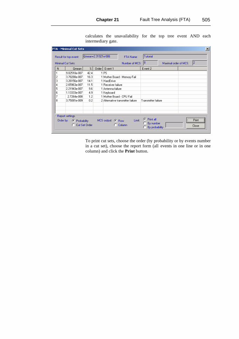
calculates the unavailability for the top tree event AND each intermediary gate.
To print cut sets, choose the order (by probability or by events number in a cut set), choose the report form (all events in one line or in one column) and click the Print button.
506 RAM Commander User’s Guide
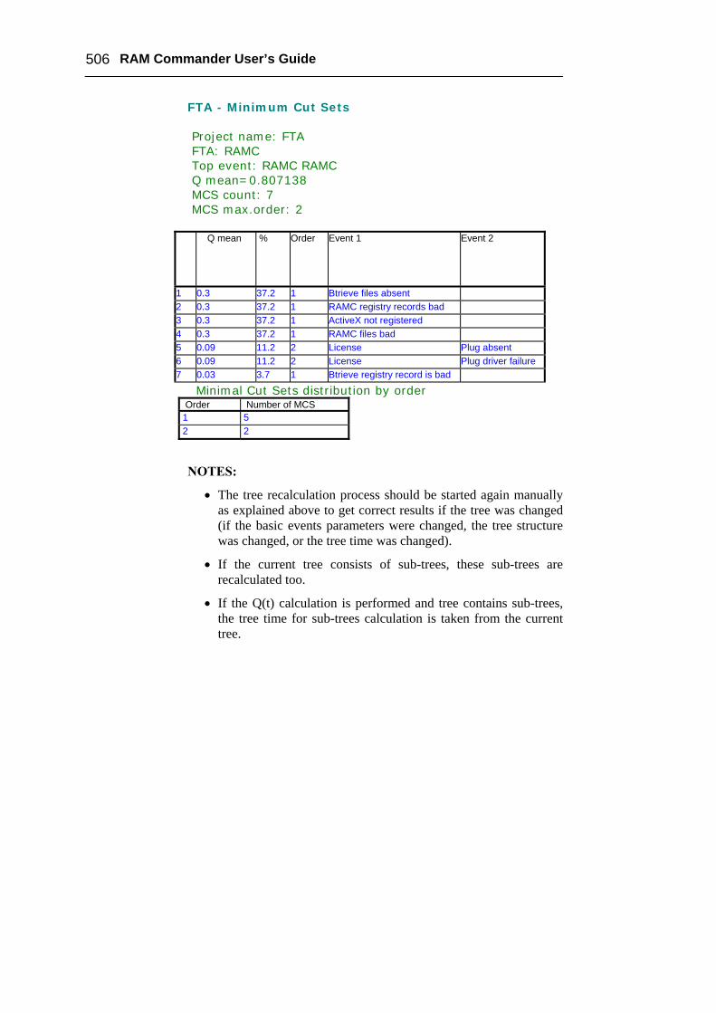
FTA - Minimum Cut Sets Project name: FTA FTA: RAMC Top event: RAMC RAMC Q mean=0.807138 MCS count: 7 MCS max.order: 2
Q mean % Order Event 1 Event 2
1 0.3 37.2 1 Btrieve files absent 2 0.3 37.2 1 RAMC registry records bad 3 0.3 37.2 1 ActiveX not registered 4 0.3 37.2 1 RAMC files bad 5 0.09 11.2 2 License Plug absent 6 0.09 11.2 2 License Plug driver failure 7 0.03 3.7 1 Btrieve registry record is bad
Minimal Cut Sets distribution by order Order Number of MCS 1 5 2 2
NOTES:
• The tree recalculation process should be started again manually as explained above to get correct results if the tree was changed (if the basic events parameters were changed, the tree structure was changed, or the tree time was changed).
• If the current tree consists of sub-trees, these sub-trees are recalculated too.
• If the Q(t) calculation is performed and tree contains sub-trees, the tree time for sub-trees calculation is taken from the current tree.
Chapter 21 Fault Tree Analysis (FTA) 507
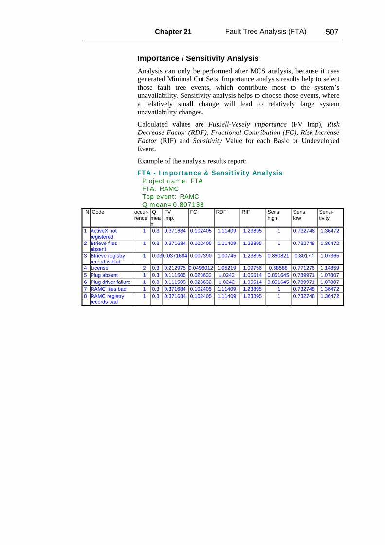
Importance / Sensitivity Analysis Analysis can only be performed after MCS analysis, because it uses generated Minimal Cut Sets. Importance analysis results help to select those fault tree events, which contribute most to the system’s unavailability. Sensitivity analysis helps to choose those events, where a relatively small change will lead to relatively large system unavailability changes.
Calculated values are Fussell-Vesely importance (FV Imp), Risk Decrease Factor (RDF), Fractional Contribution (FC), Risk Increase Factor (RIF) and Sensitivity Value for each Basic or Undeveloped Event.
Example of the analysis results report:
FTA - Importance & Sensitivity Analysis Project name: FTA FTA: RAMC Top event: RAMC Q mean=0.807138
N
Code
occur- rence
Q mean
FV Imp.
FC RDF RIF Sens. high
Sens. low
Sensi- tivity
1 ActiveX not registered
1 0.3 0.371684 0.102405 1.11409 1.23895 1 0.732748 1.36472
2 Btrieve files absent
1 0.3 0.371684 0.102405 1.11409 1.23895 1 0.732748 1.36472
3 Btrieve registry record is bad
1 0.03 0.0371684 0.007390 1.00745 1.23895 0.860821 0.80177 1.07365
4 License 2 0.3 0.212975 0.0496012 1.05219 1.09756 0.88588 0.771276 1.14859 5 Plug absent 1 0.3 0.111505 0.023632 1.0242 1.05514 0.851645 0.789971 1.07807 6 Plug driver failure 1 0.3 0.111505 0.023632 1.0242 1.05514 0.851645 0.789971 1.07807 7 RAMC files bad 1 0.3 0.371684 0.102405 1.11409 1.23895 1 0.732748 1.36472 8 RAMC registry
records bad 1 0.3 0.371684 0.102405 1.11409 1.23895 1 0.732748 1.36472
508 RAM Commander User’s Guide
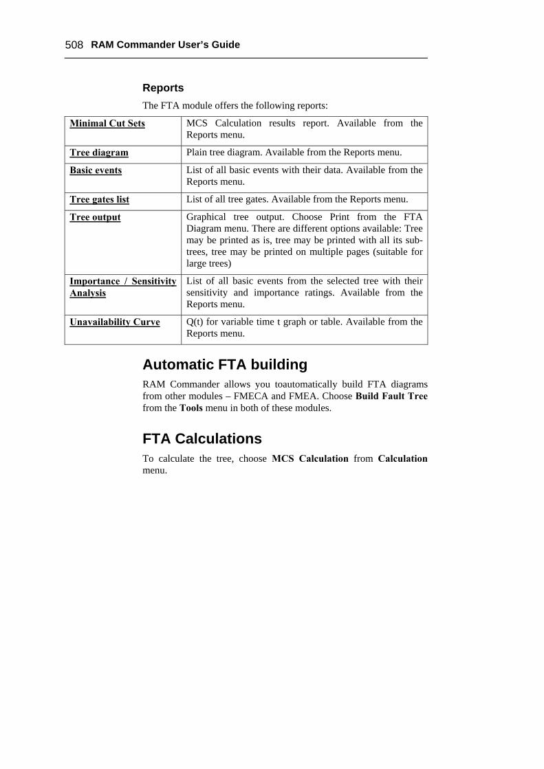
Reports The FTA module offers the following reports:
Minimal Cut Sets MCS Calculation results report. Available from the Reports menu.
Tree diagram Plain tree diagram. Available from the Reports menu.
Basic events List of all basic events with their data. Available from the Reports menu.
Tree gates list List of all tree gates. Available from the Reports menu.
Tree output Graphical tree output. Choose Print from the FTA Diagram menu. There are different options available: Tree may be printed as is, tree may be printed with all its sub-trees, tree may be printed on multiple pages (suitable for large trees)
Importance / Sensitivity Analysis
List of all basic events from the selected tree with their sensitivity and importance ratings. Available from the Reports menu.
Unavailability Curve Q(t) for variable time t graph or table. Available from the Reports menu.
Automatic FTA building RAM Commander allows you toautomatically build FTA diagrams from other modules – FMECA and FMEA. Choose Build Fault Tree from the Tools menu in both of these modules.
FTA Calculations To calculate the tree, choose MCS Calculation from Calculation menu.

Chapter 21 Fault Tree Analysis (FTA) 509
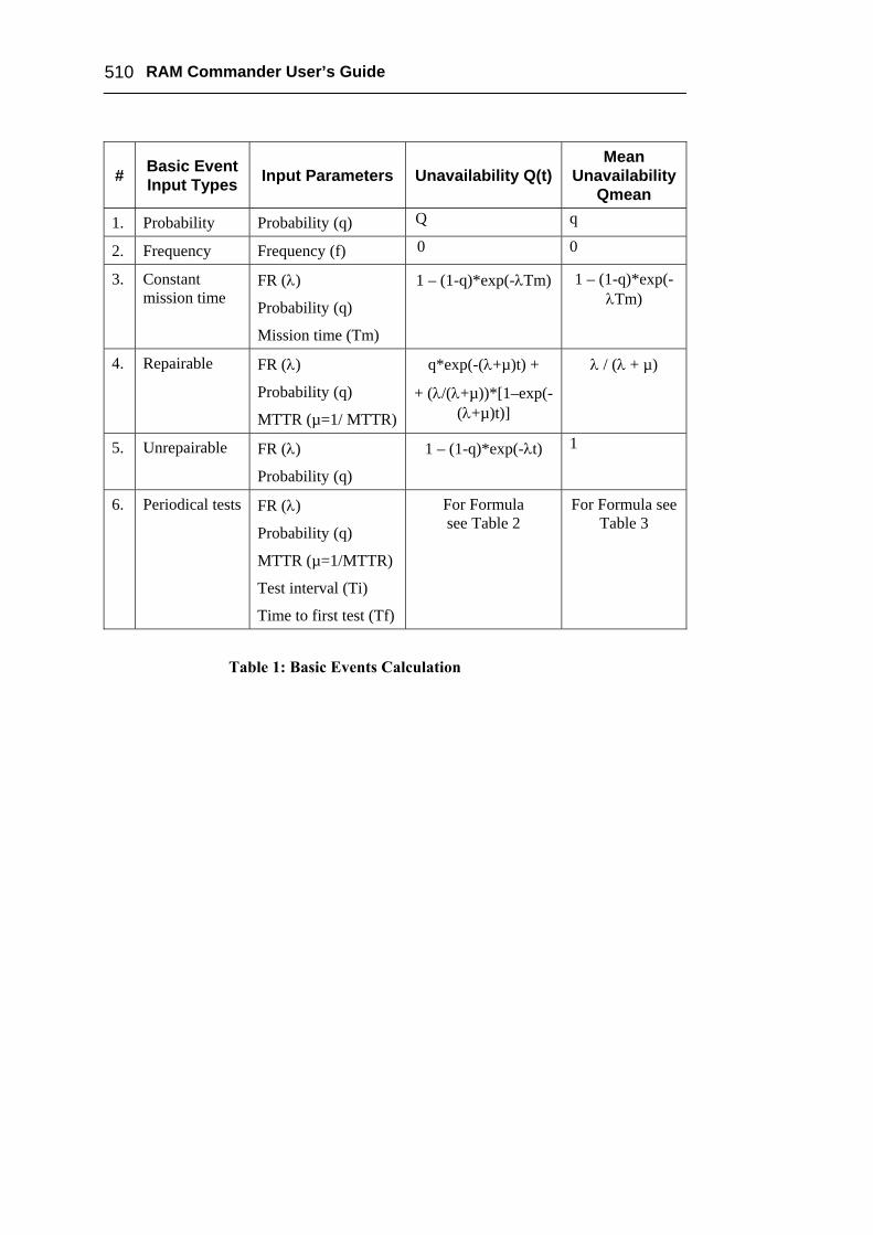
Basic Event Types RAM Commander allows several types of Basic Event reliability models: Probability, Frequency, Repaired, Unrepaired, and Periodical tests. The description of each model and calculation formulas are given below.
510 RAM Commander User’s Guide
# Basic Event Input Types Input Parameters Unavailability Q(t)
Mean Unavailability
Qmean
1. Probability Probability (q) Q q
2. Frequency Frequency (f) 0 0
3. Constant mission time
FR (λ)
Probability (q)
Mission time (Tm)
1 – (1-q)*exp(-λTm) 1 – (1-q)*exp(-λTm)
4. Repairable FR (λ)
Probability (q)
MTTR (µ=1/ MTTR)
q*exp(-(λ+µ)t) +
+ (λ/(λ+µ))*[1–exp(-(λ+µ)t)]
λ / (λ + µ)
5. Unrepairable FR (λ)
Probability (q)
1 – (1-q)*exp(-λt) 1
6. Periodical tests FR (λ)
Probability (q)
MTTR (µ=1/MTTR)
Test interval (Ti)
Time to first test (Tf)
For Formula see Table 2
For Formula see Table 3
Table 1: Basic Events Calculation
Chapter 21 Fault Tree Analysis (FTA) 511
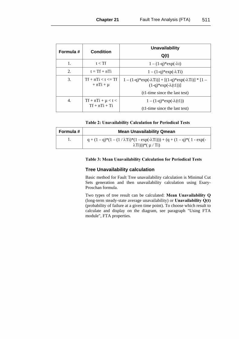
Formula # Condition Unavailability
Q(t)
1. t < Tf 1 – (1-q)*exp(-λt)
2. t = Tf + nTi 1 – (1-q)*exp(-λTi)
3. Tf + nTi < t <= Tf + nTi + µ
1 – (1-q)*exp(-λTi)] + [(1-q)*exp(-λTi)] * [1 – (1-q)*exp(-λ(t1))]
(t1-time since the last test)
4. Tf + nTi + µ < t < Tf + nTi + Ti
1 – (1-q)*exp(-λ(t1))
(t1-time since the last test)
Table 2: Unavailability Calculation for Periodical Tests
Formula # Mean Unavailability Qmean
1. q + (1 – q)*(1 – (1 / λTi)*(1 - exp(-λTi))) + (q + (1 – q)*( 1 - exp(-λTi)))*( µ / Ti)
Table 3: Mean Unavailability Calculation for Periodical Tests
Tree Unavailability calculation Basic method for Fault Tree unavailability calculation is Minimal Cut Sets generation and then unavailability calculation using Esary-Proschan formula.
Two types of tree result can be calculated: Mean Unavailability Q (long-term steady-state average unavailability) or Unavailability Q(t) (probability of failure at a given time point). To choose which result to calculate and display on the diagram, see paragraph "Using FTA module", FTA properties.
512 RAM Commander User’s Guide
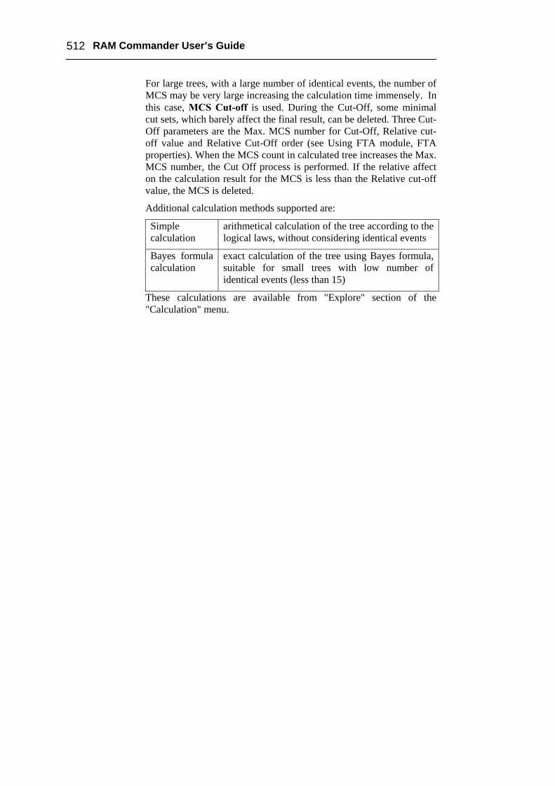
For large trees, with a large number of identical events, the number of MCS may be very large increasing the calculation time immensely. In this case, MCS Cut-off is used. During the Cut-Off, some minimal cut sets, which barely affect the final result, can be deleted. Three Cut-Off parameters are the Max. MCS number for Cut-Off, Relative cut-off value and Relative Cut-Off order (see Using FTA module, FTA properties). When the MCS count in calculated tree increases the Max. MCS number, the Cut Off process is performed. If the relative affect on the calculation result for the MCS is less than the Relative cut-off value, the MCS is deleted.
Additional calculation methods supported are:
Simple calculation
arithmetical calculation of the tree according to the logical laws, without considering identical events
Bayes formula calculation
exact calculation of the tree using Bayes formula, suitable for small trees with low number of identical events (less than 15)
These calculations are available from "Explore" section of the "Calculation" menu.
Chapter 21 Fault Tree Analysis (FTA) 513
Summary Fault Tree Analysis is acknowledged as a key tool for increasing safety. It is unique and indispensable in analyzing risks and determining various combinations of hardware, software, and human error failures that result in a specified risk or system failure. Fault tree analysis is useful both in designing new products/services and in dealing with identified problems in existing products/services. In the quality planning process, the analysis can be used to optimize process features and goals and to design for critical factors and human error. As part of process improvement, it can be used to help identify root causes of trouble and to design remedies and countermeasures.
The Fault Tree Analysis module is an advanced software tool with very convenient user interface and many of its useful features are not available in other FTA programs.

514 RAM Commander User’s Guide