Embed Size (px)
Citation preview
re-
a
u-
n
ed
.).al
-)if-ndd
of
re-eomofterthatd
a-hatP.
CHAPTER 20
SIGHT REDUCTION
BASIC PROCEDURES
2000. Computer Sight Reduction
The purely mathematical process of sight reduction isan ideal candidate for computerization, and a number ofdifferent hand-held calculators and computer programshave been developed to relieve the tedium of working outsights by tabular or mathematical methods. The civiliannavigator can choose from a wide variety of hand-heldcalculators and computer programs which require only theentry of the DR position, altitude and azimuth of the body,and GMT. It is not even necessary to know the name of thebody because the computer can figure out what it must bebased on the entered data. Calculators and computersprovide more accurate solutions than tabular andmathematical methods because they can be based on actualvalues rather than theoretical assumptions and do not haveinherent rounding errors.
U.S. Naval navigators have access to a program calledSTELLA (System To Estimate Latitude and Longitude As-tronomically; do not confuse with a commercial astronomyprogram with the same name). STELLA was developed bythe Astronomical Applications Department of the U.S. Na-val Observatory based on a Navy requirement. Thealgorithms used in STELLA provide an accuracy of onearc-second on the Earth’s surface, a distance of about 30meters. While this accuracy is far better than can be ob-tained using a sextant, it does support possible naval needsfor automated navigation systems based on celestial ob-jects. These algorithms take into account the oblateness ofthe Earth, movement of the vessel during sight-taking, andother factors not fully addressed by traditional methods.
STELLA can perform almanac functions, position up-dating/DR estimations, celestial body rise/set/transitcalculations, compass error calculations, sight planning,and sight reduction. On-line help and user’s guide are in-cluded, and it is a component of the Block III NAVSSI.Because STELLA logs all entered data for future reference,it is authorized to replace the Navy Navigation Workbook.STELLA is now an allowance list requirement for Navalships, and is available from:
SuperintendentU.S. Naval ObservatoryCode: AA/STELLA3450 Massachusetts Ave. NWWashington, DC, 20392-5420
or on the Navigator of the Navy Web site at
http://www.navigator.navy.mil/navigator/surface.html.
2001. Tabular Sight Reduction
The remainder of this chapter concentrates on sightduction using theNautical Almanacand Pub. No. 229,Sight Reduction Tables for Marine Navigation. The methodexplained here is only one of many methods of reducingsight. TheNautical Almanaccontains directions for solvingsights using its own concise sight reduction tables or calclators, along with examples for the current year
Reducing a celestial sight to obtain a line of positiousing the tables consists of six steps:
1. Correct the sextant altitude (hs) to obtain observaltitude (ho).
2. Determine the body’s GHA and declination (dec3. Select an assumed position (AP) and find its loc
hour angle (LHA).4. Compute altitude and azimuth for the AP.5. Compare the computed and observed altitudes.6. Plot the line of position.
The introduction to each volume ofPub. 229containsinformation: (1) discussing use of the publication for a variety of special celestial navigation techniques; (2discussing interpolation, explaining the double second dference interpolation required in some sight reductions, aproviding tables to facilitate the interpolation process; an(3) discussing the publication’s use in solving problemsgreat circle sailings. Prior to usingPub. 229, carefully readthis introductory material.
Celestial navigation involves determining a circulaline of position based on an observer’s distance from a clestial body’s geographic position (GP). Should thobserver determine both a body’s GP and his distance frthe GP, he would have enough information to plot a lineposition; he would be somewhere on a circle whose cenwas the GP and whose radius equaled his distance fromGP. That circle, from all points on which a body’s measurealtitude would be equal, is acircle of equal altitude. Thereis a direct proportionality between a body’s altitude as mesured by an observer and the distance of its GP from tobserver; the lower the altitude, the farther away the G
295
296 SIGHT REDUCTION
deefisn
fhengisis
d
tl tosP
tdpteth
cleal
ers,ofis
Therefore, when an observer measures a body’s altitude heobtains an indirect measure of the distance between himselfand the body’s GP. Sight reduction is the process of con-verting that indirect measurement into a line of position.
Sight reduction reduces the problem of scale to man-ageable size. Depending on a body’s altitude, its GP couldbe thousands of miles from the observer’s position. Thesize of a chart required to plot this large distance would beimpractical. To eliminate this problem, the navigator doesnot plot this line of position directly. Indeed, he does notplot the GP at all. Rather, he chooses anassumed position(AP) near, but usually not coincident with, his DR position.The navigator chooses the AP’s latitude and longitude tocorrespond to the entering arguments of LHA and latitudeused inPub. 229. FromPub. 229, the navigator computeswhat the body’s altitude would have been had it been mea-sured from the AP. This yields thecomputed altitude (hc).He then compares this computed value with theobservedaltitude (ho) obtained at his actual position. The differencebetween the computed and observed altitudes is directlyproportional to the distance between the circles of equal al-titude for the assumed position and the actual position.Pub.229also gives the direction from the GP to the AP. Havingselected the assumed position, calculated the distance be-tween the circles of equal altitude for that AP and his actualposition, and determined the direction from the assumedposition to the body’s GP, the navigator has enough infor-mation to plot a line of position (LOP).
To plot an LOP, plot the assumed position on either achart or a plotting sheet. From theSight Reduction Tables,determine: 1) the altitude of the body for a sight taken at theAP and 2) the direction from the AP to the GP. Then, deter-mine the difference between the body’s calculated altitudeat this AP and the body’s measured altitude. This differencerepresents the difference in radii between the equal altitudecircle passing through the AP and the equal altitude circlepassing through the actual position. Plot this differencefrom the AP either towards or away from the GP along theaxis between the AP and the GP. Finally, draw the circle ofequal altitude representing the circle with the body’s GP atthe center and with a radius equal to the distance betweenthe GP and the navigator’s actual position.
One final consideration simplifies the plotting of the equalaltitude circle. Recall that the GP is usually thousands of milesaway from the navigator’s position. The equal altitude circle’sradius, therefore, can be extremely large. Since this radius is solarge, the navigator can approximate the section close to his po-sition with a straight line drawn perpendicular to the lineconnecting the AP and the GP. This straight line approximationis good only for sights at relatively low altitudes. The higher thealtitude, the shorter the distance between the GP and the actualposition, and the smaller the circle of equal altitude. The shorterthis distance, the greater the inaccuracy introduced by thisapproximation.
2002. Selection of the Assumed Position (AP)
Use the following arguments when enteringPub. 229to compute altitude (hc) and azimuth:
1. Latitude (L)2. Declination (d or Dec.)3. Local hour angle (LHA)
Latitude and LHA are functions of the assumeposition. Select an AP longitude resulting in a whole degrof LHA and an AP latitude equal to that whole degree olatitude closest to the DR position. Selecting the AP in thmanner eliminates interpolation for LHA and latitude iPub. 229.
2003. Comparison of Computed and ObservedAltitudes
The difference between the computed altitude (hc) andthe observed altitude (ho) is thealtitude intercept (a).
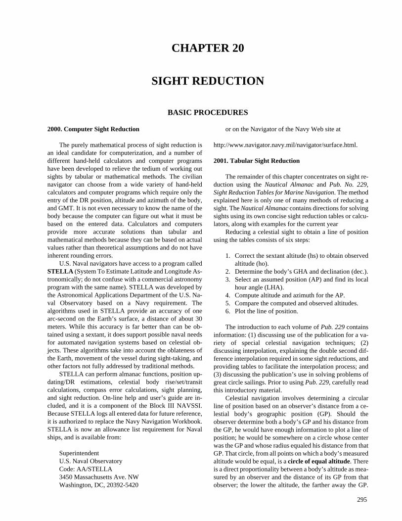
The altitude intercept is the difference in the length othe radii of the circles of equal altitude passing through tAP and the observer’s actual position. The position havithe greater altitude is on the circle of smaller radius andcloser to the observed body’s GP. In Figure 2004, the APshown on the inner circle. Therefore, hc is greater than ho.
Express the altitude intercept in nautical miles anlabel it T or A to indicate whether the line of position istoward or away from the GP, as measured from the AP.
A useful aid in remembering the relation between ho,hc, and the altitude intercept is:Ho Mo To for Ho MoreToward. Another is C-G-A:ComputedGreater Away,remembered asCoastGuardAcademy. In other words, if hois greater than hc, the line of position intersects a poinmeasured from the AP towards the GP a distance equathe altitude intercept. Draw the LOP through thiintersection point perpendicular to the axis between the Aand GP.
2004. Plotting the Line of Position
Plot the line of position as shown in Figure 2004. Plothe AP first; then plot the azimuth line from the AP towaror away from the GP. Then, measure the altitude intercealong this line. At the point on the azimuth line equal to thintercept distance, draw a line perpendicular to the azimuline. This perpendicular represents that section of the cirof equal altitude passing through the navigator’s actuposition. This is the line of position.
A navigator often takes sights of more than oncelestial body when determining a celestial fix. Afteplotting the lines of position from these several sightadvance the resulting LOP’s along the track to the timethe last sight and label the resulting fix with the time of thlast sight.
SIGHT REDUCTION 297
2)ed
ute
-ses
fis
of
d
the
-nt
2005. Sight Reduction Procedures
Just as it is important to understand the theory of sightreduction, it is also important to develop a practicalprocedure to reduce celestial sights consistently andaccurately. Sight reduction involves several consecutivesteps, the accuracy of each completely dependent on theaccuracy of the steps that went before.Sight reductiontables have, for the most part, reduced the mathematicsinvolved to simple addition and subtraction. However,careless errors will render even the most skillfullymeasured sights inaccurate. The navigator using tabular ormathematical techniques must work methodically to reducecareless errors.
Naval navigators will most likely use OPNAV 3530, U.S.Navy Navigation Workbook, which contains pre-formattedpages with “strip forms” to guide the navigator through sightreduction. A variety of commercially-produced forms are alsoavailable. Pick a form and learn its method thoroughly. Withfamiliarity will come increasing understanding, speed andaccuracy.
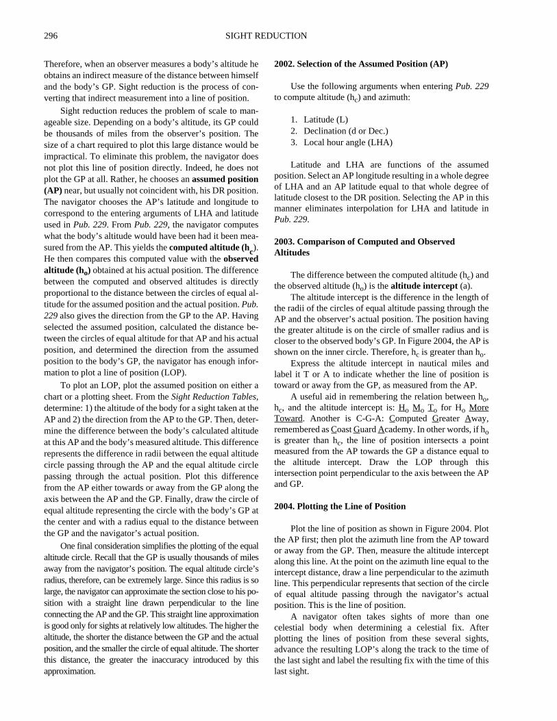
Figure2005representsa functionalandcompleteworksheetdesigned to ensure a methodical approach to any sight reductionproblem. The recommended procedure discussed below is notthe only one available; however, the navigator who uses it can beassured thathehasconsideredeverycorrection required toobtain
an accurate fix.
SECTION ONE consists of two parts: (1) Correctingsextant altitude to obtain apparent altitude; and (Correcting the apparent altitude to obtain the observaltitude.
Body: Enter the name of the body whose altitude yohave measured. If using the Sun or the Moon, indicawhich limb was measured.
Index Correction: This is determined by the characteristics of the individual sextant used. Chapter 16 discusdetermining its magnitude and algebraic sign.
Dip: The dip correction is a function of the height oeye of the observer. It is always negative; its magnitudedetermined from the Dip Table on the inside front covertheNautical Almanac.
Sum: Enter the algebraic sum of the dip correction anthe index correction.
Sextant Altitude: Enter the altitude of the bodymeasured by the sextant.
Apparent Altitude: Apply the correction determinedabove to the measured altitude and enter the result asapparent altitude.
Altitude Correction: Every observation requires an altitude correction. This correction is a function of the apparealtitude of the body. TheAlmanaccontains tables for determin-
Figure 2004. The basis for the line of position from a celestial observation.

298 SIGHT REDUCTION
SECTION ONE: OBSERVED ALTITUDE
Body _________________ _________________Index Correction _________________ _________________Dip (height of eye) _________________ _________________Sum _________________ _________________Sextant Altitude (hs) _________________ _________________
Apparent Altitude (ha) _________________ _________________
Altitude Correction _________________ _________________Mars or Venus Additional Correction _________________ _________________Additional Correction _________________ _________________Horizontal Parallax Correction _________________ _________________Moon Upper Limb Correction _________________ _________________Correction to Apparent Altitude (ha) _________________ _________________
Observed Altitude (ho) _________________ _________________
SECTION TWO: GMT TIME AND DATE
Date _________________ _________________DR Latitude _________________ _________________DR Longitude _________________ _________________Observation Time _________________ _________________Watch Error _________________ _________________Zone Time _________________ _________________Zone Description _________________ _________________Greenwich Mean Time _________________ _________________Date GMT _________________ _________________
SECTION THREE: LOCAL HOUR ANGLE AND DECLINATION
Tabulated GHA andv Correction Factor _________________ _________________GHA Increment _________________ _________________Sidereal Hour Angle (SHA) orv Correction _________________ _________________GHA _________________ _________________+ or - 360° if needed _________________ _________________Assumed Longitude (-W, +E) _________________ _________________Local Hour Angle (LHA) _________________ _________________Tabulated Declination andd Correction Factor _________________ _________________d Correction _________________ _________________True Declination _________________ _________________Assumed Latitude _________________ _________________
SECTION FOUR: ALTITUDE INTERCEPT AND AZIMUTH
Declination Increment andd Interpolation Factor _________________ _________________Computed Altitude (Tabulated) _________________ _________________Double Second Difference Correction _________________ _________________Total Correction _________________ _________________Computed Altitude (hc) _________________ _________________
Observed Altitude (ho) _________________ _________________
Altitude Intercept _________________ _________________Azimuth Angle _________________ _________________True Azimuth _________________ _________________
Figure 2005. Complete sight reduction form.
SIGHT REDUCTION 299
ethe
-
e-he,ne3)todd
on
orrcthee
or
e
to
tatonolen
heheason
ee
ly
he
ing these corrections. For the Sun, planets, and stars, these tablesare located on the inside front cover and facing page. For theMoon, these tables are located on the back inside cover and pre-ceding page.
Mars or Venus Additional Correction: As the nameimplies, this correction is applied to sights of Mars and Ve-nus. The correction is a function of the planet measured, thetime of year, and the apparent altitude. The inside front cov-er of theAlmanac lists these corrections.
Additional Correction: Enter this additional correctionfrom Table A-4 located at the front of theNautical Almanacwhen obtaining a sight under non-standard atmospheric tem-perature and pressure conditions. This correction is afunction of atmospheric pressure, temperature, and apparentaltitude.
Horizontal Parallax Correction: This correction is uniqueto reducing Moon sights. Obtain the H.P. correction value fromthe daily pages of theAlmanac. Enter the H.P correction table atthe back of theAlmanacwith this value. The H.P correction is afunction of the limb of the Moon used (upper or lower), the ap-parent altitude, and the H.P. correction factor. The H.P.correction is always added to the apparent altitude.
Moon Upper Limb Correction: Enter -30' for thiscorrection if the sight was of the upper limb of the Moon.
Correction to Apparent Altitude: Sum the altitudecorrection, the Mars or Venus additional correction, theadditional correction, the horizontal parallax correction, and theMoon’s upper limb correction. Be careful to determine and carrythe algebraic sign of the corrections and their sum correctly.Enter this sum as the correction to the apparent altitude.
Observed Altitude: Apply the Correction to ApparentAltitude algebraically to the apparent altitude. The result is theobserved altitude.
SECTION TWO determines the Greenwich Mean Time(GMT; referred to in theAlmanacs as Universal time or UT) andGMT date of the sight.
Date: Enter the local time zone date of the sight.DR Latitude: Enter the dead reckoning latitude of the
vessel.DR Longitude: Enter the dead reckoning longitude of the
vessel.Observation Time: Enter the local time of the sight as
recorded on the ship’s chronometer or other timepiece.Watch Error: Enter a correction for any known watch
error.Zone Time: Correct the observation time with watch
error to determine zone time.Zone Description:Enter the zone description of the time
zone indicatedby theDR longitude. If the longitude iswestof theGreenwich Meridian, the zone description is positive.Conversely, if the longitude is east of the Greenwich Meridian,the zone description is negative. The zone description representsthe correction necessary to convert local time to GreenwichMean Time.
Greenwich Mean Time:Add to the zone description the
zone time to determine Greenwich Mean Time.Date: Carefully evaluate the time correction applied abov
and determine if the correction has changed the date. EnterGMT date.
SECTION THREE determines two of the three arguments required to enterPub. 229: Local Hour Angle (LHA)and Declination. This section employs the principle that a clestial body’s LHA is the algebraic sum of its GreenwicHour Angle (GHA) and the observer’s longitude. Thereforthe basic method employed in this section is: (1) Determithe body’s GHA; (2) Determine an assumed longitude; (Algebraically combine the two quantities, rememberingsubtract a western assumed longitude from GHA and to aan eastern longitude to GHA; and (4) Extract the declinatiof the body from the appropriateAlmanactable, correctingthe tabular value if required.
Tabulated GHA and (2)v Correction Factor:For the Sun, the Moon, or a planet, extract the value f
the whole hour of GHA corresponding to the sight. Foexample, if the sight was obtained at 13-50-45 GMT, extrathe GHA value for 1300. For a star sight reduction, extract tvalue of the GHA of Aries (GHA ), again using the valucorresponding to the whole hour of the time of the sight.
For a planet or Moon sight reduction, enter thevcorrection value. This quantity is not applicable to a Sunstar sight. Thev correction for a planet sight is found at thebottom of the column for each particular planet. Thevcorrection factor for the Moon is located directly beside thtabulated hourly GHA values. Thev correction factor forthe Moon is always positive. If a planet’sv correction factoris listed without sign, it is positive. If listed with a negativesign, the planet’sv correction factor is negative. Thisvcorrection factor is not the magnitude of thev correction; itis used later to enter the Increments and Correction tabledetermine the magnitude of the correction.
GHA Increment: The GHA increment serves as aninterpolation factor, correcting for the time that the sighdiffered from the whole hour. For example, in the sight13-50-45 discussed above, this increment correctiaccounts for the 50 minutes and 45 seconds after the whhour at which the sight was taken. Obtain this correctiovalue from the Increments and Corrections tables in tAlmanac. The entering arguments for these tables are tminutes and seconds after the hour at which the sight wtaken and the body sighted. Extract the proper correctifrom the applicable table and enter the correction.
Sidereal Hour Angle or v Correction: If reducing astar sight, enter the star’s Sidereal Hour Angle (SHA). ThSHA is found in the star column of the daily pages of thAlmanac. The SHA combined with the GHA of Ariesresults in the star’s GHA. The SHA entry is applicable onto a star. If reducing a planet or Moon sight, obtain thevcorrection from the Increments and Corrections Table. Tcorrection is a function of only thev correction factor; its
300 SIGHT REDUCTION
RthIfed
dtoe.desd.
oesole
eroled
ion
-tedre,
e
he, if
d
rn-ofo-
ston
o-y
e
ed
magnitude is the same for both the Moon and the planets.GHA: A star’s GHA equals the sum of the Tabulated
GHA of Aries, the GHA Increment, and the star’s SHA.The Sun’s GHA equals the sum of the Tabulated GHA andthe GHA Increment. The GHA of the Moon or a planetequals the sum of the Tabulated GHA, the GHA Increment,and thev correction.
+ or – 360° (if needed): Since the LHA will bedetermined from subtracting or adding the assumedlongitude to the GHA, adjust the GHA by 360° if needed tofacilitate the addition or subtraction.
Assumed Longitude:If the vessel is west of the primemeridian, the assumed longitude will be subtracted from theGHA to determine LHA. If the vessel is east of the primemeridian, the assumed longitude will be added to the GHAto determine the LHA. Select the assumed longitude tomeet the following two criteria: (1) When added orsubtracted (as applicable) to the GHA determined above, awhole degree of LHA will result; and (2) It is the longitudeclosest to that DR longitude that meets criterion (1).
Local Hour Angle (LHA): Combine the body’s GHAwith the assumed longitude as discussed above todetermine the body’s LHA.
Tabulated Declination andd Correction factor: (1)Obtain the tabulated declination for the Sun, the Moon, thestars, or the planets from the daily pages of theAlmanac.The declination values for the stars are given for the entirethree day period covered by the daily page of theAlmanac.The values for the Sun, Moon, and planets are listed inhourly increments. For these bodies, enter the declinationvalue for the whole hour of the sight. For example, if thesight is at 12-58-40, enter the tabulated declination for 1200.(2) There is nod correction factor for a star sight. There ared correction factors for Sun, Moon, and planet sights.Similar to the v correction factor discussed above, thedcorrection factor does not equal the magnitude of thedcorrection; it provides the argument to enter the Incrementsand Corrections tables in theAlmanac. The sign of thedcorrection factor, which determines the sign of thedcorrection, is determined by the trend of declination values,not the trend ofd values. Thed correction factor is simplyan interpolation factor; therefore, to determine its sign, lookat the declination values for the hours that frame the time ofthe sight. For example, suppose the sight was taken on acertain date at 12-30-00. Compare the declination value for1200 and 1300 and determine if the declination hasincreased or decreased. If it has increased, thed correctionfactor is positive. If it has decreased, thed correction factoris negative.
d correction: Enter the Increments and Correctionstable with thed correction factor discussed above. Extractthe proper correction, being careful to retain the propersign.
True Declination: Combine the tabulated declinationand thed correction to obtain the true declination.
Assumed Latitude: Choose as the assumed latitude
that whole value of latitude closest to the vessel’s Dlatitude. If the assumed latitude and declination are bonorth or both south, label the assumed latitude “Same.”one is north and the other is south, label the assumlatitude “Contrary.”
SECTION FOUR uses the arguments of assumelatitude, LHA, and declination determined in Section ThreeenterPub. 229to determine azimuth and computed altitudThen, Section Four compares computed and observed altituto calculate the altitude intercept. From this the LOP is plotte
Declination Increment and d Interpolation Factor:Note that two of the three arguments used to enterPub. 229,LHA and latitude, are whole degree values. Section Three dnot determine the third argument, declination, as a whdegree. Therefore, the navigator must interpolate inPub. 229for declination, given whole degrees of LHA and latitude. Thfirst steps of Section Four involve this interpolation fodeclination. Since declination values are tabulated every whdegree inPub. 229, the declination increment is the minutes antenths of the true declination. For example, if the true declinatis 13° 15.6', then the declination increment is 15.6'.
Pub. 229also listsadInterpolationFactor.This is themagnitude of the difference between the two successive tabulavalues for declination that frame the true declination. Therefofor the hypothetical declination listed above, the tabulatedd in-terpolation factor listed in the table would be the differencbetween declination values given for 13° and 14°. If the declina-tion increases between these two values,d is positive. If thedeclination decreases between these two values,d is negative.
Computed Altitude (Tabulated): Enter Pub. 229with the following arguments: (1) LHA from SectionThree; (2) assumed latitude from Section Three; (3) twhole degree value of the true declination. For examplethe true declination were 13° 15.6', then enterPub. 229with13° as the value for declination. Record the tabulatecomputed altitude.
Double Second Difference Correction: Use thiscorrection when linear interpolation of declination focomputed altitude is not sufficiently accurate due to the nolinear change in the computed altitude as a functiondeclination. The need for double second difference interplation is indicated by thed interpolation factor appearing initalic type followed by a small dot. When this procedure mube employed, refer to detailed instructions in the introductito Pub. 229.
Total Correction: The total correction is the sum ofthe double second difference (if required) and the interplation corrections. Calculate the interpolation correction bdividing the declination increment by 60' and multiply thresulting quotient by thed interpolation factor.
Computed Altitude (hc): Apply the total correction,being careful to carry the correct sign, to the tabulatcomputed altitude. This yields the computed altitude.
Observed Altitude (ho): Enter the observed altitudefrom Section One.
SIGHT REDUCTION 301
diesheCn.n
e
sormhe
d
he
chat
Inoftonn
T
Altitude Intercept: Compare hc and ho. Subtract thesmaller from the larger. The resulting difference is themagnitude of the altitude intercept. If ho is greater than hc,then label the altitude intercept “Toward.” If hc is greaterthan ho, then label the altitude intercept “Away.”
Azimuth Angle: Obtain the azimuth angle (Z) fromPub. 229, using the same arguments which determined tab-ulated computed altitude. Visual interpolation issufficiently accurate.
True Azimuth: Calculate the true azimuth (Zn) fromthe azimuth angle (Z) as follows:
a) If in northern latitudes:
b) If in southern latitudes:
SIGHT REDUCTION
The section above discussed the basic theory of sightreduction and presented a method to be followed whenreducing sights. This section puts that method into practicein reducing sights of a star, the Sun, the Moon, and planets.
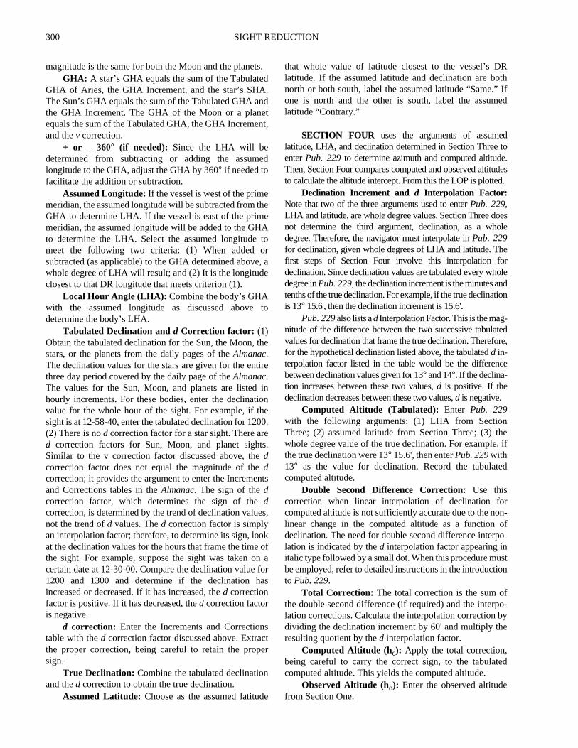
2006. Reducing Star Sights to a Fix
On May 16, 1995, at the times indicated, the navigatortakes and records the following sights:
Height of eye is 48 feet and index correction (IC) is+2.1'. The DR latitude for both sights is 39° N. The DRlongitude for the Spica sight is 157° 10'W. The DRlongitude for the Kochab sight is 157° 08.0'W. Determinethe intercept and azimuth for both sights. See Figure 2006.
First, convert the sextant altitudes to observedaltitudes. Reduce the Spica sight first:
Determine the sum of the index correction and the dipcorrection. Go to the inside front cover of theNauticalAlmanac to the table entitled “DIP.” This table lists dipcorrections as a function of height of eye measured in eitherfeet or meters. In the above problem, the observer’s height ofeye is 48 feet. The heights of eye are tabulated in intervals,
with the correction corresponding to each interval listebetween the interval’s endpoints. In this case, 48 feet lbetween the tabulated 46.9 to 48.4 feet interval; tcorresponding correction for this interval is -6.7'. Add the Iand the dip correction, being careful to carry the correct sigThe sum of the corrections here is -4.6'. Apply this correctioto the sextant altitude to obtain the apparent altitude (ha).
Next, apply the altitude correction. Find the altitudcorrection table on the inside front cover of theNauticalAlmanacnext to the dip table. The altitude correction varieas a function of both the type of body sighted (Sun, star,planet) and the body’s apparent altitude. For the probleabove, enter the star altitude correction table. Again, tcorrection is given within an altitude interval; ha in this casewas 32° 30.2'. This value lies between the tabulateendpoints 32° 00.0' and 33° 45.0'. The correctioncorresponding to this interval is -1.5'. Applying thiscorrection to ha yields an observed altitude of 32° 28.7'.
Having calculated the observed altitude, determine ttime and date of the sight in Greenwich Mean Time:
Record the observation time and then apply any waterror to determine zone time. Then, use the DR longitudethe time of the sight to determine time zone description.this case, the DR longitude indicates a zone description+10 hours. Add the zone description to the zone timeobtain GMT. It is important to carry the correct date wheapplying this correction. In this case, the +10 correctiomade it 06-11-26 GMT on May17, when the date in thelocal time zone was May16.
After calculating both the observed altitude and the GM
LHA 180° then Zn Z=,>LHA 180° then Zn 360° Z–=,<
LHA 180° then Zn 180° Z–=,>LHA 180° then Zn 180°+Z=,<
Star Sextant Altitude Zone Time
Kochab 47° 19.1' 20-07-43Spica 32° 34.8' 20-11-26
Body SpicaIndex Correction +2.1'Dip (height 48 ft) -6.7'Sum -4.6'Sextant Altitude (hs) 32° 34.8'Apparent Altitude (ha) 32° 30.2'Altitude Correction -1.5'Additional Correction 0Horizontal Parallax 0Correction to ha -1.5'Observed Altitude (ho) 32° 28.7'
Date 16 May 1995DR Latitude 39° NDR Longitude 157° 10' WObservation Time 20-11-26Watch Error 0Zone Time 20-11-26Zone Description +10GMT 06-11-26GMT Date 17 May 1995
302 SIGHT REDUCTION
is
oned
1
isec-ofre-
atfor
e
eesislne
edleralisge
g,e
is
en
time, enter the daily pages of theNautical Almanactocalculate the star’s Greenwich Hour Angle (GHA) anddeclination.
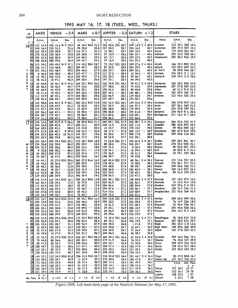
First, record the GHA of Aries from the May 17, 1995daily page: 324° 28.4'.
Next, determine the incremental addition for theminutes and seconds after 0600 from the Increments andCorrections table in the back of theNautical Almanac. Theincrement for 11 minutes and 26 seconds is 2° 52'.
Then, calculate the GHA of the star. Remember:
GHA (star) = GHA + SHA (star)
TheNautical Almanaclists the SHA of selected stars oneach dailypage. TheSHA of Spicaon May17, 1995:158° 45.3'.
Pub. 229’s entering arguments are whole degrees ofLHA and assumed latitude. Remember that LHA = GHA -west longitude or GHA + east longitude. Since in thisexample the vessel is in west longitude, subtract itsassumed longitude from the GHA of the body to obtain theLHA. Assume a longitude meeting the criteria listed inArticle 2005.
From those criteria, the assumed longitude must end in05.7 minutes so that, when subtracted from the calculatedGHA, a whole degree of LHA will result. Since the DRlongitude was 157° 10.0', then the assumed longitudeending in 05.7' closest to the DR longitude is 157° 05.7'.Subtracting this assumed longitude from the calculatedGHA of the star yields an LHA of 329°.
The next value of concern is the star’s true declination.This value is found on the May 17th daily page next to thestar’s SHA. Spica’s declination is S 11° 08.4'. There is no dcorrection for a star sight, so the star’s true declinationequals its tabulated declination. The assumed latitude isdetermined from the whole degree of latitude closest to theDR latitude at the time of the sight. In this case, the assumedlatitude is N 39°. It is marked “contrary” because the DRlatitude is north while the star’s declination is south.
The following information is known: (1) the assumed
position’s LHA (329°) and assumed latitude (39°Ncontrary name); and (2) the body’s declination (S11° 08.4').
Find the page in theSight Reduction Tablecorresponding to an LHA of 329° and an assumed latitudeof N 39°, with latitude contrary to declination. Enter thistable with the body’s whole degree of declination. In thcase, the body’s whole degree of declination is 11°. Thisdeclination corresponds to a tabulated altitude of 32° 15.9'.This value is for a declination of 11°; the true declination is11° 08.4'. Therefore, interpolate to determine the correctito add to the tabulated altitude to obtain the computaltitude.
The difference between the tabulated altitudes for 1°and 12° is given inPub. 229as the value d; in this case, d =-53.0. Express as a ratio the declination increment (in thcase, 8.4') and the total interval between the tabulated dlination values (in this case, 60') to obtain the percentagethe distance between the tabulated declination values repsented by the declination increment. Next, multiply thpercentage by the increment between the two valuescomputed altitude. In this case:
Subtract 7.4' from the tabulated altitude to obtain thfinal computed altitude: Hc = 32° 08.5'.
It will be valuable here to review exactly what hoand hc represent. Recall the methodology of thaltitude-intercept method. The navigator first measurand corrects an altitude for a celestial body. Thcorrected altitude, ho, corresponds to a circle of equaaltitude passing through the navigator’s actual positiowhose center is the geographic position (GP) of thbody. The navigator then determines an assumposition (AP) near, but not coincident with, his actuaposition; he then calculates an altitude for an observat that assumed position (AP).The circle of equaltitude passing through this assumed positionconcentric with the circle of equal altitude passinthrough the navigator’s actual position. The differencbetween the body’s altitude at the assumed position (hc)and the body’s observed altitude (ho) is equal to thedifferences in radii length of the two correspondincircles of equal altitude. In the above problemtherefore, the navigator knows that the equal altitudcircle passing through his actual position is:away from the equal altitude circle passing through hassumed position. Since ho is greater than hc, thenavigator knows that the radius of the equal altitudcircle passing through his actual position is less tha
Tab GHA 324° 28.4'GHA Increment 2° 52.0'SHA 158° 45.3'GHA 486° 05.7'+/- 360° not required
Assumed Longitude 157° 05.7'LHA 329°Tabulated Dec/d S 11° 08.4'/n.a.d Correction —True Declination S 11° 08.4'Assumed Latitude N 39° contrary
Dec Inc / + or - d 8.4' / -53.0hc (tabulated) 32° 15.9'Correction (+ or -) -7.4'hc (computed) 32° 08.5'
8.460------- 53.0–( )× 7.4–=
SIGHT REDUCTION 303
nm-deer-
i-she2
fer-isn’sies
endern-
onehe
talde
.
the radius of the equal altitude circle passing throughthe assumed position. The only remaining question is: inwhat direction from the assumed position is the body’sactual GP.Pub. 229also provides this final piece ofinformation. This is the value for Z tabulated with the hcand d values discussed above. In this case, enterPub. 229as before, with LHA, assumed latitude, and declination.Visual interpolation is sufficient. Extract the value Z =143.3°. The relation between Z and Zn, the true azimuth,is as follows:
In northern latitudes:
In southern latitudes:
In this case, LHA > 180° and the vessel is in northern lati-tude. Therefore, Zn = Z = 143.3°T. The navigator now hasenough information to plot a line of position.
The values for the reduction of the Kochab sight follow:
2007. Reducing a Sun Sight
The example below points out the similarities betweereducing a Sun sight and reducing a star sight. It also deonstrates the additional corrections required for low altitu(<10°) sights and sights taken during non-standard tempature and pressure conditions.
On June 16, 1994, at 05-15-23 local time, at DR postion L 30°N λ 45°W, a navigator takes a sight of the Sun’upper limb. The navigator has a height of eye of 18 feet, ttemperature is 88° F, and the atmospheric pressure is 98mb. The sextant altitude is 3° 20.2'. There is no index error.Determine the observed altitude. See Figure 2007.
Apply the index and dip corrections to hs to obtain ha.Because hais less than 10°, use the special altitude correctiontable for sights between 0° and 10° located on the right insidefront page of theNautical Almanac.
Enter the table with the apparent altitude, the limb othe Sun used for the sight, and the period of the year. Intpolation for the apparent altitude is not required. In thcase, the table yields a correction of -29.4'. The correctioalgebraic sign is found at the head of each group of entrand at every change of sign.
The additional correction is required because of thnon-standard temperature and atmospheric pressure uwhich the sight was taken. The correction for these nostandard conditions is found in theAdditional Correctionstable located on page A4 in the front of theNauticalAlmanac.
First, enter theAdditional Correctionstable with thetemperature and pressure to determine the correct zletter: in this case, zone L. Then, locate the correction in tL column corresponding to the apparent altitude of 3° 16.1'.Interpolate between the table arguments of 3° 00.0' and 3°30.0' to determine the additional correction: +1.4'. The tocorrection to the apparent altitude is the sum of the altituand additional corrections: -28.0'. This results in an ho of2° 48.1'.
Next, determine the Sun’s GHA and declination
Body KochabIndex Correction +2.1'Dip Correction -6.7'Sum -4.6'hs 47° 19.1'ha 47° 14.5'Altitude Correction -.9'Additional Correction not applicableHorizontal Parallax not applicableCorrection to ha -9'ho 47° 13.6'Date 16 May 1995DR latitude 39°NDR longitude 157° 08.0' WObservation Time 20-07-43Watch Error 0Zone Time 20-07-43Zone Description +10GMT 06-07-43GMT Date 17 May 1995Tab GHA 324° 28.4'GHA Increment 1° 56.1'SHA 137° 18.5'
ho 32°28.7′=
h– c32°08.5′
20.2 NM--------------------------------=
LHA 180° then Zn Z=,>LHA 180° then Zn 360° Z–=,<
LHA 180° then Zn 180° Z–=,>LHA 180° then Zn 180° Z+=,<
GHA 463° 43.0'+/- 360° not applicableAssumed Longitude 156° 43.0'LHA 307°Tab Dec /d N74° 10.6' / n.a.d Correction not applicableTrue Declination N74° 10.6'Assumed Latitude 39°N (same)Dec Inc / + or - d 10.6' / -24.8hc 47° 12.6'Total Correction -4.2'hc (computed) 47° 08.4'ho 47° 13.6'a (intercept) 5.2 towardsZ 018.9°Zn 018.9°
304 SIGHT REDUCTION
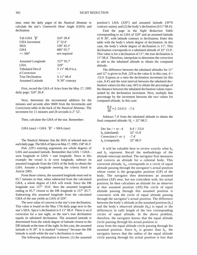
Figure 2006. Left hand daily page of the Nautical Almanac for May 17, 1995.
SIGHT REDUCTION 305
d
e
gs
a
ns
unon
eeisard
nhe
rtoP
yenter
yU”,
Again, this process is similar to the star sights reducedabove. Notice, however, that SHA, a quantity unique to starsight reduction, is not used in Sun sight reduction.
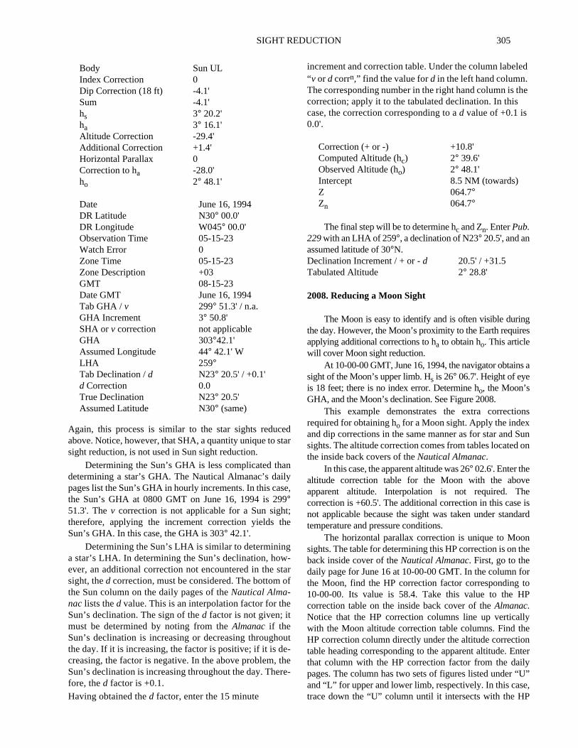
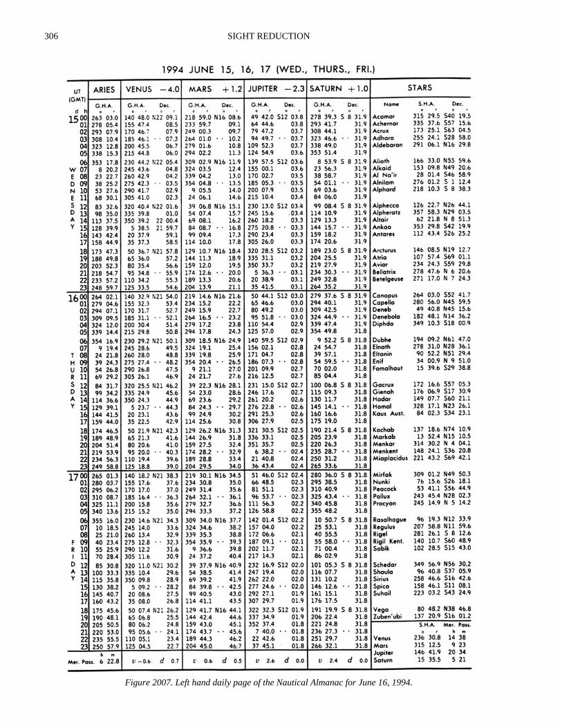
Determining the Sun’s GHA is less complicated thandetermining a star’s GHA. The Nautical Almanac’s dailypages list the Sun’s GHA in hourly increments. In this case,the Sun’s GHA at 0800 GMT on June 16, 1994 is 299°51.3'. Thev correction is not applicable for a Sun sight;therefore, applying the increment correction yields theSun’s GHA. In this case, the GHA is 303° 42.1'.
Determining the Sun’s LHA is similar to determininga star’s LHA. In determining the Sun’s declination, how-ever, an additional correction not encountered in the starsight, thed correction, must be considered. The bottom ofthe Sun column on the daily pages of theNautical Alma-nac lists thed value. This is an interpolation factor for theSun’s declination. The sign of thed factor is not given; itmust be determined by noting from theAlmanac if theSun’s declination is increasing or decreasing throughoutthe day. If it is increasing, the factor is positive; if it is de-creasing, the factor is negative. In the above problem, theSun’s declination is increasing throughout the day. There-fore, thed factor is +0.1.
Having obtained thed factor, enter the 15 minute
increment and correction table. Under the column labele“v or d corrn,” find the value ford in the left hand column.The corresponding number in the right hand column is thcorrection; apply it to the tabulated declination. In thiscase, the correction corresponding to ad value of +0.1 is0.0'.
The final step will be to determine hc and Zn. EnterPub.229with an LHA of 259°, a declination of N23° 20.5', and anassumed latitude of 30°N.
2008. Reducing a Moon Sight
The Moon is easy to identify and is often visible durinthe day. However, the Moon’s proximity to the Earth requireapplying additional corrections to ha to obtain ho. This articlewill cover Moon sight reduction.
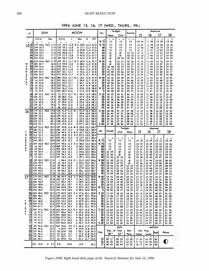
At 10-00-00 GMT, June 16, 1994, the navigator obtainssight of the Moon’s upper limb. Hs is 26° 06.7'. Height of eyeis 18 feet; there is no index error. Determine ho, the Moon’sGHA, and the Moon’s declination. See Figure 2008.
This example demonstrates the extra correctiorequired for obtaining ho for a Moon sight. Apply the indexand dip corrections in the same manner as for star and Ssights. The altitude correction comes from tables locatedthe inside back covers of theNautical Almanac.
In this case, the apparent altitude was 26° 02.6'. Enter thealtitude correction table for the Moon with the abovapparent altitude. Interpolation is not required. Thcorrection is +60.5'. The additional correction in this casenot applicable because the sight was taken under standtemperature and pressure conditions.
The horizontal parallax correction is unique to Moosights. The table for determining this HP correction is on tback inside cover of theNautical Almanac. First, go to thedaily page for June 16 at 10-00-00 GMT. In the column fothe Moon, find the HP correction factor corresponding10-00-00. Its value is 58.4. Take this value to the Hcorrection table on the inside back cover of theAlmanac.Notice that the HP correction columns line up verticallwith the Moon altitude correction table columns. Find thHP correction column directly under the altitude correctiotable heading corresponding to the apparent altitude. Enthat column with the HP correction factor from the dailpages. The column has two sets of figures listed under “and “L” for upper and lower limb, respectively. In this casetrace down the “U” column until it intersects with the HP
Body Sun ULIndex Correction 0Dip Correction (18 ft) -4.1'Sum -4.1'hs 3° 20.2'ha 3° 16.1'Altitude Correction -29.4'Additional Correction +1.4'Horizontal Parallax 0Correction to ha -28.0'ho 2° 48.1'
Date June 16, 1994DR Latitude N30° 00.0'DR Longitude W045° 00.0'Observation Time 05-15-23Watch Error 0Zone Time 05-15-23Zone Description +03GMT 08-15-23Date GMT June 16, 1994Tab GHA /v 299° 51.3' / n.a.GHA Increment 3° 50.8'SHA orv correction not applicableGHA 303°42.1'Assumed Longitude 44° 42.1' WLHA 259°Tab Declination /d N23° 20.5' / +0.1'd Correction 0.0True Declination N23° 20.5'Assumed Latitude N30° (same)
Correction (+ or -) +10.8'Computed Altitude (hc) 2° 39.6'Observed Altitude (ho) 2° 48.1'Intercept 8.5 NM (towards)Z 064.7°Zn 064.7°
Declination Increment / + or -d 20.5' / +31.5Tabulated Altitude 2° 28.8'
306 SIGHT REDUCTION
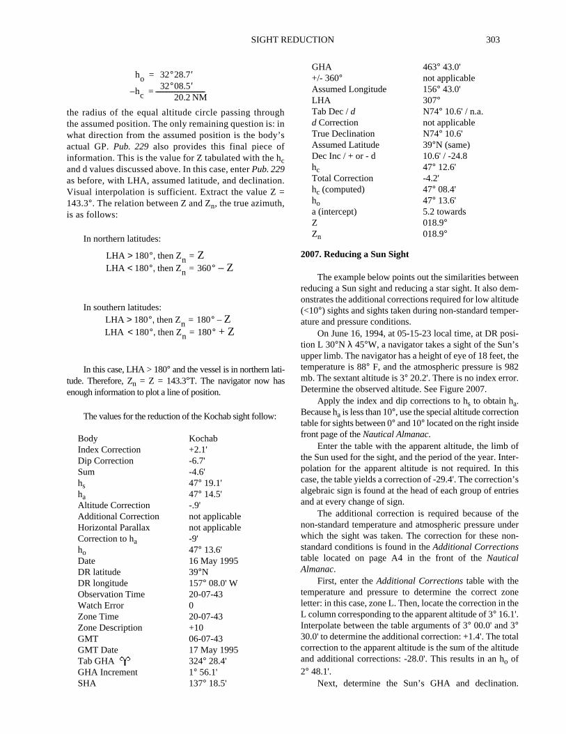
Figure 2007. Left hand daily page of the Nautical Almanac for June 16, 1994.
SIGHT REDUCTION 307
t
ng
ne’s
y
ld.
S
,the
in
s,tont
rt
te
ennd
ex-ntrs
lepres-a
rs
ofheforr-
correction factor of 58.4. Interpolating between 58.2 and58.5 yields a value of +4.0' for the horizontal parallaxcorrection.
The final correction is a constant -30.0' correction to haapplied only to sights of the Moon’s upper limb. This correctionis always negative; apply it only to sights of the Moon’s upperlimb, not its lower limb. The total correction to ha is the sum ofall the corrections; in this case, this total correction is +34.5minutes.
To obtain the Moon’s GHA, enter the daily pages in theMoon column and extract the applicable data just as for a star orSun sight. Determining the Moon’s GHA requires an additionalcorrection, thev correction.
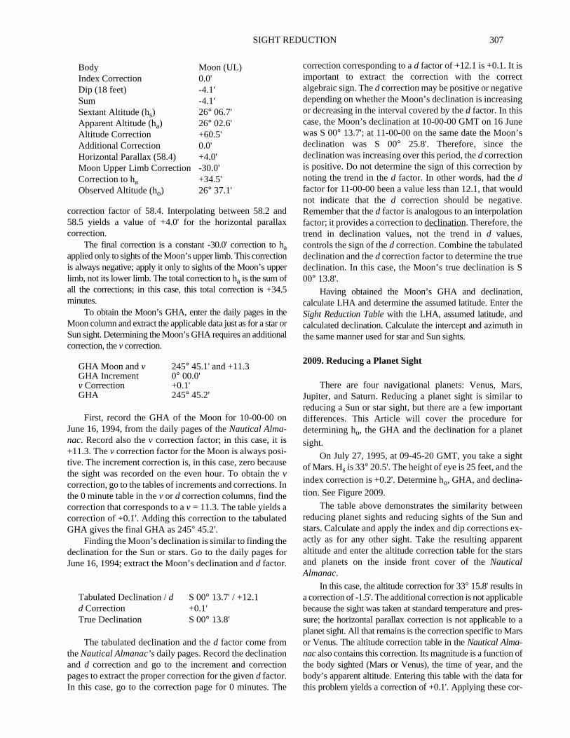
First, record the GHA of the Moon for 10-00-00 onJune 16, 1994, from the daily pages of theNautical Alma-nac. Record also thev correction factor; in this case, it is+11.3. Thev correction factor for the Moon is always posi-tive. The increment correction is, in this case, zero becausethe sight was recorded on the even hour. To obtain thevcorrection, go to the tables of increments and corrections. Inthe 0 minute table in thev or d correction columns, find thecorrection that corresponds to av = 11.3. The table yields acorrection of +0.1'. Adding this correction to the tabulatedGHA gives the final GHA as 245° 45.2'.
Finding the Moon’s declination is similar to finding thedeclination for the Sun or stars. Go to the daily pages forJune 16, 1994; extract the Moon’s declination andd factor.
The tabulated declination and thed factor come fromtheNautical Almanac’sdaily pages. Record the declinationand d correction and go to the increment and correctionpages to extract the proper correction for the givend factor.In this case, go to the correction page for 0 minutes. The
correction corresponding to ad factor of +12.1 is +0.1. It isimportant to extract the correction with the correcalgebraic sign. Thed correction may be positive or negativedepending on whether the Moon’s declination is increasior decreasing in the interval covered by thed factor. In thiscase, the Moon’s declination at 10-00-00 GMT on 16 Juwas S 00° 13.7'; at 11-00-00 on the same date the Moondeclination was S 00° 25.8'. Therefore, since thedeclination was increasing over this period, thed correctionis positive. Do not determine the sign of this correction bnoting the trend in thed factor. In other words, had thedfactor for 11-00-00 been a value less than 12.1, that wounot indicate that thed correction should be negativeRemember that thed factor is analogous to an interpolationfactor; it provides a correction todeclination. Therefore, thetrend in declination values, not the trend ind values,controls the sign of thed correction. Combine the tabulateddeclination and thed correction factor to determine the truedeclination. In this case, the Moon’s true declination is00° 13.8'.
Having obtained the Moon’s GHA and declinationcalculate LHA and determine the assumed latitude. EnterSight Reduction Tablewith the LHA, assumed latitude, andcalculated declination. Calculate the intercept and azimuththe same manner used for star and Sun sights.
2009. Reducing a Planet Sight
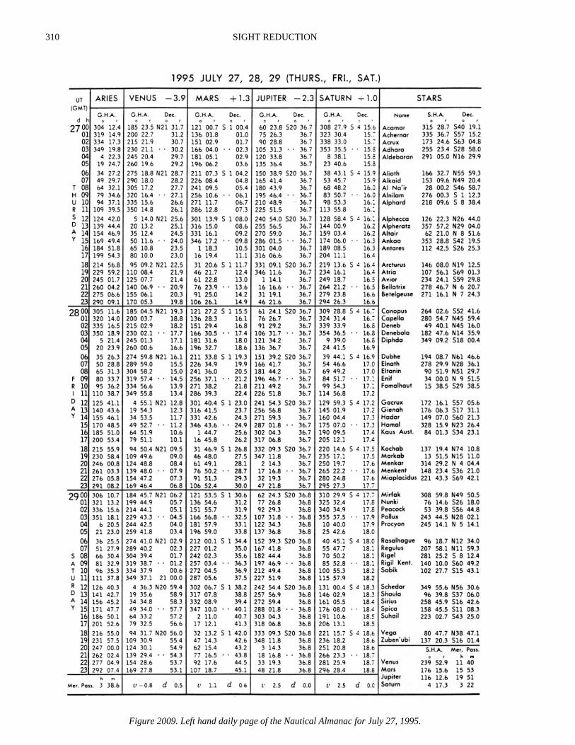
There are four navigational planets: Venus, MarJupiter, and Saturn. Reducing a planet sight is similarreducing a Sun or star sight, but there are a few importadifferences. This Article will cover the procedure fodetermining ho, the GHA and the declination for a planesight.
On July 27, 1995, at 09-45-20 GMT, you take a sighof Mars. Hs is 33° 20.5'. The height of eye is 25 feet, and thindex correction is +0.2'. Determine ho, GHA, and declina-tion. See Figure 2009.
The table above demonstrates the similarity betwereducing planet sights and reducing sights of the Sun astars. Calculate and apply the index and dip correctionsactly as for any other sight. Take the resulting apparealtitude and enter the altitude correction table for the staand planets on the inside front cover of theNauticalAlmanac.
In this case, the altitude correction for 33° 15.8' results ina correction of -1.5'. The additional correction is not applicabbecause the sight was taken at standard temperature andsure; the horizontal parallax correction is not applicable toplanet sight. All that remains is the correction specific to Maor Venus. The altitude correction table in theNautical Alma-nacalso contains this correction. Its magnitude is a functionthe body sighted (Mars or Venus), the time of year, and tbody’s apparent altitude. Entering this table with the datathis problem yields a correction of +0.1'. Applying these co
Body Moon (UL)Index Correction 0.0'Dip (18 feet) -4.1'Sum -4.1'Sextant Altitude (hs) 26° 06.7'Apparent Altitude (ha) 26° 02.6'Altitude Correction +60.5'Additional Correction 0.0'Horizontal Parallax (58.4) +4.0'Moon Upper Limb Correction -30.0'Correction to ha +34.5'Observed Altitude (ho) 26° 37.1'
GHA Moon andv 245° 45.1' and +11.3GHA Increment 0° 00.0'v Correction +0.1'GHA 245° 45.2'
Tabulated Declination / d S 00° 13.7' / +12.1d Correction +0.1'True Declination S 00° 13.8'
308 SIGHT REDUCTION
Figure 2008. Right hand daily page of the Nautical Almanac for June 16, 1994.

SIGHT REDUCTION 309
n
the
ly
hee
ong
terd
e
ther’sl’sthe
eral
for
sthee isheest
32The
eN,
of
ofe.nhis
rections to ha results in an ho of 33° 14.4'.
The only difference between determining the Sun’s GHAand a planet’s GHA lies in applying thevcorrection. Calculatethis correction from thev or d correction section of the Incre-ments and Correction table in theNautical Almanac.Find thev factor at the bottom of the planets’ GHA columnson the daily pages of theNautical Almanac. For Mars on
July 27, 1995, thev factor is 1.1. If no algebraic signprecedes thev factor, add the resulting correction to thetabulated GHA. Subtract the resulting correction only whea negative sign precedes thev factor. Entering thev or dcorrection table corresponding to 45 minutes yields acorrection of 0.8'. Remember, because no sign precededv factor on the daily pages, add this correction to thetabulated GHA. The final GHA is 267°31.4'.
Read the tabulated declination directly from the daipages of theNautical Almanac. The d correction factor islisted at the bottom of the planet column; in this case, tfactor is 0.6. Note the trend in the declination values for thplanet; if they are increasing during the day, the correctifactor is positive. If the planet’s declination is decreasinduring the day, the correction factor is negative. Next, enthev or d correction table corresponding to 45 minutes anextract the correction for ad factor of 0.6. The correction inthis case is +0.5'.
From this point, reducing a planet sight is exactly thsame as reducing a Sun sight.
MERIDIAN PASSAGE
This section covers determining both latitude andlongitude at the meridian passage of the Sun, or LocalApparent Noon (LAN). Determining a vessel’s latitude atLAN requires calculating the Sun’s zenith distance anddeclination and combining them according to the rulesdiscussed below.
Latitude at LAN is a special case of the navigationaltriangle where the Sun is on the observer’s meridian and thetriangle becomes a straight north/south line. No “solution” isnecessary, except to combine the Sun’s zenith distance andits declination according to the rules discussed below.
Longitude at LAN is a function of the time elapsed since theSun passed the Greenwich meridian. The navigator mustdetermine the time of LAN and calculate the GHA of the Sun atthat time. The following examples demonstrates these processes.
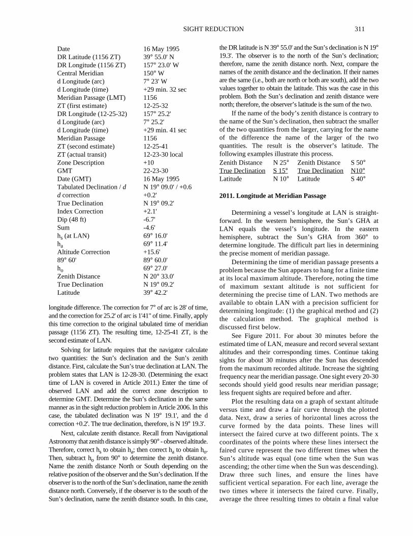
2010. Latitude at Meridian Passage
At 1056 ZT, May 16, 1995, a vessel’s DR position is L40° 04.3'N andλ 157° 18.5' W. The ship is on course 200°Tat a speed of ten knots. (1) Calculate the first and second es-timates of Local Apparent Noon. (2) The navigator actuallyobserves LAN at 12-23-30 zone time. The sextant altitudeat LAN is 69° 16.0'. The index correction is +2.1' and theheight of eye is 45 feet. Determine the vessel’s latitude.
First, determine the time of meridian passage from the dailypages of theNautical Almanac. In this case, the meridian
passage for May 16, 1995, is 1156. That is, the Sun crossescentral meridian of the time zone at 1156 ZT and the observelocal meridian at 1156 local time. Next, determine the vesseDR longitude for the time of meridian passage. In this case,vessel’s 1156 DR longitude is 157° 23.0' W. Determine the timezone in which this DR longitude falls and record the longitudof that time zone’s central meridian. In this case, the centmeridian is 150° W. Enter the Conversion of Arc to Time tablein theNautical Almanacwith the difference between the DRlongitude and the central meridian longitude. The conversion7° of arc is 28m of time, and the conversion for 23' of arc is1m32s of time. Sum these two times. If the DR position is weof the central meridian (as it is in this case), add this time to ttime of tabulated meridian passage. If the longitude differencto the east of the central meridian, subtract this time from ttabulated meridian passage. In this case, the DR position is wof the central meridian. Therefore, add 29 minutes andseconds to 1156, the tabulated time of meridian passage.estimated time of LAN is 12-25-32 ZT.
This first estimate for LAN does not take into account thvessel’s movement. To calculate the second estimate of LAfirst determine the DR longitude for the time of first estimateLAN (12-25-32 ZT). In this case, that longitude would be 157°25.2' W. Then, calculate the difference between the longitudethe 12-25-32 DR position and the central meridian longitudThis would be 7° 25.2'. Again, enter the arc to time conversiotable and calculate the time difference corresponding to t
Body MarsIndex Correction +0.2'Dip Correction (25 feet) -4.9'Sum -4.7'hs 33° 20.5'ha 33° 15.8'Altitude Correction -1.5'Additional Correction Not applicableHorizontal Parallax Not applicableAdditional Correction for Mars +0.1'Correction to ha -1.4'ho 33° 14.4'
Tabulated GHA /v 256°10.6' / 1.1GHA Increment 11° 20.0'v correction +0.8'GHA 267°31.4'
Tabulated Declination /d S 01° 06.1' / 0.6d Correction +0.5'True Declination S 01° 06.6'
310 SIGHT REDUCTION
Figure 2009. Left hand daily page of the Nautical Almanac for July 27, 1995.
SIGHT REDUCTION 311
n;theestwothisere.tollereoe
-atrn
g
s amee
e
2)is
heantngdedng-30ge;
ed
hellx
thee
asg).vehe,
ue
longitude difference. The correction for 7° of arc is 28' of time,and the correction for 25.2' of arc is 1'41" of time. Finally, applythis time correction to the original tabulated time of meridianpassage (1156 ZT). The resulting time, 12-25-41 ZT, is thesecond estimate of LAN.
Solving for latitude requires that the navigator calculatetwo quantities: the Sun’s declination and the Sun’s zenithdistance. First, calculate the Sun’s true declination at LAN. Theproblem states that LAN is 12-28-30. (Determining the exacttime of LAN is covered in Article 2011.) Enter the time ofobserved LAN and add the correct zone description todetermine GMT. Determine the Sun’s declination in the samemanner as in the sight reduction problem in Article 2006. In thiscase, the tabulated declination was N 19° 19.1', and the dcorrection +0.2'. The true declination, therefore, is N 19° 19.3'.
Next, calculate zenith distance. Recall from NavigationalAstronomy that zenith distance issimply 90° - observed altitude.Therefore, correct hs to obtain ha; then correct ha to obtain ho.Then, subtract ho from 90° to determine the zenith distance.Name the zenith distance North or South depending on therelative position of the observer and the Sun’s declination. If theobserver is to the north of the Sun’s declination, name the zenithdistance north. Conversely, if the observer is to the south of theSun’s declination, name the zenith distance south. In this case,
the DR latitude is N 39° 55.0' and the Sun’s declination is N 19°19.3'. The observer is to the north of the Sun’s declinatiotherefore, name the zenith distance north. Next, comparenames of the zenith distance and the declination. If their namare the same (i.e., both are north or both are south), add thevalues together to obtain the latitude. This was the case inproblem. Both the Sun’s declination and zenith distance wnorth; therefore, the observer’s latitude is the sum of the two
If the name of the body’s zenith distance is contrarythe name of the Sun’s declination, then subtract the smaof the two quantities from the larger, carrying for the namof the difference the name of the larger of the twquantities. The result is the observer’s latitude. Thfollowing examples illustrate this process.
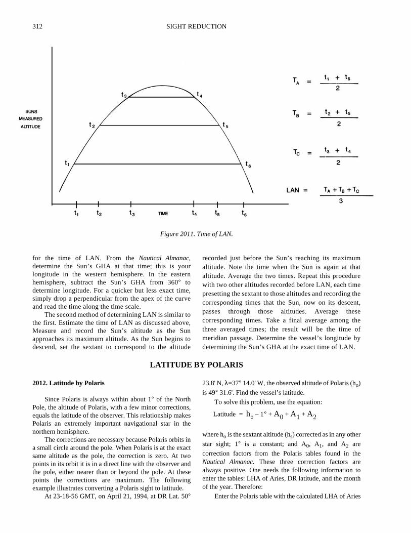
2011. Longitude at Meridian Passage
Determining a vessel’s longitude at LAN is straightforward. In the western hemisphere, the Sun’s GHALAN equals the vessel’s longitude. In the eastehemisphere, subtract the Sun’s GHA from 360° todetermine longitude. The difficult part lies in determininthe precise moment of meridian passage.
Determining the time of meridian passage presentproblem because the Sun appears to hang for a finite tiat its local maximum altitude. Therefore, noting the timof maximum sextant altitude is not sufficient fordetermining the precise time of LAN. Two methods aravailable to obtain LAN with a precision sufficient fordetermining longitude: (1) the graphical method and (the calculation method. The graphical methoddiscussed first below.
See Figure 2011. For about 30 minutes before testimated time of LAN, measure and record several sextaltitudes and their corresponding times. Continue takisights for about 30 minutes after the Sun has descenfrom the maximum recorded altitude. Increase the sightifrequency near the meridian passage. One sight every 20seconds should yield good results near meridian passaless frequent sights are required before and after.
Plot the resulting data on a graph of sextant altitudversus time and draw a fair curve through the plottedata. Next, draw a series of horizontal lines across tcurve formed by the data points. These lines wiintersect the faired curve at two different points. Thecoordinates of the points where these lines intersectfaired curve represent the two different times when thSun’s altitude was equal (one time when the Sun wascending; the other time when the Sun was descendinDraw three such lines, and ensure the lines hasufficient vertical separation. For each line, average ttwo times where it intersects the faired curve. Finallyaverage the three resulting times to obtain a final val
Date 16 May 1995DR Latitude (1156 ZT) 39° 55.0' NDR Longitude (1156 ZT) 157° 23.0' WCentral Meridian 150° Wd Longitude (arc) 7° 23' Wd Longitude (time) +29 min. 32 secMeridian Passage (LMT) 1156ZT (first estimate) 12-25-32DR Longitude (12-25-32) 157° 25.2'd Longitude (arc) 7° 25.2'd Longitude (time) +29 min. 41 secMeridian Passage 1156ZT (second estimate) 12-25-41ZT (actual transit) 12-23-30 localZone Description +10GMT 22-23-30Date (GMT) 16 May 1995Tabulated Declination /d N 19° 09.0' / +0.6d correction +0.2'True Declination N 19° 09.2'Index Correction +2.1'Dip (48 ft) -6.7'Sum -4.6'hs (at LAN) 69° 16.0'ha 69° 11.4'Altitude Correction +15.6'89° 60' 89° 60.0'ho 69° 27.0'Zenith Distance N 20° 33.0'True Declination N 19° 09.2'Latitude 39° 42.2'
Zenith Distance N 25° Zenith Distance S 50°True Declination S 15° True Declination N10°Latitude N 10° Latitude S 40°
312 SIGHT REDUCTION
matreethent,seheofby
eeoth
s
for the time of LAN. From the Nautical Almanac,determine the Sun’s GHA at that time; this is yourlongitude in the western hemisphere. In the easternhemisphere, subtract the Sun’s GHA from 360° todetermine longitude. For a quicker but less exact time,simply drop a perpendicular from the apex of the curveand read the time along the time scale.
The second method of determining LAN is similar tothe first. Estimate the time of LAN as discussed above,Measure and record the Sun’s altitude as the Sunapproaches its maximum altitude. As the Sun begins todescend, set the sextant to correspond to the altitude
recorded just before the Sun’s reaching its maximualtitude. Note the time when the Sun is again at thaltitude. Average the two times. Repeat this proceduwith two other altitudes recorded before LAN, each timpresetting the sextant to those altitudes and recordingcorresponding times that the Sun, now on its descepasses through those altitudes. Average thecorresponding times. Take a final average among tthree averaged times; the result will be the timemeridian passage. Determine the vessel’s longitudedetermining the Sun’s GHA at the exact time of LAN.
LATITUDE BY POLARIS
2012. Latitude by Polaris
Since Polaris is always within about 1° of the NorthPole, the altitude of Polaris, with a few minor corrections,equals the latitude of the observer. This relationship makesPolaris an extremely important navigational star in thenorthern hemisphere.
The corrections are necessary because Polaris orbits ina small circle around the pole. When Polaris is at the exactsame altitude as the pole, the correction is zero. At twopoints in its orbit it is in a direct line with the observer andthe pole, either nearer than or beyond the pole. At thesepoints the corrections are maximum. The followingexample illustrates converting a Polaris sight to latitude.
At 23-18-56 GMT, on April 21, 1994, at DR Lat. 50°
23.8' N,λ=37° 14.0' W, the observed altitude of Polaris (ho)
is 49° 31.6'. Find the vessel’s latitude.
To solve this problem, use the equation:
where ho is the sextant altitude (hs) corrected as in any other
star sight; 1° is a constant; and A0, A1, and A2 are
correction factors from the Polaris tables found in thNautical Almanac. These three correction factors aralways positive. One needs the following information tenter the tables: LHA of Aries, DR latitude, and the monof the year. Therefore:
Enter the Polaris table with the calculated LHA of Arie
Figure 2011. Time of LAN.
Latitude ho 1° A0 A1 A2+ + +–=
SIGHT REDUCTION 313
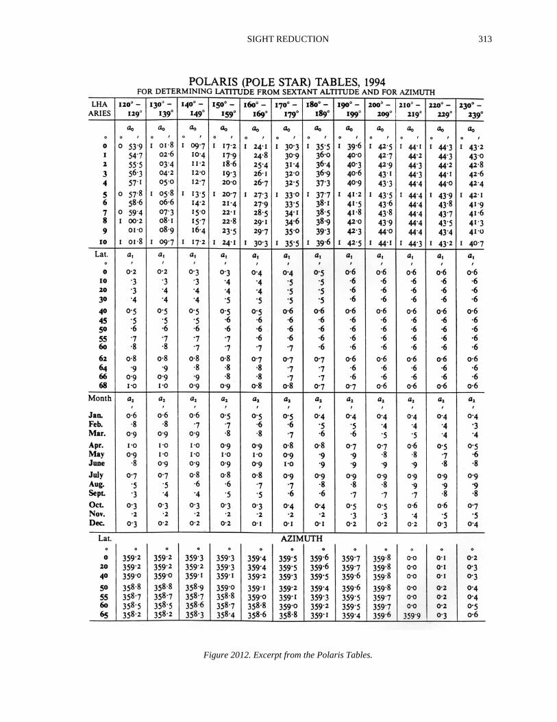
Figure 2012. Excerpt from the Polaris Tables.
314 SIGHT REDUCTION
ly. In
in
re
e.
ss
gr-
ht.n-
ckva-n
-
ts-
ex-us
(162° 03.5'). See Figure 2012. The first correction, A0, is a
function solely of the LHA of Aries. Enter the table columnindicating the proper range of LHA of Aries; in this case,enter the 160°-169° column. The numbers on the left handside of the A0 correction table represent the whole degrees of
LHA ; interpolate to determine the proper A0 correction.
In this case, LHA was 162° 03.5'. The A0 correction for
LHA = 162° is 1° 25.4' and the A0 correction for LHA = 163°is 1° 26.1'. The A0 correction for 162° 03.5' is 1° 25.4'.
To calculate the A1 correction, enter the A1 correctiontable with the DR latitude, being careful to stay in the 160°-169° LHA column. There is no need to interpolate here; simpchoose the latitude that is closest to the vessel’s DR latitudethis case, L is 50°N. The A1 correction corresponding to anLHA range of 160°-169° and a latitude of 50°N is + 0.6'.
Finally, to calculate the A2 correction factor, stay in the160°-169° LHA column and enter the A2 correctiontable. Follow the column down to the month of the year;this case, it is April. The correction for April is + 0.9'.
Sum the corrections, remembering that all three aalways positive. Subtract 1° from the sum to determine thetotal correction; then apply the resulting value to thobserved altitude of Polaris. This is the vessel’s latitude
THE DAY’S WORK IN CELESTIAL NAVIGATION
2013. Celestial Navigation Daily Routine
The navigator need not follow the entire celestial rou-tine if celestial navigation is not the primary navigationmethod. It is appropriate to use only the steps of the celes-tial day’s work that are necessary to provide a meaningfulcheck on the primary fix source and maintain competencyin celestial techniques.
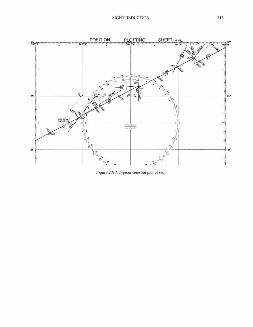
The list of procedures below provides a complete dailycelestial routine to follow. This sequence works equallywell for all sight reduction methods, whether tabular, math-ematical, computer program, or celestial navigationcalculator. See Figure 2013 for an example of a typicalday’s celestial plot.
1. Before dawn, compute the time of morning twilightand plot the dead reckoning position for that time.2. At morning twilight, take and reduce celestial obser-vations for a fix. At sunrise take an amplitude of theSun for a compass check.3. Mid-morning, wind the chronometer and determinechronometer error with a radio time tick.4. Mid-morning, reduce a Sun sight for a morning Sun
line.5. Calculate an azimuth of the Sun for a compacheck, if no amplitude was taken at sunrise.6. At LAN, obtain a Sun line and advance the morninSun line for the noon fix. Compute a longitude detemined at LAN for an additional LOP.7. Mid afternoon, again take and reduce a Sun sigThis is primarily for use with an advanced noon Suline, or with a Moon or Venus line if the skies are overcast during evening twilight.8. Calculate an azimuth of the Sun for a compass cheat about the same time as the afternoon Sun obsertion. The navigator may replace this azimuth with aamplitude observation at sunset.9. During evening twilight, reduce celestial observations for a fix.10. Be alert at all times for the moon or brighter planewhich may be visible during daylight hours for additional LOP’s, and Polaris at twilight for a latitude line.
Chapter 7, Chapter 17, and Chapter 20 contain detailedplanations of the procedures required to carry out the variofunctions of this routine.
LHA 162° 03.5'A0 (162° 03.5') +1° 25.4'A1 (L = 50°N) +0.6'A2 (April) +0.9'Sum 1° 26.9'Constant -1° 00.0'Observed Altitude 49° 31.6'Total Correction +26.9'Latitude N 49° 58.5'
Tabulated GHA (2300 hrs.) 194° 32.7'Increment (18-56) 4° 44.8'GHA 199° 17.5'DR Longitude (-W +E) 37° 14.0'
SIGHT REDUCTION 315
Figure 2013. Typical celestial plot at sea.

316 SIGHT REDUCTION