Embed Size (px)
Citation preview
T E C H N I C A L S E R V I C E S T R A F F I C - R O A D W A Y S E C T I O N
T R A F F I C C O N T R O L P L A N S U N I T
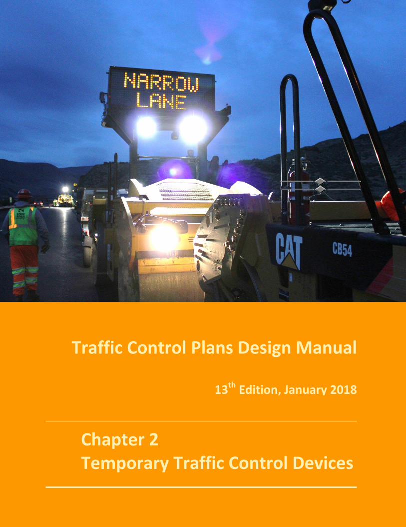
Traffic Control Plans Design Manual
13th Edition, January 2018
Chapter 2 Temporary Traffic Control Devices
Traffic Control Plans Design Manual
Oregon Department of Transportation 13th Edition, January 2018 Traffic Control Plans Unit Chapter 2
26
Table of Contents CHAPTER 2 TEMPORARY TRAFFIC CONTROL DEVICES (TCD) ________________ 27
2.0 – KEY TOPICS COVERED IN THIS CHAPTER ________________________________________ 27 2.1 – PURPOSE AND PRINCIPLES OF TCD ___________________________________________ 27 2.2 – CRASHWORTHY DEVICES ___________________________________________________ 28
2.2.1 - AMERICAN TRAFFIC SAFETY SERVICES ASSOCIATION (ATSSA) ____________________ 29 2.3 – CATEGORY 1 DEVICES ______________________________________________________ 30
2.3.1 - TUBULAR AND CONICAL MARKERS ________________________________________ 30 2.3.2 - TEMPORARY PLASTIC DRUMS ____________________________________________ 31 2.3.3 - TEMPORARY DELINEATORS ______________________________________________ 31 2.3.4 - TEMPORARY PAVEMENT MARKINGS & MARKERS _____________________________ 32
2.4 – CATEGORY 2 DEVICES ______________________________________________________ 37 2.4.1 - TYPE I, II AND III BARRICADES _____________________________________________ 37 2.4.2 – PEDESTRIAN CHANNELIZING DEVICES ______________________________________ 38 2.4.2 – BICYCLE CHANNELIZING DEVICES _________________________________________ 40 2.4.3 - TEMPORARY SIGNS _____________________________________________________ 40 2.4.4 - SIGN SHEETING ________________________________________________________ 41 2.4.5 - SIGN FLAGS AND SIGN FLAG BOARDS ______________________________________ 41 2.4.6 – ROAD WORK XX MPH AND LOOSE GRAVEL XX MPH SIGNS _____________________ 41 2.4.7 - SPECIALTY SIGNS _______________________________________________________ 42 2.4.8 - SIGN SUPPORTS _______________________________________________________ 43
2.5 – CATEGORY 3 DEVICES ______________________________________________________ 45 2.5.1 - TEMPORARY CONCRETE BARRIER _________________________________________ 45 2.5.2 – TEMPORARY STEEL BARRIER _____________________________________________ 47 2.5.3 - TEMPORARY GLARE SHIELDS _____________________________________________ 48 2.5.3 – TEMPORARY GLARE SCREENS ____________________________________________ 48 2.5.4 - REFLECTIVE BARRIER PANELS _____________________________________________ 48 2.5.5 - TEMPORARY IMPACT ATTENUATORS _______________________________________ 49 2.5.6 - TEMPORARY BARRIER, GUARDRAIL CONNECTIONS, AND GUARDRAIL TERMINALS ___ 49 2.5.7 - OTHER BARRIER SYSTEMS _______________________________________________ 50
2.6 – CATEGORY 4 DEVICES ______________________________________________________ 51 2.6.1 - TEMPORARY ELECTRICAL SIGNS ___________________________________________ 51 2.6.2 - TEMPORARY TRAFFIC SIGNALS ____________________________________________ 53 2.6.3 - PORTABLE TRAFFIC SIGNALS _____________________________________________ 54 2.6.4 - FLAGGER STATION LIGHTING _____________________________________________ 54 2.6.5 - AUTOMATED FLAGGER ASSISTANCE DEVICES (AFAD) __________________________ 55
2.7 – SPECIALTY TCD BID ITEMS __________________________________________________ 56 2.7.1 - OVERHEIGHT VEHICLE WARNING SYSTEM (OVWS) ____________________________ 56 2.7.2 – PROTECTIVE NETTING __________________________________________________ 56 2.7.3 - FALSEWORK ILLUMINATION ______________________________________________ 57 2.7.4 - POLE BASE COVERS _____________________________________________________ 57
Traffic Control Plans Design Manual
Oregon Department of Transportation 13th Edition, January 2018 Traffic Control Plans Unit Chapter 2
27
Chapter
2 CHAPTER 2 TEMPORARY TRAFFIC CONTROL DEVICES (TCD)
2.0 – KEY TOPICS COVERED IN THIS CHAPTER Purpose & Principles of Traffic Control Devices (TCD)
Crashworthy Devices
TCD Categories
Detailed Descriptions of TCD
2.1 – PURPOSE AND PRINCIPLES OF TCD The primarily purpose of Traffic Control Devices (TCD) is to provide for the safe movement of traffic through or around the work zone. Safety for roadway users and workers within the work zone is enhanced through uniform usage of TCD. Temporary traffic control devices are used to:
• Regulate • Warn • Guide
When temporary traffic control devices are installed consistently within the work zone, driver expectancy and compliance can be optimized. The consistent and proper application of TCD in the work zone performs two vital functions in a successful work zone:
• Reduce the frequency of crashes • Reduce the severity of crashes
Individuals assigned the responsibility of assuring safe and effective work zones are knowledgeable in the general principles behind temporary traffic control devices.
TCD used in work zones should exhibit the following characteristics. These characteristics are considered key principles for temporary traffic control devices:
1) Fulfill a need 2) Command attention 3) Convey a clear & simple meaning 4) Command respect from road user 5) Give adequate response time
It is imperative TCD are consistent and correctly applied within work zones to provide the road user necessary information to negotiate the work zone safely.
Inappropriate TCD are devices not needed for the current conditions within the work zone, and should be turned away from traffic, covered, or removed from the roadway. Legibility and visibility of the devices should be maintained through the life of the project. Damaged, dirty or improperly functioning devices must be repaired or replaced in a timely manner to maintain their effectiveness.
Traffic Control Plans Design Manual
Oregon Department of Transportation 13th Edition, January 2018 Traffic Control Plans Unit Chapter 2
28
2.2 – CRASHWORTHY DEVICES The Federal Highway Administration (FHWA) policy requires all TCD used in a work zone on the National Highway System (NHS) be crashworthy. FHWA adopted the testing guidelines established by the AASHTO Manual for Assessing Safety Hardware (MASH). The Manual for Assessing Safety Hardware (MASH) is an update to and supersedes NCHRP Report 350, Recommended Procedures for the Safety Performance Evaluation of Highway Features, for the purposes of evaluating new highway safety hardware. An implementation plan for MASH, adopted jointly by AASHTO and FWHA, states that all highway safety hardware accepted prior to the adoption of MASH (January 1, 2010), using criteria contained in NCHRP Report 350, may remain in place and may continue to be manufactured and installed on the NHS. Highway safety hardware accepted using NCHRP Report 350 criteria is not required to be retested using MASH criteria. If a Report 350 approved device is updated or modified, affecting its structural characteristics or its performance (e.g. changes in materials, physical shape, size, weight, etc.), the device may require retesting under the MASH criteria. All new temporary work zone devices manufactured after December 31, 2019 must be successfully crash tested using MASH (2015 Edition). New highway safety hardware not previously evaluated must utilize MASH for testing and evaluation. New MASH testing procedures include changes to design vehicles, variety in barrier design, safety performance, levels of roadway utilization, and criteria for impact severity. It provides a broad range of testing to establish a uniform basis for the application of roadside TCD to the level of use of the particular roadway. All TCD used on Oregon State Highway construction projects must be listed on the ODOT Qualified Products List (QPL). ODOT ensures each device meets the established crashworthy guidelines before a device is used on the NHS. Signal poles are exempt. Each device is reviewed according to the ODOT Product Review Guidelines before the device is deemed Qualified and placed on the QPL. Occasionally, a device is categorized as “Conditional” and placed on the Conditional Use List. The Conditional Use List is used for products that meet established crashworthy guidelines, but when ODOT wants to evaluate the product controlled conditions before moving them onto the Qualified list. A designer or contractor may use devices on the Conditional Use List, but the Project Manager or Contractor may have to conduct a field evaluation. “Crashworthy” means a device has met the established testing and evaluation criteria of MASH (or Report 350 for older or existing devices) and has received a “Letter of Federal-Aid Reimbursement Eligibility” from the FHWA. Work zone traffic control devices have been classified into four categories by the FHWA, each having its own testing requirements.
Category 1 – Low-mass devices with a known performance history. Vendors may self-certify the crashworthiness of these devices. Category 1 devices include tubular markers, conical markers, and plastic drums. Category 2 – Devices with a higher mass and can pose a greater risk to the public if struck. Because of their higher mass, Category 2 devices typically require crash testing (e.g. Barricades, sign supports, and most temporary signing).
Traffic Control Plans Design Manual
Oregon Department of Transportation 13th Edition, January 2018 Traffic Control Plans Unit Chapter 2
29
Category 3 – Category 3 devices pose a more significant risk to the public if not adequately protected or installed correctly. Category 3 devices require more complex crash testing. Examples include impact attenuators, concrete barrier, and guard rail systems, etc. Category 4 – These devices pose the greatest risk to motorists as temporary TCD. Category 4 devices are usually trailer-mounted and should be shielded from traffic, when practical. At a minimum, if used on the roadside and not placed behind a barrier system, these devices should be heavily delineated using other Category 1 and 2 retro-reflective devices. Currently, Category 4 devices do not require crash testing, as FHWA is in the process of developing specific crash testing standards for them.. Examples of Category 4 devices include sequential arrow boards, PCMS, portable traffic signals, and automated flagger assistance devices (AFAD).
Crashworthy Test Level: In general, devices used on State Highways should be tested to the appropriate speeds used on the Highway. It is recommended to use Test Level 3 (TL-3) or higher devices for all highways, regardless of the posted speeds. Test Levels are defined in the AASHTO Roadside Design Guide, NCHRP Report 350, and MASH.
• Test Level 1 (TL-1) devices can be used on highways with speeds of 35 mph or less. • Test Level 2 (TL-2) devices can be used on highways with speeds of 45 mph or less. • Test Level 3 (TL-3) devices are used on highways with speeds greater than 45 mph.
NOTE: Lights are NOT to be added to any channelization device (drums, barricades, etc.) on State Highways. To eliminate the need for large, potentially hazardous batteries, ODOT does not include supplemental warning light devices on its portable channelization devices.
2.2.1 - AMERICAN TRAFFIC SAFETY SERVICES ASSOCIATION (ATSSA) The ATSSA Quality Guidelines for Temporary Traffic Control Devices and Features is a set of guidelines users should refer to in evaluating the condition of TCDs in the field. The ATSSA Guidelines are included in the ODOT/APWA Standard Specifications, and on ODOT highway construction projects, the contractor is contractually obligated to use devices that meet these guidelines. Current specification requirements call for the use of new or “Acceptable” TCD for all installations. In the field, TCD not meeting the “Acceptable” criteria as described in the ATSSA Guidelines, should be replaced with devices that do.
Traffic Control Plans Design Manual
Oregon Department of Transportation 13th Edition, January 2018 Traffic Control Plans Unit Chapter 2
30
2.3 – CATEGORY 1 DEVICES CATEGORY 1
Self-Certified Crashworthy Examples of Devices Included
• Lightweight devices < 100 lbs. • No potential for device to penetrate
vehicle windshield or cabin • No significant effect on control or
trajectory of an impacted vehicle
• Tubular and Conical Markers • Plastic Drums • Temporary Delineators • Pavement Markers
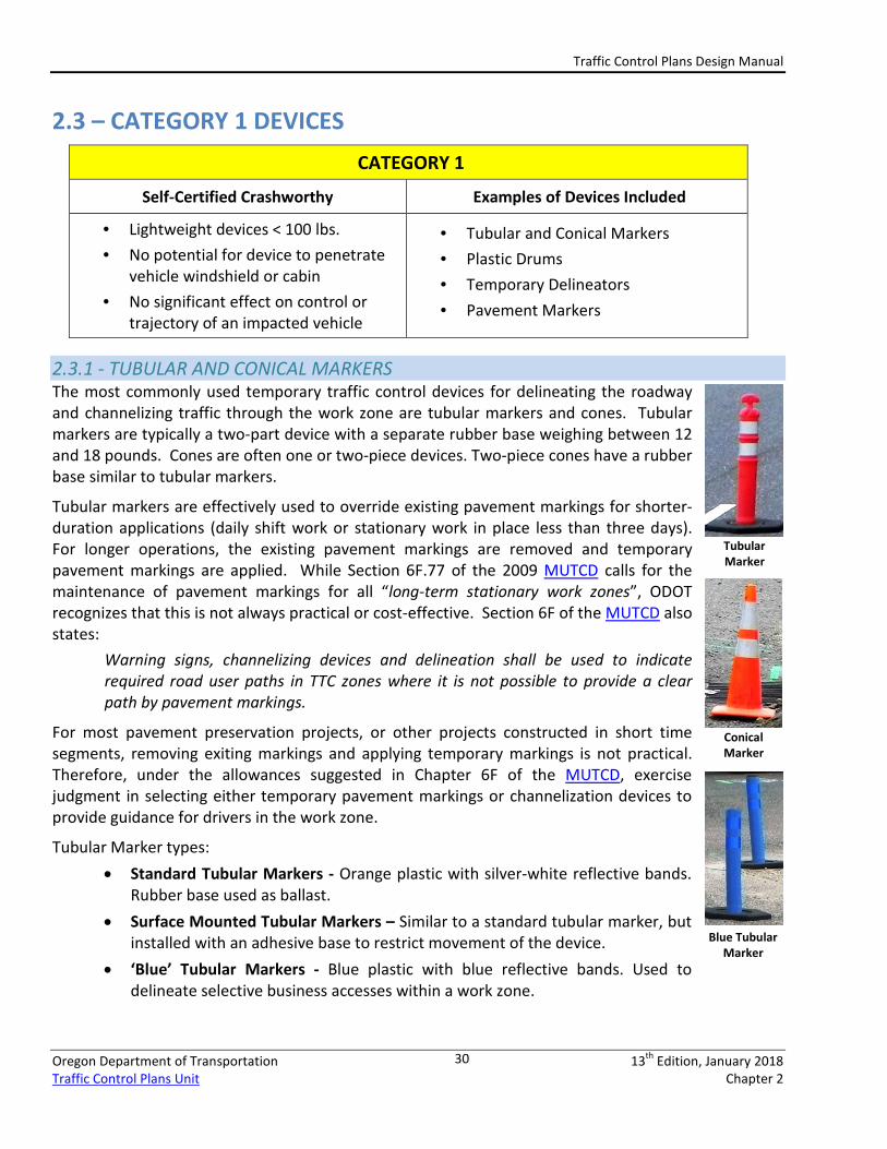
2.3.1 - TUBULAR AND CONICAL MARKERS The most commonly used temporary traffic control devices for delineating the roadway and channelizing traffic through the work zone are tubular markers and cones. Tubular markers are typically a two-part device with a separate rubber base weighing between 12 and 18 pounds. Cones are often one or two-piece devices. Two-piece cones have a rubber base similar to tubular markers.
Tubular markers are effectively used to override existing pavement markings for shorter-duration applications (daily shift work or stationary work in place less than three days). For longer operations, the existing pavement markings are removed and temporary pavement markings are applied. While Section 6F.77 of the 2009 MUTCD calls for the maintenance of pavement markings for all “long-term stationary work zones”, ODOT recognizes that this is not always practical or cost-effective. Section 6F of the MUTCD also states:
Warning signs, channelizing devices and delineation shall be used to indicate required road user paths in TTC zones where it is not possible to provide a clear path by pavement markings.
For most pavement preservation projects, or other projects constructed in short time segments, removing exiting markings and applying temporary markings is not practical. Therefore, under the allowances suggested in Chapter 6F of the MUTCD, exercise judgment in selecting either temporary pavement markings or channelization devices to provide guidance for drivers in the work zone.
Tubular Marker types: • Standard Tubular Markers - Orange plastic with silver-white reflective bands.
Rubber base used as ballast. • Surface Mounted Tubular Markers – Similar to a standard tubular marker, but
installed with an adhesive base to restrict movement of the device. • ‘Blue’ Tubular Markers - Blue plastic with blue reflective bands. Used to
delineate selective business accesses within a work zone.
Tubular Marker
Conical Marker
Blue Tubular Marker
Traffic Control Plans Design Manual
Oregon Department of Transportation 13th Edition, January 2018 Traffic Control Plans Unit Chapter 2
31
When applied on an ODOT construction project, standard spacing for tubular markers and cones is speed-dependent and are spaced at either 20 or 40 feet apart. At speeds of 45 mph or greater, the 40 ft. spacing is used. For low-speed conditions (< 25 mph) or around intersection and access radii, a spacing of 10 feet is recommended.
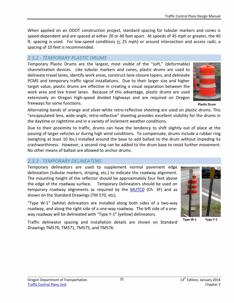
2.3.2 - TEMPORARY PLASTIC DRUMS Temporary Plastic Drums are the largest, most visible of the “soft,” (deformable) channelization devices. Like tubular markers and cones, plastic drums are used to delineate travel lanes, identify work areas, construct lane closure tapers, and delineate PCMS and temporary traffic signal installations. Due to their larger size and higher target value, plastic drums are effective in creating a visual separation between the work area and live travel lanes. Because of this advantage, plastic drums are used extensively on Oregon high-speed divided highways and are required on Oregon freeways for some functions. Alternating bands of orange and silver-white retro-reflective sheeting are used on plastic drums. This “encapsulated lens, wide-angle, retro-reflective” sheeting provides excellent visibility for the drums in the daytime or nighttime and in a variety of inclement weather conditions. Due to their proximity to traffic, drums can have the tendency to shift slightly out of place at the passing of larger vehicles or during high wind conditions. To compensate, drums include a rubber ring (weighing at least 10 lbs.) installed around the base to add ballast to the drum without impeding its crashworthiness. However, a second ring can be added to the drum base to resist further movement. No other means of ballast are allowed to anchor drums.
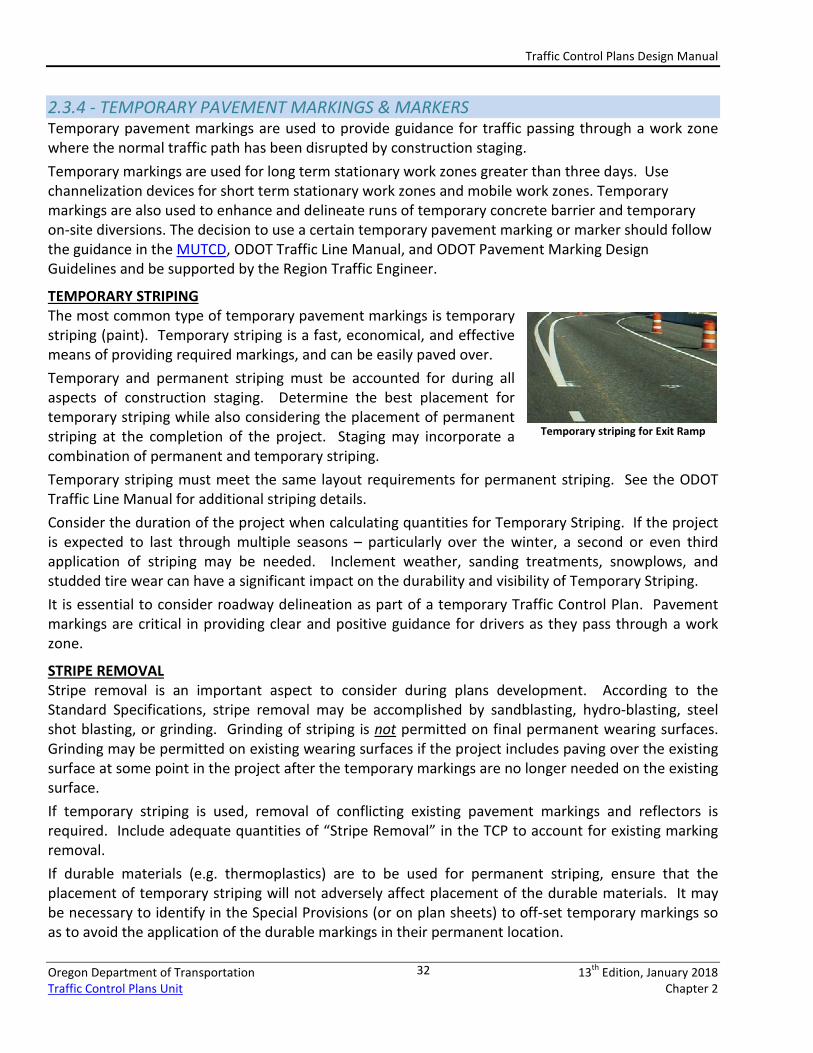
2.3.3 - TEMPORARY DELINEATORS Temporary delineators are used to supplement normal pavement edge delineation (tubular markers, striping, etc.) to indicate the roadway alignment. The mounting height of the reflector should be approximately four feet above the edge of the roadway surface. Temporary Delineators should be used on temporary roadway alignments as required by the MUTCD (Ch. 3F) and as shown on the Standard Drawings (TM 570, etc).
“Type W-1” (white) delineators are installed along both sides of a two-way roadway, and along the right side of a one-way roadway. The left side of a one-way roadway will be delineated with “Type Y-1” (yellow) delineators.
Traffic delineator spacing and installation details are shown on Standard Drawings TM570, TM571, TM575, and TM576.
Type W-1 Type Y-1
Plastic Drum
Traffic Control Plans Design Manual
Oregon Department of Transportation 13th Edition, January 2018 Traffic Control Plans Unit Chapter 2
32
2.3.4 - TEMPORARY PAVEMENT MARKINGS & MARKERS Temporary pavement markings are used to provide guidance for traffic passing through a work zone where the normal traffic path has been disrupted by construction staging. Temporary markings are used for long term stationary work zones greater than three days. Use channelization devices for short term stationary work zones and mobile work zones. Temporary markings are also used to enhance and delineate runs of temporary concrete barrier and temporary on-site diversions. The decision to use a certain temporary pavement marking or marker should follow the guidance in the MUTCD, ODOT Traffic Line Manual, and ODOT Pavement Marking Design Guidelines and be supported by the Region Traffic Engineer.
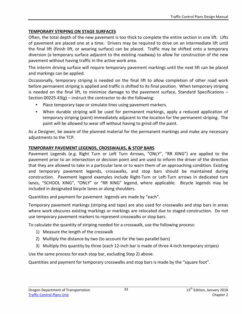
TEMPORARY STRIPING The most common type of temporary pavement markings is temporary striping (paint). Temporary striping is a fast, economical, and effective means of providing required markings, and can be easily paved over. Temporary and permanent striping must be accounted for during all aspects of construction staging. Determine the best placement for temporary striping while also considering the placement of permanent striping at the completion of the project. Staging may incorporate a combination of permanent and temporary striping. Temporary striping must meet the same layout requirements for permanent striping. See the ODOT Traffic Line Manual for additional striping details. Consider the duration of the project when calculating quantities for Temporary Striping. If the project is expected to last through multiple seasons – particularly over the winter, a second or even third application of striping may be needed. Inclement weather, sanding treatments, snowplows, and studded tire wear can have a significant impact on the durability and visibility of Temporary Striping. It is essential to consider roadway delineation as part of a temporary Traffic Control Plan. Pavement markings are critical in providing clear and positive guidance for drivers as they pass through a work zone.
STRIPE REMOVAL Stripe removal is an important aspect to consider during plans development. According to the Standard Specifications, stripe removal may be accomplished by sandblasting, hydro-blasting, steel shot blasting, or grinding. Grinding of striping is not permitted on final permanent wearing surfaces. Grinding may be permitted on existing wearing surfaces if the project includes paving over the existing surface at some point in the project after the temporary markings are no longer needed on the existing surface. If temporary striping is used, removal of conflicting existing pavement markings and reflectors is required. Include adequate quantities of “Stripe Removal” in the TCP to account for existing marking removal. If durable materials (e.g. thermoplastics) are to be used for permanent striping, ensure that the placement of temporary striping will not adversely affect placement of the durable materials. It may be necessary to identify in the Special Provisions (or on plan sheets) to off-set temporary markings so as to avoid the application of the durable markings in their permanent location.
Temporary striping for Exit Ramp
Traffic Control Plans Design Manual
Oregon Department of Transportation 13th Edition, January 2018 Traffic Control Plans Unit Chapter 2
33
TEMPORARY STRIPING ON STAGE SURFACES Often, the total depth of the new pavement is too thick to complete the entire section in one lift. Lifts of pavement are placed one at a time. Drivers may be required to drive on an intermediate lift until the final lift (finish lift, or wearing surface) can be placed. Traffic may be shifted onto a temporary diversion (a temporary surface adjacent to the existing roadway) to allow for construction of the new pavement without having traffic in the active work area. The interim driving surface will require temporary pavement markings until the next lift can be placed and markings can be applied. Occasionally, temporary striping is needed on the final lift to allow completion of other road work before permanent striping is applied and traffic is shifted to its final position. When temporary striping is needed on the final lift, to minimize damage to the pavement surface, Standard Specifications – Section 00225.43(g) – instruct the contractor to do the following:
• Place temporary tape or simulate lines using pavement markers. • When durable striping will be used for permanent markings, apply a reduced application of
temporary striping (paint) immediately adjacent to the location for the permanent striping. The paint will be allowed to wear off without having to grind off the paint.
As a Designer, be aware of the planned material for the permanent markings and make any necessary adjustments to the TCP.
TEMPORARY PAVEMENT LEGENDS, CROSSWALKS, & STOP BARS Pavement Legends (e.g. Right Turn or Left Turn Arrows, “ONLY”, “RR XING”) are applied to the pavement prior to an intersection or decision point and are used to inform the driver of the direction that they are allowed to take in a particular lane or to warn them of an approaching condition. Existing and temporary pavement legends, crosswalks, and stop bars should be maintained during construction. Pavement legend examples include Right-Turn or Left-Turn arrows in dedicated turn lanes, “SCHOOL XING”, “ONLY” or “RR XING” legend, where applicable. Bicycle legends may be included in designated bicycle lanes or along shoulders.
Quantities and payment for pavement legends are made by “each”.
Temporary pavement markings (striping and tape) are also used for crosswalks and stop bars in areas where work obscures existing markings or markings are relocated due to staged construction. Do not use temporary pavement markers to represent crosswalks or stop bars.
To calculate the quantity of striping needed for a crosswalk, use the following process: 1) Measure the length of the crosswalk 2) Multiply the distance by two (to account for the two parallel bars) 3) Multiply this quantity by three (each 12-inch bar is made of three 4-inch temporary stripes)
Use the same process for each stop bar, excluding Step 2) above.
Quantities and payment for temporary crosswalks and stop bars is made by the “square foot”.
Traffic Control Plans Design Manual
Oregon Department of Transportation 13th Edition, January 2018 Traffic Control Plans Unit Chapter 2
34
STRIPING QUANTITIES FOR MULTIPLE SEASON PROJECTS Some construction projects extend through the winter months and must “winter over.” Winters in Oregon can be very harsh on pavement markings, especially in work zones. Consider additional striping quantities when the project is expected to extend into or beyond the winter months, to account for additional applications.
If the project runs for multiple seasons, adjust temporary striping quantities to account for multiple application(s) of temporary striping. The ADT and geographical location of the highway segment can affect the quantities for temporary striping.
DURABLE STRIPING Durable striping (e.g. methyl methacrylate, thermoplastics or other polymer-based products) is used exclusively for permanent striping. When staging traffic from their original lanes to a temporary alignment this striping may conflict with the temporary alignment. In this case, decide which of the following techniques is the safer, more practical and cost-effective method for protecting and guiding traffic:
• Removing the existing durable markings and replacing them later • Covering durable markings with temporary, non-reflective, removable tape (“blackout” tape) • Place channelization devices (cones, tubular markers, drums) to create new lanes for the
shifted traffic A strategy for dealing with durable markings should be based on factors such as duration needed for the temporary markings, quantity of durables in conflict, location of the project, age of the existing durable markings, traffic volumes, and complexity of the temporary traffic shift. Discuss the decision with the Region Construction office and other stakeholders to avoid unnecessary removal of the durable striping.
TEMPORARY TAPE Temporary Tape may be used in lieu of temporary striping. When consideration is needed for damage to the roadway surface, temporary tape can be an excellent alternative material. Temporary tape is commonly applied to concrete roadways, bridge decks or other finished-grade surfaces that are not being overlaid as part of the project. Three classifications of temporary tape exist:
• Removable • Non-Removable • Removable, Non-Reflective (“Blackout”)
Traffic Control Plans Design Manual
Oregon Department of Transportation 13th Edition, January 2018 Traffic Control Plans Unit Chapter 2
35
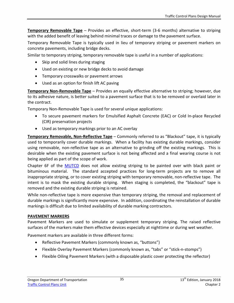
Temporary Removable Tape – Provides an effective, short-term (3-6 months) alternative to striping with the added benefit of leaving behind minimal traces or damage to the pavement surface. Temporary Removable Tape is typically used in lieu of temporary striping or pavement markers on concrete pavements, including bridge decks. Similar to temporary striping, temporary removable tape is useful in a number of applications:
• Skip and solid lines during staging • Used on existing or new bridge decks to avoid damage • Temporary crosswalks or pavement arrows • Used as an option for finish lift AC paving
Temporary Non-Removable Tape – Provides an equally effective alternative to striping; however, due to its adhesive nature, is better suited to a pavement surface that is to be removed or overlaid later in the contract. Temporary Non-Removable Tape is used for several unique applications:
• To secure pavement markers for Emulsified Asphalt Concrete (EAC) or Cold In-place Recycled (CIR) preservation projects
• Used as temporary markings prior to an AC overlay
Temporary Removable, Non-Reflective Tape – Commonly referred to as “Blackout” tape, it is typically used to temporarily cover durable markings. When a facility has existing durable markings, consider using removable, non-reflective tape as an alternative to grinding off the existing markings. This is desirable when the existing pavement surface is not being affected and a final wearing course is not being applied as part of the scope of work. Chapter 6F of the MUTCD does not allow existing striping to be painted over with black paint or bituminous material. The standard accepted practices for long-term projects are to remove all inappropriate striping, or to cover existing striping with temporary removable, non-reflective tape. The intent is to mask the existing durable striping. When staging is completed, the “blackout” tape is removed and the existing durable striping is retained. While non-reflective tape is more expensive than temporary striping, the removal and replacement of durable markings is significantly more expensive. In addition, coordinating the reinstallation of durable markings is difficult due to limited availability of durable marking contractors.
PAVEMENT MARKERS Pavement Markers are used to simulate or supplement temporary striping. The raised reflective surfaces of the markers make them effective devices especially at nighttime or during wet weather.
Pavement markers are available in three different forms: • Reflective Pavement Markers (commonly known as, “buttons”) • Flexible Overlay Pavement Markers (commonly known as, “tabs” or “stick-n-stomps”) • Flexible Oiling Pavement Markers (with a disposable plastic cover protecting the reflector)
Traffic Control Plans Design Manual
Oregon Department of Transportation 13th Edition, January 2018 Traffic Control Plans Unit Chapter 2
36
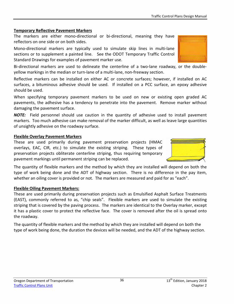
Temporary Reflective Pavement Markers The markers are either mono-directional or bi-directional, meaning they have reflectors on one side or on both sides. Mono-directional markers are typically used to simulate skip lines in multi-lane sections or to supplement a painted line. See the ODOT Temporary Traffic Control Standard Drawings for examples of pavement marker use. Bi-directional markers are used to delineate the centerline of a two-lane roadway, or the double-yellow markings in the median or turn-lane of a multi-lane, non-freeway section. Reflective markers can be installed on either AC or concrete surfaces; however, if installed on AC surfaces, a bituminous adhesive should be used. If installed on a PCC surface, an epoxy adhesive should be used. When specifying temporary pavement markers to be used on new or existing open graded AC pavements, the adhesive has a tendency to penetrate into the pavement. Remove marker without damaging the pavement surface. NOTE: Field personnel should use caution in the quantity of adhesive used to install pavement markers. Too much adhesive can make removal of the marker difficult, as well as leave large quantities of unsightly adhesive on the roadway surface.
Flexible Overlay Pavement Markers These are used primarily during pavement preservation projects (HMAC overlays, EAC, CIR, etc.) to simulate the existing striping. These types of preservation projects obliterate centerline striping, thus requiring temporary pavement markings until permanent striping can be replaced.
The quantity of flexible markers and the method by which they are installed will depend on both the type of work being done and the ADT of highway section. There is no difference in the pay item, whether an oiling cover is provided or not. The markers are measured and paid for as “each”.
Flexible Oiling Pavement Markers: These are used primarily during preservation projects such as Emulsified Asphalt Surface Treatments (EAST), commonly referred to as, “chip seals”. Flexible markers are used to simulate the existing striping that is covered by the paving process. The markers are identical to the Overlay marker, except it has a plastic cover to protect the reflective face. The cover is removed after the oil is spread onto the roadway.
The quantity of flexible markers and the method by which they are installed will depend on both the type of work being done, the duration the devices will be needed, and the ADT of the highway section.
Traffic Control Plans Design Manual
Oregon Department of Transportation 13th Edition, January 2018 Traffic Control Plans Unit Chapter 2
37
2.4 – CATEGORY 2 DEVICES CATEGORY 2
FHWA Crashworthy Examples of Devices Included:
Device is not expected to produce significant vehicular velocity change, but may otherwise be hazardous.
• Barricades – Type I, Type II, and Type III • Pedestrian Channelizing Devices (PCD) • Sign Stands – Portable, TSS, and Posts • Tripod mounted devices
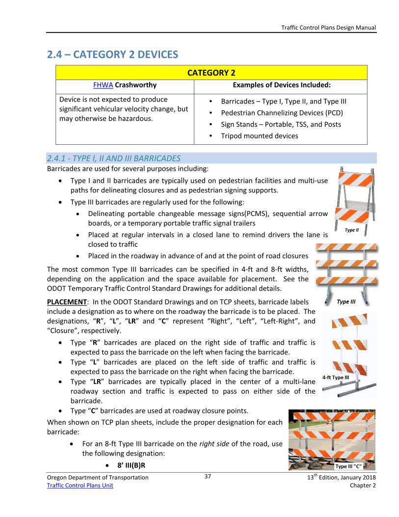
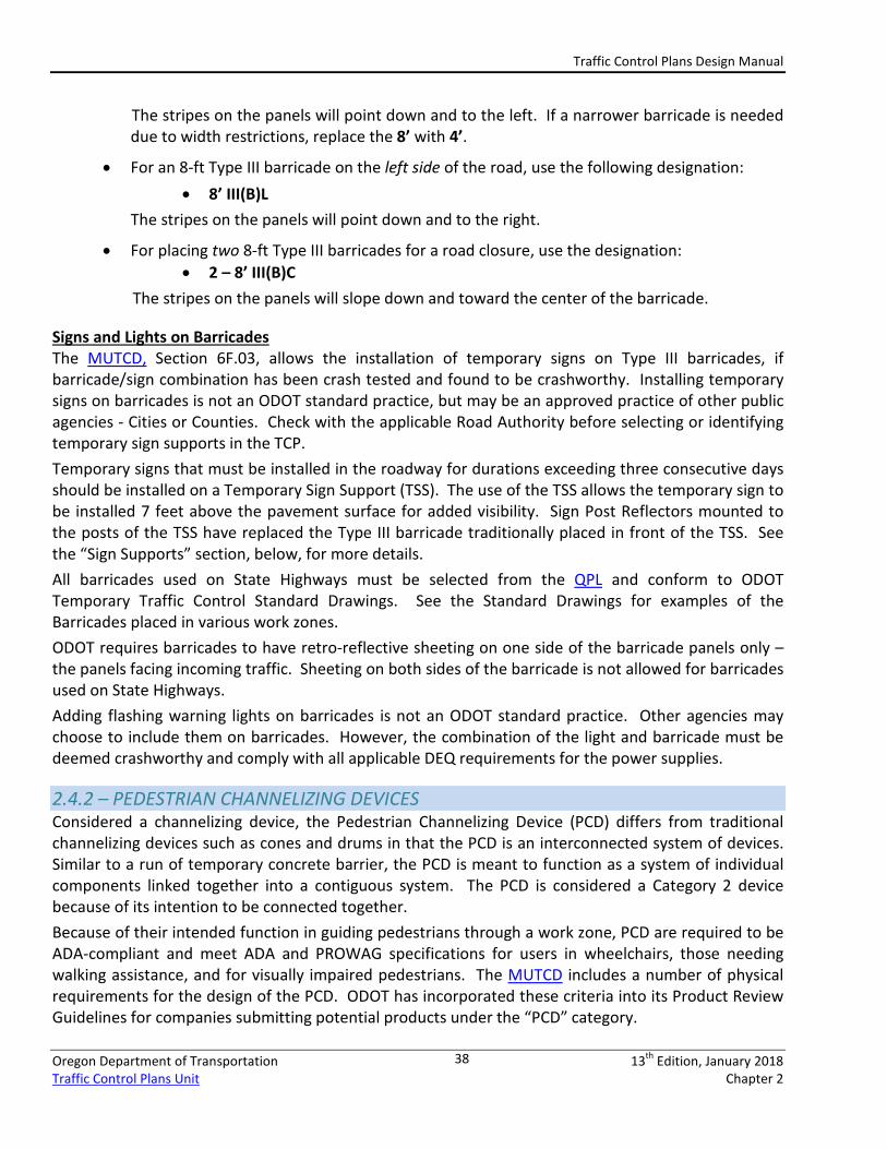
2.4.1 - TYPE I, II AND III BARRICADES Barricades are used for several purposes including:
• Type I and II barricades are typically used on pedestrian facilities and multi-use paths for delineating closures and as pedestrian signing supports.
• Type III barricades are regularly used for the following: • Delineating portable changeable message signs(PCMS), sequential arrow
boards, or a temporary portable traffic signal trailers • Placed at regular intervals in a closed lane to remind drivers the lane is
closed to traffic • Placed in the roadway in advance of and at the point of road closures
The most common Type III barricades can be specified in 4-ft and 8-ft widths, depending on the application and the space available for placement. See the ODOT Temporary Traffic Control Standard Drawings for additional details.
PLACEMENT: In the ODOT Standard Drawings and on TCP sheets, barricade labels include a designation as to where on the roadway the barricade is to be placed. The designations, “R”, “L”, “LR” and “C” represent “Right”, “Left”, “Left-Right”, and “Closure”, respectively.
• Type “R” barricades are placed on the right side of traffic and traffic is expected to pass the barricade on the left when facing the barricade.
• Type “L” barricades are placed on the left side of traffic and traffic is expected to pass the barricade on the right when facing the barricade.
• Type “LR” barricades are typically placed in the center of a multi-lane roadway section and traffic is expected to pass on either side of the barricade.
• Type “C” barricades are used at roadway closure points. When shown on TCP plan sheets, include the proper designation for each barricade:
• For an 8-ft Type III barricade on the right side of the road, use the following designation:
• 8’ III(B)R
Traffic Control Plans Design Manual
Oregon Department of Transportation 13th Edition, January 2018 Traffic Control Plans Unit Chapter 2
38
The stripes on the panels will point down and to the left. If a narrower barricade is needed due to width restrictions, replace the 8’ with 4’.
• For an 8-ft Type III barricade on the left side of the road, use the following designation: • 8’ III(B)L
The stripes on the panels will point down and to the right.
• For placing two 8-ft Type III barricades for a road closure, use the designation: • 2 – 8’ III(B)C
The stripes on the panels will slope down and toward the center of the barricade.
Signs and Lights on Barricades The MUTCD, Section 6F.03, allows the installation of temporary signs on Type III barricades, if barricade/sign combination has been crash tested and found to be crashworthy. Installing temporary signs on barricades is not an ODOT standard practice, but may be an approved practice of other public agencies - Cities or Counties. Check with the applicable Road Authority before selecting or identifying temporary sign supports in the TCP. Temporary signs that must be installed in the roadway for durations exceeding three consecutive days should be installed on a Temporary Sign Support (TSS). The use of the TSS allows the temporary sign to be installed 7 feet above the pavement surface for added visibility. Sign Post Reflectors mounted to the posts of the TSS have replaced the Type III barricade traditionally placed in front of the TSS. See the “Sign Supports” section, below, for more details. All barricades used on State Highways must be selected from the QPL and conform to ODOT Temporary Traffic Control Standard Drawings. See the Standard Drawings for examples of the Barricades placed in various work zones. ODOT requires barricades to have retro-reflective sheeting on one side of the barricade panels only – the panels facing incoming traffic. Sheeting on both sides of the barricade is not allowed for barricades used on State Highways. Adding flashing warning lights on barricades is not an ODOT standard practice. Other agencies may choose to include them on barricades. However, the combination of the light and barricade must be deemed crashworthy and comply with all applicable DEQ requirements for the power supplies.
2.4.2 – PEDESTRIAN CHANNELIZING DEVICES Considered a channelizing device, the Pedestrian Channelizing Device (PCD) differs from traditional channelizing devices such as cones and drums in that the PCD is an interconnected system of devices. Similar to a run of temporary concrete barrier, the PCD is meant to function as a system of individual components linked together into a contiguous system. The PCD is considered a Category 2 device because of its intention to be connected together. Because of their intended function in guiding pedestrians through a work zone, PCD are required to be ADA-compliant and meet ADA and PROWAG specifications for users in wheelchairs, those needing walking assistance, and for visually impaired pedestrians. The MUTCD includes a number of physical requirements for the design of the PCD. ODOT has incorporated these criteria into its Product Review Guidelines for companies submitting potential products under the “PCD” category.
Traffic Control Plans Design Manual
Oregon Department of Transportation 13th Edition, January 2018 Traffic Control Plans Unit Chapter 2
39
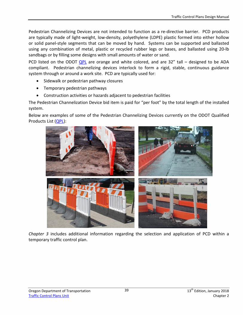
Pedestrian Channelizing Devices are not intended to function as a re-directive barrier. PCD products are typically made of light-weight, low-density, polyethylene (LDPE) plastic formed into either hollow or solid panel-style segments that can be moved by hand. Systems can be supported and ballasted using any combination of metal, plastic or recycled rubber legs or bases, and ballasted using 20-lb sandbags or by filling some designs with small amounts of water or sand. PCD listed on the ODOT QPL are orange and white colored, and are 32” tall – designed to be ADA compliant. Pedestrian channelizing devices interlock to form a rigid, stable, continuous guidance system through or around a work site. PCD are typically used for:
• Sidewalk or pedestrian pathway closures • Temporary pedestrian pathways • Construction activities or hazards adjacent to pedestrian facilities
The Pedestrian Channelization Device bid item is paid for “per foot” by the total length of the installed system. Below are examples of some of the Pedestrian Channelizing Devices currently on the ODOT Qualified Products List (QPL):
Chapter 3 includes additional information regarding the selection and application of PCD within a temporary traffic control plan.
Traffic Control Plans Design Manual
Oregon Department of Transportation 13th Edition, January 2018 Traffic Control Plans Unit Chapter 2
40
2.4.2 – BICYCLE CHANNELIZING DEVICES The Bicycle Channelizing Device (BCD), similar to the Pedestrian Channelizing Device, is intended to be linked together to define a path for bicyclists. A BCD is primarily intended to separate bicycles from active work areas. BCD are not intended to separate bicycle traffic from motor vehicle traffic, as bicycle traffic may need to enter into or cross vehicular traffic to execute a turn or other movement. See Chapter 3 for additional information regarding bicycle accommodations in work zones.
BCD provide continuous delineation and guidance for bicycles – intended to prevent bicyclists from weaving between drums or cones traditionally used to delineate the edge of a work area. Due to their barrier-like structure, BCD should be more effective in keeping bicycles out of the work space, and guiding them along desired pathways. While some BCD can be ballasted with water or sand, they are not intended to redirect traffic. BCD segments are capable of supporting delineator posts, or a breakaway sign support with a temporary sign up to 12inches x 18 inches.
BCD are considered Category 2 devices due to their size and weight and because they are connected together as a system. A BCD does not need to be ADA-compliant, although the designer must consider pedestrian presence within the same space, and include applicable pedestrian accommodations within the design.
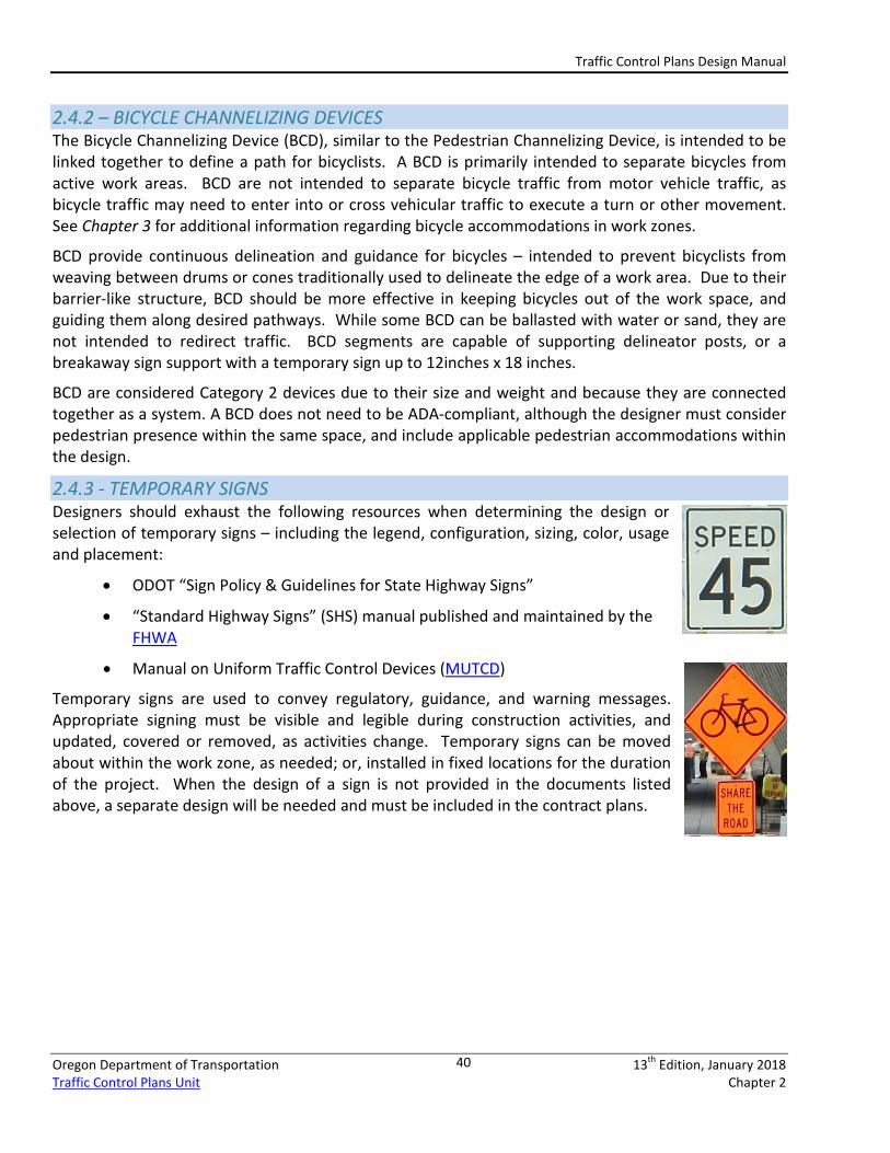
2.4.3 - TEMPORARY SIGNS Designers should exhaust the following resources when determining the design or selection of temporary signs – including the legend, configuration, sizing, color, usage and placement:
• ODOT “Sign Policy & Guidelines for State Highway Signs”
• “Standard Highway Signs” (SHS) manual published and maintained by the FHWA
• Manual on Uniform Traffic Control Devices (MUTCD)
Temporary signs are used to convey regulatory, guidance, and warning messages. Appropriate signing must be visible and legible during construction activities, and updated, covered or removed, as activities change. Temporary signs can be moved about within the work zone, as needed; or, installed in fixed locations for the duration of the project. When the design of a sign is not provided in the documents listed above, a separate design will be needed and must be included in the contract plans.
Traffic Control Plans Design Manual
Oregon Department of Transportation 13th Edition, January 2018 Traffic Control Plans Unit Chapter 2
41
2.4.4 - SIGN SHEETING In designing a TCP, the use of temporary signs is expected. However, a wide variety of temporary signs and sign designs may be used within a traffic control plan and it is important to convey that specific information to the users of the TCP. Within the 2018 Standard Specifications for Construction and the MUTCD, there are sign numbers that are used to describe temporary signs. For example, a “STOP” sign, a “DO NOT PASS” sign, or a “ROAD WORK AHEAD” sign will all be a different color and require different sheetings to build the sign correctly. Use the sign number to determine the sign legend, shape, color, and size.
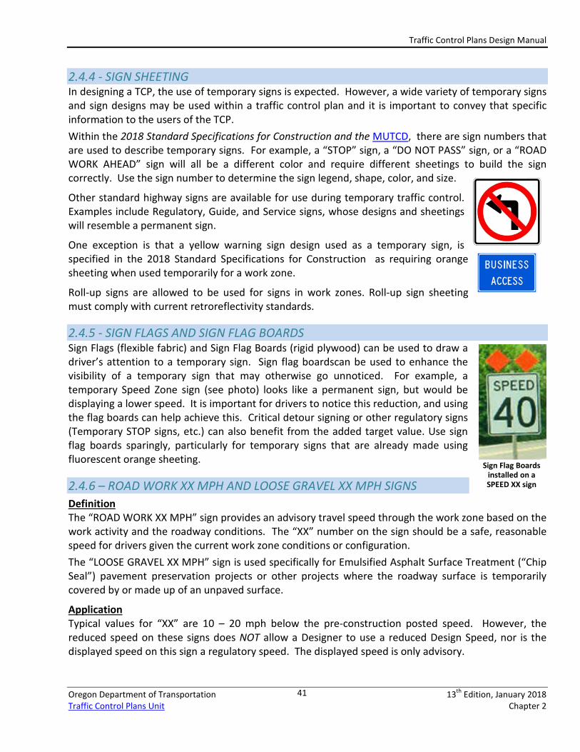
Other standard highway signs are available for use during temporary traffic control. Examples include Regulatory, Guide, and Service signs, whose designs and sheetings will resemble a permanent sign.
One exception is that a yellow warning sign design used as a temporary sign, is specified in the 2018 Standard Specifications for Construction as requiring orange sheeting when used temporarily for a work zone.
Roll-up signs are allowed to be used for signs in work zones. Roll-up sign sheeting must comply with current retroreflectivity standards.
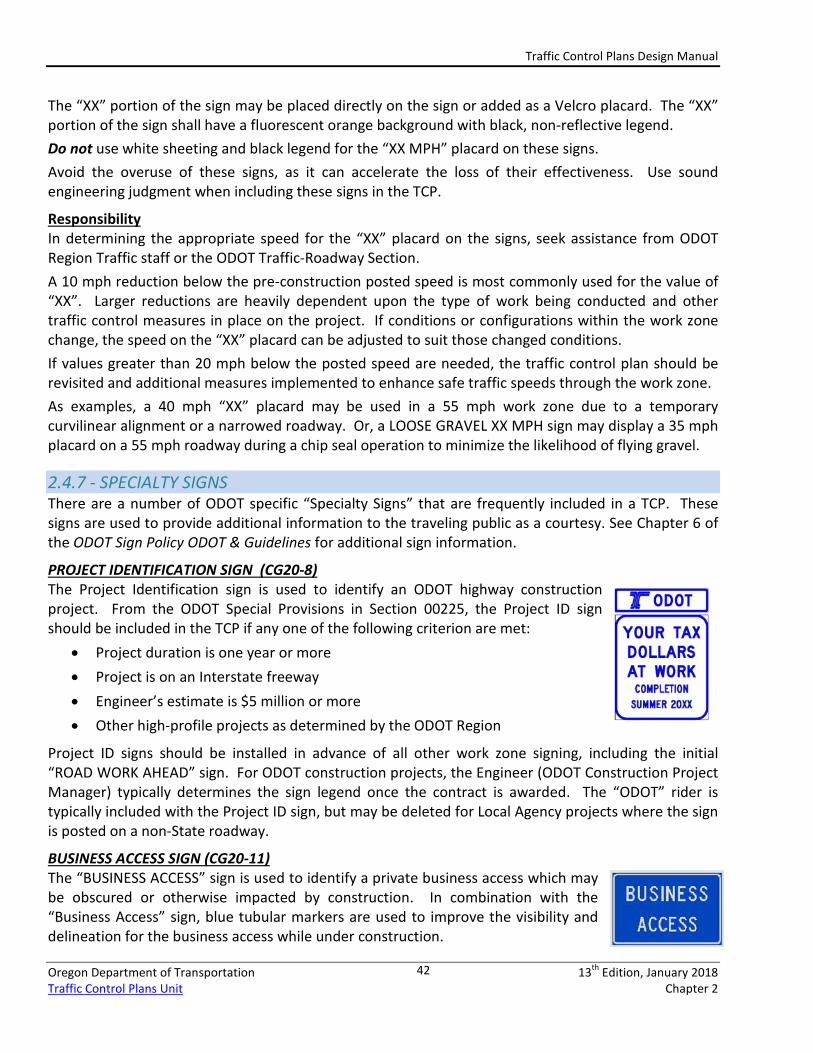
2.4.5 - SIGN FLAGS AND SIGN FLAG BOARDS Sign Flags (flexible fabric) and Sign Flag Boards (rigid plywood) can be used to draw a driver’s attention to a temporary sign. Sign flag boardscan be used to enhance the visibility of a temporary sign that may otherwise go unnoticed. For example, a temporary Speed Zone sign (see photo) looks like a permanent sign, but would be displaying a lower speed. It is important for drivers to notice this reduction, and using the flag boards can help achieve this. Critical detour signing or other regulatory signs (Temporary STOP signs, etc.) can also benefit from the added target value. Use sign flag boards sparingly, particularly for temporary signs that are already made using fluorescent orange sheeting.
2.4.6 – ROAD WORK XX MPH AND LOOSE GRAVEL XX MPH SIGNS Definition The “ROAD WORK XX MPH” sign provides an advisory travel speed through the work zone based on the work activity and the roadway conditions. The “XX” number on the sign should be a safe, reasonable speed for drivers given the current work zone conditions or configuration. The “LOOSE GRAVEL XX MPH” sign is used specifically for Emulsified Asphalt Surface Treatment (“Chip Seal”) pavement preservation projects or other projects where the roadway surface is temporarily covered by or made up of an unpaved surface.
Application Typical values for “XX” are 10 – 20 mph below the pre-construction posted speed. However, the reduced speed on these signs does NOT allow a Designer to use a reduced Design Speed, nor is the displayed speed on this sign a regulatory speed. The displayed speed is only advisory.
Sign Flag Boards installed on a SPEED XX sign
Traffic Control Plans Design Manual
Oregon Department of Transportation 13th Edition, January 2018 Traffic Control Plans Unit Chapter 2
42
The “XX” portion of the sign may be placed directly on the sign or added as a Velcro placard. The “XX” portion of the sign shall have a fluorescent orange background with black, non-reflective legend. Do not use white sheeting and black legend for the “XX MPH” placard on these signs. Avoid the overuse of these signs, as it can accelerate the loss of their effectiveness. Use sound engineering judgment when including these signs in the TCP.
Responsibility In determining the appropriate speed for the “XX” placard on the signs, seek assistance from ODOT Region Traffic staff or the ODOT Traffic-Roadway Section. A 10 mph reduction below the pre-construction posted speed is most commonly used for the value of “XX”. Larger reductions are heavily dependent upon the type of work being conducted and other traffic control measures in place on the project. If conditions or configurations within the work zone change, the speed on the “XX” placard can be adjusted to suit those changed conditions. If values greater than 20 mph below the posted speed are needed, the traffic control plan should be revisited and additional measures implemented to enhance safe traffic speeds through the work zone. As examples, a 40 mph “XX” placard may be used in a 55 mph work zone due to a temporary curvilinear alignment or a narrowed roadway. Or, a LOOSE GRAVEL XX MPH sign may display a 35 mph placard on a 55 mph roadway during a chip seal operation to minimize the likelihood of flying gravel.
2.4.7 - SPECIALTY SIGNS There are a number of ODOT specific “Specialty Signs” that are frequently included in a TCP. These signs are used to provide additional information to the traveling public as a courtesy. See Chapter 6 of the ODOT Sign Policy ODOT & Guidelines for additional sign information.
PROJECT IDENTIFICATION SIGN (CG20-8) The Project Identification sign is used to identify an ODOT highway construction project. From the ODOT Special Provisions in Section 00225, the Project ID sign should be included in the TCP if any one of the following criterion are met:
• Project duration is one year or more • Project is on an Interstate freeway • Engineer’s estimate is $5 million or more • Other high-profile projects as determined by the ODOT Region
Project ID signs should be installed in advance of all other work zone signing, including the initial “ROAD WORK AHEAD” sign. For ODOT construction projects, the Engineer (ODOT Construction Project Manager) typically determines the sign legend once the contract is awarded. The “ODOT” rider is typically included with the Project ID sign, but may be deleted for Local Agency projects where the sign is posted on a non-State roadway.
BUSINESS ACCESS SIGN (CG20-11) The “BUSINESS ACCESS” sign is used to identify a private business access which may be obscured or otherwise impacted by construction. In combination with the “Business Access” sign, blue tubular markers are used to improve the visibility and delineation for the business access while under construction.
Traffic Control Plans Design Manual
Oregon Department of Transportation 13th Edition, January 2018 Traffic Control Plans Unit Chapter 2
43
2.4.8 - SIGN SUPPORTS WOOD SIGN POSTS Wood posts are the most common type of support for temporary signs. Details for the installation of Temporary Signs on wood posts can be found in the ODOT Standard Drawings for Temporary Traffic Control (Series 800) and for Signs, Illumination and Signal Support Structures (Series 600).
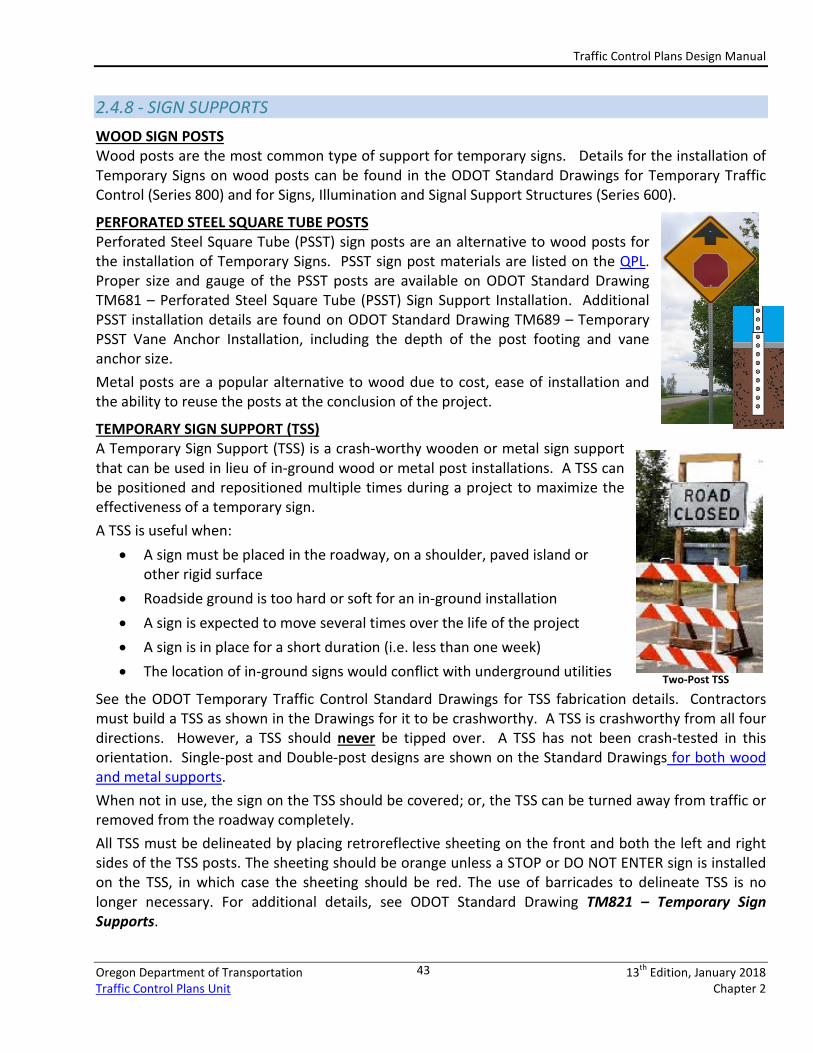
PERFORATED STEEL SQUARE TUBE POSTS Perforated Steel Square Tube (PSST) sign posts are an alternative to wood posts for the installation of Temporary Signs. PSST sign post materials are listed on the QPL. Proper size and gauge of the PSST posts are available on ODOT Standard Drawing TM681 – Perforated Steel Square Tube (PSST) Sign Support Installation. Additional PSST installation details are found on ODOT Standard Drawing TM689 – Temporary PSST Vane Anchor Installation, including the depth of the post footing and vane anchor size. Metal posts are a popular alternative to wood due to cost, ease of installation and the ability to reuse the posts at the conclusion of the project.
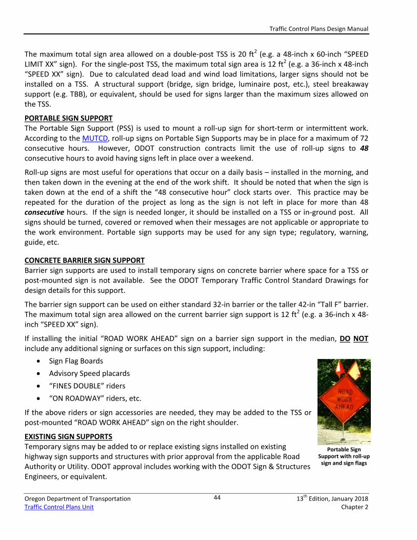
TEMPORARY SIGN SUPPORT (TSS) A Temporary Sign Support (TSS) is a crash-worthy wooden or metal sign support that can be used in lieu of in-ground wood or metal post installations. A TSS can be positioned and repositioned multiple times during a project to maximize the effectiveness of a temporary sign. A TSS is useful when:
• A sign must be placed in the roadway, on a shoulder, paved island or other rigid surface
• Roadside ground is too hard or soft for an in-ground installation • A sign is expected to move several times over the life of the project • A sign is in place for a short duration (i.e. less than one week) • The location of in-ground signs would conflict with underground utilities
See the ODOT Temporary Traffic Control Standard Drawings for TSS fabrication details. Contractors must build a TSS as shown in the Drawings for it to be crashworthy. A TSS is crashworthy from all four directions. However, a TSS should never be tipped over. A TSS has not been crash-tested in this orientation. Single-post and Double-post designs are shown on the Standard Drawings for both wood and metal supports. When not in use, the sign on the TSS should be covered; or, the TSS can be turned away from traffic or removed from the roadway completely. All TSS must be delineated by placing retroreflective sheeting on the front and both the left and right sides of the TSS posts. The sheeting should be orange unless a STOP or DO NOT ENTER sign is installed on the TSS, in which case the sheeting should be red. The use of barricades to delineate TSS is no longer necessary. For additional details, see ODOT Standard Drawing TM821 – Temporary Sign Supports.
Two-Post TSS
Traffic Control Plans Design Manual
Oregon Department of Transportation 13th Edition, January 2018 Traffic Control Plans Unit Chapter 2
44
The maximum total sign area allowed on a double-post TSS is 20 ft2 (e.g. a 48-inch x 60-inch “SPEED LIMIT XX” sign). For the single-post TSS, the maximum total sign area is 12 ft2 (e.g. a 36-inch x 48-inch “SPEED XX” sign). Due to calculated dead load and wind load limitations, larger signs should not be installed on a TSS. A structural support (bridge, sign bridge, luminaire post, etc.), steel breakaway support (e.g. TBB), or equivalent, should be used for signs larger than the maximum sizes allowed on the TSS.
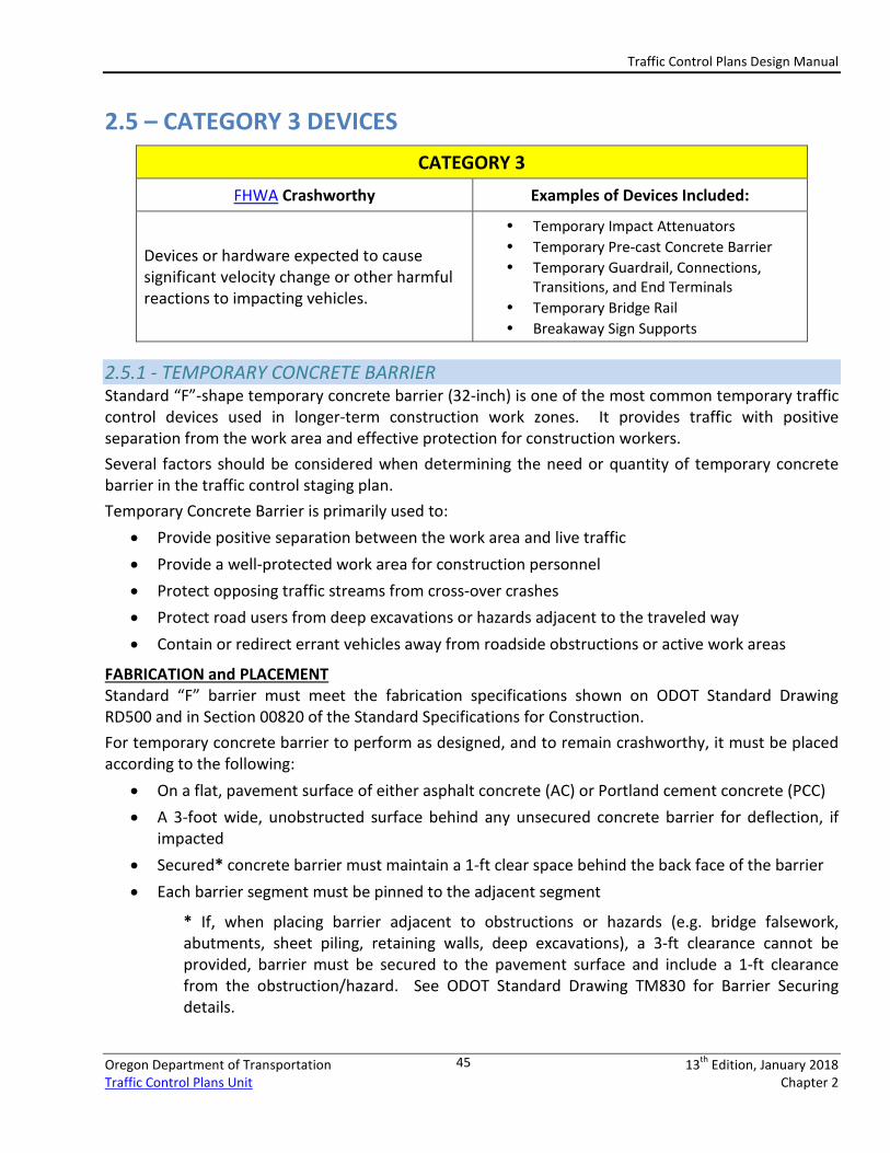
PORTABLE SIGN SUPPORT The Portable Sign Support (PSS) is used to mount a roll-up sign for short-term or intermittent work. According to the MUTCD, roll-up signs on Portable Sign Supports may be in place for a maximum of 72 consecutive hours. However, ODOT construction contracts limit the use of roll-up signs to 48 consecutive hours to avoid having signs left in place over a weekend.
Roll-up signs are most useful for operations that occur on a daily basis – installed in the morning, and then taken down in the evening at the end of the work shift. It should be noted that when the sign is taken down at the end of a shift the “48 consecutive hour” clock starts over. This practice may be repeated for the duration of the project as long as the sign is not left in place for more than 48 consecutive hours. If the sign is needed longer, it should be installed on a TSS or in-ground post. All signs should be turned, covered or removed when their messages are not applicable or appropriate to the work environment. Portable sign supports may be used for any sign type; regulatory, warning, guide, etc.
CONCRETE BARRIER SIGN SUPPORT Barrier sign supports are used to install temporary signs on concrete barrier where space for a TSS or post-mounted sign is not available. See the ODOT Temporary Traffic Control Standard Drawings for design details for this support.
The barrier sign support can be used on either standard 32-in barrier or the taller 42-in “Tall F” barrier. The maximum total sign area allowed on the current barrier sign support is 12 ft2 (e.g. a 36-inch x 48-inch “SPEED XX” sign).
If installing the initial “ROAD WORK AHEAD” sign on a barrier sign support in the median, DO NOT include any additional signing or surfaces on this sign support, including:
• Sign Flag Boards • Advisory Speed placards • “FINES DOUBLE” riders • “ON ROADWAY” riders, etc.
If the above riders or sign accessories are needed, they may be added to the TSS or post-mounted “ROAD WORK AHEAD” sign on the right shoulder.
EXISTING SIGN SUPPORTS Temporary signs may be added to or replace existing signs installed on existing highway sign supports and structures with prior approval from the applicable Road Authority or Utility. ODOT approval includes working with the ODOT Sign & Structures Engineers, or equivalent.
Portable Sign Support with roll-up
sign and sign flags
Traffic Control Plans Design Manual
Oregon Department of Transportation 13th Edition, January 2018 Traffic Control Plans Unit Chapter 2
45
2.5 – CATEGORY 3 DEVICES CATEGORY 3
FHWA Crashworthy Examples of Devices Included:
Devices or hardware expected to cause significant velocity change or other harmful reactions to impacting vehicles.
• Temporary Impact Attenuators • Temporary Pre-cast Concrete Barrier • Temporary Guardrail, Connections,
Transitions, and End Terminals • Temporary Bridge Rail • Breakaway Sign Supports
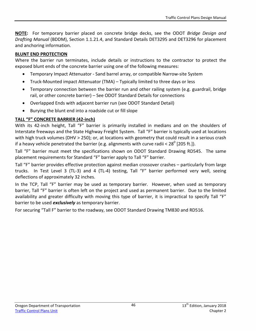
2.5.1 - TEMPORARY CONCRETE BARRIER Standard “F”-shape temporary concrete barrier (32-inch) is one of the most common temporary traffic control devices used in longer-term construction work zones. It provides traffic with positive separation from the work area and effective protection for construction workers. Several factors should be considered when determining the need or quantity of temporary concrete barrier in the traffic control staging plan. Temporary Concrete Barrier is primarily used to:
• Provide positive separation between the work area and live traffic • Provide a well-protected work area for construction personnel • Protect opposing traffic streams from cross-over crashes • Protect road users from deep excavations or hazards adjacent to the traveled way • Contain or redirect errant vehicles away from roadside obstructions or active work areas
FABRICATION and PLACEMENT Standard “F” barrier must meet the fabrication specifications shown on ODOT Standard Drawing RD500 and in Section 00820 of the Standard Specifications for Construction. For temporary concrete barrier to perform as designed, and to remain crashworthy, it must be placed according to the following:
• On a flat, pavement surface of either asphalt concrete (AC) or Portland cement concrete (PCC) • A 3-foot wide, unobstructed surface behind any unsecured concrete barrier for deflection, if
impacted • Secured* concrete barrier must maintain a 1-ft clear space behind the back face of the barrier • Each barrier segment must be pinned to the adjacent segment
* If, when placing barrier adjacent to obstructions or hazards (e.g. bridge falsework, abutments, sheet piling, retaining walls, deep excavations), a 3-ft clearance cannot be provided, barrier must be secured to the pavement surface and include a 1-ft clearance from the obstruction/hazard. See ODOT Standard Drawing TM830 for Barrier Securing details.
Traffic Control Plans Design Manual
Oregon Department of Transportation 13th Edition, January 2018 Traffic Control Plans Unit Chapter 2
46
NOTE: For temporary barrier placed on concrete bridge decks, see the ODOT Bridge Design and Drafting Manual (BDDM), Section 1.1.21.4, and Standard Details DET3295 and DET3296 for placement and anchoring information.
BLUNT END PROTECTION Where the barrier run terminates, include details or instructions to the contractor to protect the exposed blunt ends of the concrete barrier using one of the following measures:
• Temporary Impact Attenuator - Sand barrel array, or compatible Narrow-site System • Truck-Mounted impact Attenuator (TMA) – Typically limited to three days or less • Temporary connection between the barrier run and other railing system (e.g. guardrail, bridge
rail, or other concrete barrier) – See ODOT Standard Details for connections • Overlapped Ends with adjacent barrier run (see ODOT Standard Detail) • Burying the blunt end into a roadside cut or fill slope
TALL “F” CONCRETE BARRIER (42-inch) With its 42-inch height, Tall “F” barrier is primarily installed in medians and on the shoulders of Interstate freeways and the State Highway Freight System. Tall “F” barrier is typically used at locations with high truck volumes (DHV > 250); or, at locations with geometry that could result in a serious crash if a heavy vehicle penetrated the barrier (e.g. alignments with curve radii < 280 [205 ft.]). Tall “F” barrier must meet the specifications shown on ODOT Standard Drawing RD545. The same placement requirements for Standard “F” barrier apply to Tall “F” barrier. Tall “F” barrier provides effective protection against median crossover crashes – particularly from large trucks. In Test Level 3 (TL-3) and 4 (TL-4) testing, Tall “F” barrier performed very well, seeing deflections of approximately 32 inches. In the TCP, Tall “F” barrier may be used as temporary barrier. However, when used as temporary barrier, Tall “F” barrier is often left on the project and used as permanent barrier. Due to the limited availability and greater difficulty with moving this type of barrier, it is impractical to specify Tall “F” barrier to be used exclusively as temporary barrier. For securing “Tall F” barrier to the roadway, see ODOT Standard Drawing TM830 and RD516.
Traffic Control Plans Design Manual
Oregon Department of Transportation 13th Edition, January 2018 Traffic Control Plans Unit Chapter 2
47
2.5.2 – TEMPORARY STEEL BARRIER Temporary steel barrier provides traffic with positive separation from the work area and effective protection for construction workers. Steel barrier is highly portable, and is much easier to move from one location to another due to is lighter weight per foot. Deflections of steel barrier due to impacts vary based on the barrier product and their individual installation and anchoring requirements. Deflection distances must be taken into account if steel barrier is being considered as a positive protection measure within a TCP. Several factors should be considered when determining the need or quantity of temporary steel barrier in the traffic control staging plan. Temporary Steel Barrier is primarily used to:
• Provide positive separation between the work area and live traffic • Provide positive separation between motor vehicle traffic and pedestrians where a temporary
pedestrian pathway must share a portion of the roadway used by motor vehicles. • Provide a protected work space for construction personnel and equipment • Protect adjacent, opposing directions of traffic from cross-over crashes • Protect traffic from deep excavations or hazards adjacent to the traveled way • Contain or redirect errant vehicles away from roadside obstructions or active work areas
PLACEMENT For temporary steel barrier to perform as designed, and to remain crashworthy, it must be placed according to the following:
• Placed on a flat, pavement surface of asphalt concrete (AC) or Portland cement concrete (PCC). • Wide, unobstructed surface behind steel barrier to allow for deflection. Width depends on
steel barrier manufacturer, and method which the barrier is secured to the pavement surface. • A 3-foot wide, unobstructed surface behind any “minimal deflection” installation of steel
barrier to allow for any deflection. • Each barrier piece must be connected to the adjacent segment, per manufacturer instructions.
NOTE: For temporary steel barrier on any bridge decks, see the ODOT Bridge Design and Drafting Manual (BDDM), Section 1.1.21.4, and Standard Details DET3295 and DET3296 for placement information. Contact ODOT Bridge personnel to gain approval to place and anchor any barrier to a ODOT bridge.
BLUNT END PROTECTION Where the barrier run terminates, include details or instructions to the contractor to protect the exposed blunt ends of the steel barrier using one of the following measures:
• Temporary Impact Attenuator - Sand barrel array, or compatible Narrow-site System • Truck-Mounted impact Attenuator (TMA) – Typically limited to three days or less • A temporary connection between the barrier run and other railing system (e.g. guardrail, bridge
rail, or other concrete barrier) – See ODOT Standard Details for connections • Overlapped Ends with adjacent barrier run (see ODOT Standard Detail)
Traffic Control Plans Design Manual
Oregon Department of Transportation 13th Edition, January 2018 Traffic Control Plans Unit Chapter 2
48
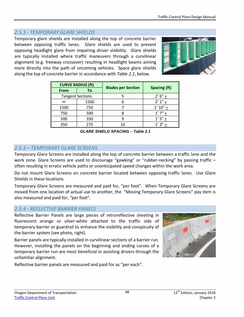
2.5.3 - TEMPORARY GLARE SHIELDS Temporary glare shields are installed along the top of concrete barrier between opposing traffic lanes. Glare shields are used to prevent opposing headlight glare from impairing driver visibility. Glare shields are typically installed where traffic maneuvers through a curvilinear alignment (e.g. freeway crossover) resulting in headlight beams aiming more directly into the path of oncoming vehicles. Space glare shields along the top of concrete barrier in accordance with Table 2.1, below.
CURVE RADIUS (ft) Blades per Section Spacing (ft)
From To Tangent Sections 5 2’ 6” + ∞ 1500 6 2’ 1” +
1500 750 7 1’ 10” + 750 500 8 1’ 7” + 500 350 9 1’ 5” + 350 275 10 1’ 3” +
2.5.3 – TEMPORARY GLARE SCREENS Temporary Glare Screens are installed along the top of concrete barrier between a traffic lane and the work zone. Glare Screens are used to discourage “gawking” or “rubber-necking” by passing traffic – often resulting in erratic vehicle paths or unanticipated speed changes within the work area. Do not mount Glare Screens on concrete barrier located between opposing traffic lanes. Use Glare Shields in these locations. Temporary Glare Screens are measured and paid for, “per foot”. When Temporary Glare Screens are moved from one location of actual use to another, the “Moving Temporary Glare Screens” pay item is also measured and paid for, “per foot”.
2.5.4 - REFLECTIVE BARRIER PANELS Reflective Barrier Panels are large pieces of retroreflective sheeting in fluorescent orange or silver-white attached to the traffic side of temporary barrier or guardrail to enhance the visibility and conspicuity of the barrier system (see photo, right). Barrier panels are typically installed in curvilinear sections of a barrier run. However, installing the panels on the beginning and ending curves of a temporary barrier run are most beneficial in assisting drivers through the unfamiliar alignment. Reflective barrier panels are measured and paid for as ”per each”.
GLARE SHIELD SPACING – Table 2.1
Traffic Control Plans Design Manual
Oregon Department of Transportation 13th Edition, January 2018 Traffic Control Plans Unit Chapter 2
49
2.5.5 - TEMPORARY IMPACT ATTENUATORS Temporary impact attenuators (or, ”crash cushions”) are crashworthy devices that mitigate the effects of errant vehicles striking fixed objects. Temporary impact attenuators, when struck, absorb the energy of the vehicle and dissipate it within the system in various ways – by breaking apart (drum arrays), rapidly collapsing and decelerating (TMAs, gating narrow-site systems), or deflecting slightly and redirecting the errant vehicle (non-gating narrow-site systems). Work zone impact attenuators are listed on the ODOT QPL under “Impact Attenuator, Temporary” and can be separated into the following types:
• Sand Barrel Drum Array – An array of sand-filled plastic drums (modules). See ODOT Temporary Traffic Control Standard Drawings for additional details.
• Narrow-Site Systems – An attenuator style used specifically to protect blunt ends of concrete barrier, bridge rail, columns or other fixed objects within the clear zone with a narrow width (~2-ft). Most narrow-site systems are approximately two-feet wide, making them valuable and practical for protecting traffic where a full-size drum array attenuator will not physically fit. When attaching a narrow-site system to Tall “F” barrier, use a Tall “F” Concrete Barrier Transition to Standard Concrete Barrier (See ODOT Standard Drawing RD 560) and attach the narrow site system to the Standard Concrete Barrier end. Narrow site systems are not designed to attach to Tall “F” Concrete Barrier and can create a snagging hazard.
• Truck Mounted Attenuator (TMA) – A TMA is a mobile impact attenuator attached to a construction vehicle, and is typically used to protect fixed objects, isolated work areas, or other exposed hazards. Because of its portability, a TMA can be used to protect moving work areas or short-duration activities (AC or PCC pavement repairs). A TMA is not intended for long-term protection in a single location, and should be limited to a single location for three consecutive days or less. See Chapter 3 for additional TMA placement guidance and details. See Section 6F.86 of the MUTCD for additional information regarding temporary impact attenuators.
2.5.6 - TEMPORARY BARRIER, GUARDRAIL CONNECTIONS, AND GUARDRAIL TERMINALS Use temporary connections to connect different barrier systems together. Temporary connections may be used as alternatives to impact attenuators, overlapped or buried ends, or other treatments. Several devices are available to connect temporary concrete barrier to other systems including existing barrier, bridge rail and guard rail sections.
BARRIER-TO-GUARDRAIL CONNECTORS Some barrier installations may need to be connected to guardrail or other railing system. This requires a secure connection between the two runs to prevent errant vehicles from snagging the joint between the two systems. See ODOT Standard Drawing RD530 for examples of barrier-to-barrier connections. Temporary Connectors are paid for under the “Temporary Protection & Direction of Traffic” (TP&DT) lump sum pay item. Connectors are measured as “per each”.
Traffic Control Plans Design Manual
Oregon Department of Transportation 13th Edition, January 2018 Traffic Control Plans Unit Chapter 2
50
BRIDGE RAIL CONNECTORS Frequently, bridge rail is terminated by attaching the rail to a run of guardrail to protect the hazard. See ODOT Standard Drawings BR203 for an example of this type of connection. This connection detail may be used for temporary or permanent applications.
GUARDRAIL TERMINALS Guardrail is terminated by using energy absorbing or non-energy absorbing guardrail terminals. Follow the guidance in Roadway Design Manual Chapter 4.6.10 and 4.6.11 and Standard Drawings 420, 425, 430, and 435 to choose guardrail terminals.
2.5.7 - OTHER BARRIER SYSTEMS For work zone activities that are in place for a limited time (< 1 day), there are two additional traffic control devices used for protecting the work area and public traffic.
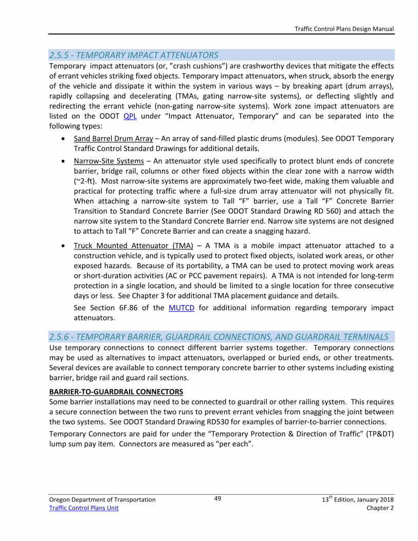
MOVABLE (“ZIPPER”) CONCRETE BARRIER Movable Barrier is typically used for staging projects requiring multiple and frequent moves of the concrete barrier. Movable Barrier is a specially-shaped barrier made of multiple, smaller, interlocked segments. The system is moved using a special transfer machine designed to pick-up, move, and put down the barrier in a single pass. The barrier and machine are included in the contract as a single pay item. Product-specific impact attenuators are used for the Movable Barrier, attach to the end of the barrier run and are moved by the machine in the same manner as the barrier. Movable Concrete Barrier has a slightly higher deflection when struck by an errant vehicle (~ 5-ft, mid-run with unsecured ends). Avoid specifying this barrier system less than 5-feet from a work area or other obstruction. Do not specify moveable barrier as being “secured” to the roadway.
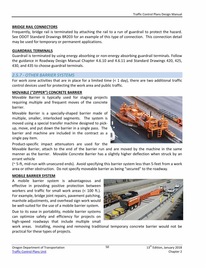
MOBILE BARRIER SYSTEM A mobile barrier system is advantageous and effective in providing positive protection between workers and traffic for small work areas (< 100 ft.). For example, bridge joint repairs, pavement patching, manhole adjustments, and overhead sign work would be well-suited for the use of a mobile barrier system. Due to its ease in portability, mobile barrier systems can optimize safety and efficiency for projects on high-speed roadways that include multiple small work areas. Installing, moving and removing traditional temporary concrete barrier would not be practical for these types of projects.
Traffic Control Plans Design Manual
Oregon Department of Transportation 13th Edition, January 2018 Traffic Control Plans Unit Chapter 2
51
2.6 – CATEGORY 4 DEVICES
2.6.1 - TEMPORARY ELECTRICAL SIGNS SEQUENTIAL ARROW SIGNS Sequential Arrows (arrow boards) are large truck or trailer-mounted lighted signs used to indicate the direction traffic needs to merge as part of a lane closure. Several approved sequential arrows are listed on the ODOT QPL. Sequential arrows shall only be used to indicate a lane closure. Do not use a sequential arrow sign to indicate a traffic shift. Do not use a sequential arrow to indicate a “Keep Left” or “Keep Right” condition. Sequential arrows are measured and paid for as “per each”. See Section 6F.61 of the MUTCD for additional information.
RADAR SPEED TRAILERS Radar speed trailers are trailer-mounted lighted signs used to indicate the speed of vehicles traveling toward the trailer. The trailers are intended to reduce traffic speeds approaching, and as they travel through, a work zone. Radar Speed Trailers are currently available on the ODOT QPL. Radar speed trailers should be setup to allow traffic travelling toward the trailer to clearly see the display panel, similar to a PCMS. The display panel should be programmed to flash the measured speed of the approaching vehicle alternating with a “SLOW DOWN” message when the vehicle’s speed exceeds the speed limit threshold programmed into the Radar Speed Trailer. Current “Unique” Special Provision language for the Radar Speed Trailer includes instructions for determining the speed limit threshold. See the Special Provision “00225 – Radar Speed Trailer” for more details.
The display panel should be programmed to go blank when the measured approach speed of a vehicle exceeds 30 mph above the posted speed limit. This is to discourage drivers from trying to see how high of a speed they can get to display on the panel.
Currently, radar speed trailers are required for paving operations on freeways and expressways as per ODOT Standard Drawing TM880, but may be used elsewhere as designers see fit. Radar speed trailers should not be used at the same location for long periods of time as the effectiveness of the trailers
CATEGORY 4
FHWA Crashworthy or protected Examples of Devices Included:
• Portable, primarily trailer-mounted • Need to be shielded or, at a minimum,
delineated • FHWA continues to monitor in-service
crash performance • MASH encourages the design and
testing of crashworthy versions • Good placement practices
• Sequential Arrows (‘Arrow Boards’)
• Portable Changeable Message Signs (PCMS)
• Automated Flagger Assistance Devices (AFAD)Portable Traffic Signals
• Portable Light Plants (Not flagger station lighting)
Traffic Control Plans Design Manual
Oregon Department of Transportation 13th Edition, January 2018 Traffic Control Plans Unit Chapter 2
52
fades over time. Radar speed trailers are measured and paid for as “per each”. See Section 2L and 6F.60 of the MUTCD for additional information.
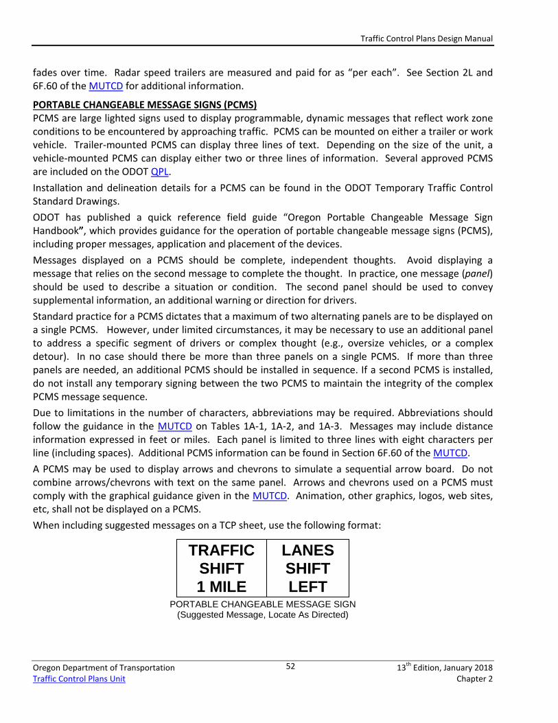
PORTABLE CHANGEABLE MESSAGE SIGNS (PCMS) PCMS are large lighted signs used to display programmable, dynamic messages that reflect work zone conditions to be encountered by approaching traffic. PCMS can be mounted on either a trailer or work vehicle. Trailer-mounted PCMS can display three lines of text. Depending on the size of the unit, a vehicle-mounted PCMS can display either two or three lines of information. Several approved PCMS are included on the ODOT QPL. Installation and delineation details for a PCMS can be found in the ODOT Temporary Traffic Control Standard Drawings. ODOT has published a quick reference field guide “Oregon Portable Changeable Message Sign Handbook”, which provides guidance for the operation of portable changeable message signs (PCMS), including proper messages, application and placement of the devices. Messages displayed on a PCMS should be complete, independent thoughts. Avoid displaying a message that relies on the second message to complete the thought. In practice, one message (panel) should be used to describe a situation or condition. The second panel should be used to convey supplemental information, an additional warning or direction for drivers. Standard practice for a PCMS dictates that a maximum of two alternating panels are to be displayed on a single PCMS. However, under limited circumstances, it may be necessary to use an additional panel to address a specific segment of drivers or complex thought (e.g., oversize vehicles, or a complex detour). In no case should there be more than three panels on a single PCMS. If more than three panels are needed, an additional PCMS should be installed in sequence. If a second PCMS is installed, do not install any temporary signing between the two PCMS to maintain the integrity of the complex PCMS message sequence. Due to limitations in the number of characters, abbreviations may be required. Abbreviations should follow the guidance in the MUTCD on Tables 1A-1, 1A-2, and 1A-3. Messages may include distance information expressed in feet or miles. Each panel is limited to three lines with eight characters per line (including spaces). Additional PCMS information can be found in Section 6F.60 of the MUTCD. A PCMS may be used to display arrows and chevrons to simulate a sequential arrow board. Do not combine arrows/chevrons with text on the same panel. Arrows and chevrons used on a PCMS must comply with the graphical guidance given in the MUTCD. Animation, other graphics, logos, web sites, etc, shall not be displayed on a PCMS. When including suggested messages on a TCP sheet, use the following format:
PORTABLE CHANGEABLE MESSAGE SIGN (Suggested Message, Locate As Directed)
TRAFFIC SHIFT 1 MILE
LANES SHIFT LEFT
Traffic Control Plans Design Manual
Oregon Department of Transportation 13th Edition, January 2018 Traffic Control Plans Unit Chapter 2
53
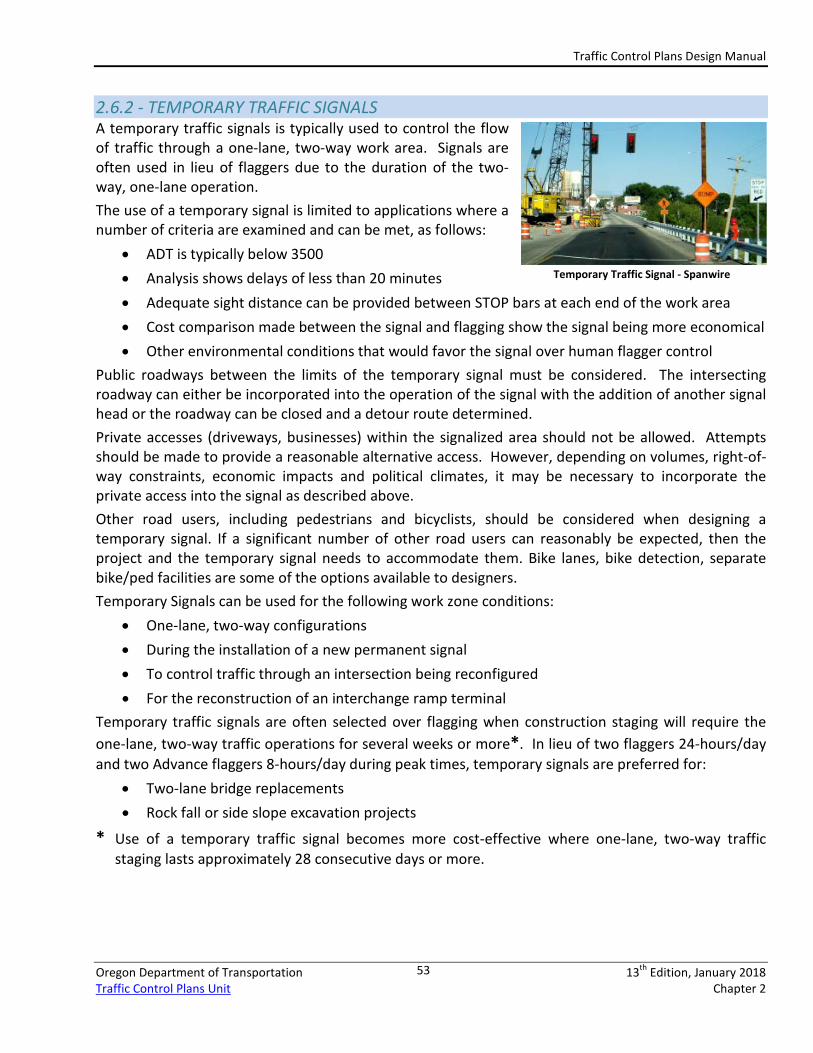
2.6.2 - TEMPORARY TRAFFIC SIGNALS A temporary traffic signals is typically used to control the flow of traffic through a one-lane, two-way work area. Signals are often used in lieu of flaggers due to the duration of the two-way, one-lane operation. The use of a temporary signal is limited to applications where a number of criteria are examined and can be met, as follows:
• ADT is typically below 3500 • Analysis shows delays of less than 20 minutes • Adequate sight distance can be provided between STOP bars at each end of the work area • Cost comparison made between the signal and flagging show the signal being more economical • Other environmental conditions that would favor the signal over human flagger control
Public roadways between the limits of the temporary signal must be considered. The intersecting roadway can either be incorporated into the operation of the signal with the addition of another signal head or the roadway can be closed and a detour route determined. Private accesses (driveways, businesses) within the signalized area should not be allowed. Attempts should be made to provide a reasonable alternative access. However, depending on volumes, right-of-way constraints, economic impacts and political climates, it may be necessary to incorporate the private access into the signal as described above. Other road users, including pedestrians and bicyclists, should be considered when designing a temporary signal. If a significant number of other road users can reasonably be expected, then the project and the temporary signal needs to accommodate them. Bike lanes, bike detection, separate bike/ped facilities are some of the options available to designers. Temporary Signals can be used for the following work zone conditions:
• One-lane, two-way configurations • During the installation of a new permanent signal • To control traffic through an intersection being reconfigured • For the reconstruction of an interchange ramp terminal
Temporary traffic signals are often selected over flagging when construction staging will require the one-lane, two-way traffic operations for several weeks or more*. In lieu of two flaggers 24-hours/day and two Advance flaggers 8-hours/day during peak times, temporary signals are preferred for:
• Two-lane bridge replacements • Rock fall or side slope excavation projects
* Use of a temporary traffic signal becomes more cost-effective where one-lane, two-way traffic staging lasts approximately 28 consecutive days or more.
Temporary Traffic Signal - Spanwire
Traffic Control Plans Design Manual
Oregon Department of Transportation 13th Edition, January 2018 Traffic Control Plans Unit Chapter 2
54
The design of the temporary signal may be prepared by an ODOT Region Tech Center Signal Designer, a consulting engineer, or by qualified staff within the individual agency. Approval for the installation of a temporary signal on a State highway is granted by the State Traffic Engineer. Similar to a permanent signal, a plan showing the locations of all portable traffic signal equipment, as well as any other traffic control devices to be used in conjunction with the portable traffic signal must be submitted for approval. Approval for temporary signals on city or county roadways is granted by the responsible Traffic Engineer within these individual agencies.
2.6.3 - PORTABLE TRAFFIC SIGNALS Portable traffic signals are temporary traffic signals mounted on a trailer. Portable traffic signals are subject to all of the same requirements for temporary traffic signals, including State Traffic Engineer review and approval. Portable traffic signals should be considered when a temporary signal is needed for a limited duration, ideally less than one month. Portable traffic signals are also ideal when electricity is not readily available. Most portable traffic signals are powered by batteries, recharged by generators or solar panels. Portable traffic signals should not be used at locations where there is more than one travel lane in each direction. However, they may be permissible on divided four-lane roadways, two lanes in each direction, if a separate set of signal heads is provided for each additional travel lane. Portable traffic signals typically should be used at locations where the posted construction speed is less than 35 MPH; however, for limited applications, speeds up to 55 mph may be applicable. When not in use, signal indications and all related traffic control devices should be either removed or covered. Portable traffic signals are no longer limited to two phase operations. Newer signal technologies are allowing multiple phases and wireless connectivity. Under proper conditions, a portable signal can be used at intersections for limited durations. At most intersections, a temporary traffic signal (span wire) is usually a better option. Portable traffic signals must be listed on the ODOT QPL. Refer to the ODOT Traffic Control Plan Standard Drawings for additional guidance as to the layout and additional TCD needed for the signal.
2.6.4 - FLAGGER STATION LIGHTING Flagger Station Lighting shall be reasonably glare-free. Flagger Station Lighting must come from the ODOT QPL. Flagger station lighting illuminates the Flagger during nighttime operations, while minimizing the glare experienced by approaching drivers. Flagger Station Lighting mounted on a trailer does not currently require proof of crashworthiness. Flagger Station Lighting devices mounted on a sign stand, tripod, or other type of potable pole, is considered as a Category 2 device, and proof of crashworthiness is required for inclusion on the QPL and use in an ODOT highway construction contract. Non-crashworthy stand-alone devices purchased prior to January 1, 2014 may still be used through the end of their useful life. The stand-alone flagger station lighting is preferred over the trailer mounted lighting because it is crashworthy, is more portable and mobile than the trailer, and easily transported.
Portable Traffic Signal
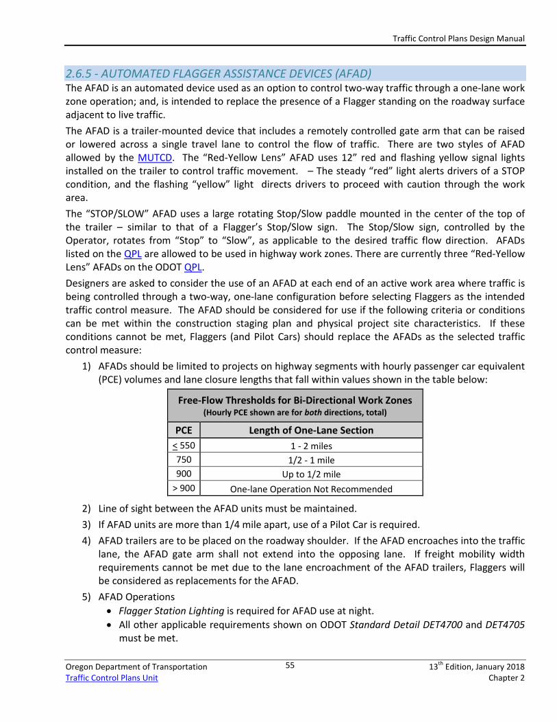
Traffic Control Plans Design Manual
Oregon Department of Transportation 13th Edition, January 2018 Traffic Control Plans Unit Chapter 2
55
2.6.5 - AUTOMATED FLAGGER ASSISTANCE DEVICES (AFAD) The AFAD is an automated device used as an option to control two-way traffic through a one-lane work zone operation; and, is intended to replace the presence of a Flagger standing on the roadway surface adjacent to live traffic. The AFAD is a trailer-mounted device that includes a remotely controlled gate arm that can be raised or lowered across a single travel lane to control the flow of traffic. There are two styles of AFAD allowed by the MUTCD. The “Red-Yellow Lens” AFAD uses 12” red and flashing yellow signal lights installed on the trailer to control traffic movement. – The steady “red” light alerts drivers of a STOP condition, and the flashing “yellow” light directs drivers to proceed with caution through the work area. The “STOP/SLOW” AFAD uses a large rotating Stop/Slow paddle mounted in the center of the top of the trailer – similar to that of a Flagger’s Stop/Slow sign. The Stop/Slow sign, controlled by the Operator, rotates from “Stop” to “Slow”, as applicable to the desired traffic flow direction. AFADs listed on the QPL are allowed to be used in highway work zones. There are currently three “Red-Yellow Lens” AFADs on the ODOT QPL. Designers are asked to consider the use of an AFAD at each end of an active work area where traffic is being controlled through a two-way, one-lane configuration before selecting Flaggers as the intended traffic control measure. The AFAD should be considered for use if the following criteria or conditions can be met within the construction staging plan and physical project site characteristics. If these conditions cannot be met, Flaggers (and Pilot Cars) should replace the AFADs as the selected traffic control measure:
1) AFADs should be limited to projects on highway segments with hourly passenger car equivalent (PCE) volumes and lane closure lengths that fall within values shown in the table below:
Free-Flow Thresholds for Bi-Directional Work Zones (Hourly PCE shown are for both directions, total)
PCE Length of One-Lane Section < 550 1 - 2 miles 750 1/2 - 1 mile 900 Up to 1/2 mile
> 900 One-lane Operation Not Recommended
2) Line of sight between the AFAD units must be maintained. 3) If AFAD units are more than 1/4 mile apart, use of a Pilot Car is required. 4) AFAD trailers are to be placed on the roadway shoulder. If the AFAD encroaches into the traffic
lane, the AFAD gate arm shall not extend into the opposing lane. If freight mobility width requirements cannot be met due to the lane encroachment of the AFAD trailers, Flaggers will be considered as replacements for the AFAD.
5) AFAD Operations • Flagger Station Lighting is required for AFAD use at night. • All other applicable requirements shown on ODOT Standard Detail DET4700 and DET4705
must be met.
Traffic Control Plans Design Manual
Oregon Department of Transportation 13th Edition, January 2018 Traffic Control Plans Unit Chapter 2
56
Designers are encouraged to first consider with a number of application and operational conditions. ODOT has adopted these conditions based on recently published standards and guidance in the 2009 MUTCD. Standard Detail DET4700 and Special Provision language are available and address the use and placement of AFADs within a highway work zone. Review these resources for additional design standard and practice information. See Sections 6E.04 and 6E.05 of the MUTCD for more information regarding AFADs.
NOTE: AFAD use on State Highways differs from the 2009 MUTCD. ODOT disallows the use of AFADs under the following configurations:
• A single AFAD trailer at one end of the work zone operated by a Flagger who is simultaneously flagging traffic at the other end of the work area; and,
• One AFAD Operator controlling two AFAD trailers. ODOT requires one AFAD operator per AFAD trailer for work zones on a State Highway.
2.7 – SPECIALTY TCD BID ITEMS 2.7.1 - OVERHEIGHT VEHICLE WARNING SYSTEM (OVWS) The OVWS is a warning system used to alert over-height vehicles of an upcoming restricted vertical clearance. The device relies on microwave and infrared technologies to signal a vehicle whose physical height exceeds that of the posted height restriction. The OVWS provides both an audible and visual warning. The PCMS displays instructions as to an alternate route around the restriction. The OVWS are most effective on high-volume facilities with a significant percentage of truck traffic. Interstate freight routes are prime facilities. Typically, the request to use this device comes from members of the Project Development Team who are familiar with the construction limitations and the available roadway facilities around the project site. Use OVWS from the QPL.
2.7.2 – PROTECTIVE NETTING Protective netting refers to the material used to protect traffic passing below a bridge under construction. When construction occurs over travel lanes, or when there is the danger of construction equipment, tools, material, or debris falling onto pedestrians or traffic, use protective netting. Protective netting may also be called for on projects where an overhead work area crosses an active stream, creek, river or other body of water. Construction activities using protective netting may include:
• Overpass construction (e.g. deck preparation, rail work, protective fencing, painting, etc.) • Sign bridge construction • Bridge falsework • Bridge maintenance • Tunnel repair/construction
Contact the ODOT Bridge Section to determine design details, measurement/payment, and necessary specifications for protective netting.
Traffic Control Plans Design Manual
Oregon Department of Transportation 13th Edition, January 2018 Traffic Control Plans Unit Chapter 2
57
2.7.3 - FALSEWORK ILLUMINATION Falsework Illumination refers to a temporary lighting system attached to the falsework of a structure under construction, where the falsework is located adjacent to live travel lanes and/or extends over the travel lanes. Falsework Illumination typically consists of a long string of amber-yellow lights framing the falsework portal that traffic passes through. Falsework Illumination is paid for as part of the “Temporary Protection & Direction of Traffic” (TP&DT) lump sum pay item.
2.7.4 - POLE BASE COVERS Pole base covers protect pedestrians from open footing excavations created as part of the installation of a utility pole. Pole base covers are typically comprised of utility grade plywood sheeting. Pole Base Covers are paid for as part of the “Temporary Protection & Direction of Traffic” (TP&DT) lump sum pay item.

Traffic Control Plans Design Manual
Oregon Department of Transportation 13th Edition, January 2018 Traffic Control Plans Unit Chapter 2
58