Embed Size (px)
Citation preview
27
CHAPTER 2
QPSK VARIANT IDENTIFICATION USING BLIND AMR
2. 1 INTRODUCTION
Implementation of advanced information services and systems in
a crowded electromagnetic spectrum is a challenging task for
communication engineers. A spectrum of these signals may range from high
frequency (HF) to millimeter frequency band, and their format can vary
from simple narrowband to wideband scheme. Advanced signal processing
techniques are required for real time signal interception and processing
which are vital for decisions involving operations and tactical actions.
The existence of incompatible wireless standards in different
countries often inhibit deployment of global roaming facilities and
problems in rolling out new service features due to widespread presence of
legacy subscriber handset. The need for ability of radio to operate with all
standards in different geographical regions of the world has fostered the
growth of Software Defined Radio (SDR) concept. SDR technology
promises to solve these problems by implementing the radio functions as
software modules running on generic platform.
The advent of realizable SDR allows implementation of creative
transceiver designs which can dynamically adapt to communication channel
and user application. Instead of dedicated hardware designed to carry out a
rigid set of objectives, software implementation of hardware devices are
entirely flexible regarding their functionality. Supplementary information
28
transmitted is used to reconfigure SDR systems. An ideal use of this
flexible architecture is in the area of wireless networks where a node may
adapt to its environment and user objectives.
Wireless communication system in future will no longer be static
as each individual node in the network will have to acquire a dynamic route
to the intended destination. This dynamic network such as this is not
feasible with existing fixed architecture radio systems. SDR has been a
focal point to cope with the diversification of communication systems. SDR
implementation becomes preferable in maximally flexible systems. One
major advantage resulting from SDR terminal deployment is that, as
network topology changes the terminal can adapt to user requirements,
change the mode of operation, channels and access methods and request
new software upgrades if required without user intervention.
In SDR data communication parameters such as modulation
schemes, bandwidth can be selected on a per packet basis in response to
user constraint such as data rate. This leads to a significant improvement in
bandwidth used and power consumption and minimizing the need for
hardware as in Bose et al (2001). Since a single SDR system robustly
handles multiple modulations, modulation recognition is an important issue
for such system.
The key factor in SDR is the reconfigurable blocks that allow
easy changes in the radio fundamental characteristics such as modulation
type, operating bandwidth, multiple access schemes, source and channel
coding/ decoding methods, frequency spreading/ dispreading techniques,
and encryption/ decryption algorithm. The traditional hardware based radio
requires hardware changes to modify these fundamental characteristics.
29
SDR rapidly evolving as a 4G technology offers flexibility,
global mobility, service portability, wider bandwidth and higher bit rates at
lower cost. It represents a departure from traditional radio design with
reprogrammable radios, opening the way for new services and prolonging
the mobile wireless device lifespan. It consists of a receiver and or
transmitter where the received signal is digitized at some stage downstream
from antenna (digitization may occur at RF, IF or baseband) and then
processed using DSP techniques in flexible and reconfigurable functional
blocks to define the characteristics of the radio.
The general idea behind the SDR architecture is to perform a
considerable amount of signal processing in software instead of being
defined in hardware. This enables the radio to get adapted to change in
environment and user requirements by simply updating the software or by
using adaptable software systems. In such scenarios, a broadcaster could
change the appropriate modulation scheme according to the capacity of the
channel.
The integration of receivers for the software-based radio requires
the modulation identification at the receiver side. Meaning thereby, an
intelligent algorithm identifying the modulation must be running at the
receiver side.
Modulation Classification and Modulation Recognition are
specifically important for SDR which has shown promise to cope with the
variety of communication system. A receiver incorporating AMR will then
have to handle this in real time. This certainly needs identification of
modulation technique for the accurate reception of the signal. Blind
Modulation Recognition techniques can be used with an intelligent receiver
30
yielding an increase in transmission efficiency by reducing overhead as it
does not use any explicit signaling to indicate modulation signal. Current
applications have emerged the need for flexible intelligent communication
systems, where the automatic modulation recognition of the received signal
is a major task.
The task is to identify modulation type used to encode an
unknown radio transmission. The main task of this thesis is to recognize
simultaneously the various linear digital modulation type such as BPSK,
QPSK, OQPSK, 8-PSK and /4- DQPSK. The existing methods require
high SNR, assuming constant signal level and signal parameters are known
to the receiver. Thus the blind identification of modulation schemes like
BPSK, QPSK, OQPSK, 8-PSK and /4- DQPSK that can be desired by a
constellation is being done at lower SNR. The simulations are under taken
at varying SNR, channel model and data rate conditions.
The basic modulation types are identified based on constellation
diagram plotted based on inphase and quadrature phase components. A
further classification of QPSK and OQPSK based on eulidean distance
analysis is done. Further classification of /4-DQPSK and 8-PSK can be
done based on the relative phase difference between the adjacent samples.
2. 2 MODULATION RECOGNITION
HF communication is undergoing resurgence despite advances in
the long-range communication systems. Spectrum surveillance and
spectrum management organizations are monitoring HF spectrum to control
and enforce licensing. It requires a system capable of determining location
of source, separate valid signal from interference and noise and recognizing
31
signal modulation. In past, HF communication employed analog technique
in which signals received by antenna will be down converted to baseband
signals using filters, oscillators and discrete components. This baseband
signal is then passed through demodulator to extract the information
content. Techniques that are monitoring and detecting signals using
traditional methods would require numerous HF receivers, with the prior
knowledge of signals so as to choose the receiver of suitable type for a
bunch of transmitted signals.
In the conventional type of communication system design, the
modulation recognition relied heavily on operator interpretation of
measured parameters to classify the incoming signals. This method requires
information like IF waveform, signal spectrum, instantaneous amplitude
and instantaneous phase from transmitted signal. Here the received signal is
checked and displayed visually. These methods rely very much on the
operator’s skill and abilities. These limitations lead to the development of
more automated modulation recognizers. The later form of recognizer by
Pavlik (2005) and Ghani (1992) uses a bank of demodulators each designed
for a separate modulation type. This is semi-automatic, as an operator is
needed to listen to the output of the demodulator. This approach is, however
not practical anymore owing to the new digital communication techniques
employing RF signals including both data and voice.
A software receiver implementation facilitates much more
flexible and relatively inexpensive application design. This is important for
dynamically changing the function of radio and for reacting to the changes
in the intercepted signal such as the change of the modulation scheme
employed. To detect the received symbols correctly, the receiver has to
know the type of modulation being used in the transmitter. Therefore,
32
automatic detection of correct modulation scheme used in an unknown
received signal is required. After correctly recognizing the modulation
mode of the received signal, parameter estimation and demodulation can be
made further (Nolan et al 2002).
The type of communication modes and number of radio stations
are increasing rapidly in the mobile communication (Mitola 1995). Most of
these systems adopt communication technologies based on digital
modulation schemes. The knowledge on type of modulation scheme
provides valuable information and is crucial in retrieving the information
stored in the signal. Therefore efficient methods to discriminate them have
to be sort out. However, new transmission receiver systems need to classify
automatically digital modulation without specific information of the
transmitted signal. The efficient modulation detection schemes can provide
an insight into the channel and noise characteristics of the propagating
medium.
Digitally modulated signal like QPSK and its variants (OQPSK,
/4–DQPSK, 8-PSK) are employed for mobile and wireless communication
standards like IS-54, IS-95, IS-136, TETRA and 802.11. Such signals can
be found in interference identification and spectrum management,
identification of non-licensed transmitters, electronic warfare, surveillance
and threat analysis, control of communication quality etc. In
Communication Intelligence (COMINT) applications, the modulation types
are considered as signal signatures, Le Guen and Mansour (2002). A
practical SDR system needs automatic distinguishing of signals in order to
perform the task of recovering the message properly. Therefore, the
modulation recognition is an essential key to demodulate as well as to
decode and understand the transmitted message.
33
2. 2. 1 Modulation Classification
A modulation classifier is supposed to correctly choose the
modulation format of the incoming signal from a pool of N candidate
modulations. A desirable classifier should provide a high probability of
correct classification in a short observation interval, particularly for a large
range of SNR. Besides, it should have capabilities to recognize different
modulations in environment with diverse propagation characteristics,
robustness to model mismatches, real time functionality and low
computational complexities.
Automatic Modulation Recognition (AMR) of the detected
signal is an intermediate step between signal detection and demodulation.
Without any fore knowledge of transmitted data and many unknown
parameters at the receiver such as signal power, carrier frequency, phase
offsets, timing information, blind identification of modulation is a difficult
task as indicated by Hanzo et al (2002). This is more challenging in the real
world scenarios with multipath fading, frequency selective and time varying
channels.
According to Soliman and Hsue (1992) the design of a
modulation classifier essentially involves two steps:
Preprocessing the received data which is associated with the noise
removal, estimation of carrier frequency, symbol period, signal and
noise power, and equalization.
The selection and classification of modulation type based on
recognition algorithm.
34
Two methods, namely parameter signaling and blind detection
are being employed for modulation detection. Parameter signaling is where
modulation information is embedded within the transmitted data symbols. It
has the disadvantage of reducing data throughput due to signaling symbols.
In blind detection the estimate of the modulation schemes is done without
explicit signaling. It can be used to minimize the loss of useful data and
conserving the bandwidth. Thus it has the advantage of increased spectral
efficiency and improved throughput over traditional signaling schemes.
There are two approaches in blind identification problem. They are decision
directed and statistical pattern recognition based methods. The first
approach uses the probabilistic and hypothesis testing arguments to
formulate the modulation recognition problem. This approach is based on
the signal envelope characteristics, likelihood ratio, zero crossing, statistical
moments, square law and phase based classifiers. In pattern recognition
method, the classification process follows a step-by-step procedure of
feature extraction, reduction of feature space and classification based on
lower dimension feature space subsystem.
The objective of blind modulation detection is to determine the
type of modulation used within the information conveyed by the least
possible number of received samples. The empirical data provided by the
received noisy samples is the distance to the closest legitimate constellation
point of all the modulation schemes. In other words, given a noisy sample
there would be M errors where M is the number of modulation schemes
used. Therefore, the objective is to make use of the distribution of these
data or errors to make a statistical inference of the type of modulation used.
35
2. 3 SIGNAL MODEL AND CHANNEL MODEL
To transmit digital information on bandpass channels, sinusoidal
carrier is required to perform frequency translation of the transmitted signal
spectrum. By Chen et al (2005), a modulated signal can be expressed as,
cs t m t f t (2.1)
where exp 2 cf t --- complex carrier signal with frequency cf
m t --- complex envelope containing the message signal
j tm t a t e (2.2)
Re--- real apart
The modulated signal can also be represented in the form of
inphase (I) and quadrature phase (Q) components as
=I cos 2 cos 2c cs t t f t Q t f t (2.3)
Amplitude of message signal is given by
a t = 2 2m t Q t I t (2.4)
Phase of message signal can be calculated as
t = 1tan IQ tz t t (2.5)
The channel over which bandpass signal s(t), is transmitted and
received as bandpass waveform r(t) can be modeled as follows:
AWGN Channel
Rayleigh fading Channel
2. 3. 1 Additive White Gaussian Noise Channel (AWGN)
The most important and most analyzed digital communication
channel in practice is the AWGN channel. The output of the channel r(t) is
36
n(t)
r (t) s (t)
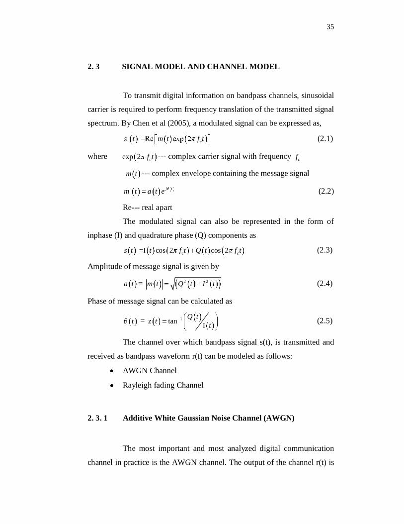
the sum of modulated signal s(t) and an uncorrelated gaussian noise n(t), as
shown in Figure 2.1. On transmission through the channel, noise gets
added to the transmitted signal so the received signal takes the form,
r t s t n t (2.6)
where n t --- channel noise
s t --- transmitted signal
The added noise is assumed to be uncorrelated with itself, as it is
white in nature. AWGN has the following characteristics (Haykins 1994):
Mean of noise signal is zero.
0E n t (2.7)
where E{.} --- Expectation
Auto correlation function of the noise is
* ( ) 2oE n t n t T N T (2.8)
Where 2oN --- Power spectral density of noise signal
----impulse function/ dirac delta function
By taking the mean of the received signal, the originally
transmitted signal is recovered, since the mean of the added noise is zero.
Figure 2.1 Model of AWGN Channel
2. 3. 2 Rayleigh Fading Channel
In a radio link, the RF signal from the transmitter may be
reflected from objects such as hills, buildings, walls or vehicles. Some of
37
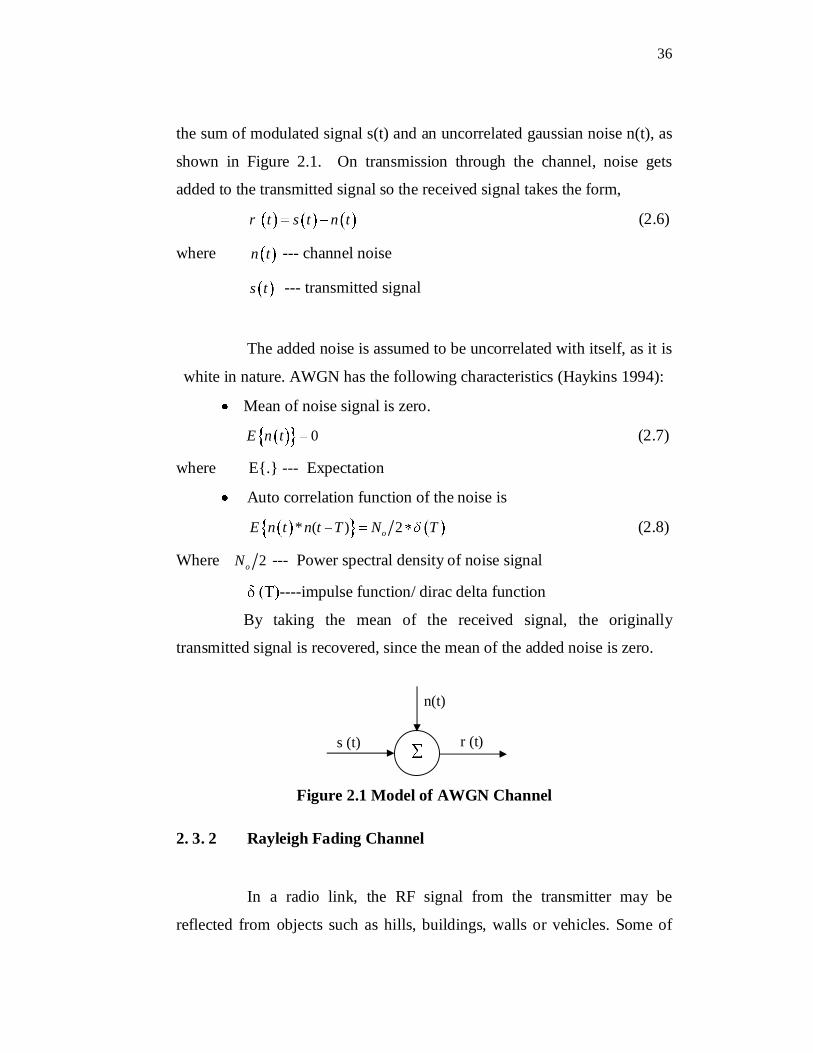
these reflections will arrive at the receiver, giving rise to multiple
transmission paths at the receiver. Figure 2.2 shows some of the possible
ways in which multipath signals can occur. Each multipath signal will have
different propagation distance and thus a different phase rotation. The
relative phase of multiple reflected signals can cause constructive or
destructive interference at the receiver the mathematical expression of the
received signal r(t) on a Rayleigh fading channel is given by)j t
er t r t e s t n t (2.9)
where n t --- channel noise
s t --- transmitted signal
er --- Rayleigh distributed channel gain
--- uniformly distributed phase
This is experienced over very short distances (typically at half
wavelength distances), thus is given the name fast fading as told by
Rappaport ( 2002).
Figure 2.2 Model of Rayleigh fading channel
38
2. 4 MODULATION TECHNIQUES
Modulation in the context of radio communication is a process of
varying some characteristics of a high frequency carrier wave with respect
to information signal in order to transmit it over a long communication
channel. A radio transmitter modulates the carrier signal before it is being
transmitted and the receiver performs a demodulation in order to restore the
baseband signal. The modulation can be classified as analog and digital
modulation based on the nature of carrier signal.
2. 4. 1 Digital Modulation
The advances over the last several decades in hardware and
digital signal processing have made digital transceivers much cheaper,
faster, and more power efficient than analog transceivers. Digital
modulation is the mapping of information bits into an analog signal for
transmission over the channel. Digital modulation offers the following
advantages over analog scheme:
High data rate
High spectral efficiency (minimum bandwidth occupancy)
High power efficiency (minimum required transmit power)
Robustness to channel impairments (minimum probability of bit
error)
Effective multiple access storages
Low power/ cost implementation
Powerful error correction techniques
Better data security and privacy
39
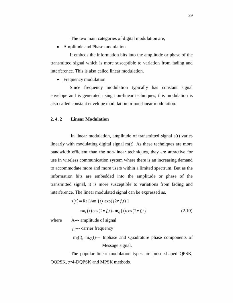
The two main categories of digital modulation are,
Amplitude and Phase modulation
It embeds the information bits into the amplitude or phase of the
transmitted signal which is more susceptible to variation from fading and
interference. This is also called linear modulation.
Frequency modulation
Since frequency modulation typically has constant signal
envelope and is generated using non-linear techniques, this modulation is
also called constant envelope modulation or non-linear modulation.
2. 4. 2 Linear Modulation
In linear modulation, amplitude of transmitted signal s(t) varies
linearly with modulating digital signal m(t). As these techniques are more
bandwidth efficient than the non-linear techniques, they are attractive for
use in wireless communication system where there is an increasing demand
to accommodate more and more users within a limited spectrum. But as the
information bits are embedded into the amplitude or phase of the
transmitted signal, it is more susceptible to variations from fading and
interference. The linear modulated signal can be expressed as,
s t Re [ m t exp( 2 ) ] cA j f t
= t cos 2 - m t cos 2I c Q cm f t f t (2.10)
where A--- amplitude of signal
cf --- carrier frequency
mI(t), mQ(t)--- Inphase and Quadrature phase components of
Message signal.
The popular linear modulation types are pulse shaped QPSK,
OQPSK, /4-DQPSK and MPSK methods.
40
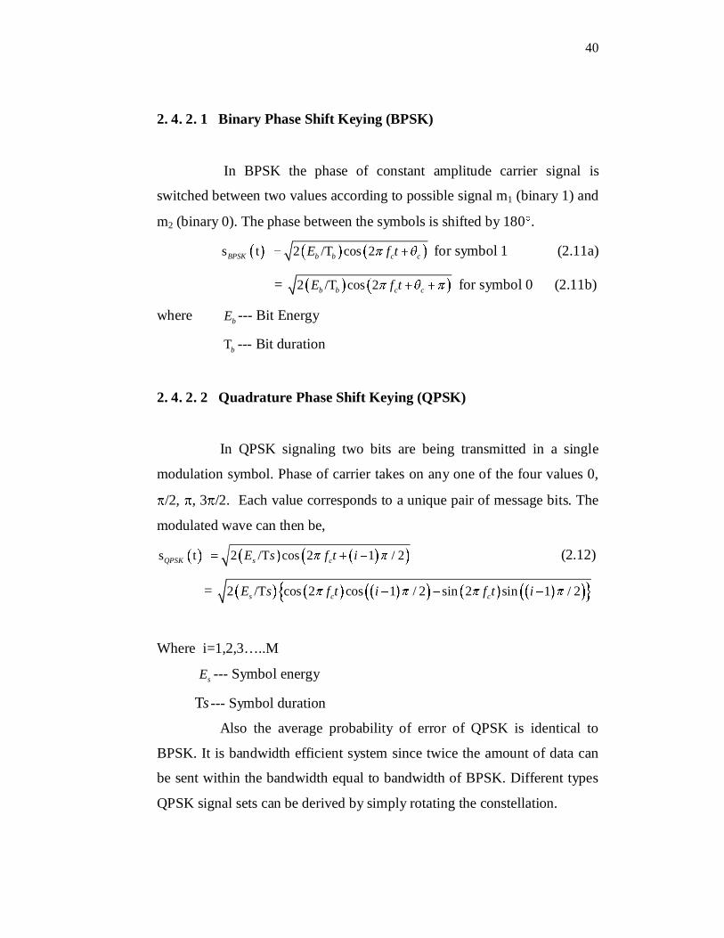
2. 4. 2. 1 Binary Phase Shift Keying (BPSK)
In BPSK the phase of constant amplitude carrier signal is
switched between two values according to possible signal m1 (binary 1) and
m2 (binary 0). The phase between the symbols is shifted by 180 .
s t 2 /T cos 2BPSK b b c cE f t for symbol 1 (2.11a)
= 2 /T cos 2b b c cE f t for symbol 0 (2.11b)
where bE --- Bit Energy
Tb --- Bit duration
2. 4. 2. 2 Quadrature Phase Shift Keying (QPSK)
In QPSK signaling two bits are being transmitted in a single
modulation symbol. Phase of carrier takes on any one of the four values 0,
/2, , 3 /2. Each value corresponds to a unique pair of message bits. The
modulated wave can then be,
s t 2 /T cos 2 1 / 2QPSK s cE s f t i (2.12)
= 2 /T cos 2 cos 1 / 2 sin 2 sin 1 / 2s c cE s f t i f t i
Where i=1,2,3…..M
sE --- Symbol energy
Ts --- Symbol duration
Also the average probability of error of QPSK is identical to
BPSK. It is bandwidth efficient system since twice the amount of data can
be sent within the bandwidth equal to bandwidth of BPSK. Different types
QPSK signal sets can be derived by simply rotating the constellation.
41
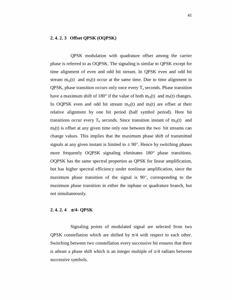
2. 4. 2. 3 Offset QPSK (OQPSK)
QPSK modulation with quadrature offset among the carrier
phase is referred to as OQPSK. The signaling is similar to QPSK except for
time alignment of even and odd bit stream. In QPSK even and odd bit
stream mQ(t) and mI(t) occur at the same time. Due to time alignment in
QPSK, phase transition occurs only once every Ts seconds. Phase transition
have a maximum shift of 180 if the value of both mQ(t) and mI(t) changes.
In OQPSK even and odd bit stream mQ(t) and mI(t) are offset at their
relative alignment by one bit period (half symbol period). Here bit
transitions occur every Tb seconds. Since transition instant of mQ(t) and
mI(t) is offset at any given time only one between the two bit streams can
change values. This implies that the maximum phase shift of transmitted
signals at any given instant is limited to 90 . Hence by switching phases
more frequently OQPSK signaling eliminates 180 phase transitions.
OQPSK has the same spectral properties as QPSK for linear amplification,
but has higher spectral efficiency under nonlinear amplification, since the
maximum phase transition of the signal is 90 , corresponding to the
maximum phase transition in either the inphase or quadrature branch, but
not simultaneously.
2. 4. 2. 4 /4- QPSK
Signaling points of modulated signal are selected from two
QPSK constellation which are shifted by /4 with respect to each other.
Switching between two constellation every successive bit ensures that there
is atleast a phase shift which is an integer multiple of /4 radians between
successive symbols.
42
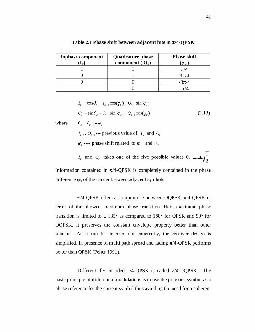
Table 2.1 Phase shift between adjacent bits in /4-QPSK
Inphase component (Ik)
Quadrature phase component ( Qk)
Phase shift( k )
1 1 /4 0 1 3 /40 0 -3 /41 0 - /4
1 1cos cos( ) sin( )k k k k k kI I Q
1 1sin sin( ) cos( )k k k k k kQ I Q (2.13)
where 1k k k
1kI , 1kQ --- previous value of kI and kQ
k ---- phase shift related to Im and Im
kI and kQ takes one of the five possible values 0, 11,2
.
Information contained in /4-QPSK is completely contained in the phase
difference k of the carrier between adjacent symbols.
/4-QPSK offers a compromise between OQPSK and QPSK in
terms of the allowed maximum phase transition. Here maximum phase
transition is limited to 135 as compared to 180 for QPSK and 90 for
OQPSK. It preserves the constant envelope property better than other
schemes. As it can be detected non-coherently, the receiver design is
simplified. In presence of multi path spread and fading /4-QPSK performs
better than QPSK (Feher 1991).
Differentially encoded /4-QPSK is called /4-DQPSK. The
basic principle of differential modulations is to use the previous symbol as a
phase reference for the current symbol thus avoiding the need for a coherent
43
phase reference at the receiver. Specifically, information bits are encoded
with differential phase between current symbol and the previous symbol.
The /4-DQPSK modulation can be achieved by differentially encoding
information bits, yielding to one of the four QPSK constellation points.
Then, every symbol transmission is shifted in phase by /4. This periodic
phase shift has a similar effect as the time offset in OQPSK. It has the
significant advantage of eliminating the need for a coherent phase
reference. It also reduces the amplitude fluctuations at symbol transitions
which makes the signal more robust against noise and fading.
2. 4. 2. 5 Mary PSK (MPSK)
In MPSK the information is encoded in the phase of the
transmitted signal. Thus the transmitted signal over one symbol time is
given as,
s t 2 /T cos 2MPSK s c iE s f t
= 2 /T cos 2 cos sin 2 sins c i c iE s f t f t (2.14)
Where the carrier phase i is given by /12 ii i=1,2,….M
Constellation of MPSK is two-dimensional with M message
points equally spaced on a circle of radius sE centered at origin.
Constellation mapping is usually done by gray encoding where the
messages associated with signal phases that are adjacent to each other differ
by one bit value. In this encoding method, mistaking a symbol for adjacent
one causes a single bit error.
44
2.5 CONSTELLATION SHAPE
Vector space representation of digitally modulated signal
provides a graphical insight into the underlying complex envelope signal
structure of each possible symbol. Constellation diagrams have been the
traditional means for such representations. It is obtained by projecting the
signal on to an orthogonal vector space, the dimensionality of which is
determined by a specific modulation type. From the shape perspective, a
constellation shape can be characterized by a specific and regular pattern of
points on a multi dimensional grid. The constellation is a binary space,
zeros everywhere except on modulation state vectors. The constellation
diagram is the representation of inphase component (I) versus quadrature
component (Q) of complex envelope. The distance between two signals on
a constellation diagram relates how different modulation waveforms are
being differentiated by the receiver among all possible symbols even when
random noise is present.
Some of the properties like probability of error, bandwidth of the
modulation schemes can be inferred from the constellation diagram.
Bandwidth occupied by modulated signal decreases as number of signal
points increases. Therefore if a modulation scheme has a constellation that
is densely packed, it is more efficient than a modulation with sparsely
packed constellation. Probability of error is proportional to the distance
between closest points in a constellation. This implies that a modulation
scheme with a constellation that is densely packed is efficient than a
modulation scheme that has sparse constellation.
The signal space representation of quadrature components of an
intercepted signal is the graphical means of monitoring channel quality
45
variations. Constellation diagrams are commonly used to asses the
underlying signal structure of the received signal. The mean excursion of
the received signal points on the constellation diagram may be used as a
metric to determine whether the employed modulation scheme can be
supported over the time varying channel. Channel distortion resulting in ISI
and fading due to a moving signal source or receiver may also distort the
constellation shape of received signals.
There are three classes of modulation that represent different
geometric approaches to constellation construction.
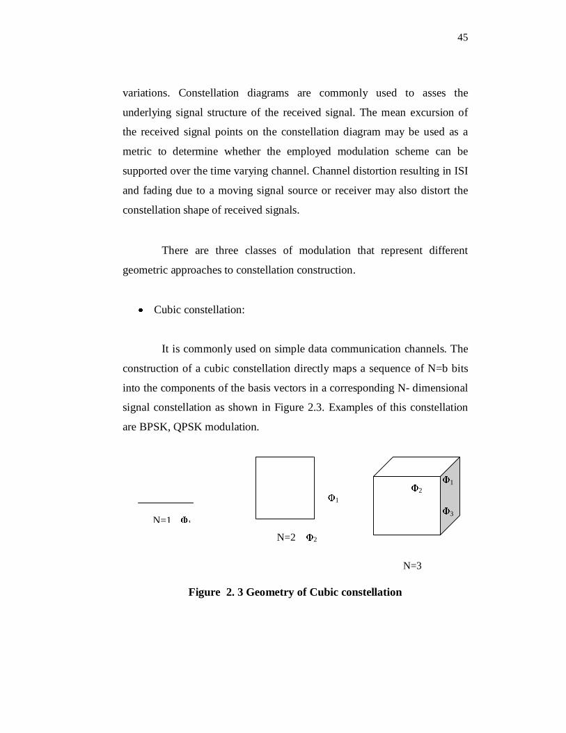
Cubic constellation:
It is commonly used on simple data communication channels. The
construction of a cubic constellation directly maps a sequence of N=b bits
into the components of the basis vectors in a corresponding N- dimensional
signal constellation as shown in Figure 2.3. Examples of this constellation
are BPSK, QPSK modulation.
Figure 2. 3 Geometry of Cubic constellation
N=3 N=1 1
N=2
1
2
1 2
3
N=3
46
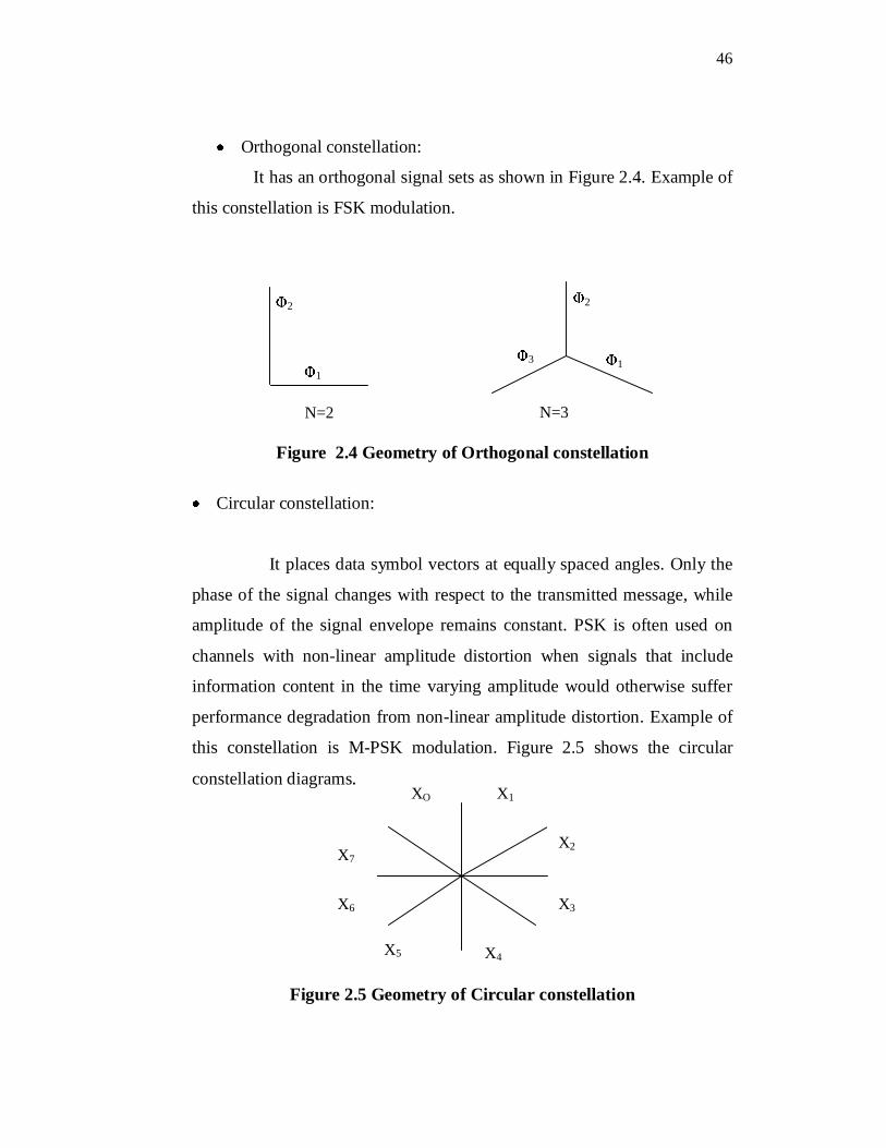
Orthogonal constellation:
It has an orthogonal signal sets as shown in Figure 2.4. Example of
this constellation is FSK modulation.
Figure 2.4 Geometry of Orthogonal constellation
Circular constellation:
It places data symbol vectors at equally spaced angles. Only the
phase of the signal changes with respect to the transmitted message, while
amplitude of the signal envelope remains constant. PSK is often used on
channels with non-linear amplitude distortion when signals that include
information content in the time varying amplitude would otherwise suffer
performance degradation from non-linear amplitude distortion. Example of
this constellation is M-PSK modulation. Figure 2.5 shows the circular
constellation diagrams.
Figure 2.5 Geometry of Circular constellation
2
N=2
11
N=3
2
3
X5
X2
XO
X7
X6
X1
X4
X3
47
If a modulated signal can be uniquely characterized by its
constellation it should also be identifiable by the recovered constellation at
the receiver. The recovered constellation of course, will be distorted in a
variety of ways depending on the specific receiver structure as well as
channel as indicated in Mobasseri (1999). Random noise of the channel
disturbs constellation vertices. The loss of phase lock in a coherent receiver
causes a fixed rotation or slowly spinning constellation. Errors in carrier
frequency tracking cause a local spin of individual constellation points.
Thus constellation can be demonstrated as a global signature that provides a
robust stable and broad means of modulation classification.
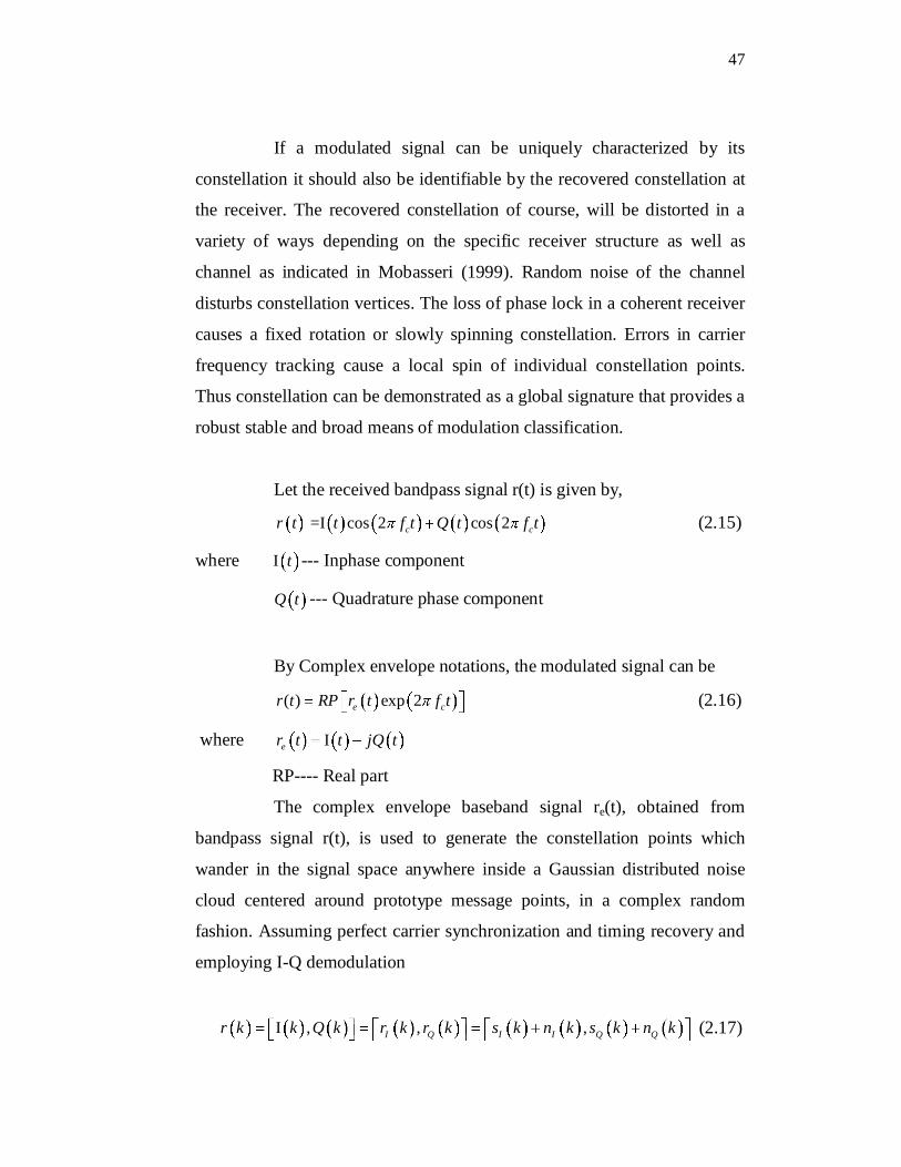
Let the received bandpass signal r(t) is given by,
=I cos 2 cos 2c cr t t f t Q t f t (2.15)
where I t --- Inphase component
Q t --- Quadrature phase component
By Complex envelope notations, the modulated signal can be
( ) exp 2e cr t RP r t f t (2.16)
where Ier t t jQ t
RP---- Real part
The complex envelope baseband signal re(t), obtained from
bandpass signal r(t), is used to generate the constellation points which
wander in the signal space anywhere inside a Gaussian distributed noise
cloud centered around prototype message points, in a complex random
fashion. Assuming perfect carrier synchronization and timing recovery and
employing I-Q demodulation
I , , ,I Q I I Q Qr k k Q k r k r k s k n k s k n k (2.17)
48
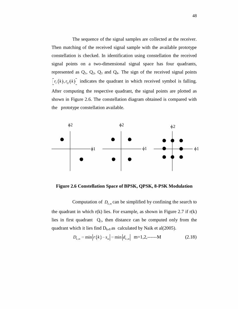
The sequence of the signal samples are collected at the receiver.
Then matching of the received signal sample with the available prototype
constellation is checked. In identification using constellation the received
signal points on a two-dimensional signal space has four quadrants,
represented as Q1, Q2, Q3 and Q4. The sign of the received signal points
,I Qr k r k indicates the quadrant in which received symbol is falling.
After computing the respective quadrant, the signal points are plotted as
shown in Figure 2.6. The constellation diagram obtained is compared with
the prototype constellation available.
Figure 2.6 Constellation Space of BPSK, QPSK, 8-PSK Modulation
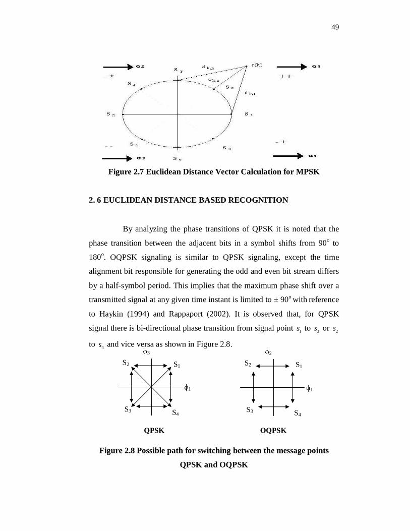
Computation of ,k mD can be simplified by confining the search to
the quadrant in which r(k) lies. For example, as shown in Figure 2.7 if r(k)
lies in first quadrant Q1, then distance can be computed only from the
quadrant which it lies find Dk,8 as calculated by Naik et al(2005).
, ,min mink m m k mD r k s d m=1,2,------M (2.18)
2 2 2
1 1 1
49
Figure 2.7 Euclidean Distance Vector Calculation for MPSK
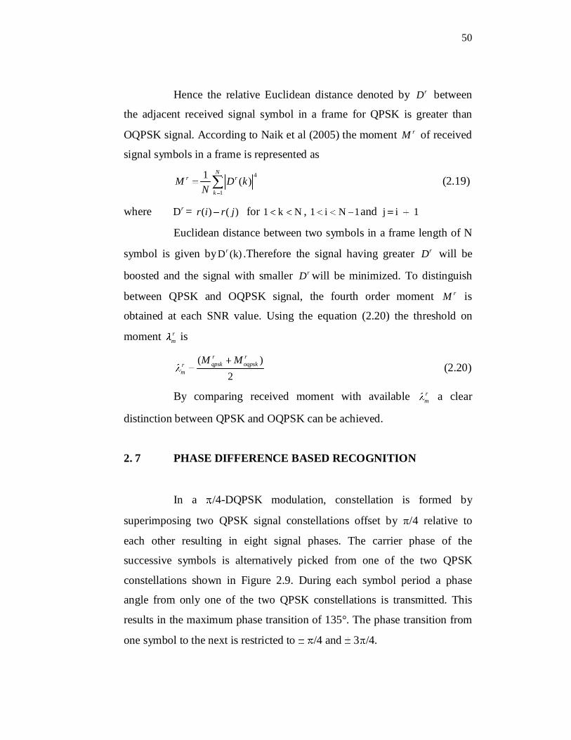
2. 6 EUCLIDEAN DISTANCE BASED RECOGNITION By analyzing the phase transitions of QPSK it is noted that the
phase transition between the adjacent bits in a symbol shifts from 90o to
180o. OQPSK signaling is similar to QPSK signaling, except the time
alignment bit responsible for generating the odd and even bit stream differs
by a half-symbol period. This implies that the maximum phase shift over a
transmitted signal at any given time instant is limited to ± 90o with reference
to Haykin (1994) and Rappaport (2002). It is observed that, for QPSK
signal there is bi-directional phase transition from signal point 1s to 3s or 2s
to 4s and vice versa as shown in Figure 2.8.
Figure 2.8 Possible path for switching between the message points
QPSK and OQPSK
S2 S1
S3 S4
1
3
QPSK
S2 S1
S3 S4
1
2
OQPSK
50
Hence the relative Euclidean distance denoted by rD between
the adjacent received signal symbol in a frame for QPSK is greater than
OQPSK signal. According to Naik et al (2005) the moment rM of received
signal symbols in a frame is represented as
4
1
1 ( )N
r r
k
M D kN
(2.19)
where Dr = ( ) ( )r i r j for 1 k N , 1 i N 1and j i 1
Euclidean distance between two symbols in a frame length of N
symbol is given byD (k)r .Therefore the signal having greater rD will be
boosted and the signal with smaller rD will be minimized. To distinguish
between QPSK and OQPSK signal, the fourth order moment rM is
obtained at each SNR value. Using the equation (2.20) the threshold on
moment rm is
( )2
r rqpsk oqpskr
m
M M (2.20)
By comparing received moment with available rm a clear
distinction between QPSK and OQPSK can be achieved.
2. 7 PHASE DIFFERENCE BASED RECOGNITION
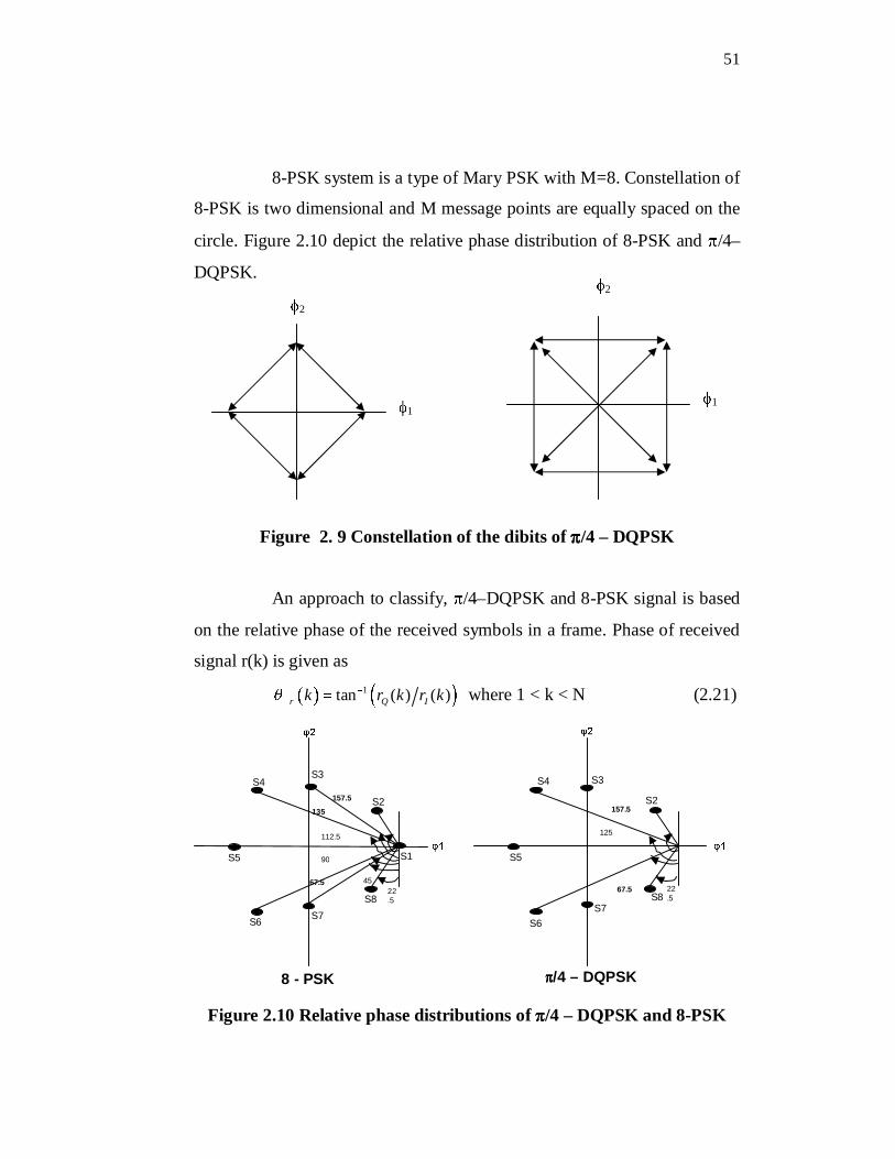
In a /4-DQPSK modulation, constellation is formed by
superimposing two QPSK signal constellations offset by /4 relative to
each other resulting in eight signal phases. The carrier phase of the
successive symbols is alternatively picked from one of the two QPSK
constellations shown in Figure 2.9. During each symbol period a phase
angle from only one of the two QPSK constellations is transmitted. This
results in the maximum phase transition of 135°. The phase transition from
one symbol to the next is restricted to /4 and 3 /4.
51
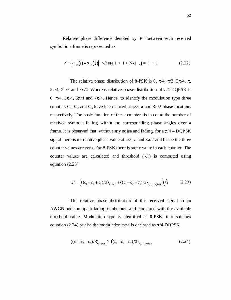
8-PSK system is a type of Mary PSK with M=8. Constellation of
8-PSK is two dimensional and M message points are equally spaced on the
circle. Figure 2.10 depict the relative phase distribution of 8-PSK and /4–
DQPSK.
Figure 2. 9 Constellation of the dibits of /4 – DQPSK
An approach to classify, /4–DQPSK and 8-PSK signal is based
on the relative phase of the received symbols in a frame. Phase of received
signal r(k) is given as1 tan ( ) ( )r Q Ik r k r k where 1 < k < N (2.21)
Figure 2.10 Relative phase distributions of /4 – DQPSK and 8-PSK
8 - PSK
67.5 45 22.5
90
112.5
135
157.5
S1
S6
S2
S4
S5
S7 S8
S3
/4 – DQPSK
S3
S2
S4
S5
S6 S7
S8
157.5
125
67.5 22.5
2
1
2
1
52
Relative phase difference denoted by rP between each received
symbol in a frame is represented as
P rr ri j where 1 < i < N-1 , j = i + 1 (2.22)
The relative phase distribution of 8-PSK is 0, /4, /2, 3 /4, ,
5 /4, 3 /2 and 7 /4. Whereas relative phase distribution of /4-DQPSK is
0, /4, 3 /4, 5 /4 and 7 /4. Hence, to identify the modulation type three
counters C1, C2 and C3 have been placed at /2, and 3 /2 phase locations
respectively. The basic function of these counters is to count the number of
received symbols falling within the corresponding phase angles over a
frame. It is observed that, without any noise and fading, for a /4 – DQPSK
signal there is no relative phase value at /2, and 3 /2 and hence the three
counter values are zero. For 8-PSK there is some value in each counter. The
counter values are calculated and threshold ( a ) is computed using
equation (2.23)
41 2 3 1 2 38( ) 3 ( ) 3 2a
PSK DQPSKc c c c c c (2.23)
The relative phase distribution of the received signal in an
AWGN and multipath fading is obtained and compared with the available
threshold value. Modulation type is identified as 8-PSK, if it satisfies
equation (2.24) or else the modulation type is declared as /4-DQPSK.
1 2 3 8( ) 3
PSKc c c >
41 2 3( ) 3DQPSK
c c c (2.24)
53
2. 8 RESULTS AND DISCUSSION
This section presents simulation results on the performance of
the proposed method executed in MATLAB. The simulation conditions are
shown in Table 2.2.
Table 2.2 Simulation conditions
Modulation Types BPSK, QPSK, OQPSK, 8-PSK, /4-DQPSK
Recognition MethodConstellation shape based analysis Euclidean distance analysisAdjacent bit Phase difference analysis
Channel TypeAWGN Rayleigh Fading No noise
SNR(db) 0 to 30
Number of samples 100 to 5000 bits
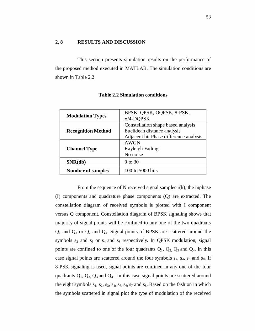
From the sequence of N received signal samples r(k), the inphase
(I) components and quadrature phase components (Q) are extracted. The
constellation diagram of received symbols is plotted with I component
versus Q component. Constellation diagram of BPSK signaling shows that
majority of signal points will be confined to any one of the two quadrants
Q1 and Q3 or Q2 and Q4. Signal points of BPSK are scattered around the
symbols s2 and s6 or s4 and s8 respectively. In QPSK modulation, signal
points are confined to one of the four quadrants Q1, Q2, Q3 and Q4. In this
case signal points are scattered around the four symbols s2, s4, s6 and s8. If
8-PSK signaling is used, signal points are confined in any one of the four
quadrants Q1, Q2, Q3 and Q4. In this case signal points are scattered around
the eight symbols s1, s2, s3, s4, s5, s6, s7 and s8. Based on the fashion in which
the symbols scattered in signal plot the type of modulation of the received
54
signal can be identified. The simulation results are shown in Figure 2.11
under AWGN and multipath fad conditions for varying SNR values.
Figure 2.11 Constellation based recognition of BPSK, QPSK and
8-PSK at SNR 5dB AWGN and fad
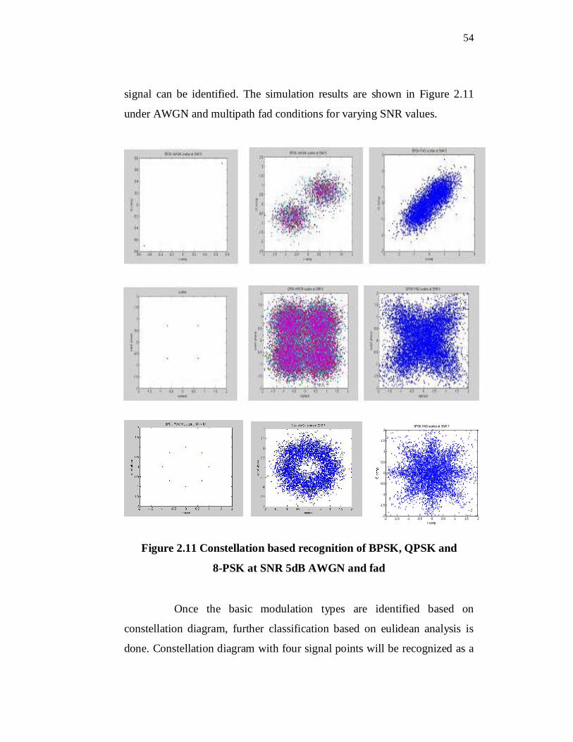
Once the basic modulation types are identified based on
constellation diagram, further classification based on eulidean analysis is
done. Constellation diagram with four signal points will be recognized as a
-2 -1.5 -1 -0.5 0 0.5 1 1.5 2-2
-1.5
-1
-0.5
0
0.5
1
1.5
2
I comp
8PSK FAD scatter at SNR 7
55
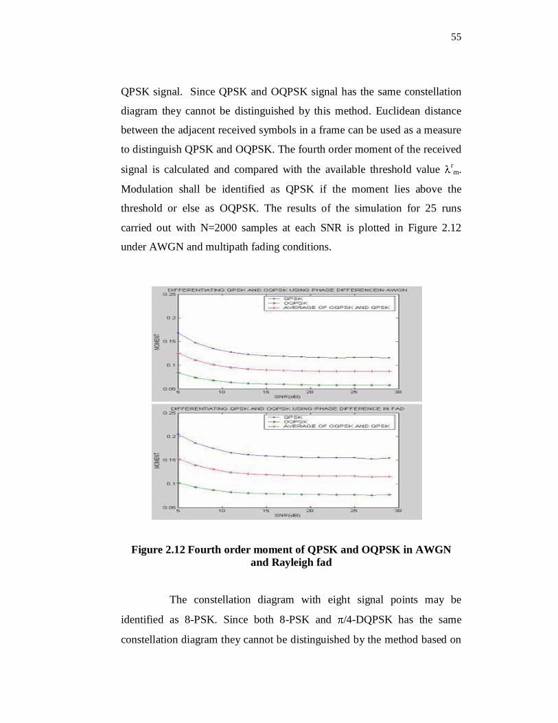
QPSK signal. Since QPSK and OQPSK signal has the same constellation
diagram they cannot be distinguished by this method. Euclidean distance
between the adjacent received symbols in a frame can be used as a measure
to distinguish QPSK and OQPSK. The fourth order moment of the received
signal is calculated and compared with the available threshold value rm.
Modulation shall be identified as QPSK if the moment lies above the
threshold or else as OQPSK. The results of the simulation for 25 runs
carried out with N=2000 samples at each SNR is plotted in Figure 2.12
under AWGN and multipath fading conditions.
Figure 2.12 Fourth order moment of QPSK and OQPSK in AWGNand Rayleigh fad
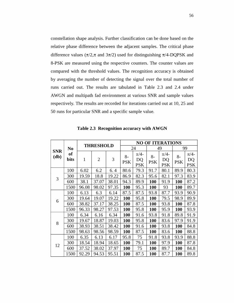
The constellation diagram with eight signal points may be
identified as 8-PSK. Since both 8-PSK and /4-DQPSK has the same
constellation diagram they cannot be distinguished by the method based on
56
constellation shape analysis. Further classification can be done based on the
relative phase difference between the adjacent samples. The critical phase
difference values ( /2, and 3 /2) used for distinguishing /4-DQPSK and
8-PSK are measured using the respective counters. The counter values are
compared with the threshold values. The recognition accuracy is obtained
by averaging the number of detecting the signal over the total number of
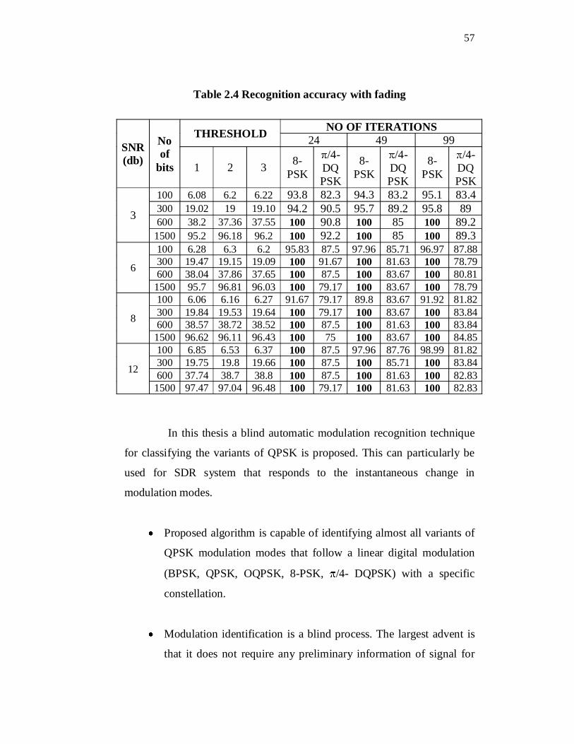
runs carried out. The results are tabulated in Table 2.3 and 2.4 under
AWGN and multipath fad environment at various SNR and sample values
respectively. The results are recorded for iterations carried out at 10, 25 and
50 runs for particular SNR and a specific sample value.
Table 2.3 Recognition accuracy with AWGN
SNR(db)
No of
bits
THRESHOLD NO OF ITERATIONS 24 49 99
1 2 3 8-PSK
/4- DQPSK
8-PSK
/4-DQPSK
8-PSK
/4-DQ PSK
3
100 6.02 6.2 6. 4 80.6 79.3 91.7 80.1 89.9 80.3300 19.59 18.8 19.22 86.9 82.3 95.6 82.1 97.3 83.9600 38.1 37.07 38.01 94.3 89.9 100 91.9 100 87.21500 96.08 98.02 97.35 100 95.3 100 93 100 89.7
6
100 6.13 6.3 6.14 87.5 87.5 93.8 87.7 93.9 90.9300 19.64 19.07 19.22 100 95.8 100 79.5 98.9 89.9600 38.82 37.17 38.25 100 87.5 100 93.8 100 87.81500 96.33 98.27 97.53 100 95.8 100 95.9 100 93.9
8
100 6.34 6.16 6.34 100 91.6 93.8 91.8 89.8 91.9300 19.67 18.87 19.03 100 95.8 100 83.6 97.9 91.9600 38.93 38.51 38.42 100 91.6 100 93.8 100 84.81500 98.63 98.56 98.59 100 87.5 100 83.6 100 88.8
12
100 6.35 6.13 6.17 95.8 75 91.8 93.8 93.9 88.8300 18.54 18.94 18.65 100 79.1 100 97.9 100 87.8600 37.52 38.02 37.97 100 75 100 89.7 100 84.81500 92.29 94.53 95.51 100 87.5 100 87.7 100 89.8
57
Table 2.4 Recognition accuracy with fading
SNR (db)
No of
bits
THRESHOLD NO OF ITERATIONS 24 49 99
1 2 3 8-PSK
/4-DQPSK
8-PSK
/4-DQ PSK
8-PSK
/4-DQPSK
3
100 6.08 6.2 6.22 93.8 82.3 94.3 83.2 95.1 83.4300 19.02 19 19.10 94.2 90.5 95.7 89.2 95.8 89600 38.2 37.36 37.55 100 90.8 100 85 100 89.2
1500 95.2 96.18 96.2 100 92.2 100 85 100 89.3
6
100 6.28 6.3 6.2 95.83 87.5 97.96 85.71 96.97 87.88300 19.47 19.15 19.09 100 91.67 100 81.63 100 78.79600 38.04 37.86 37.65 100 87.5 100 83.67 100 80.81
1500 95.7 96.81 96.03 100 79.17 100 83.67 100 78.79
8
100 6.06 6.16 6.27 91.67 79.17 89.8 83.67 91.92 81.82300 19.84 19.53 19.64 100 79.17 100 83.67 100 83.84600 38.57 38.72 38.52 100 87.5 100 81.63 100 83.84
1500 96.62 96.11 96.43 100 75 100 83.67 100 84.85
12
100 6.85 6.53 6.37 100 87.5 97.96 87.76 98.99 81.82300 19.75 19.8 19.66 100 87.5 100 85.71 100 83.84600 37.74 38.7 38.8 100 87.5 100 81.63 100 82.83
1500 97.47 97.04 96.48 100 79.17 100 81.63 100 82.83
In this thesis a blind automatic modulation recognition technique
for classifying the variants of QPSK is proposed. This can particularly be
used for SDR system that responds to the instantaneous change in
modulation modes.
Proposed algorithm is capable of identifying almost all variants of
QPSK modulation modes that follow a linear digital modulation
(BPSK, QPSK, OQPSK, 8-PSK, /4- DQPSK) with a specific
constellation.
Modulation identification is a blind process. The largest advent is
that it does not require any preliminary information of signal for
58
automatic estimation. Hence the available bandwidth for
transmission of information signal is increased.
It uses a deterministic method to speed up the identification
process. This is required, when algorithm is adapted to the adaptive
communication systems. The deterministic method identifies the
branch of tree-structured algorithm from properties of received
signal. (The computation time of signal analysis can be mitigated
dramatically.)
The proposed algorithm overcomes some of the disadvantages of
the existing algorithms which are SNR dependent and has shown
better result.
Certain assumptions like perfect carrier recovery, and
synchronization are made for the extraction of constellation points
from the received signal. Hence no pre-processing of received
samples is done.
The basic recognition is done based on the shape of constellation
diagram. QPSK variants with 2, 4 and 8 signal points are identified as
BPSK, QPSK and 8-PSK respectively. The results show that at high SNR
identification of symbol points clouded over constellation at particular
points. But for low SNR the shape of constellation diagram can be
improved by increasing the number of samples. The proposed algorithm is
able to identify the basic modulation at a low SNR of 3dB with 5,000
samples. Variant of OQPSK and QPSK is identified based on Euclidean
distance calculation between the adjacent bits. This method of classification
is able to recognize the signal with 100% efficiency at SNR
59
AWGN and for multipath fad signal with number of samples N=2000 for 8-
PSK. /4-DQPSK and 8-PSK can be differentiated based on relative phase
difference between adjacent bits. The algorithm can identify 8-PSK under
almost all conditions and /4-DQPSK can be identified at low SNR of 3dB
with 100% accuracy. Thus conclusion can be made that these computation
methods shows good results even in lower SNR (upto 3dB).