Embed Size (px)
Citation preview
Chapter 2Physical & Data-Link Layers
Professor Rick HanUniversity of Colorado at Boulder

Prof. Rick Han, University of Colorado at Boulder
Announcements
• Textbooks: Computer Networks, by Peterson and Davie• CU book store’s order has arrived• Read Chapter 1, start Chapter 2, sections 2.1-
2.8, skip Section 2.9 Network Adaptors
• Larger classroom – maybe…• Lectures will be online a few days after
each class• Follow the Lectures link on class Web site
• Homework #1 will be handed out next class
• Next, Chapter 2
Prof. Rick Han, University of Colorado at Boulder
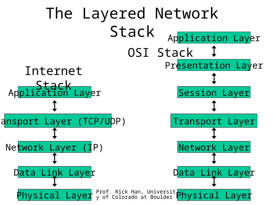
The Layered Network Stack
Physical Layer
Application Layer
Transport Layer (TCP/UDP)
Network Layer (IP)
Data Link Layer
Internet Stack
Physical Layer
Session Layer
Transport Layer
Network Layer
Data Link Layer
OSI StackPresentation Layer
Application Layer
Prof. Rick Han, University of Colorado at Boulder
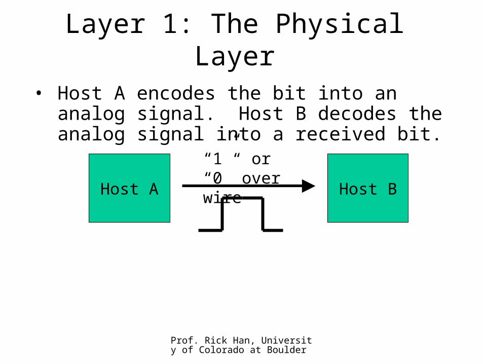
Layer 1: The Physical Layer
• Host A encodes the bit into an analog signal. Host B decodes the analog signal into a received bit.
Host A Host B
“1” or “0” over wire
Prof. Rick Han, University of Colorado at Boulder
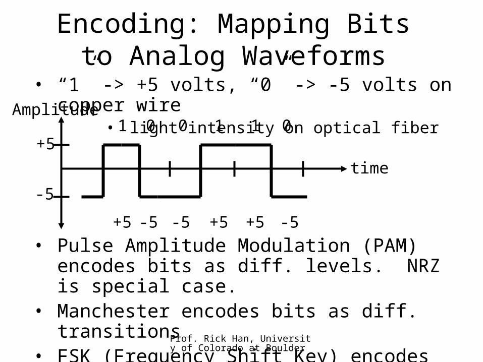
Encoding: Mapping Bits to Analog Waveforms
• “1” -> +5 volts, “0” -> -5 volts on copper wire
• light intensity on optical fiber
• Pulse Amplitude Modulation (PAM) encodes bits as diff. levels. NRZ is special case.
• Manchester encodes bits as diff. transitions
• FSK (Frequency Shift Key) encodes bits as diff. frequencies. 1200 bps modems.
Amplitude1 0 0 1 1
time
+5
-5
+5 -5 -5 +5 +5
0
-5
Prof. Rick Han, University of Colorado at Boulder
Sending More Bits Per Second
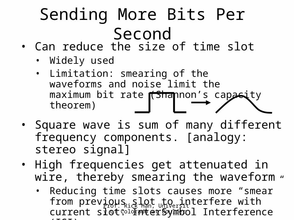
• Square wave is sum of many different frequency components. [analogy: stereo signal]
• High frequencies get attenuated in wire, thereby smearing the waveform• Reducing time slots causes more “smear” from
previous slot to interfere with current slot: InterSymbol Interference (ISI)
• Can reduce the size of time slot• Widely used• Limitation: smearing of the waveforms and
noise limit the maximum bit rate (Shannon’s capacity theorem)
Prof. Rick Han, University of Colorado at Boulder
Sending More Bits Per Second (2)
111
110
101
100
011
010
001
000
+7 V
+5
+3
+1
-1
-3
-5
-7
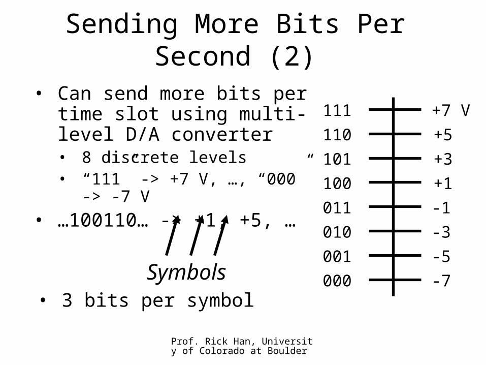
• Can send more bits per time slot using multi-level D/A converter• 8 discrete levels• “111” -> +7 V, …, “000” ->
-7 V
• …100110… -> +1, +5, …
• 3 bits per symbolSymbols
Prof. Rick Han, University of Colorado at Boulder
Sending More Bits Per Second (3)
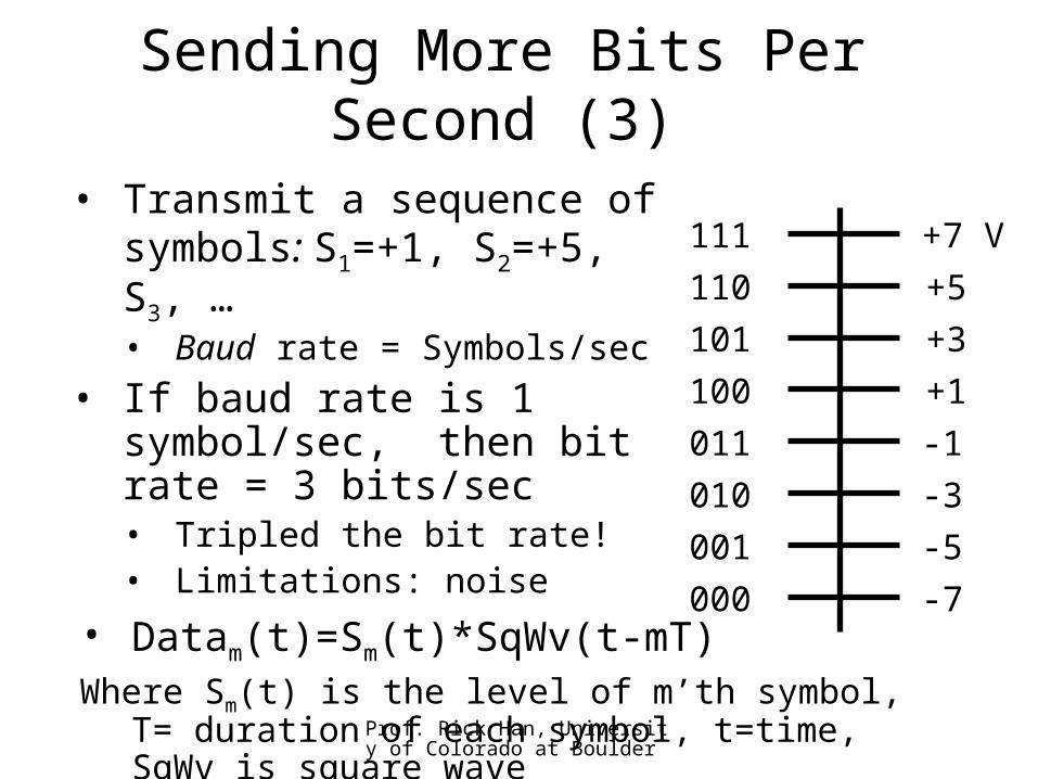
• Transmit a sequence of symbols: S1=+1, S2=+5, S3, …• Baud rate = Symbols/sec
• If baud rate is 1 symbol/sec, then bit rate = 3 bits/sec• Tripled the bit rate!• Limitations: noise
111
110
101
100
011
010
001
000
+7 V
+5
+3
+1
-1
-3
-5
-7• Datam(t)=Sm(t)*SqWv(t-mT)Where Sm(t) is the level of m’th symbol, T=
duration of each symbol, t=time, SqWv is square wave
Prof. Rick Han, University of Colorado at Boulder
Sending More Bits Per Second (4)
• Can send more bits over different frequencies, [analogy: AM/FM]• Modulate Sm(t) up to 3000 Hz, demodulate
down• Datam(t) = Sm(t)*cos(2t) + S’m(t)*cos
(2t) [simplified: sq wave not shown]
• Can send more bits over the same frequency!• Datam(t) = Sm(t)*cos(2t) + S’m(t)*sin
(2t)• This is called Quadrature Amplitude
Modulation (QAM). • If Sm(t), and S’m(t) both have 4 levels, then
this is called 16-QAM. 9600 bps modems use this. Baud?
Prof. Rick Han, University of Colorado at Boulder
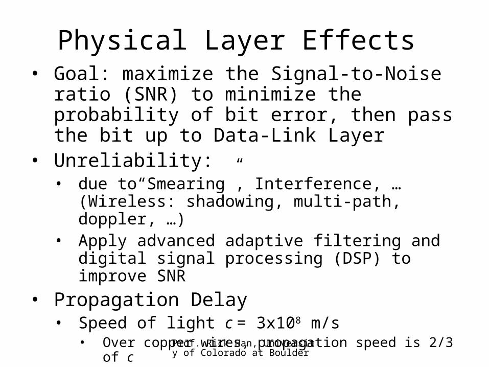
Physical Layer Effects• Goal: maximize the Signal-to-Noise ratio
(SNR) to minimize the probability of bit error, then pass the bit up to Data-Link Layer
• Unreliability:• due to“Smearing”, Interference, … (Wireless:
shadowing, multi-path, doppler, …)• Apply advanced adaptive filtering and digital
signal processing (DSP) to improve SNR
• Propagation Delay• Speed of light c = 3x10⁸ m/s
• Over copper wires, propagation speed is 2/3 of c
• Satellite links have long prop. delays (~120 ms one-way)
• Interactivity requires <400 ms roundtrip
Prof. Rick Han, University of Colorado at Boulder
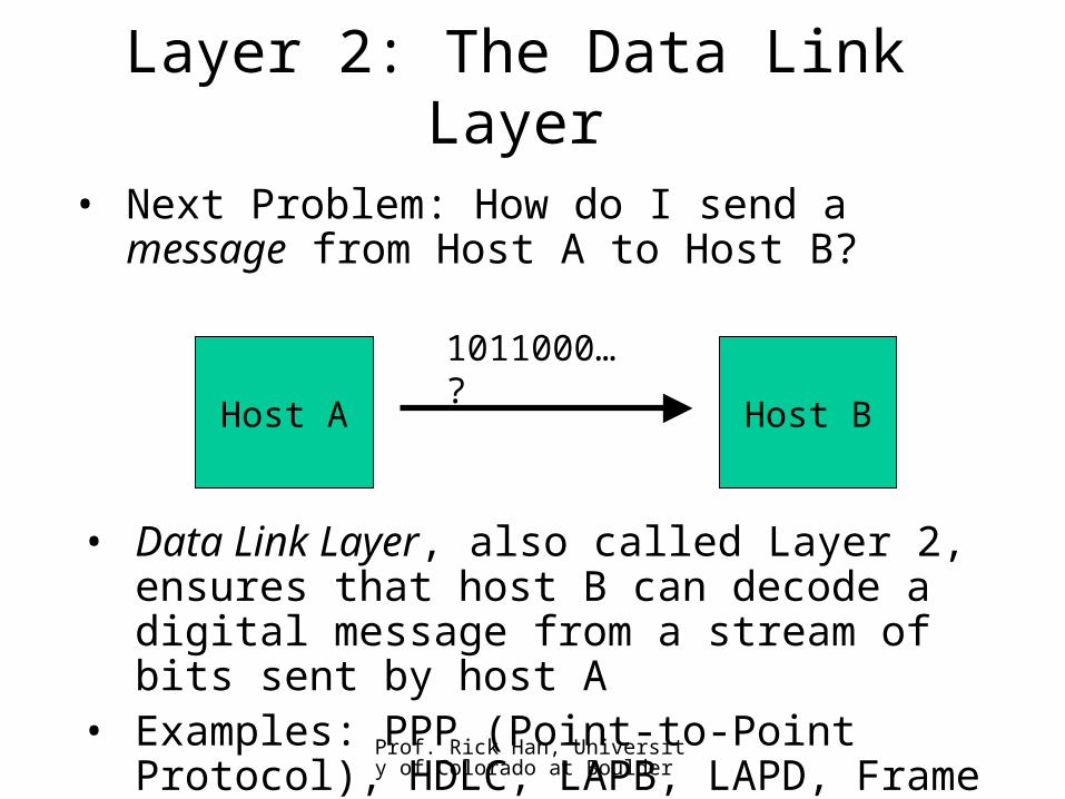
Layer 2: The Data Link Layer
• Next Problem: How do I send a message from Host A to Host B?
• Data Link Layer, also called Layer 2, ensures that host B can decode a digital message from a stream of bits sent by host A
• Examples: PPP (Point-to-Point Protocol), HDLC, LAPB, LAPD, Frame Relay, …
Host A Host B
1011000…?
Prof. Rick Han, University of Colorado at Boulder
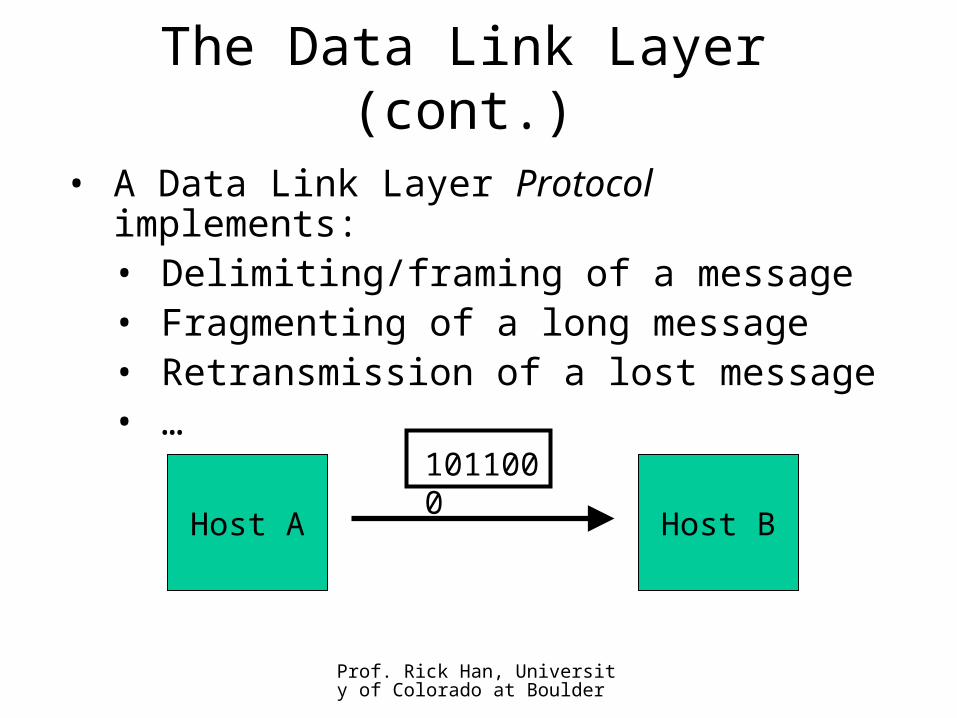
The Data Link Layer (cont.)
• A Data Link Layer Protocol implements:• Delimiting/framing of a message• Fragmenting of a long message• Retransmission of a lost message• …
Host A Host B
1011000
Prof. Rick Han, University of Colorado at Boulder
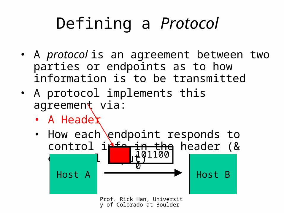
Defining a Protocol
• A protocol is an agreement between two parties or endpoints as to how information is to be transmitted
• A protocol implements this agreement via:• A Header• How each endpoint responds to control
info in the header (& external input)
Host A Host B
1011000
Prof. Rick Han, University of Colorado at Boulder
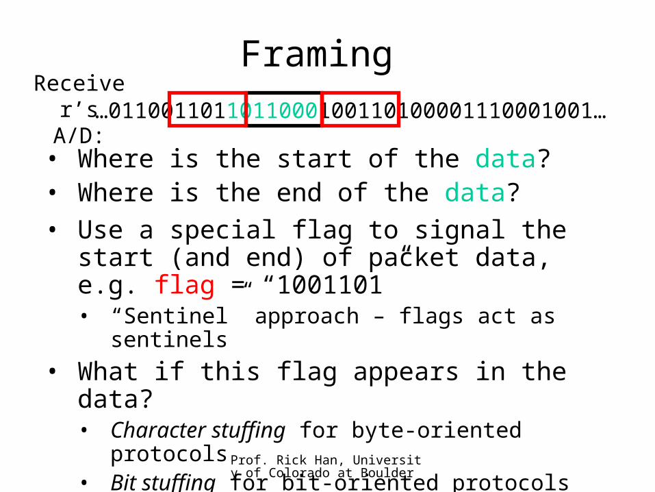
Framing
• Where is the start of the data?• Where is the end of the data?
…0110011011011000100110100001110001001…
• Use a special flag to signal the start (and end) of packet data, e.g. flag = “1001101”• “Sentinel” approach – flags act as sentinels
• What if this flag appears in the data?• Character stuffing for byte-oriented
protocols• Bit stuffing for bit-oriented protocols
Receiver’s A/D:
Prof. Rick Han, University of Colorado at Boulder
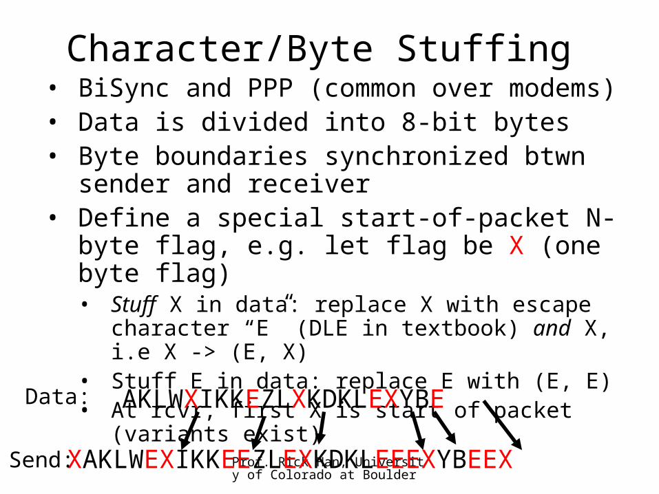
Character/Byte Stuffing• BiSync and PPP (common over modems)• Data is divided into 8-bit bytes• Byte boundaries synchronized btwn sender
and receiver• Define a special start-of-packet N-byte
flag, e.g. let flag be X (one byte flag)• Stuff X in data: replace X with escape
character “E” (DLE in textbook) and X, i.e X -> (E, X)
• Stuff E in data: replace E with (E, E)• At rcvr, first X is start of packet (variants exist)
AKLWXIKKEZLXKDKLEXYBEData:
XAKLWEXIKKEEZLEXKDKLEEEXYBEEXSend:
Prof. Rick Han, University of Colorado at Boulder
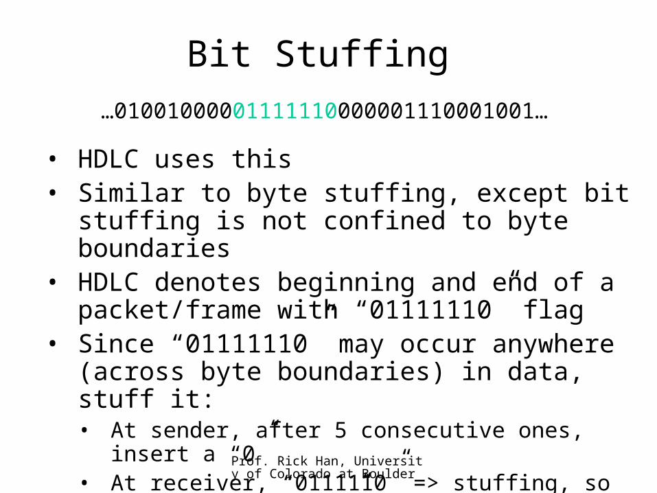
Bit Stuffing
• HDLC uses this• Similar to byte stuffing, except bit stuffing
is not confined to byte boundaries• HDLC denotes beginning and end of a
packet/frame with “01111110” flag• Since “01111110” may occur anywhere
(across byte boundaries) in data, stuff it:• At sender, after 5 consecutive ones, insert a
“0”• At receiver, “0111110” => stuffing, so destuff,
“01111110” => end of frame, “01111111” => error
…01001000001111110000001110001001…
Prof. Rick Han, University of Colorado at Boulder
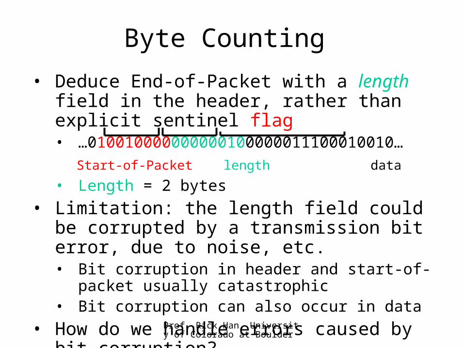
Byte Counting
• Deduce End-of-Packet with a length field in the header, rather than explicit sentinel flag• …010010000000000100000011100010010…
Start-of-Packet length data
• Length = 2 bytes
• Limitation: the length field could be corrupted by a transmission bit error, due to noise, etc.• Bit corruption in header and start-of-packet
usually catastrophic• Bit corruption can also occur in data
• How do we handle errors caused by bit corruption?
Prof. Rick Han, University of Colorado at Boulder
Error Detection
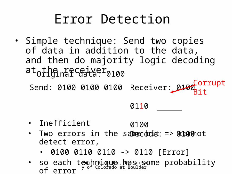
• Simple technique: Send two copies of data in addition to the data, and then do majority logic decoding at the receiver
• Inefficient• Two errors in the same bit => cannot detect
error,• 0100 0110 0110 -> 0110 [Error]
• so each technique has some probability of error
Original data: 0100
Send: 0100 0100 0100 Receiver: 0100 0110 0100Decode: 0100
CorruptBit
Prof. Rick Han, University of Colorado at Boulder
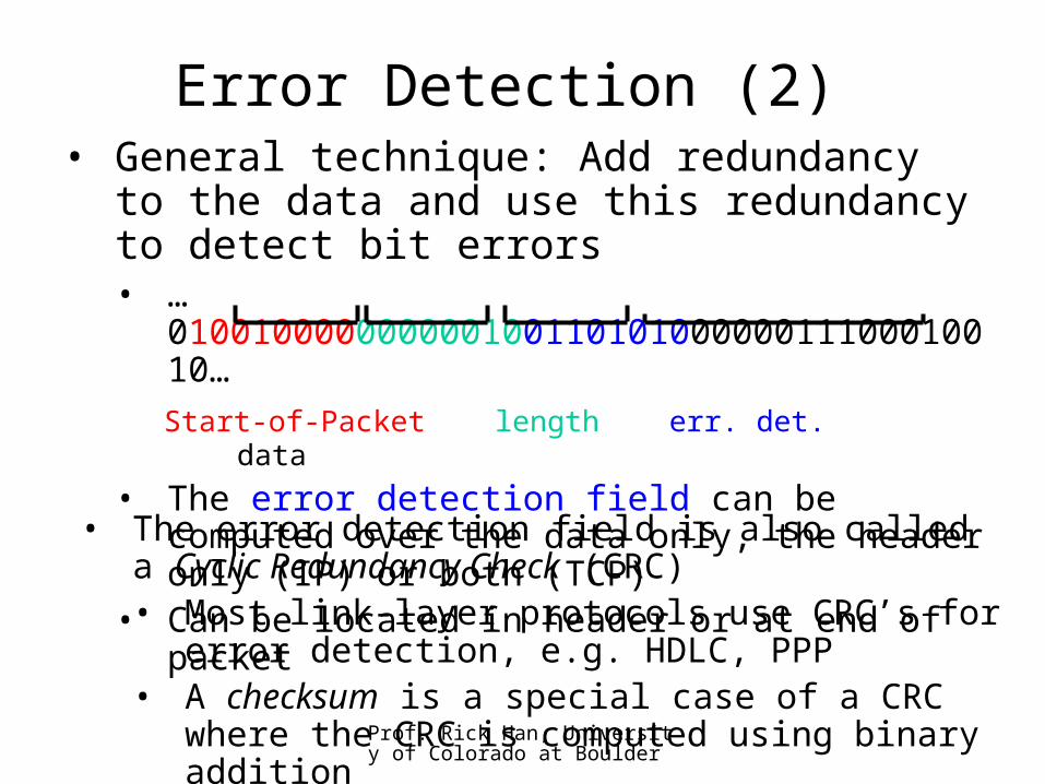
Error Detection (2)• General technique: Add redundancy to
the data and use this redundancy to detect bit errors• …01001000000000010011010100000011100010010…
Start-of-Packet length err. det. data
• The error detection field can be computed over the data only, the header only (IP) or both (TCP)
• Can be located in header or at end of packet• The error detection field is also called a Cyclic Redundancy Check (CRC)• Most link-layer protocols use CRC’s for error
detection, e.g. HDLC, PPP• A checksum is a special case of a CRC where
the CRC is computed using binary addition
Prof. Rick Han, University of Colorado at Boulder
Error Detection (3)• The Internet checksum:
• Divide your data into 16-bit segments• Add each of the 16-bit segments, using one’s
complement binary addition• One’s complement of the final sum is your 16-
bit IP checksum• Send IP checksum with the IP packet
• An alternative checksum: XOR instead of one’s complement
• Checksum’s are relatively weak compared to CRC’s but are easy to compute• A bit error twice in the same offset position
within the 16-bit segment will go undetected
Prof. Rick Han, University of Colorado at Boulder
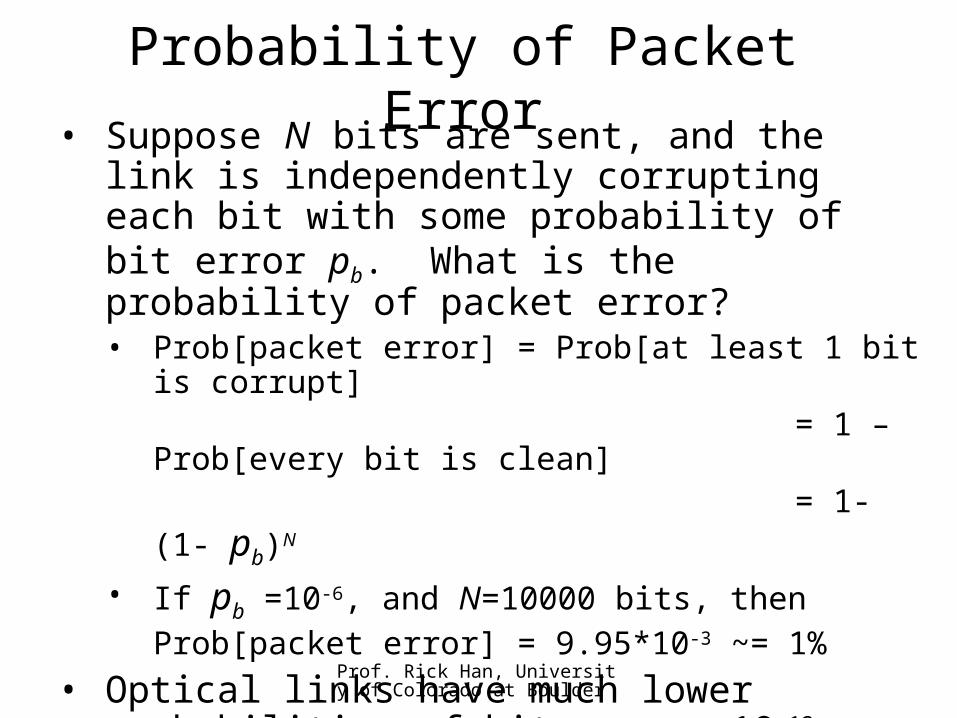
Probability of Packet Error• Suppose N bits are sent, and the link is
independently corrupting each bit with some probability of bit error pb. What is the probability of packet error?• Prob[packet error] = Prob[at least 1 bit is
corrupt] = 1 – Prob[every bit is
clean]
= 1-(1- pb)N
• If pb =10-6, and N=10000 bits, then Prob[packet error] = 9.95*10-3 ~= 1%
• Optical links have much lower probabilities of bit error: 10–12
• Wireless links have much higher probabilities of bit error: 10-3 in fades [send small packets]

Prof. Rick Han, University of Colorado at Boulder
Error Correction• Forward Error Correction (FEC):
• Rather than just detect a bit error, correct a bit error
• Add K bits of redundancy to N bits, to form a (N+K)-bit long packet, or vector
• N dimensions -> N+K dimensions• 2N patterns or vectors mapped into 2N+K
possibilities• Spread out these vectors as far away from
neighbors as possible in (N+K)-dimensional space• N=2, K=3, N+K=5• Receive 01111 - closest to 11111, so decode “11” and correct one bit error
00 0000001 1010110 0101011 11111