Embed Size (px)
Citation preview
2A-32 Chapter 2 Part A Engine, clutch and transmission (XV535 models)
16.5a Take off the pressure plate . . . 16.5b . . . together with the push piece (A)and short pushrod (B)
16.5c The friction plates and metal platescan be removed as a set
16.6a Pull out the steel ball witha magnet.. .
16.6b . . . then pull out the long pushrod 16.7a Bend back the lockwasher
16.7b You'll need a tool to keep the clutch hub from turning; thisis the Yamaha special t o o l . . .
1) Clutch boss nut 2) Holding tool
16.7c . . . or you can make your own tool from steel strap
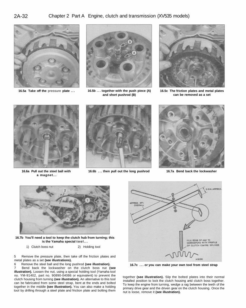
5 Remove the pressure plate, then take off the friction plates andmetal plates as a set (see illustrations).6 Remove the steel ball and the long pushrod (see illustration).7 Bend back the lockwasher on the clutch boss nut (seeillustration). Loosen the nut, using a special holding tool (Yamaha toolno. YM-91402, part no. 90890-04086 or equivalent) to prevent theclutch housing from turning (see illustration). An alternative to this toolcan be fabricated from some steel strap, bent at the ends and boltedtogether in the middle (see illustration). You can also make a holdingtool by drilling through a steel plate and friction plate and bolting them
together (see illustration). Slip the bolted plates into their normalinstalled position to lock the clutch housing artd clutch boss together.To keep the engine from turning, wedge a rag between the teeth of theprimary drive gear and the driven gear on the clutch housing. Once thenut is loose, remove it (see illustration).
Chapter 2 Part A Engine, clutch and transmission (XV535 models) 2A-33
16.7d A holding tool can also be made bybolting an old metal plate and friction
plate together
16.7e Remove the nut . . . 16.8 . . . and the lockwasher
16.9a Pull the clutch boss of f . . . 16.9b . . . and remove the holding plate 16.10a Bend back thelockwasher (arrow)...
16.10b . . . then wedge a rag between thedrive and driven gears to keep them from
turning and loosen the nut
16.11a Remove the lockwasher . . . 16.11b . . . the retaining plate . . .
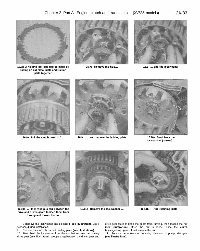
8 Remove the lockwasher and discard it (see illustration). Use anew one during installation.9 Remove the clutch boss and holding plate (see illustrations).10 Bend back the lockwasher from the nut that secures the primarydrive gear (see illustration). Wedge a rag between the driven gear and
drive gear teeth to keep the gears from turning, then loosen the nut(see illustration). Once the nut is loose, slide the clutchhousing/driven gear off and remove the nut.11 Remove the lockwasher, retaining plate and oil pump drive gear(see illustrations).
2A-34 Chapter 2 Part A Engine, clutch and transmission (XV535 models)
16.11c . . . the oil pump drive gear. . 16.12a . . . the primary drive gear . . . 16.12b . . . and the Woodruff key
16.13a Pull one end of the wire circlip outof its hole in the clutch boss . . .
16.13b . . . and work the circlip out ofits groove
16.13c Pull off the clutch damper plate . . .
16.13d .... the seat spring . . . 16.13e . . . and the seat plate 16.15 Measure the clutch springfree length
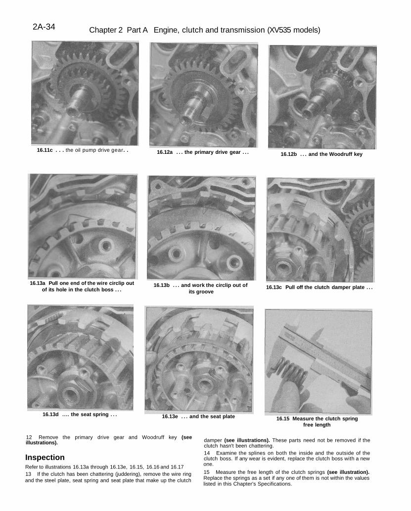
12 Remove the primary drive gear and Woodruff key (seeillustrations).
InspectionRefer to illustrations 16.13a through 16.13e, 16.15, 16.16 and 16.1713 If the clutch has been chattering (juddering), remove the wire ringand the steel plate, seat spring and seat plate that make up the clutch
damper (see illustrations). These parts need not be removed if theclutch hasn't been chattering.14 Examine the splines on both the inside and the outside of theclutch boss. If any wear is evident, replace the clutch boss with a newone.
15 Measure the free length of the clutch springs (see illustration).Replace the springs as a set if any one of them is not within the valueslisted in this Chapter's Specifications.
Chapter 2 Part A Engine, clutch and transmission (XV535 models) 2A-35
16.16 Measure the thickness of thefriction plates
16.17 Check the metal plates for warpage 16.28 With the nut tightened to thespecified torque, bend the lockwasher
against one of the flats
'6.29 Install the oil pump driven gear andsecure it with a new snap-ring
16.30 Install the clutch boss lockwasher 16.31 Once the nut is tightened to thespecified torque, bend the lockwasher
against the nut
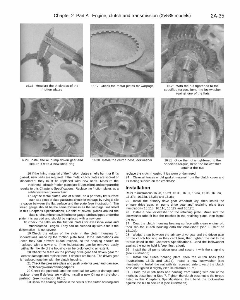
16 If the lining material of the friction plates smells burnt or if it'sglazed, new parts are required. If the metal clutch plates are scored ordiscolored, they must be replaced with new ones. Measure the
thickness of each friction plate (see illustration) and compare theresults to this,Chapter's Specifications. Replace the friction plates as a
set if any are near the wear limit.17 Lay the metal plates, one at a time, on a perfectly flat surfacesuch as a piece of plate glass) and check for warpage by trying to slip
a gauge between the flat surface and the plate (see illustration). Thefeeler gauge should be the same thickness as the warpage limit listedin this Chapter's Specifications. Do this at several places around the
plate's circumference. If the feeler gauge can be slipped under theplate, it is warped and should be replaced with a new one.
18 Check the tabs on the friction plates for excessive wear andmushroomed edges. They can be cleaned up with a file if the
deformation is not severe.19 Check the edges of the slots in the clutch housing for
indentations made by the friction plate tabs. If the indentations aredeep they can prevent clutch release, so the housing should bereplaced with a new one. If the indentations can be removed easilywith a file, the life of the housing can be prolonged to an extent.
20 Check the teeth on the primary drive gear and driven gear forwear or damage and replace them if defects are found. The driven gear
is replaced together with the clutch housing.21 Check the pressure plate and push plate for wear and damage.Replace any worn or damaged parts.22 Check the pushrods and the steel ball for wear or damage and
replace them if defects are visible. Install a new O-ring on the shortpushrod (see illustration 16.5b).
23 Check the bearing surface in the center of the clutch housing and
replace the clutch housing if it's worn or damaged.24 Clean all traces of old gasket material from the clutch cover andits mating surface on the crankcase.
InstallationRefer to illustrations 16.28, 16.29, 16.30, 16.31, 16.34, 16.35, 16.37a,16.37b, 16,38a, 16.38b and 16.38c25 Install the primary drive gear Woodruff key, then install theprimary drive gear, oil pump drive gear and" retaining plate (seeillustrations 16.11b, 16.11c, 16.12a and 16.12b).26 Install a new lockwasher on the retaining plate. Make sure thelockwasher tabs fit into the notches in the retaining plate, then installthe nut.,27 Coat the clutch housing bearing surface with clean engine oil,then slip the clutch housing onto the crankshaft (see illustration16.10a).28 Wedge a rag between the primary drive gear and the driven gearon the clutch housing so they can't turn, then tighten the nut to thetorque listed in this Chapter's Specifications. Bend the lockwasheragainst the nut to hold it (see illustration).29 Install the oil pump driven gear and secure it with the snap-ring(see illustration).30 Install the clutch holding plate, then the clutch boss (seeillustrations 16.9b and 16.9a). Install a new lockwasher (seeillustration). Install the nut with its recessed side toward the clutchboss and tighten it slightly (see illustration 16.7e).31 • Hold the clutch boss and housing from turning with one of themethods described in Step 7. Tighten the clutch boss nut to the torquelisted in this Chapter's Specifications, then bend the lockwasheragainst the nut to secure it (see illustration).
2A-36 Chapter 2 Part A Engine, clutch and transmission (XV535 models)
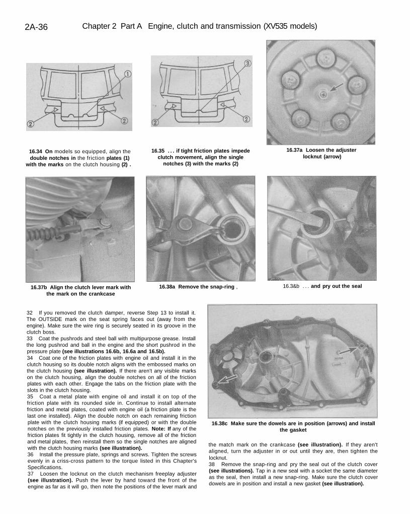
16.34 On models so equipped, align thedouble notches in the friction plates (1)
with the marks on the clutch housing (2) .
16.35 . . . if tight friction plates impedeclutch movement, align the single
notches (3) with the marks (2)
16.37a Loosen the adjusterlocknut (arrow)
16.37b Align the clutch lever mark withthe mark on the crankcase
16.38a Remove the snap-ring , 16.3&b . . . and pry out the seal
16.38c Make sure the dowels are in position (arrows) and installthe gasket
32 If you removed the clutch damper, reverse Step 13 to install it.The OUTSIDE mark on the seat spring faces out (away from theengine). Make sure the wire ring is securely seated in its groove in theclutch boss.33 Coat the pushrods and steel ball with multipurpose grease. Installthe long pushrod and ball in the engine and the short pushrod in thepressure plate (see illustrations 16.6b, 16.6a and 16.5b).34 Coat one of the friction plates with engine oil and install it in theclutch housing so its double notch aligns with the embossed marks onthe clutch housing (see illustration). If there aren't any visible markson the clutch housing, align the double notches on all of the frictionplates with each other. Engage the tabs on the friction plate with theslots in the clutch housing.35 Coat a metal plate with engine oil and install it on top of thefriction plate with its rounded side in. Continue to install alternatefriction and metal plates, coated with engine oil (a friction plate is thelast one installed). Align the double notch on each remaining frictionplate with the clutch housing marks (if equipped) or with the doublenotches on the previously installed friction plates. Note: If any of thefriction plates fit tightly in the clutch housing, remove all of the frictionand metal plates, then reinstall them so the single notches are alignedwith the clutch housing marks (see illustration).36 Install the pressure plate, springs and screws. Tighten the screwsevenly in a criss-cross pattern to the torque listed in this Chapter'sSpecifications.37 Loosen the locknut on the clutch mechanism freeplay adjuster(see illustration). Push the lever by hand toward the front of theengine as far as it will go, then note the positions of the lever mark and
the match mark on the crankcase (see illustration). If they aren'taligned, turn the adjuster in or out until they are, then tighten thelocknut.38 Remove the snap-ring and pry the seal out of the clutch cover(see illustrations). Tap in a new seal with a socket the same diameteras the seal, then install a new snap-ring. Make sure the clutch coverdowels are in position and install a new gasket (see illustration).
Chapter 2 Part A Engine, clutch and transmission (XV535 models) 2A-37
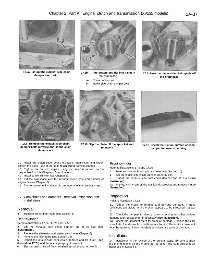
17.2a Lift out the exhaust side chaindamper (arrow)...
17.2b . . . the bottom end fits into a slot inthe crankcase
a) Chain damper slotb) Intake side chain damper bolts
17.5 Take the intake side chain guide offthe crankcase
17.9 Remove the exhaust side chaindamper bolts (arrows) and lift the chain
damper out
17.10 Slip the chain off the sprocket andremove it
17.12 Check the friction surface of eachdamper for wear or scoring
39 Install the clutch cover over the dowels, then install and finger-tighten the bolts. Four of the bolts retain wiring harness clamps.40 Tighten the bolts in stages, using a criss-criss pattern, to thetorque listed in this Chapter's Specifications.41 Install a new oil filter (see Chapter 1).42 Fill the crankcase with the recommended type and amount ofengine oil (see Chapter 1).43 The remainder of installation is the reverse of the removal steps.
17 Cam chains and dampers - removal, inspection andinstallation
Removal1 Remove the cylinder head (see Section 8).
Rear cylinderRefer to illustrations 17.2a, 17.2b and 17.52 Lift the exhaust side chain damper out of its slot (seeillustrations).3 Remove the alternator and starter clutch (see Chapter 8).4 Remove the idler gears (see Section 14).5 Unbolt the intake side cam chain damper and lift it out (seeillustration 17.2b) and the accompanying illustration).6 Slip the cam chain off the crankshaft sprocket and remove it.
Front cylinderRefer to illustrations 17.9 and 17.107 Remove the clutch and primary gears (see Section 16).8 Lift the intake side chain damper out of its slot.9 Unbolt the exhaust side cam chain damper and lift it out (seeillustration).10 Slip the cam chain off the crankshaft sprocket and remove it (seeillustration).
InspectionRefer to illustration 17.12
11 Check the chain for binding and obvious damage. If theseconditions are visible, or if the chain appears to be stretched, replaceit.12 Check the dampers for deep grooves, cracking and other obviousdamage and replace them if necessary (see illustration).13 Check the sprocket teeth for wear or damage. Replace the camsprockets if undesirable conditions are found. The entire crankshaftmust be replaced if the crankshaft sprockets are worn or damaged.
Installation14 Installation is the reverse of the removal steps. Be sure to alignthe timing marks on the crankshaft sprocket and cam sprocket asdescribed in Section 8.
2A-38 Chapter 2 Part A Engine, clutch and transmission (XV535 models)
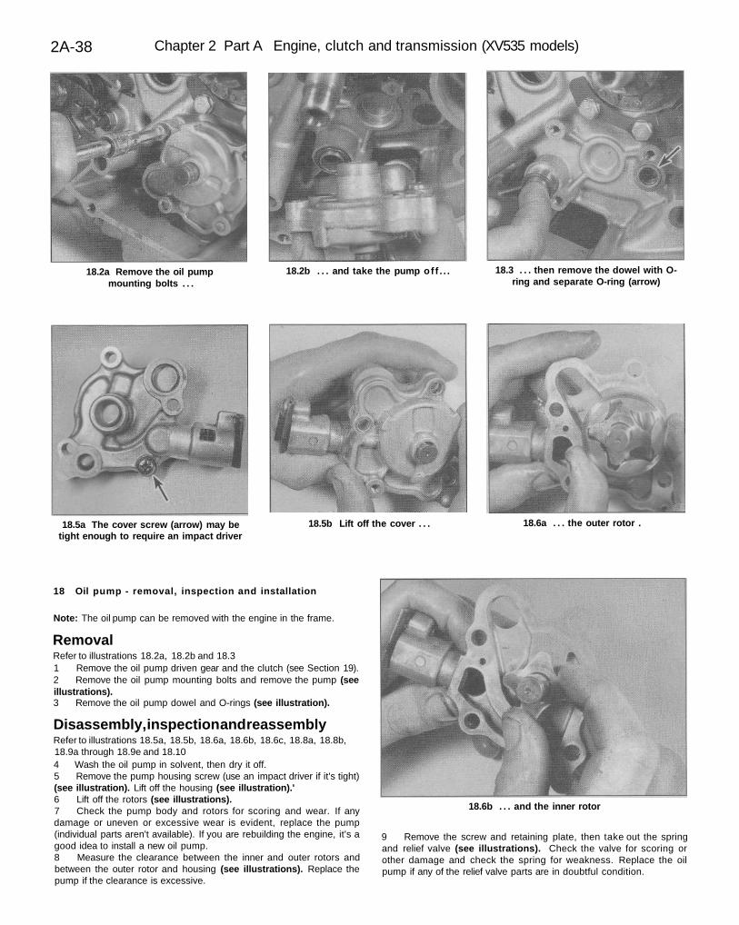
18.2a Remove the oil pumpmounting bolts . . .
18.2b . . . and take the pump of f . . . 18.3 . . . then remove the dowel with O-ring and separate O-ring (arrow)
18.5a The cover screw (arrow) may betight enough to require an impact driver
18.5b Lift off the cover . . . 18.6a . . . the outer rotor .
18.6b . . . and the inner rotor
18 Oil pump - removal, inspection and installation
Note: The oil pump can be removed with the engine in the frame.
RemovalRefer to illustrations 18.2a, 18.2b and 18.31 Remove the oil pump driven gear and the clutch (see Section 19).2 Remove the oil pump mounting bolts and remove the pump (seeillustrations).3 Remove the oil pump dowel and O-rings (see illustration).
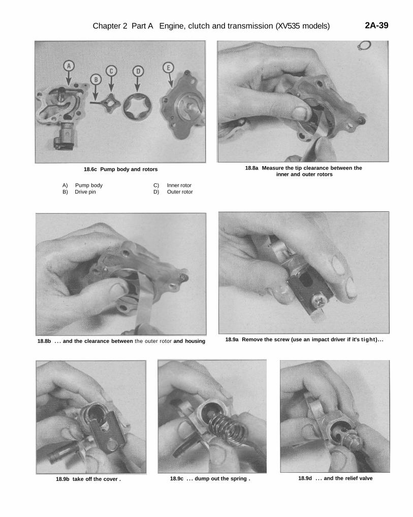
Disassembly, inspection and reassemblyRefer to illustrations 18.5a, 18.5b, 18.6a, 18.6b, 18.6c, 18.8a, 18.8b,18.9a through 18.9e and 18.104 Wash the oil pump in solvent, then dry it off.5 Remove the pump housing screw (use an impact driver if it's tight)(see illustration). Lift off the housing (see illustration).'6 Lift off the rotors (see illustrations).7 Check the pump body and rotors for scoring and wear. If anydamage or uneven or excessive wear is evident, replace the pump(individual parts aren't available). If you are rebuilding the engine, it's agood idea to install a new oil pump.8 Measure the clearance between the inner and outer rotors andbetween the outer rotor and housing (see illustrations). Replace thepump if the clearance is excessive.
9 Remove the screw and retaining plate, then take out the springand relief valve (see illustrations). Check the valve for scoring orother damage and check the spring for weakness. Replace the oilpump if any of the relief valve parts are in doubtful condition.
Chapter 2 Part A Engine, clutch and transmission (XV535 models) 2A-39
18.6c Pump body and rotors
A) Pump body C) Inner rotorB) Drive pin D) Outer rotor
18.8a Measure the tip clearance between theinner and outer rotors
18.8b . . . and the clearance between the outer rotor and housing 18.9a Remove the screw (use an impact driver if it's t ight) . . .
18.9b take off the cover . 18.9c . . . dump out the spring . 18.9d . . . and the relief valve
2A-40 Chapter 2 Part A Engine, clutch and transmission (XV535 models)
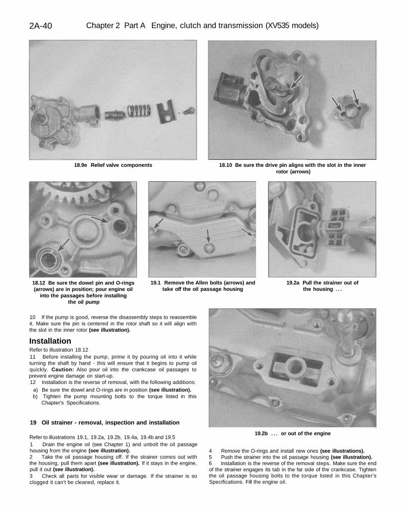
18.9e Relief valve components 18.10 Be sure the drive pin aligns with the slot in the innerrotor (arrows)
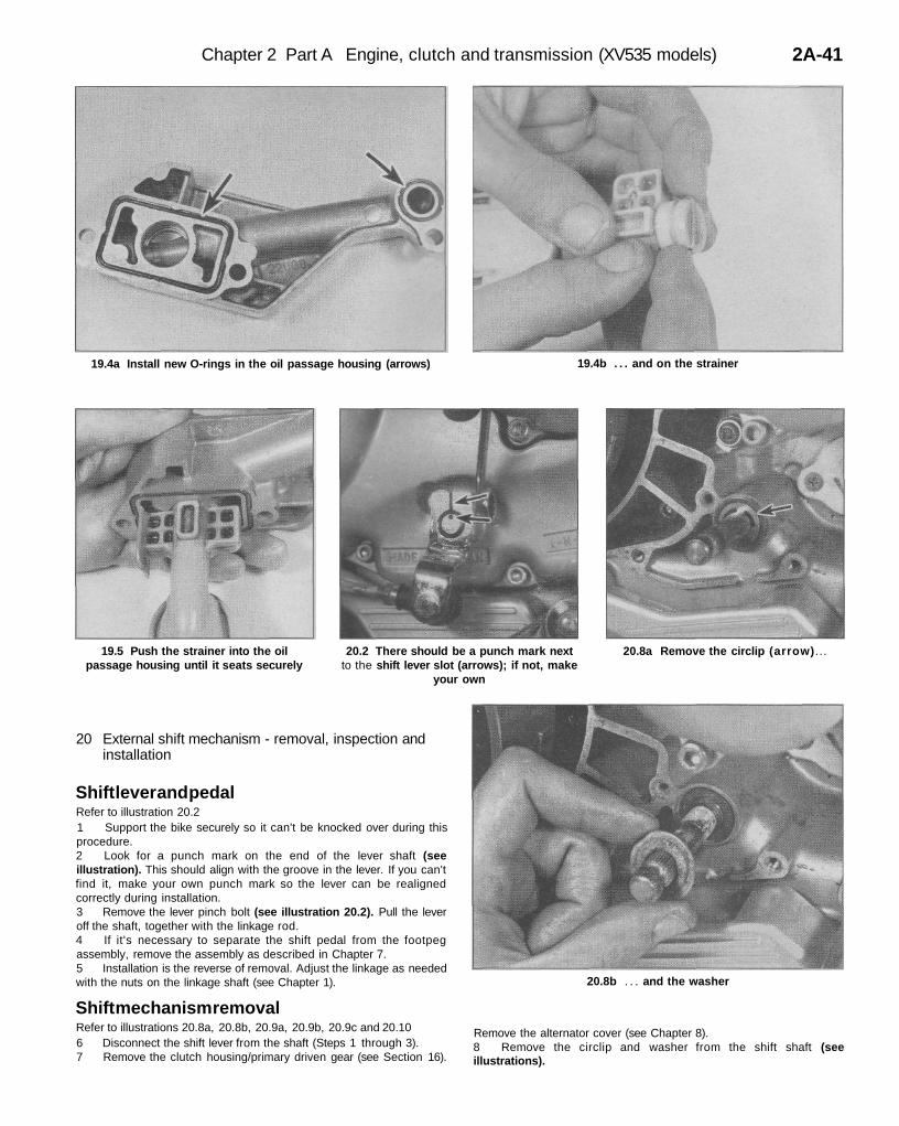
18.12 Be sure the dowel pin and O-rings(arrows) are in position; pour engine oil
into the passages before installingthe oil pump
19.1 Remove the Allen bolts (arrows) andtake off the oil passage housing
19.2a Pull the strainer out ofthe housing . . .
19.2b . . . or out of the engine
10 If the pump is good, reverse the disassembly steps to reassembleit. Make sure the pin is centered in the rotor shaft so it will align withthe slot in the inner rotor (see illustration).
InstallationRefer to illustration 18.1211 Before installing the pump, prime it by pouring oil into it whileturning the shaft by hand - this will ensure that it begins to pump oilquickly. Caution: Also pour oil into the crankcase oil passages toprevent engine damage on start-up.12 Installation is the reverse of removal, with the following additions:
a) Be sure the dowel and O-rings are in position (see illustration).b) Tighten the pump mounting bolts to the torque listed in this
Chapter's Specifications.
19 Oil strainer - removal, inspection and installation
Refer to illustrations 19.1, 19.2a, 19.2b, 19.4a, 19.4b and 19.51 Drain the engine oil (see Chapter 1) and unbolt the oil passagehousing from the engine (see illustration).2 Take the oil passage housing off. If the strainer comes out withthe housing, pull them apart (see illustration). If it stays in the engine,pull it out (see illustration).3 Check all parts for visible wear or damage. If the strainer is soclogged it can't be cleaned, replace it.
4 Remove the O-rings and install new ones (see illustrations).5 Push the strainer into the oil passage housing (see illustration).6 Installation is the reverse of the removal steps. Make sure the endof the strainer engages its tab in the far side of the crankcase. Tightenthe oil passage housing bolts to the torque listed in this Chapter'sSpecifications. Fill the engine oil.
Chapter 2 Part A Engine, clutch and transmission (XV535 models) 2A-41
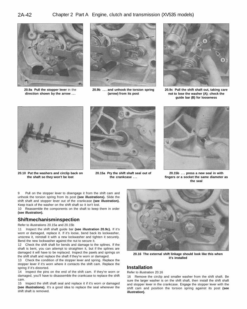
19.4a Install new O-rings in the oil passage housing (arrows) 19.4b . . . and on the strainer
19.5 Push the strainer into the oilpassage housing until it seats securely
20.2 There should be a punch mark nextto the shift lever slot (arrows); if not, make
your own
20.8a Remove the circlip (arrow)...
20.8b . . . and the washer
20 External shift mechanism - removal, inspection andinstallation
Shift lever and pedalRefer to illustration 20.21 Support the bike securely so it can't be knocked over during thisprocedure.2 Look for a punch mark on the end of the lever shaft (seeillustration). This should align with the groove in the lever. If you can'tfind it, make your own punch mark so the lever can be realignedcorrectly during installation.3 Remove the lever pinch bolt (see illustration 20.2). Pull the leveroff the shaft, together with the linkage rod.4 If it's necessary to separate the shift pedal from the footpegassembly, remove the assembly as described in Chapter 7.5 Installation is the reverse of removal. Adjust the linkage as neededwith the nuts on the linkage shaft (see Chapter 1).
Shift mechanism removalRefer to illustrations 20.8a, 20.8b, 20.9a, 20.9b, 20.9c and 20.106 Disconnect the shift lever from the shaft (Steps 1 through 3).7 Remove the clutch housing/primary driven gear (see Section 16).
Remove the alternator cover (see Chapter 8).8 Remove the circlip and washer from the shift shaft (seeillustrations).
2A-42 Chapter 2 Part A Engine, clutch and transmission (XV535 models)
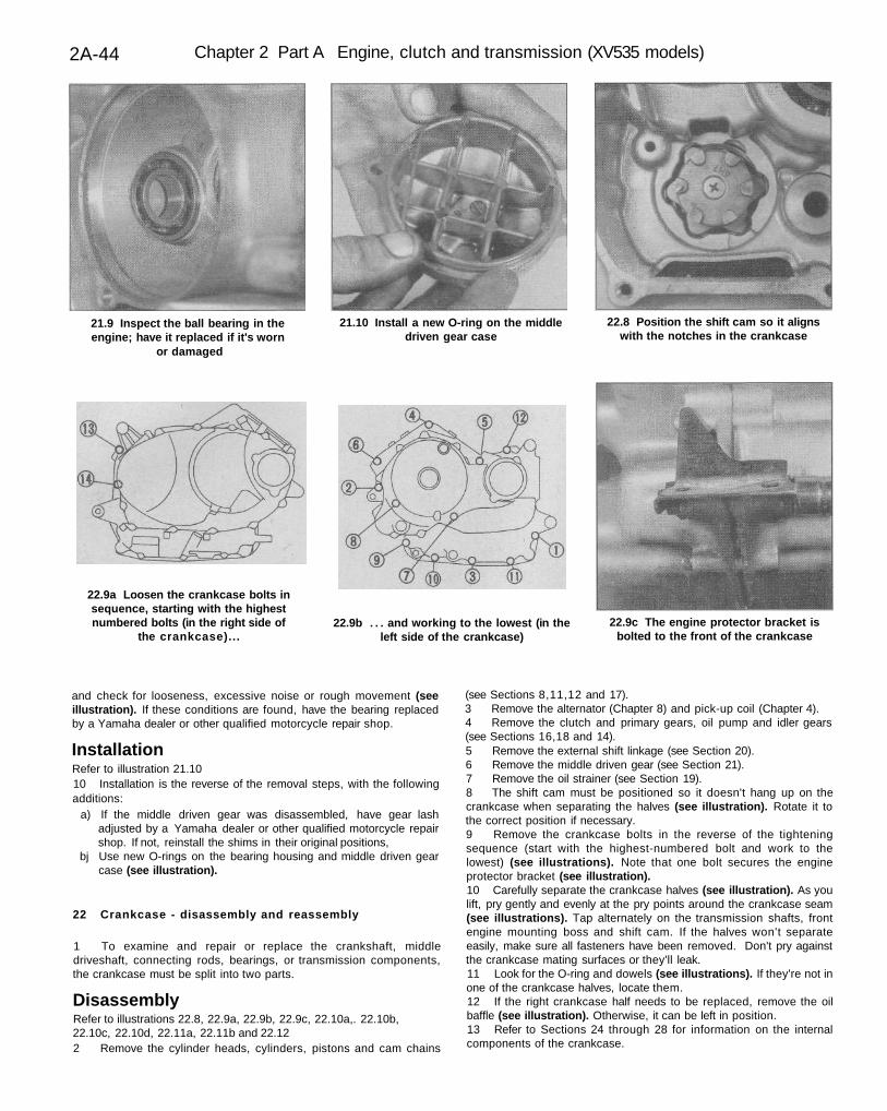
20.9a Pull the stopper lever in thedirection shown by the arrow . . .
20.9b . . . and unhook the torsion spring(arrow) from its post
20.9c Pull the shift shaft out, taking carenot to lose the washer (A); check the
guide bar (B) for looseness
20.10 Put the washers and circlip back onthe shaft so they won't be lost
20.15a Pry the shift shaft seal out ofthe crankcase . . .
20.15b . . . press a new seal in withfingers or a socket the same diameter as
the seal
20.16 The external shift linkage should look like this whenit's installed
9 Pull on the stopper lever to disengage it from the shift cam andunhook the torsion spring from its post (see illustrations). Slide theshift shaft and stopper lever out of the crankcase (see illustration).Keep track of the washer on the shift shaft so it isn't lost.10 Reassemble the components on the shaft to keep them in order(see illustration).
Shift mechanism inspectionRefer to illustrations 20.15a and 20.15b11 Inspect the shift shaft guide bar (see illustration 20.9c). If it'sworn or damaged, replace it. If it's loose, bend back its lockwasher,unscrew it, reinstall it with a new lockwasher and tighten it securely.Bend the new lockwasher against the nut to secure it.12 Check the shift shaft for bends and damage to the splines. If theshaft is bent, you can attempt to straighten it, but if the splines aredamaged it will have to be replaced. Inspect the pawls and springs onthe shift shaft and replace the shaft if they're worn or damaged.13 Check the condition of the stopper lever and spring. Replace thestopper lever if it's worn where it contacts the shift cam. Replace thespring if it's distorted.14 Inspect the pins on the end of the shift cam. If they're worn ordamaged, you'll have to disassemble the crankcase to replace the shiftcam.15 Inspect the shift shaft seal and replace it if it's worn or damaged(see illustrations). It's a good idea to replace the seal whenever theshift shaft is removed.
InstallationRefer to illustration 20.1616 Remove the circlip and smaller washer from the shift shaft. Besure the larger washer is on the shift shaft, then install the shift shaftand stopper lever in the crankcase. Engage the stopper lever with theshift cam and position the torsion spring against its post (seeillustration).

Chapter 2 Part A Engine, clutch and transmission (XV535 models) 2A-43
21.2a Remove the Allen bolts (arrows)... 21.2b . . . and take the middle driven gearcase off
21.3a Remove four bolts . . .
21.3b . . . pull the middle driven gear backfrom the crankcase . . .
21.3c . . . pull out the shims and writedown their locations . . .
21.3d . . . then pull the assembly out ofthe engine
21.4 Remove the O-ring from the housing with a pointed tool
17 Install the plain washer and circlip on the other end of the shiftshaft (see illustrations 20.8b and 20.8a),18 The remainder of installation is the reverse of the removal steps.19 Adjust the shift pedal position (see Chapter 1).20 Check the engine oil level and add some, if necessary (seeChapter 1).
21 Middle driven gear - removal, inspection andinstallation
RemovalRefer to illustrations 21.2a, 21.2b, 21.3a, 21.3b, 21.3c, 21.3d, 21.4and 21.91 Remove the engine from the frame (see Section 5).2 Unbolt the middle gear case from the engine (see illustrations).3 Remove four bolts that secure the bearing housing to the case(see illustration). Remove the bearing housing and any shims, writingdown the number and location of the shims for use during installation(see illustrations).4 Remove the O-ring from the bearing housing (see illustration).
Inspection5 Check the universal joint and ball bearing on the middle drivenshaft for looseness or stiff movement.6 Check the shaft splines and the teeth of the middle driven gear forwear or damage.
7 Check the damper spring for looseness or obvious damage suchas breakage.8 If any of the above conditions exist, have the middle driven geardisassembled and repaired by a Yamaha dealer or other qualifiedmotorcycle repair shop.9 Spin the middle driven gear bearing in the crankcase with fingers
2A-44 Chapter 2 Part A Engine, clutch and transmission (XV535 models)
21.9 Inspect the ball bearing in theengine; have it replaced if it's worn
or damaged
21.10 Install a new O-ring on the middledriven gear case
22.8 Position the shift cam so it alignswith the notches in the crankcase
22.9a Loosen the crankcase bolts insequence, starting with the highestnumbered bolts (in the right side of
the crankcase)...22.9b . . . and working to the lowest (in the
left side of the crankcase)22.9c The engine protector bracket is
bolted to the front of the crankcase
and check for looseness, excessive noise or rough movement (seeillustration). If these conditions are found, have the bearing replacedby a Yamaha dealer or other qualified motorcycle repair shop.
InstallationRefer to illustration 21.1010 Installation is the reverse of the removal steps, with the followingadditions:
a) If the middle driven gear was disassembled, have gear lashadjusted by a Yamaha dealer or other qualified motorcycle repairshop. If not, reinstall the shims in their original positions,
bj Use new O-rings on the bearing housing and middle driven gearcase (see illustration).
22 Crankcase - disassembly and reassembly
1 To examine and repair or replace the crankshaft, middledriveshaft, connecting rods, bearings, or transmission components,the crankcase must be split into two parts.
DisassemblyRefer to illustrations 22.8, 22.9a, 22.9b, 22.9c, 22.10a,. 22.10b,22.10c, 22.10d, 22.11a, 22.11b and 22.122 Remove the cylinder heads, cylinders, pistons and cam chains
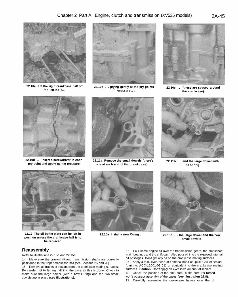
(see Sections 8,11,12 and 17).3 Remove the alternator (Chapter 8) and pick-up coil (Chapter 4).4 Remove the clutch and primary gears, oil pump and idler gears(see Sections 16,18 and 14).5 Remove the external shift linkage (see Section 20).6 Remove the middle driven gear (see Section 21).7 Remove the oil strainer (see Section 19).8 The shift cam must be positioned so it doesn't hang up on thecrankcase when separating the halves (see illustration). Rotate it tothe correct position if necessary.9 Remove the crankcase bolts in the reverse of the tighteningsequence (start with the highest-numbered bolt and work to thelowest) (see illustrations). Note that one bolt secures the engineprotector bracket (see illustration).10 Carefully separate the crankcase halves (see illustration). As youlift, pry gently and evenly at the pry points around the crankcase seam(see illustrations). Tap alternately on the transmission shafts, frontengine mounting boss and shift cam. If the halves won't separateeasily, make sure all fasteners have been removed. Don't pry againstthe crankcase mating surfaces or they'll leak.11 Look for the O-ring and dowels (see illustrations). If they're not inone of the crankcase halves, locate them.12 If the right crankcase half needs to be replaced, remove the oilbaffle (see illustration). Otherwise, it can be left in position.13 Refer to Sections 24 through 28 for information on the internalcomponents of the crankcase.
Chapter 2 Part A Engine, clutch and transmission (XV535 models) 2A-45
22.10a Lift the right crankcase half offthe left half . . .
22.10b . . . prying gently at the pry pointsif necessary .. .
22.10c . . . (these are spaced aroundthe crankcase)
22.10d . . . insert a screwdriver in eachpry point and apply gentle pressure
22.11a Remove the small dowels (there'sone at each end of the crankcase)...
22.11b . . . and the large dowel withits O-ring
22.12 The oil baffle plate can be left inposition unless the crankcase half is to
be replaced
22.15a Install a new O-ring . 22.15b . . . the large dowel and the twosmall dowels
ReassemblyRefer to illustrations 22.15a and 22.15b14 Make sure the crankshaft and transmission shafts are correctlypositioned in the upper crankcase half (see Sections 25 and 28).15 Remove all traces of sealant from the crankcase mating surfaces.Be careful not to let any fall into the case as this is done. Check tomake sure the large dowel (with a new O-ring) and the two smalldowels are in place (see illustrations).
16 Pour some engine oil over the transmission gears, the crankshaftmain bearings and the shift cam. Also pour oil into the exposed internaloil passages. Don't get any oil on the crankcase mating surfaces.17 Apply a thin, even bead of Yamaha Bond or Quick Gasket sealant(part no. ACC-11001-05-01) or equivalent to the crankcase matingsurfaces. Caution: Don't apply an excessive amount of sealant.18 Check the position of the shift cam. Make sure it's turnedwon't obstruct assembly of the cases (see illustration 22.8).19 Carefully assemble the crankcase halves over the d:
2A-46 Chapter 2 Part A Engine, clutch and transmission (XV535 models)
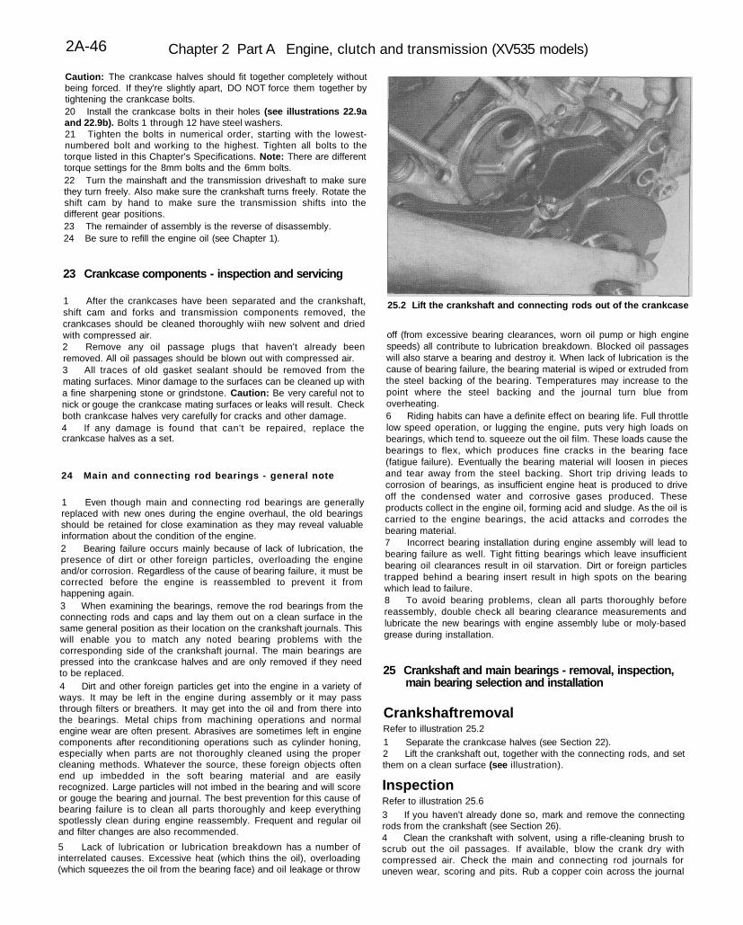
25.2 Lift the crankshaft and connecting rods out of the crankcase
Caution: The crankcase halves should fit together completely withoutbeing forced. If they're slightly apart, DO NOT force them together bytightening the crankcase bolts.20 Install the crankcase bolts in their holes (see illustrations 22.9aand 22.9b). Bolts 1 through 12 have steel washers.21 Tighten the bolts in numerical order, starting with the lowest-numbered bolt and working to the highest. Tighten all bolts to thetorque listed in this Chapter's Specifications. Note: There are differenttorque settings for the 8mm bolts and the 6mm bolts.22 Turn the mainshaft and the transmission driveshaft to make surethey turn freely. Also make sure the crankshaft turns freely. Rotate theshift cam by hand to make sure the transmission shifts into thedifferent gear positions.23 The remainder of assembly is the reverse of disassembly.24 Be sure to refill the engine oil (see Chapter 1).
23 Crankcase components - inspection and servicing
1 After the crankcases have been separated and the crankshaft,shift cam and forks and transmission components removed, thecrankcases should be cleaned thoroughly wiih new solvent and driedwith compressed air.2 Remove any oil passage plugs that haven't already beenremoved. All oil passages should be blown out with compressed air.3 All traces of old gasket sealant should be removed from themating surfaces. Minor damage to the surfaces can be cleaned up witha fine sharpening stone or grindstone. Caution: Be very careful not tonick or gouge the crankcase mating surfaces or leaks will result. Checkboth crankcase halves very carefully for cracks and other damage.4 If any damage is found that can't be repaired, replace thecrankcase halves as a set.
24 Main and connecting rod bearings - general note
1 Even though main and connecting rod bearings are generallyreplaced with new ones during the engine overhaul, the old bearingsshould be retained for close examination as they may reveal valuableinformation about the condition of the engine.2 Bearing failure occurs mainly because of lack of lubrication, thepresence of dirt or other foreign particles, overloading the engineand/or corrosion. Regardless of the cause of bearing failure, it must becorrected before the engine is reassembled to prevent it fromhappening again.3 When examining the bearings, remove the rod bearings from theconnecting rods and caps and lay them out on a clean surface in thesame general position as their location on the crankshaft journals. Thiswill enable you to match any noted bearing problems with thecorresponding side of the crankshaft journal. The main bearings arepressed into the crankcase halves and are only removed if they needto be replaced.4 Dirt and other foreign particles get into the engine in a variety ofways. It may be left in the engine during assembly or it may passthrough filters or breathers. It may get into the oil and from there intothe bearings. Metal chips from machining operations and normalengine wear are often present. Abrasives are sometimes left in enginecomponents after reconditioning operations such as cylinder honing,especially when parts are not thoroughly cleaned using the propercleaning methods. Whatever the source, these foreign objects oftenend up imbedded in the soft bearing material and are easilyrecognized. Large particles will not imbed in the bearing and will scoreor gouge the bearing and journal. The best prevention for this cause ofbearing failure is to clean all parts thoroughly and keep everythingspotlessly clean during engine reassembly. Frequent and regular oiland filter changes are also recommended.
5 Lack of lubrication or lubrication breakdown has a number ofinterrelated causes. Excessive heat (which thins the oil), overloading(which squeezes the oil from the bearing face) and oil leakage or throw
off (from excessive bearing clearances, worn oil pump or high enginespeeds) all contribute to lubrication breakdown. Blocked oil passageswill also starve a bearing and destroy it. When lack of lubrication is thecause of bearing failure, the bearing material is wiped or extruded fromthe steel backing of the bearing. Temperatures may increase to thepoint where the steel backing and the journal turn blue fromoverheating.6 Riding habits can have a definite effect on bearing life. Full throttlelow speed operation, or lugging the engine, puts very high loads onbearings, which tend to. squeeze out the oil film. These loads cause thebearings to flex, which produces fine cracks in the bearing face(fatigue failure). Eventually the bearing material will loosen in piecesand tear away from the steel backing. Short trip driving leads tocorrosion of bearings, as insufficient engine heat is produced to driveoff the condensed water and corrosive gases produced. Theseproducts collect in the engine oil, forming acid and sludge. As the oil iscarried to the engine bearings, the acid attacks and corrodes thebearing material.7 Incorrect bearing installation during engine assembly will lead tobearing failure as well. Tight fitting bearings which leave insufficientbearing oil clearances result in oil starvation. Dirt or foreign particlestrapped behind a bearing insert result in high spots on the bearingwhich lead to failure.8 To avoid bearing problems, clean all parts thoroughly beforereassembly, double check all bearing clearance measurements andlubricate the new bearings with engine assembly lube or moly-basedgrease during installation.
25 Crankshaft and main bearings - removal, inspection,main bearing selection and installation
Crankshaft removalRefer to illustration 25.21 Separate the crankcase halves (see Section 22).2 Lift the crankshaft out, together with the connecting rods, and setthem on a clean surface (see illustration).
InspectionRefer to illustration 25.63 If you haven't already done so, mark and remove the connectingrods from the crankshaft (see Section 26).4 Clean the crankshaft with solvent, using a rifle-cleaning brush toscrub out the oil passages. If available, blow the crank dry withcompressed air. Check the main and connecting rod journals foruneven wear, scoring and pits. Rub a copper coin across the journal
Chapter 2 Part A Engine, clutch and transmission (XV535 models) 2A-47
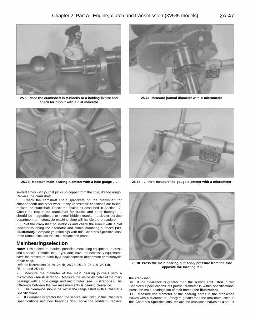
25.6 Place the crankshaft in V-blocks or a holding fixture andcheck for runout with a dial indicator
25.7a Measure journal diameter with a micrometer
25.7b Measure main bearing diameter with a hole gauge . . . 25.7c . . . then measure the gauge diameter with a micrometer
25.10 Press the main bearing out; apply pressure from the sideopposite the locating tab
several times - if a journal picks up copper from the coin, it's too rough.Replace the crankshaft.5 Check the camshaft chain sprockets on the crankshaft forchipped teeth and other wear. If any undesirable conditions are found,replace the crankshaft. Check the chains as described in Section 17.Check the rest of the crankshaft for cracks and other damage. Itshould be magnafluxed to reveal hidden cracks - a dealer servicedepartment or motorcycle machine shop will handle the procedure.6 Set the crankshaft on V-blocks and check the runout with a dialindicator touching the alternator and clutch mounting surfaces (seeillustration). Compare your findings with this Chapter's Specifications.If the runout exceeds the limit, replace the crank.
Main bearing selectionNote: This procedure requires precision measuring equipment, a pressand a special Yamaha tool. If you don't have the necessary equipment,have the procedure done by a dealer service department or motorcyclerepair shop.Refer to illustrations 25.7a, 25.7b, 25.7c, 25.10, 25.11a, 25.11b,25.11c and 25.11d7 Measure the diameter of the main bearing journals with amicrometer (see illustration). Measure the inside diameter of the mainbearings with a hole gauge and micrometer (see illustrations). Thedifference between the two measurements is bearing clearance.8 The clearance should be within the range listed in this Chapter'sSpecifications.9 If clearance is greater than the service limit listed in this Chapter'sSpecifications and new bearings don't solve the problem, replace
the crankshaft.10 If the clearance is greater than the service limit listed in thisChapter's Specifications but journal diameter is within specifications,press the main bearings out of their bores (see illustration).11 Measure the diameter of the bearing bores in the crankcasehalves with a micrometer. If they're greater than the maximum listed inthis Chapter's Specifications, replace the crankcase halves as a set. If
2A-48 Chapter 2 Part A Engine, clutch and transmission (XV535 models)
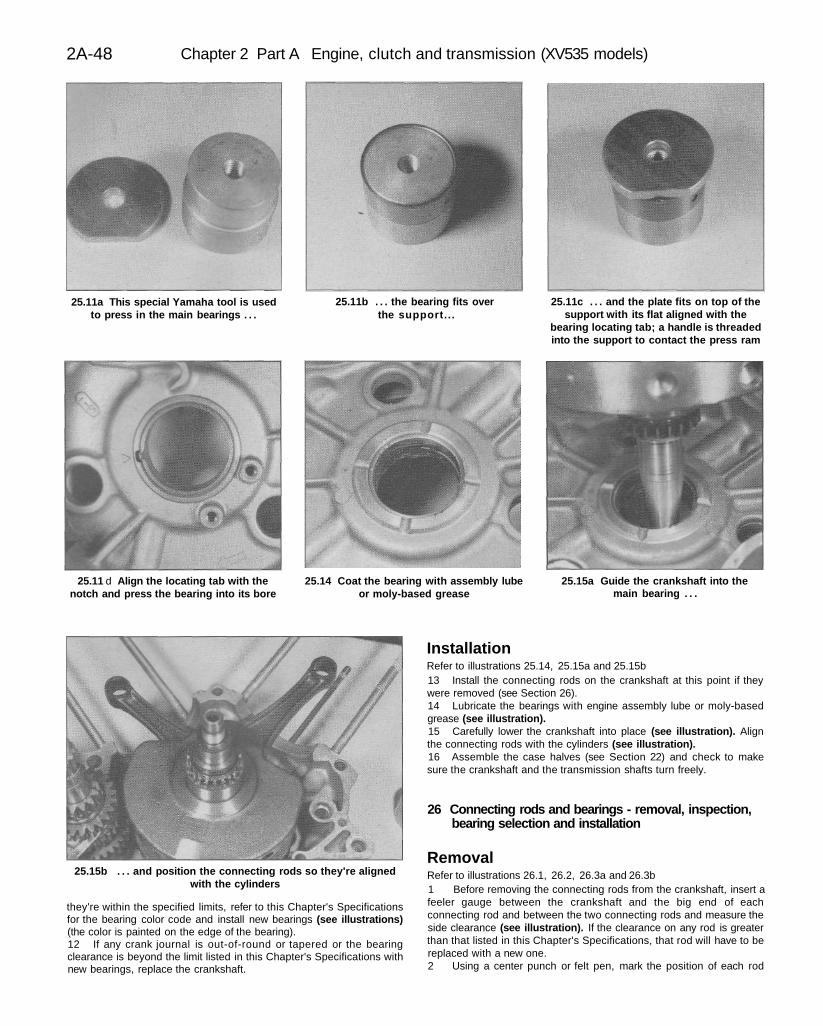
25.11a This special Yamaha tool is usedto press in the main bearings . . .
25.11b . . . the bearing fits overthe support...
25.11c . . . and the plate fits on top of thesupport with its flat aligned with the
bearing locating tab; a handle is threadedinto the support to contact the press ram
25.11 d Align the locating tab with thenotch and press the bearing into its bore
25.14 Coat the bearing with assembly lubeor moly-based grease
25.15a Guide the crankshaft into themain bearing . . .
25.15b . . . and position the connecting rods so they're alignedwith the cylinders
they're within the specified limits, refer to this Chapter's Specificationsfor the bearing color code and install new bearings (see illustrations)(the color is painted on the edge of the bearing).12 If any crank journal is out-of-round or tapered or the bearingclearance is beyond the limit listed in this Chapter's Specifications withnew bearings, replace the crankshaft.
InstallationRefer to illustrations 25.14, 25.15a and 25.15b13 Install the connecting rods on the crankshaft at this point if theywere removed (see Section 26).14 Lubricate the bearings with engine assembly lube or moly-basedgrease (see illustration).15 Carefully lower the crankshaft into place (see illustration). Alignthe connecting rods with the cylinders (see illustration).16 Assemble the case halves (see Section 22) and check to makesure the crankshaft and the transmission shafts turn freely.
26 Connecting rods and bearings - removal, inspection,bearing selection and installation
RemovalRefer to illustrations 26.1, 26.2, 26.3a and 26.3b1 Before removing the connecting rods from the crankshaft, insert afeeler gauge between the crankshaft and the big end of eachconnecting rod and between the two connecting rods and measure theside clearance (see illustration). If the clearance on any rod is greaterthan that listed in this Chapter's Specifications, that rod will have to bereplaced with a new one.2 Using a center punch or felt pen, mark the position of each rod

Chapter 2 Part A Engine, clutch and transmission (XV535 models) 2A-49
26.1 Measure big end play between the two rods and betweenthe rods and crankshaft
26.2 Label the rods and caps according to their position on the 2Acrankshaft (left or right)
26.3a Undo the connecting rod nuts26.3b . . . and take off the caps
26.5 Slip the piston pin into the rod and rock it back-and-forth tocheck for looseness
and cap, relative to its position on the crankshaft (left or right) (seeillustration).3 Unscrew the bearing cap nuts, separate the cap from the rod,then detach the rod from the crankshaft (see illustrations). If the capis stuck, tap on the ends of the rod bolts with a sofMaced hammer tofree them.4 Roll the bearing inserts sideways to separate them from the rodsand caps. Keep them in order so they can be reinstalled in their original
locations. Wash the parts in solvent and dry them with compressed air,if available.
InspectionRefer to illustration 26.55 Check the connecting rods for cracks and other obvious damage.Lubricate the piston pin for each rod, install it in the proper rod andcheck for play (see illustration). If it wobbles, replace the connectingrod and/or the pin.6 Examine the connecting rod bearing inserts. If they are scored,badly scuffed or appear to have been seized, new bearings must beinstalled. Always replace the bearings in the connecting rods as a set.If they are badly damaged, check the corresponding crankshaftjournal. Evidence of extreme heat, such as discoloration, indicates thatlubrication failure has occurred. Be sure to thoroughly check the oilpump and pressure relief valves as well as ail oil holes and passagesbefore reassembling the engine.7 Have the rods checked for twist and bending at a dealer servicedepartment or other motorcycle repair shop.
Connecting rod bearing selectionRefer to illustrations 26.11, 26.13, 26.18a, 26.18b and 26.18c8 If the bearings and journals appear to be in good condition, checkthe oil clearances as follows:9 Start with the rod for one cylinder. Wipe the bearing inserts andthe connecting rod and cap clean, using a lint-free cloth.10 Install the bearing inserts in the connecting rod and cap. Makesure the tab on the bearing engages with the no111 Wipe off the connecting rod journal with a lint-tree

2A-50 Chapter 2 Part A Engine, clutch and transmission (XV535 models)
26.11 Lay a strip of Plastigage onthe journal, parallel to the
crankshaft centerline
26.13 Place the Plastigage scale next tothe flattened Plastigage to measure the
bearing clearance
26.18a The number on the connectingrod (A) is used for bearing selection; theletter (B) is used to align the cap and rod
during reassembly
26.18b The number on the rod is usedtogether with the number on thecrankshaft to select rod bearings
26.18c The color code is painted on theside of the bearing
26.20a Be sure the tab fits in the notchand the oil hole in the upper bearing
aligns with the oil hole in the connectingrod (arrows)
strip of Plastigage (type HPG-1) across the top of the journal, parallelwith the journal axis (see illustration).12 Position the connecting rod on the journal, then install the rod capand nuts. Tighten the nuts to the torque listed in this Chapter's Specifi-cations, but don't allow the connecting rod to rotate at all.13 Unscrew the nuts and remove the connecting rod and cap fromthe journal, being very careful not to disturb the Plastigage.. Comparethe width of the crushed Plastigage to the scale printed in thePlastigage envelope to determine the bearing oil clearance (seeillustration).14 If the clearance is within the range listed in this Chapter's Specifi-cations and the bearings are in perfect condition, they can be reused. Ifthe clearance is greater than the wear limit, replace the bearing insertswith new inserts that have the same color code, then check theclearance once again. Always replace all of the inserts at the sametime.15 The clearance should be within the range listed in this Chapter'sSpecifications.16 If the clearance is greater than the maximum clearance listed inthis Chapter's Specifications, measure the diameter of the connectingrod journal with a micrometer. Yamaha doesn't provide diameter orwear limit specifications, but by measuring the diameter at a number ofpoints around the journal's circumference, you'll be able to determinewhether or not the journal is out-of-round. Take the measurement ateach end of the journal to determine if the journal is tapered.17 If any journal is tapered or, out-of-round or bearing clearance is
beyond the maximum listed in this Chapter's Specifications (with newbearings), replace the crankshaft.18 Each connecting rod has a 3 or 4 stamped on it in ink (seeillustration). Subtract this number from the connecting rod journalnumber on the crankshaft to get a bearing number (see illustration).For example, the number on the connecting rod shown in theaccompanying illustration is 4. The corresponding number for thatconnecting rod's journal, stamped into the crankshaft, is 2. Subtracting2 from 4 produces 2, which is the bearing number for that journal'.According to the accompanying chart, bearing no. 2 is color-codedblack (see illustration). The color codes are painted on the edges ofthe bearings (see illustration).19 Repeat the bearing selection procedure for the remainingconnecting rods.
InstallationRefer to illustrations 26.20a, 26.20b, 26.21a, 26.21b and 26.2220 Wipe off the bearing inserts, connecting rods and caps. Install theinserts into the rods and caps, using your hands only, making sure thetabs on the inserts engage with the notches in the rods and caps (seeillustration). When all the inserts are installed, lubricate them withengine assembly lube or moly-based grease (see illustration). Don'tget any lubricant on the mating surfaces of the rod or cap.21 Assemble each connecting rod to its proper journal, referring tothe previously applied cylinder numbers. Make sure the Y mark on therod is toward the outside of the engine (see illustration). Also, the
Chapter 2 Part A Engine, clutch and transmission (XV535 models) 2A-51
26.20b Coat the bearings with assemblylube or moly-based grease
26.21a The Y mark on the connecting rod(arrow) faces the outside of the engine
26.21b If the halves of the letter stampedon the rod and cap don't fit together
perfectly, the wrong cap is on the rod (orthe cap is on backwards)
26.22 Tighten to the specified torque instages (see text)
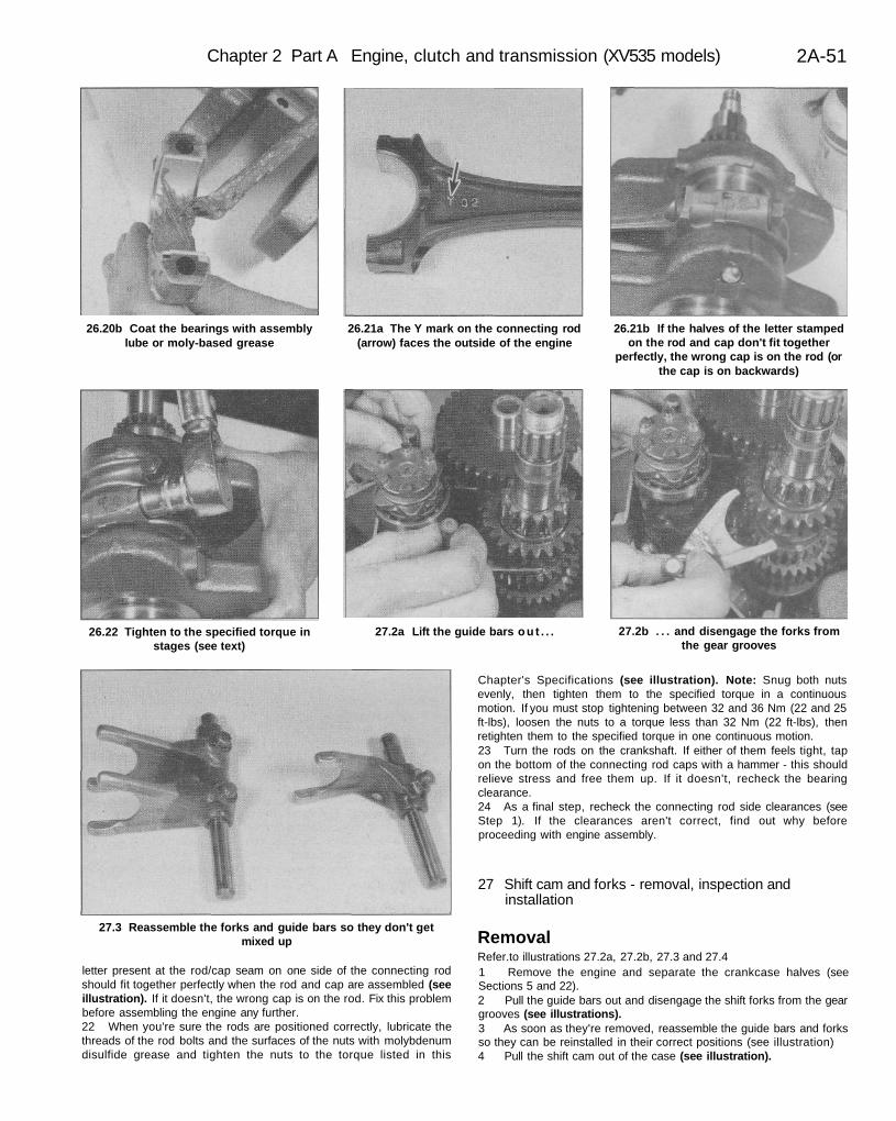
27.2a Lift the guide bars o u t . . . 27.2b . . . and disengage the forks fromthe gear grooves
27.3 Reassemble the forks and guide bars so they don't getmixed up
letter present at the rod/cap seam on one side of the connecting rodshould fit together perfectly when the rod and cap are assembled (seeillustration). If it doesn't, the wrong cap is on the rod. Fix this problembefore assembling the engine any further.22 When you're sure the rods are positioned correctly, lubricate thethreads of the rod bolts and the surfaces of the nuts with molybdenumdisulfide grease and tighten the nuts to the torque listed in this
Chapter's Specifications (see illustration). Note: Snug both nutsevenly, then tighten them to the specified torque in a continuousmotion. If you must stop tightening between 32 and 36 Nm (22 and 25ft-lbs), loosen the nuts to a torque less than 32 Nm (22 ft-lbs), thenretighten them to the specified torque in one continuous motion.23 Turn the rods on the crankshaft. If either of them feels tight, tapon the bottom of the connecting rod caps with a hammer - this shouldrelieve stress and free them up. If it doesn't, recheck the bearingclearance.24 As a final step, recheck the connecting rod side clearances (seeStep 1). If the clearances aren't correct, find out why beforeproceeding with engine assembly.
27 Shift cam and forks - removal, inspection andinstallation
RemovalRefer.to illustrations 27.2a, 27.2b, 27.3 and 27.41 Remove the engine and separate the crankcase halves (seeSections 5 and 22).2 Pull the guide bars out and disengage the shift forks from the geargrooves (see illustrations).3 As soon as they're removed, reassemble the guide bars and forksso they can be reinstalled in their correct positions (see illustration)4 Pull the shift cam out of the case (see illustration).
2A-52 Chapter 2 Part A Engine, clutch and transmission (XV535 models)
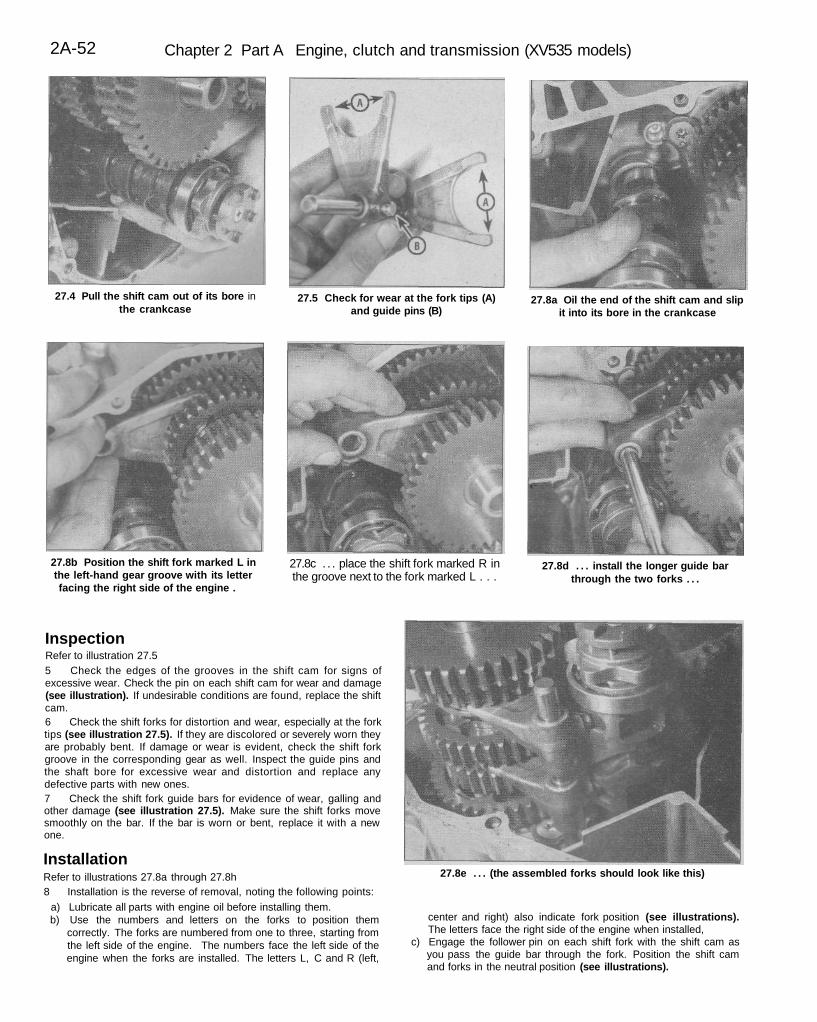
27.4 Pull the shift cam out of its bore inthe crankcase
27.5 Check for wear at the fork tips (A)and guide pins (B)
27.8a Oil the end of the shift cam and slipit into its bore in the crankcase
27.8b Position the shift fork marked L inthe left-hand gear groove with its letterfacing the right side of the engine .
27.8c . . . place the shift fork marked R inthe groove next to the fork marked L . . .
27.8d . . . install the longer guide barthrough the two forks . . .
27.8e . . . (the assembled forks should look like this)
InspectionRefer to illustration 27.55 Check the edges of the grooves in the shift cam for signs ofexcessive wear. Check the pin on each shift cam for wear and damage(see illustration). If undesirable conditions are found, replace the shiftcam.6 Check the shift forks for distortion and wear, especially at the forktips (see illustration 27.5). If they are discolored or severely worn theyare probably bent. If damage or wear is evident, check the shift forkgroove in the corresponding gear as well. Inspect the guide pins andthe shaft bore for excessive wear and distortion and replace anydefective parts with new ones.7 Check the shift fork guide bars for evidence of wear, galling andother damage (see illustration 27.5). Make sure the shift forks movesmoothly on the bar. If the bar is worn or bent, replace it with a newone.
InstallationRefer to illustrations 27.8a through 27.8h8 Installation is the reverse of removal, noting the following points:
a) Lubricate all parts with engine oil before installing them.b) Use the numbers and letters on the forks to position them
correctly. The forks are numbered from one to three, starting fromthe left side of the engine. The numbers face the left side of theengine when the forks are installed. The letters L, C and R (left,
center and right) also indicate fork position (see illustrations).The letters face the right side of the engine when installed,
c) Engage the follower pin on each shift fork with the shift cam asyou pass the guide bar through the fork. Position the shift camand forks in the neutral position (see illustrations).
Chapter 2 Part A Engine, clutch and transmission (XV535 models) 2A-53
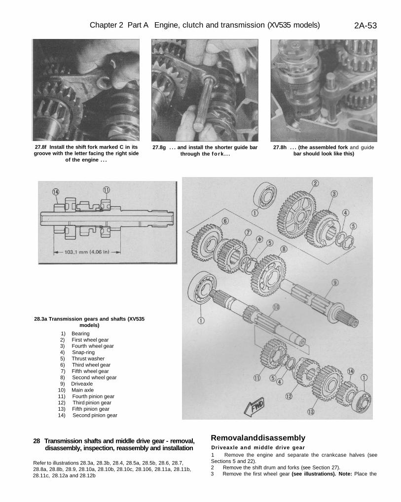
27.8f Install the shift fork marked C in itsgroove with the letter facing the right side
of the engine . . .
27.8g . . . and install the shorter guide barthrough the fork . . .
27.8h . . . (the assembled fork and guidebar should look like this)
28.3a Transmission gears and shafts (XV535models)
1) Bearing2) First wheel gear3) Fourth wheel gear4) Snap-ring5) Thrust washer6) Third wheel gear7) Fifth wheel gear8) Second wheel gear9) Driveaxle
10) Main axle11) Fourth pinion gear12) Third pinion gear13) Fifth pinion gear14) Second pinion gear
28 Transmission shafts and middle drive gear - removal,disassembly, inspection, reassembly and installation
Refer to illustrations 28.3a, 28.3b, 28.4, 28.5a, 28.5b, 28.6, 28.7,28.8a, 28.8b, 28.9, 28.10a, 28.10b, 28.10c, 28.106, 28.11a, 28.11b,28.11c, 28.12a and 28.12b
Removal and disassemblyDriveaxle and middle drive gear1 Remove the engine and separate the crankcase halves (seeSections 5 and 22).2 Remove the shift drum and forks (see Section 27).3 Remove the first wheel gear (see illustrations). Note: Place the
2A-54 Chapter 2 Part A Engine, clutch and transmission (XV535 models)
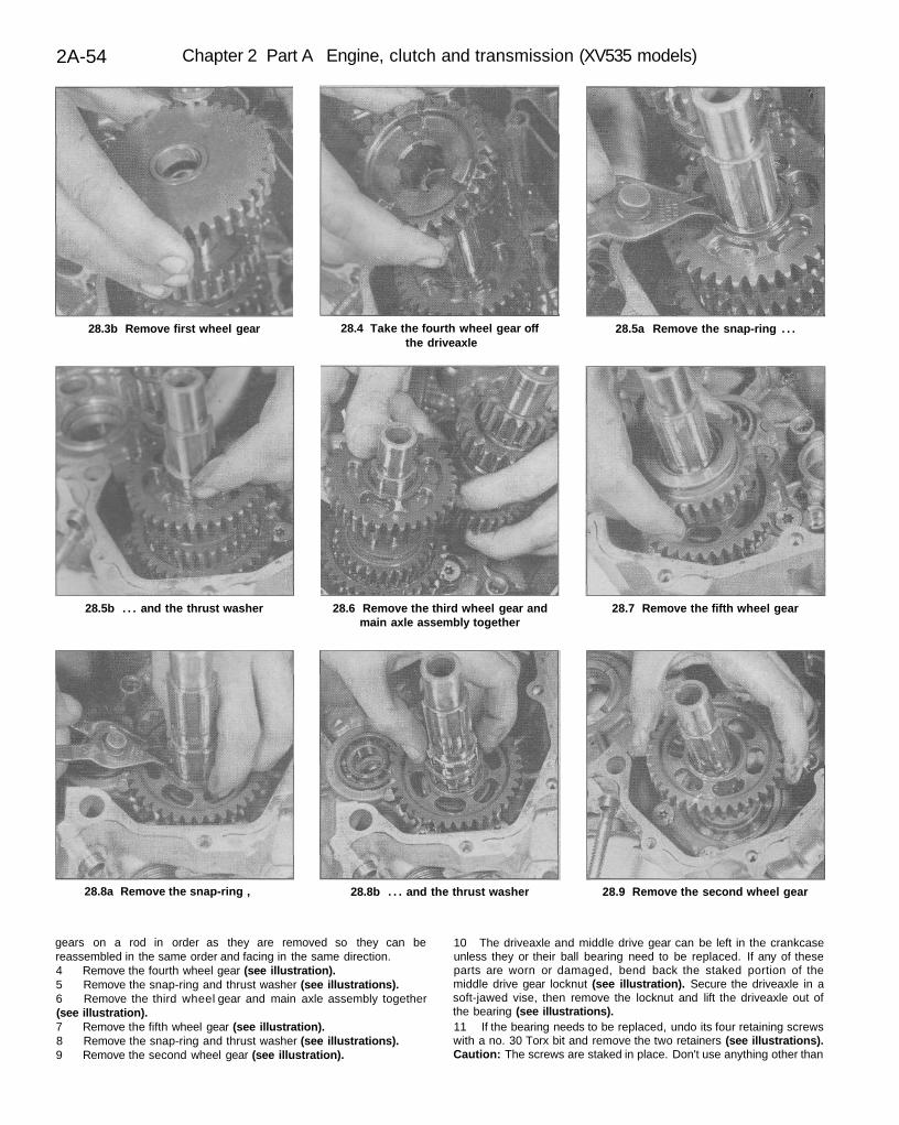
28.3b Remove first wheel gear 28.4 Take the fourth wheel gear offthe driveaxle
28.5a Remove the snap-ring . . .
28.5b . . . and the thrust washer 28.6 Remove the third wheel gear andmain axle assembly together
28.7 Remove the fifth wheel gear
28.8a Remove the snap-ring , 28.8b . . . and the thrust washer 28.9 Remove the second wheel gear
gears on a rod in order as they are removed so they can bereassembled in the same order and facing in the same direction.4 Remove the fourth wheel gear (see illustration).5 Remove the snap-ring and thrust washer (see illustrations).6 Remove the third wheel gear and main axle assembly together(see illustration).7 Remove the fifth wheel gear (see illustration).8 Remove the snap-ring and thrust washer (see illustrations).9 Remove the second wheel gear (see illustration).
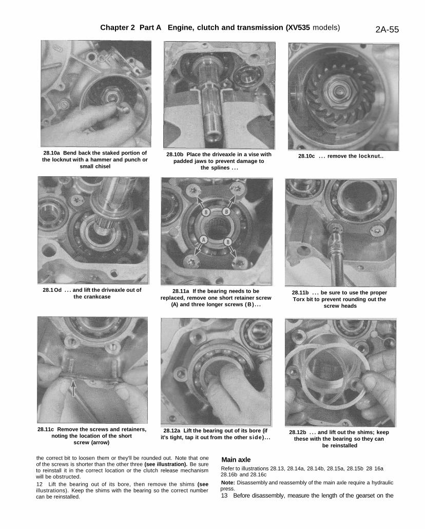
10 The driveaxle and middle drive gear can be left in the crankcaseunless they or their ball bearing need to be replaced. If any of theseparts are worn or damaged, bend back the staked portion of themiddle drive gear locknut (see illustration). Secure the driveaxle in asoft-jawed vise, then remove the locknut and lift the driveaxle out ofthe bearing (see illustrations).11 If the bearing needs to be replaced, undo its four retaining screwswith a no. 30 Torx bit and remove the two retainers (see illustrations).Caution: The screws are staked in place. Don't use anything other than
Chapter 2 Part A Engine, clutch and transmission (XV535 models) 2A-55
28.10a Bend back the staked portion ofthe locknut with a hammer and punch or
small chisel
28.10b Place the driveaxle in a vise withpadded jaws to prevent damage to
the splines . . .
28.10c . . . remove the locknut..
28.1 Od . . . and lift the driveaxle out ofthe crankcase
28.11a If the bearing needs to bereplaced, remove one short retainer screw
(A) and three longer screws ( B ) . . .
28.11b . . . be sure to use the properTorx bit to prevent rounding out the
screw heads
28.11c Remove the screws and retainers,noting the location of the short
screw (arrow)
28.12a Lift the bearing out of its bore (ifit's tight, tap it out from the other side) . . .
28.12b . . . and lift out the shims; keepthese with the bearing so they can
be reinstalled
the correct bit to loosen them or they'll be rounded out. Note that oneof the screws is shorter than the other three (see illustration). Be sureto reinstall it in the correct location or the clutch release mechanismwill be obstructed.12 Lift the bearing out of its bore, then remove the shims (seeillustrations). Keep the shims with the bearing so the correct numbercan be reinstalled.
Main axleRefer to illustrations 28.13, 28.14a, 28.14b, 28.15a, 28.15b 28 16a28.16b and 28.16c
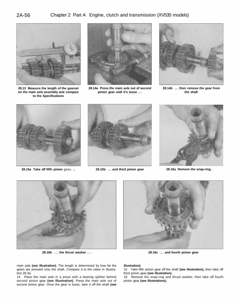
Note: Disassembly and reassembly of the main axle require a hydraulicpress.13 Before disassembly, measure the length of the gearset on the
2A-56 Chapter 2 Part A Engine, clutch and transmission (XV535 models)
28.13 Measure the length of the gearseton the main axle assembly and compare
to the Specifications
28.14a Press the main axle out of secondpinion gear until it's loose . . .
28.14b . . . then remove the gear fromthe shaft
28.15a Take off fifth pinion gear. .. 28.15b . . . and third pinion gear 28.16a Remove the snap-ring .
28.16b . . . the thrust washer . . . 28.16c . . . and fourth pinion gear
main axle (see illustration). The length is determined by how far thegears are pressed onto the shaft. Compare it to the value in illustra-tion 28.3a.14 Place the main axle in a press with a bearing splitter behindsecond pinion gear (see illustration). Press the main axle out ofsecond pinion gear. Once the gear is loose, take it off the shaft (see
illustration).15 Take fifth pinion gear off the shaft (see illustration), then take offthird pinion gear (see illustration).16 Remove the snap-ring and thrust washer, then take off fourthpinion gear (see illustrations).
Chapter 2 Part A Engine, clutch and transmission (XV535 models) 2A-57
28.21 Check the shafts for runout with V-biocks and adial indicator
28.22a Stake the bearing retainer screws . . .
28.22b . . . and the middle drive gear locknut 28.23a The assembled main axle should look like this
28.23b Press second pinion gear onto the shaft until the gearsetis the specified length
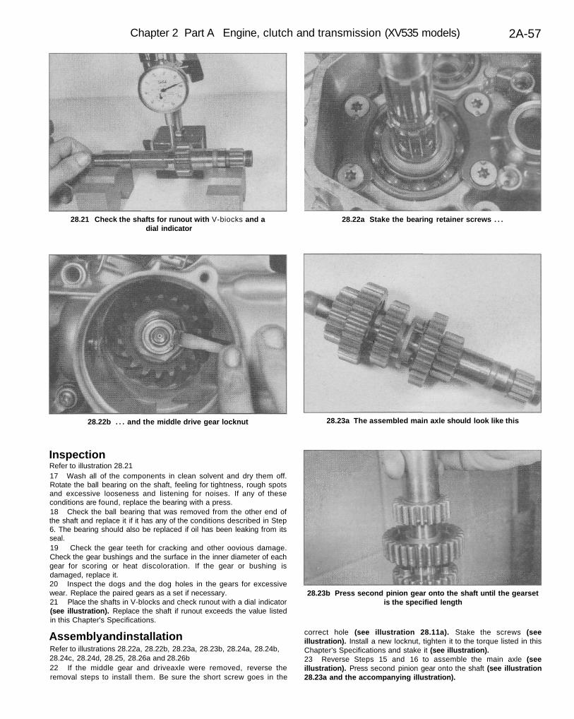
InspectionRefer to illustration 28.2117 Wash all of the components in clean solvent and dry them off.Rotate the ball bearing on the shaft, feeling for tightness, rough spotsand excessive looseness and listening for noises. If any of theseconditions are found, replace the bearing with a press.18 Check the ball bearing that was removed from the other end ofthe shaft and replace it if it has any of the conditions described in Step6. The bearing should also be replaced if oil has been leaking from itsseal.19 Check the gear teeth for cracking and other oovious damage.Check the gear bushings and the surface in the inner diameter of eachgear for scoring or heat discoloration. If the gear or bushing isdamaged, replace it.20 Inspect the dogs and the dog holes in the gears for excessivewear. Replace the paired gears as a set if necessary.21 Place the shafts in V-blocks and check runout with a dial indicator(see illustration). Replace the shaft if runout exceeds the value listedin this Chapter's Specifications.
Assembly and installationRefer to illustrations 28.22a, 28.22b, 28.23a, 28.23b, 28.24a, 28.24b,28.24c, 28.24d, 28.25, 28.26a and 28.26b22 If the middle gear and driveaxle were removed, reverse theremoval steps to install them. Be sure the short screw goes in the
correct hole (see illustration 28.11a). Stake the screws (seeillustration). Install a new locknut, tighten it to the torque listed in thisChapter's Specifications and stake it (see illustration).23 Reverse Steps 15 and 16 to assemble the main axle (seeillustration). Press second pinion gear onto the shaft (see illustration28.23a and the accompanying illustration).
2A-58 Chapter 2 Part A Engine, clutch and transmission (XV535 models)
28.24a Install second wheel gear 28.24b . . . the thrust washer . . . 28.24c . . . the snap-ring . . .
28.24d . . . and fifth wheel gear 28.25 Install third wheel gear on the main axle at the same timeyou install the driveaxle in its bearing
28.26a When the gears are in the neutral position, the gear dogs(arrows) are not engaged with the slots in the gears next to them
and the gears can be turned independently of each other(driveaxle shown)
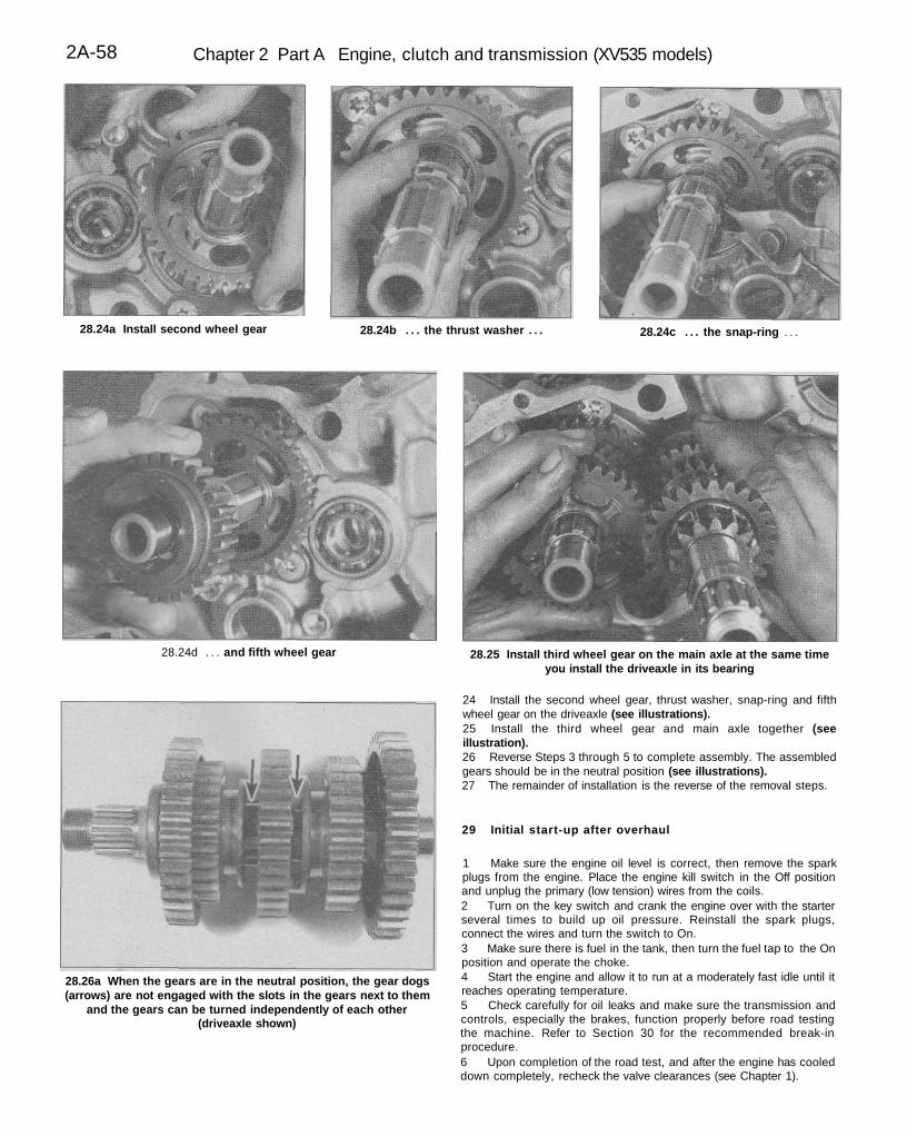
24 Install the second wheel gear, thrust washer, snap-ring and fifthwheel gear on the driveaxle (see illustrations).25 Install the third wheel gear and main axle together (seeillustration).26 Reverse Steps 3 through 5 to complete assembly. The assembledgears should be in the neutral position (see illustrations).27 The remainder of installation is the reverse of the removal steps.
29 Initial start-up after overhaul
1 Make sure the engine oil level is correct, then remove the sparkplugs from the engine. Place the engine kill switch in the Off positionand unplug the primary (low tension) wires from the coils.2 Turn on the key switch and crank the engine over with the starterseveral times to build up oil pressure. Reinstall the spark plugs,connect the wires and turn the switch to On.3 Make sure there is fuel in the tank, then turn the fuel tap to the Onposition and operate the choke.4 Start the engine and allow it to run at a moderately fast idle until itreaches operating temperature.5 Check carefully for oil leaks and make sure the transmission andcontrols, especially the brakes, function properly before road testingthe machine. Refer to Section 30 for the recommended break-inprocedure.6 Upon completion of the road test, and after the engine has cooleddown completely, recheck the valve clearances (see Chapter 1).
Chapter 2 Part A Engine, clutch and transmission (XV535 models) 2A-59
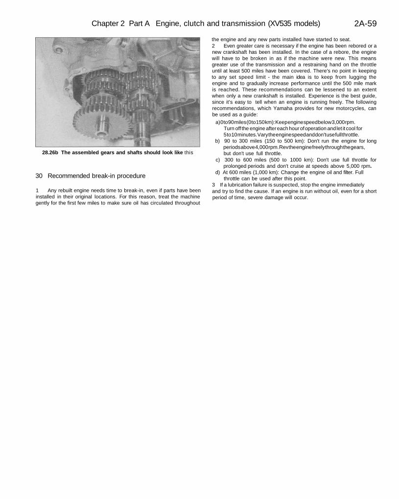
28.26b The assembled gears and shafts should look like this
30 Recommended break-in procedure
1 Any rebuilt engine needs time to break-in, even if parts have beeninstalled in their original locations. For this reason, treat the machinegently for the first few miles to make sure oil has circulated throughout
the engine and any new parts installed have started to seat.2 Even greater care is necessary if the engine has been rebored or anew crankshaft has been installed. In the case of a rebore, the enginewill have to be broken in as if the machine were new. This meansgreater use of the transmission and a restraining hand on the throttleuntil at least 500 miles have been covered. There's no point in keepingto any set speed limit - the main idea is to keep from lugging theengine and to gradually increase performance until the 500 mile markis reached. These recommendations can be lessened to an extentwhen only a new crankshaft is installed. Experience is the best guide,since it's easy to tell when an engine is running freely. The followingrecommendations, which Yamaha provides for new motorcycles, canbe used as a guide:
a) 0 to 90 miles (0 to 150 km): Keep engine speed below 3,000 rpm.Turn off the engine after each hour of operation and let it cool for5 to 10 minutes. Vary the engine speed and don't use full throttle.
b) 90 to 300 miles (150 to 500 km): Don't run the engine for longperiods above 4,000 rpm. Rev the engine freely through the gears,but don't use full throttle.
c) 300 to 600 miles (500 to 1000 km): Don't use full throttle forprolonged periods and don't cruise at speeds above 5,000 rpm.
d) At 600 miles (1,000 km): Change the engine oil and filter. Fullthrottle can be used after this point.
3 If a lubrication failure is suspected, stop the engine immediatelyand try to find the cause. If an engine is run without oil, even for a shortperiod of time, severe damage will occur.

2A-60 Chapter 2 Part A Engine, clutch and transmission (XV535 models)
Notes

2B-1
Chapter 2 Part BEngine, clutch and transmission(XV700-1100 models)Contents
SectionAlternator rotor - removal and installation See Chapter 8Cam chains and intermediate gears - removal, inspection
and installation . 14Camshaft chain tensioners - removal and installation 7Clutch and primary gears - removal, inspection
and installation 17Clutch cable replacement and release mechanism removal
and installation 16Compression test See Chapter 1Connecting rod bearings - general note 24Connecting rods and bearings - removal, inspection,
bearing selection and installation 25Crankcase components - inspection and servicing 21Crankcase - disassembly and reassembly 20Crankshaft and main bearings - removal, inspection,
main bearing replacement and installation . 23Cylinder head and valves - disassembly, inspection
and reassembly 10Cylinder heads, camshafts and rocker arms - removal,
inspection and installation 8Cylinders - removal, inspection and installation 11
SectionEngine disassembly and reassembly - general information 6Engine - removal and installation 5External shift mechanism - removal, inspection
and installation 18General information 1Initial start-up after overhaul 27Major engine repair - general note 4Middle gears and shafts (shaft drive models) 19Oil and filter change See Chapter 1Oil pressure relief valve - removal, inspection and installation 22Oil pump and pick-up - removal, inspection and installation 15Operations possible with the engine in the frame 2Operations requiring engine removal 3Piston rings - installation 13Pistons - removal, inspection and installation .......... 12Recommended break-in procedure.... 28Spark plug replacement See Chapter 1Starter clutch - removal, inspection and installation See Chapter 8Transmission shafts, shift cam and forks - removal,
disassembly, inspection, reassembly and installation. 26Valves/valve seats/valve guides - servicing . 9
2B-2 Chapter 2 Part B Engine, clutch and transmission (XV700-1100 models)
Specifications
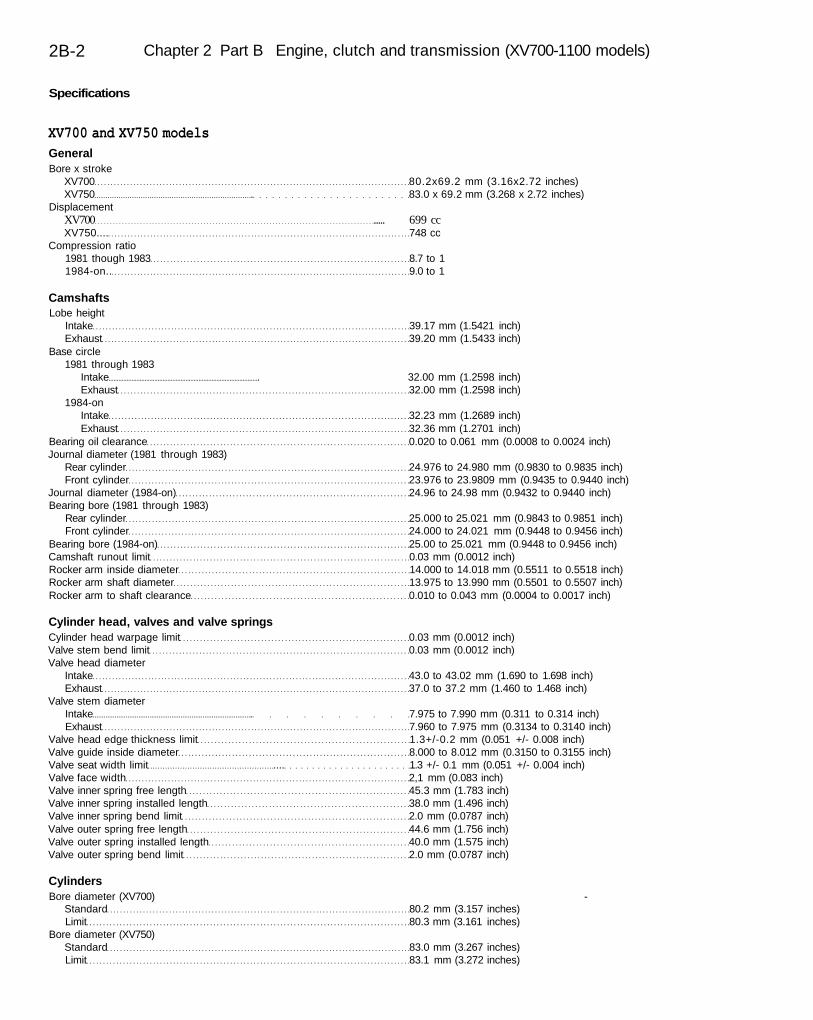
XV700 and XV750 modelsGeneralBore x stroke
XV700 80.2x69.2 mm (3.16x2.72 inches)XV750 . 83.0 x 69.2 mm (3.268 x 2.72 inches)
DisplacementXV700 ..... 699 ccXV750.... 748 cc
Compression ratio1981 though 1983 8.7 to 11984-on.. 9.0 to 1
CamshaftsLobe height
Intake 39.17 mm (1.5421 inch)Exhaust 39.20 mm (1.5433 inch)
Base circle1981 through 1983
Intake . 32.00 mm (1.2598 inch)Exhaust 32.00 mm (1.2598 inch)
1984-onIntake 32.23 mm (1.2689 inch)Exhaust 32.36 mm (1.2701 inch)
Bearing oil clearance 0.020 to 0.061 mm (0.0008 to 0.0024 inch)Journal diameter (1981 through 1983)
Rear cylinder 24.976 to 24.980 mm (0.9830 to 0.9835 inch)Front cylinder 23.976 to 23.9809 mm (0.9435 to 0.9440 inch)
Journal diameter (1984-on) 24.96 to 24.98 mm (0.9432 to 0.9440 inch)Bearing bore (1981 through 1983)
Rear cylinder 25.000 to 25.021 mm (0.9843 to 0.9851 inch)Front cylinder 24.000 to 24.021 mm (0.9448 to 0.9456 inch)
Bearing bore (1984-on) 25.00 to 25.021 mm (0.9448 to 0.9456 inch)Camshaft runout limit 0.03 mm (0.0012 inch)Rocker arm inside diameter 14.000 to 14.018 mm (0.5511 to 0.5518 inch)Rocker arm shaft diameter 13.975 to 13.990 mm (0.5501 to 0.5507 inch)Rocker arm to shaft clearance 0.010 to 0.043 mm (0.0004 to 0.0017 inch)
Cylinder head, valves and valve springsCylinder head warpage limit 0.03 mm (0.0012 inch)Valve stem bend limit 0.03 mm (0.0012 inch)Valve head diameter
Intake 43.0 to 43.02 mm (1.690 to 1.698 inch)Exhaust 37.0 to 37.2 mm (1.460 to 1.468 inch)
Valve stem diameterIntake . 7.975 to 7.990 mm (0.311 to 0.314 inch)Exhaust 7.960 to 7.975 mm (0.3134 to 0.3140 inch)
Valve head edge thickness limit 1.3+/-0.2 mm (0.051 +/- 0.008 inch)Valve guide inside diameter 8.000 to 8.012 mm (0.3150 to 0.3155 inch)Valve seat width limit .... 1.3 +/- 0.1 mm (0.051 +/- 0.004 inch)Valve face width 2,1 mm (0.083 inch)Valve inner spring free length 45.3 mm (1.783 inch)Valve inner spring installed length 38.0 mm (1.496 inch)Valve inner spring bend limit 2.0 mm (0.0787 inch)Valve outer spring free length 44.6 mm (1.756 inch)Valve outer spring installed length 40.0 mm (1.575 inch)Valve outer spring bend limit 2.0 mm (0.0787 inch)
CylindersBore diameter (XV700) -
Standard 80.2 mm (3.157 inches)Limit 80.3 mm (3.161 inches)
Bore diameter (XV750)Standard 83.0 mm (3.267 inches)Limit 83.1 mm (3.272 inches)
Chapter 2 Part B Engine, clutch and transmission (XV700-1100 models) 2B-3
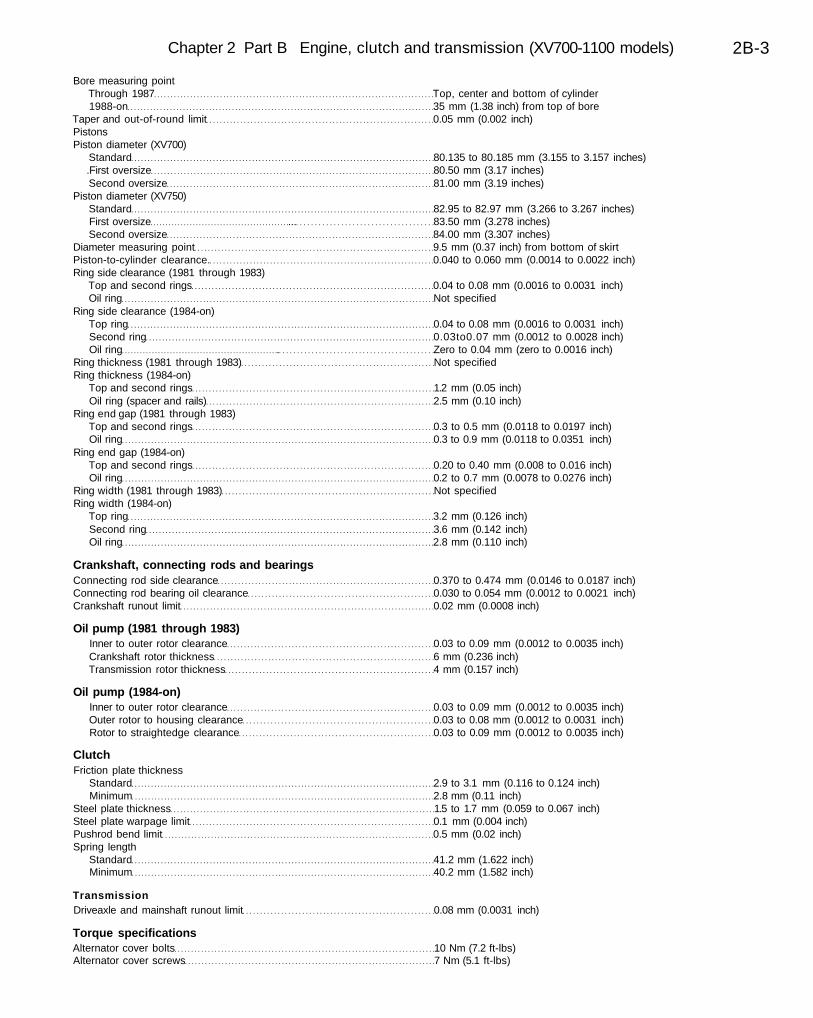
Bore measuring pointThrough 1987 Top, center and bottom of cylinder1988-on 35 mm (1.38 inch) from top of bore
Taper and out-of-round limit 0.05 mm (0.002 inch)PistonsPiston diameter (XV700)
Standard 80.135 to 80.185 mm (3.155 to 3.157 inches).First oversize 80.50 mm (3.17 inches)Second oversize 81.00 mm (3.19 inches)
Piston diameter (XV750)Standard 82.95 to 82.97 mm (3.266 to 3.267 inches)First oversize ... 83.50 mm (3.278 inches)Second oversize 84.00 mm (3.307 inches)
Diameter measuring point 9.5 mm (0.37 inch) from bottom of skirtPiston-to-cylinder clearance. 0.040 to 0.060 mm (0.0014 to 0.0022 inch)Ring side clearance (1981 through 1983)
Top and second rings 0.04 to 0.08 mm (0.0016 to 0.0031 inch)Oil ring Not specified
Ring side clearance (1984-on)Top ring 0.04 to 0.08 mm (0.0016 to 0.0031 inch)Second ring 0.03to0.07 mm (0.0012 to 0.0028 inch)Oil ring . Zero to 0.04 mm (zero to 0.0016 inch)
Ring thickness (1981 through 1983) Not specifiedRing thickness (1984-on)
Top and second rings 1.2 mm (0.05 inch)Oil ring (spacer and rails) 2.5 mm (0.10 inch)
Ring end gap (1981 through 1983)Top and second rings 0.3 to 0.5 mm (0.0118 to 0.0197 inch)Oil ring 0.3 to 0.9 mm (0.0118 to 0.0351 inch)
Ring end gap (1984-on)Top and second rings 0.20 to 0.40 mm (0.008 to 0.016 inch)Oil ring 0.2 to 0.7 mm (0.0078 to 0.0276 inch)
Ring width (1981 through 1983) Not specifiedRing width (1984-on)
Top ring 3.2 mm (0.126 inch)Second ring 3.6 mm (0.142 inch)Oil ring 2.8 mm (0.110 inch)
Crankshaft, connecting rods and bearingsConnecting rod side clearance 0.370 to 0.474 mm (0.0146 to 0.0187 inch)Connecting rod bearing oil clearance 0.030 to 0.054 mm (0.0012 to 0.0021 inch)Crankshaft runout limit 0.02 mm (0.0008 inch)
Oil pump (1981 through 1983)Inner to outer rotor clearance 0.03 to 0.09 mm (0.0012 to 0.0035 inch)Crankshaft rotor thickness 6 mm (0.236 inch)Transmission rotor thickness 4 mm (0.157 inch)
Oil pump (1984-on)Inner to outer rotor clearance 0.03 to 0.09 mm (0.0012 to 0.0035 inch)Outer rotor to housing clearance 0.03 to 0.08 mm (0.0012 to 0.0031 inch)Rotor to straightedge clearance 0.03 to 0.09 mm (0.0012 to 0.0035 inch)
ClutchFriction plate thickness
Standard 2.9 to 3.1 mm (0.116 to 0.124 inch)Minimum 2.8 mm (0.11 inch)
Steel plate thickness 1.5 to 1.7 mm (0.059 to 0.067 inch)Steel plate warpage limit 0.1 mm (0.004 inch)Pushrod bend limit 0.5 mm (0.02 inch)Spring length
Standard 41.2 mm (1.622 inch)Minimum 40.2 mm (1.582 inch)
TransmissionDriveaxle and mainshaft runout limit 0.08 mm (0.0031 inch)
Torque specificationsAlternator cover bolts 10 Nm (7.2 ft-lbs)Alternator cover screws 7 Nm (5.1 ft-lbs)
2B-4 Chapter 2 Part B Engine, clutch and transmission (XV700-1100 models)
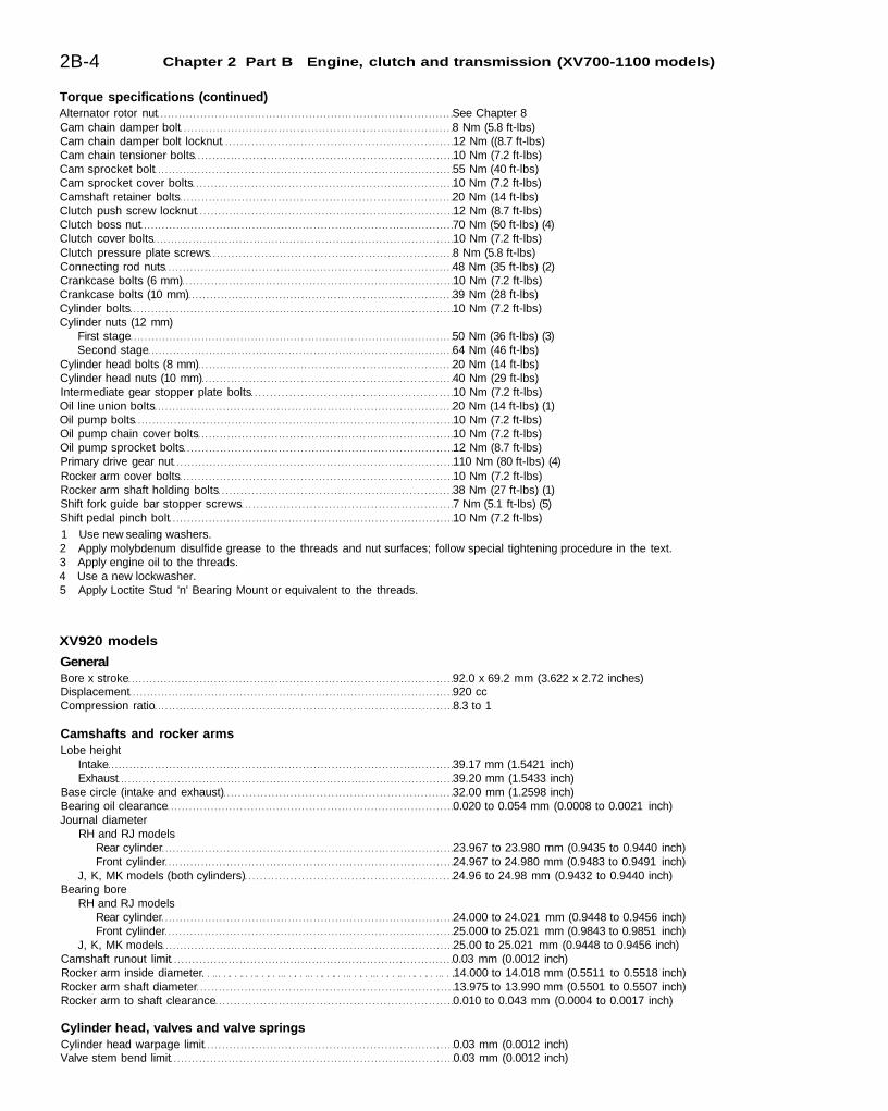
Torque specifications (continued)Alternator rotor nut See Chapter 8Cam chain damper bolt 8 Nm (5.8 ft-lbs)Cam chain damper bolt locknut 12 Nm ((8.7 ft-lbs)Cam chain tensioner bolts 10 Nm (7.2 ft-lbs)Cam sprocket bolt 55 Nm (40 ft-lbs)Cam sprocket cover bolts 10 Nm (7.2 ft-lbs)Camshaft retainer bolts 20 Nm (14 ft-lbs)Clutch push screw locknut 12 Nm (8.7 ft-lbs)Clutch boss nut 70 Nm (50 ft-lbs) (4)Clutch cover bolts 10 Nm (7.2 ft-lbs)Clutch pressure plate screws 8 Nm (5.8 ft-lbs)Connecting rod nuts 48 Nm (35 ft-lbs) (2)Crankcase bolts (6 mm) 10 Nm (7.2 ft-lbs)Crankcase bolts (10 mm) 39 Nm (28 ft-lbs)Cylinder bolts 10 Nm (7.2 ft-lbs)Cylinder nuts (12 mm)
First stage 50 Nm (36 ft-lbs) (3)Second stage 64 Nm (46 ft-lbs)
Cylinder head bolts (8 mm) 20 Nm (14 ft-lbs)Cylinder head nuts (10 mm) 40 Nm (29 ft-lbs)Intermediate gear stopper plate bolts 10 Nm (7.2 ft-lbs)Oil line union bolts 20 Nm (14 ft-lbs) (1)Oil pump bolts 10 Nm (7.2 ft-lbs)Oil pump chain cover bolts 10 Nm (7.2 ft-lbs)Oil pump sprocket bolts 12 Nm (8.7 ft-lbs)Primary drive gear nut 110 Nm (80 ft-lbs) (4)Rocker arm cover bolts 10 Nm (7.2 ft-lbs)Rocker arm shaft holding bolts 38 Nm (27 ft-lbs) (1)Shift fork guide bar stopper screws 7 Nm (5.1 ft-lbs) (5)Shift pedal pinch bolt 10 Nm (7.2 ft-lbs)1 Use new sealing washers.2 Apply molybdenum disulfide grease to the threads and nut surfaces; follow special tightening procedure in the text.3 Apply engine oil to the threads.4 Use a new lockwasher.5 Apply Loctite Stud 'n' Bearing Mount or equivalent to the threads.
XV920 models
GeneralBore x stroke 92.0 x 69.2 mm (3.622 x 2.72 inches)Displacement 920 ccCompression ratio 8.3 to 1
Camshafts and rocker armsLobe height
Intake 39.17 mm (1.5421 inch)Exhaust 39.20 mm (1.5433 inch)
Base circle (intake and exhaust) 32.00 mm (1.2598 inch)Bearing oil clearance 0.020 to 0.054 mm (0.0008 to 0.0021 inch)Journal diameter
RH and RJ modelsRear cylinder 23.967 to 23.980 mm (0.9435 to 0.9440 inch)Front cylinder 24.967 to 24.980 mm (0.9483 to 0.9491 inch)
J, K, MK models (both cylinders) 24.96 to 24.98 mm (0.9432 to 0.9440 inch)Bearing bore
RH and RJ modelsRear cylinder 24.000 to 24.021 mm (0.9448 to 0.9456 inch)Front cylinder 25.000 to 25.021 mm (0.9843 to 0.9851 inch)
J, K, MK models 25.00 to 25.021 mm (0.9448 to 0.9456 inch)Camshaft runout limit 0.03 mm (0.0012 inch)Rocker arm inside diameter 14.000 to 14.018 mm (0.5511 to 0.5518 inch)Rocker arm shaft diameter 13.975 to 13.990 mm (0.5501 to 0.5507 inch)Rocker arm to shaft clearance 0.010 to 0.043 mm (0.0004 to 0.0017 inch)
Cylinder head, valves and valve springsCylinder head warpage limit 0.03 mm (0.0012 inch)Valve stem bend limit 0.03 mm (0.0012 inch)
Chapter 2 Part B Engine, clutch and transmission (XV700-1100 models) 2B-5
Valve head diameterRH models
Intake 43.0 to 43.02 mm (1.690 to 1.698 inch)Exhaust 37.0 to 37.2 mm (1.460 to 1.468 inch)
J, K, MK modelsIntake 47.0 to 47.2 mm (1.850 to 1.858 inch)Exhaust 39.0 to 39.2 mm (1.540 to 1.548 inch)
Valve stem diameterIntake 7.975 to 7.990 mm (0.311 to 0.314 inch)Exhaust 7.960 to 7.975 mm (0.3134 to 0.3140 inch)
Valve head edge thickness limit 1.3 +/-0.2 mm (0.051 +/- 0.008 inch)Valve guide inside diameter 8.000 to 8.012 mm (0.3150 to 0.3155 inch)Valve seat width limit 1.3 +/- 0.1 mm (0.051 +/- 0.004 inch)Valve face width 2.1 mm (0.083 inch)Valve inner spring free length 45.3 mm (1.783 inch)Valve inner spring installed length 38.0 mm (1.496 inch)Valve inner spring bend limit 2.0 mm (0.0787 inch)Valve outer spring free length 44.6 mm (1.756 inch)Valve outer spring installed length 40.0 mm (1.575 inch)Valve outer spring bend limit 2.0 mm (0.0787 inch)
CylindersBore diameter
Standard 92.0 mm (3.622 inches)Limit Not specified
Bore measuring point Top, center and bottom of cylinderTaper and out-of-round limit 0.05 mm (0.002 inch)PistonsPiston diameter
Standard 92.0 mm (3.622 inches)First oversize 93.25 mm (3.67 inches)Second oversize 93.50 mm (3.68 inche.s)
Diameter measuring point 14.6 mm (0.575 inch) from bottom of skirtPiston-to-cylinder clearance 0.045 to 0.065 mm (0.0018 to 0.0026 inch)Ring side clearance (J, K, MK models)
Top ring 0.04 to 0.08 mm (0.0016 to 0.0031 inch)Second ring 0.03 to 0.07 mm (0.0012 to 0.0028 inch)Oil ring Zero
Ring thickness (J, K, MK models)Top ring 1.5 mm (0.06 inch)Second ring 2.0 mm (0.08 inch)Oil ring (spacer and rails) 4.0 mm (0.16 inch)
Ring end gap (J, K, MK models)Top and second rings 0.20 to 0.40 mm (0.008 to 0.016 inch)Oil ring 0.3 to 0.6 mm (0.0012 to 0.0024 inch)
Ring width (J, K, MK models)Top ring 3.8 mm (0.15 inch)Second ring 4.0 mm (0.16 inch)Oil ring 3.9 mm (0.15 inch)
Crankshaft, connecting rods and bearingsConnecting rod side clearance 0.370 to 0.474 mm (0.0146 to 0.0187 inch)Connecting rod bearing oil clearance 0.030 to 0.054 mm (0.0012 to 0.0021 inch)Crankshaft runout limit . . 0.02 mm (0.0008 inch)
Oil pumpInner to outer rotor clearance 0.03 to 0.09 mm (0.0012 to 0.0035 inch)Crankshaft rotor thickness 6 mm (0.236 inch)Transmission rotor thickness 4 mm (0.157 inch)
ClutchFriction plate thickness
Standard 2.9 to 3.1 mm (0.116 to 0.124 inch)Minimum 2.8 mm (0.11 inch)
Steel plate thickness 1.5 to 1.7 mm (0.059 to 0.067 inch)Steel plate warpage limit 0.1 mm (0.004 inch)Pushrod bend limit 0.5 mm (0.02 inch)Spring length
Standard 41.2 mm (1.622 inch)Minimum 40.2 mm (1.582 inch)
2B-6 Chapter 2 Part B Engine, clutch and transmission (XV700-1100 models)
TransmissionDriveaxle and mainshaft runout limit 0.08 mm (0.0031 inch)
Torque specificationsAlternator cover bolts 10 Nm (7.2 ft-lbs)Alternator cover screws 7 Nm (5.1 ft-lbs)Alternator rotor nut , See Chapter 8Cam chain damper bolt 8 Nm (5.8 ft-lbs)Cam chain damper bolt locknut 12 Nm ((8.7 ft-lbs)Cam chain tensioner bolts 10 Nm (7.2 ft-lbs)Cam sprocket bolt 55 Nm (40 ft-lbs)Cam sprocket cover bolts 10 Nm (7.2 ft-lbs)Camshaft retainer bolts 20 Nm (14 ft-lbs)Clutch push screw locknut 12 Nm (8.7 ft-lbs)Clutch boss nut 70 Nm (50 ft-lbs) (4)Clutch cover bolts 10 Nm (7.2 ft-lbs)Clutch pressure plate screws . 8 Nm (5.8 ft-lbs)Connecting rod nuts 48 Nm (35 ft-lbs) (2)Crankcase bolts (6 mm) 10 Nm (7.2 ft-lbs)Crankcase bolts (10 mm) 39 Nm (28 ft-lbs)Cylinder bolts 10 Nm (7.2 ft-lbs)Cylinder head 12 mm nuts
First stage 50 Nm (36 ft-lbs) (3)Second stage 64 Nm (46 ft-lbs)
Cylinder head bolts (8 mm) 20 Nm (14 ft-lbs)Cylinder head nuts (10 mm) 40 Nm (29 ft-lbs)Intermediate gear stopper plate bolts 10 Nm (7.2 ft-lbs)Oil line union bolts 20 Nm (14 ft-lbs) (1)Oil pump bolts 10 Nm (7.2 ft-lbs)Oil pump chain cover bolts ... 10 Nm (7.2 ft-lbs)Oil pump sprocket bolts 12 Nm (8.7 ft-lbs)Primary drive gear nut 110 Nm (80 ft-lbs) (4)Rocker arm cover bolts 10 Nm (7.2 ft-lbs)Rocker arm shaft holding bolts 38 Nm (27 ft-lbs) (1)Shift fork guide bar stopper screws 7 Nm (5.1 ft-lbs) (5)Shift pedal pinch bolt 10 Nm (7.2 ft-lbs)
7 Use new sealing washers.2 Apply molybdenum disulfide grease to the threads and nut surfaces; follow special tightening procedure in the text.3 Apply engine oil to the threads.4 Use a new lockwasher.5 Apply Loctite Stud 'n' Bearing Mount or equivalent to the threads.
XV1000 models
GeneralBore x stroke 95.0 x 69.2 mm (3.74 x 2.72 inches)Displacement 981 ccCompression ratio 8.3 to 1
CamshaftsLobe height
Intake 39.17 mm (1.5421 inch)Exhaust.... 39.20 mm (1.5433 inch)
Base circleIntake 32.17 mm (1.2665 inch)Exhaust 32.27 mm (1.2705 inch)
Bearing oil clearance 0.020 to 0.061 mm (0.0008 to 0.0024 inch)Journal diameter 24.96 to 24.98 mm (0.9432 to 0.9440 inch)Bearing bore . 25.00 to 25.021 mm (0.9448 to 0.9456 inch)Camshaft runout limit 0.03 mm (0.0012 inch)Rocker arm inside diameter 14.000 to 14.018 mm (0.5511 to 0.5518 inch)Rocker arm shaft diameter 13.975 to 13.990 mm (0.5501 to 0.5507 inch)Rocker arm to shaft clearance 0.010 to 0.043 mm (0.0004 to 0.0017 inch)
Cylinder head, valves and valve springsCylinder head warpage limit 0.03 mm (0.0012 inch)Valve stem bend limit 0.03 mm (0.0012 inch)Valve head diameter
Intake 47.0 to 47.02 mm (1.850 to 1.858 inch)Exhaust 39.0 to 39.2 mm (1.540 to 1.562 inch)
Chapter 2 Part B Engine, clutch and transmission (XV700-1100 models) 2B-7
Valve stem diameterIntake 7.975 to 7.990 mm (0.311 to 0.314 inch)Exhaust . 7.960 to 7.975 mm (0.3134 to 0.3140 inch)
Valve head edge thickness limit 1.3 +/- 0.2 mm (0.051 +/- 0.008 inch)Valve guide inside diameter 8.000 to 8.012 mm (0.3150 to 0.3155 inch)Valve seat width limit 1.3 +/- 0.1 mm (0.051 +/- 0.004 inch)Valve face width 2.1 mm (0.083 inch)Valve inner spring free length 45.3 mm (1.783 inch)Valve inner spring installed length 38.0 mm (1.496 inch)Valve inner spring bend limit 2.0 mm (0.0787 inch)Valve outer spring free length 44.6 mm (1.756 inch)Valve outer spring installed length 40.0 mm (1.575 inch)Valve outer spring bend limit 2.0 mm (0.0787 inch)
CylindersBore diameter
Standard . 95.0 mm (3.740 inches)Limit 95.1 mm (3.744 inches)
Bore measuring point Top, center and bottom of cylinderTaper and out-of-round limit 0.05 mm (0.002 inch)PistonsPiston diameter
Standard 94.945 to 94.965 mm (3.738 to 3.739 inches)First oversize 95.50 mm (3.76 inches)Second oversize 96.00 mm (3.78 inches)
Diameter measuring point 14.6 mm (0.575 inch) from bottom of skirtPiston-to-cylinder clearance.. 0.045 to 0.065 mm (0.0018 to 0.0026 inch)Ring side clearance
Top ring 0.04 to 0.08 mm (0.0016 to 0.0031 inch)Second ring 0.03 to 0.07 mm (0.0012 to 0.0028 inch)Oil ring Zero
Ring thicknessTop and second rings 1.5 mm (0.06 inch)Oil ring (spacer and rails) 3.8 mm (0.15 inch)
Ring end gapTop and second rings 0.30 to 0.50 mm (0.012 to 0.020 inch)Oil ring 0.3 to 0.9 mm (0.012 to 0.035 inch)
Ring widthTop ring 3.8 mm (0.15 inch)Second ring 4.0 mm (0.16 inch)Oil ring 3.9 mm (0.153 inch)
Crankshaft, connecting rods and bearingsConnecting rod side clearance... 0.370 to 0.474 mm (0.0146 to 0.0187 inch)Connecting rod bearing oil clearance 0.030 to 0.054 mm (0.0012 to 0.0021 inch)Crankshaft runout limit 0.02 mm (0.0008 inch)
Oil pumpInner to outer rotor clearance 0.03 to 0.09 mm (0.0012 to 0.0035 inch)Outer rotor to housing clearance 0.03 to 0.08 mm (0.0012 to 0.0031 inch)Rotor to straightedge clearance 0.03 to 0.09 mm (0.0012 to 0.0035 inch)
ClutchFriction plate thickness
Standard 2.9 to 3.1 mm (0.116 to 0.124 inch)Minimum 2.8 mm (0.11 inch)
Steel plate thickness 1.5 to 1.7 mm (0.059 to 0.067 inch)Steel plate warpage limit 0.1 mm (0.004 inch)Pushrod bend limit 0.5 mm (0.02 inch)Spring length
Standard 41.2 mm (1.622 inch)Minimum 40.2 mm (1.582 inch)
TransmissionDriveaxle and mainshaft runout limit 0.08 mm (0.0031 inch)
Torque specificationsAlternator cover bolts 10 Nm (7.2 ft-lbs)Alternator cover screws 7 Nm (5.1 ft-lbs)Alternator rotor nut See Chapter 8
2B-8 Chapter 2 Part B Engine, clutch and transmission (XV700-1100 models)
Torque specifications (continued)Cam chain damper bolt 8 Nm (5.8 ft-lbs)'Cam chain damper bolt locknut 12 Nm ((8.7 ft-lbs)Cam chain tensioner bolts 10 Nm (7.2 ft-lbs)Cam sprocket bolt 55 Nm (40 ft-lbs)Cam sprocket cover bolts 10 Nm (7.2 ft-lbs)Camshaft bushing bolts 20 Nm (14 ft-lbs)Clutch push screw locknut 12 Nm (8.7 ft-lbs)Clutch boss nut 70 Nm (50 ft-lbs) (4)Clutch cover bolts.... 10 Nm (7.2 ft-lbs)Clutch pressure plate screws 8 Nm (5.8 ft-lbs)Connecting rod nuts 48 Nm (35 ft-lbs) (2)Crankcase bolts (6 mm).... 10 Nm (7.2 ft-lbs)Crankcase bolts (10 mm) 39 Nm (28 ft-lbs)Cylinder bolts 10 Nm (7.2 ft-lbs)Cylinder head bolts (8 mm) 20 Nm (14 ft-lbs)Cylinder head nuts (10 mm) 35 Nm (25 ft-lbs)Cylinder head nuts (12 mm) 50 Nm (36 ft-lbs)Intermediate gear stopper plate bolts 10 Nm (7.2 ft-lbs)Oil line union bolts 20 Nm (14 ft-lbs) (1)Oil pump bolts 10 Nm (7.2 ft-lbs)Oil pump chain cover bolts 10 Nm (7.2 ft-lbs)Oil pump sprocket bolts 12 Nm (8.7 ft-lbs)Primary drive gear nut 110 Nm (80 ft-lbs) (4)Rocker arm cover bolts 10 Nm (7.2 ft-lbs)Rocker arm shaft holding bolts 38 Nm (27 ft-lbs) (1)Shift fork guide bar stopper screws 7 Nm (5.1 ft-lbs) (5)Shift pedal pinch bolt 10 Nm (7.2 ft-lbs)1 Use new sealing washers.2 Apply molybdenum disulfide grease to the threads and nut surfaces; follow special tightening procedure in the text.3 Apply engine oil to the threads.4 Use a new lockwasher.5 Apply Loctite Stud 'n' Bearing Mount or equivalent to the threads.
XV1100 models
GeneralBore x stroke 95.0 x 75.0 mm (3.74 x 2.95 inches)Displacement 1063ccCompression ratio 8.3 to 1
CamshaftsLobe height
Intake 39.17 mm (1.5421 inch)Exhaust 39.20 mm (1.5433 inch)
Base circleintake 32.17 mm (1.2665 inch)Exhaust 32.27 mm (1.2705 inch)
Bearing oil clearance 0.020 to 0.061 mm (0.0008 to 0.0024 inch)Journal diameter 24.96 to 24.98 mm (0.9432 to 0.9440 inch)Bearing bore 25.00 to 25.021 mm (0.9483 to 0.9451 inch)Camshaft runout limit 0.03 mm (0.0012 inch)Rocker arm inside diameter 14.000 to 14.018 mm (0.5511 to 0.5518 inch)Rocker arm shaft diameter 13.975 to 13.990 mm (0.5501 to 0.5507 inch)Rocker arm to shaft clearance 0.010 to 0.043 mm (0.0004 to 0.0017 inch)
Cylinder head, valves and valve springsCylinder head warpage limit 0.03 mm (0.0012 inch)Valve stem bend limit 0.03 mm (0.0012 inch)Valve head diameter
Intake 47.0 to 47.02 mm (1.850 to 1.858 inch)Exhaust 39.0 to 39.2 mm (1.540 to 1.562 inch)
Valve stem diameterIntake 7.975 to 7.990 mm (0.311 to 0.314 inch)Exhaust 7.960 to 7.975 mm (0.3134 to 0.3140 inch)
Valve head edge thickness limit 1.3 +/- 0.2 mm (0.051 +/- 0.008 inch)Valve guide inside diameter 8.000 to 8.012 mm (0.3150 to 0.3155 inch)Valve seat width limit 1.3 +/- 0.1 mm (0.051 +/- 0.004 inch)
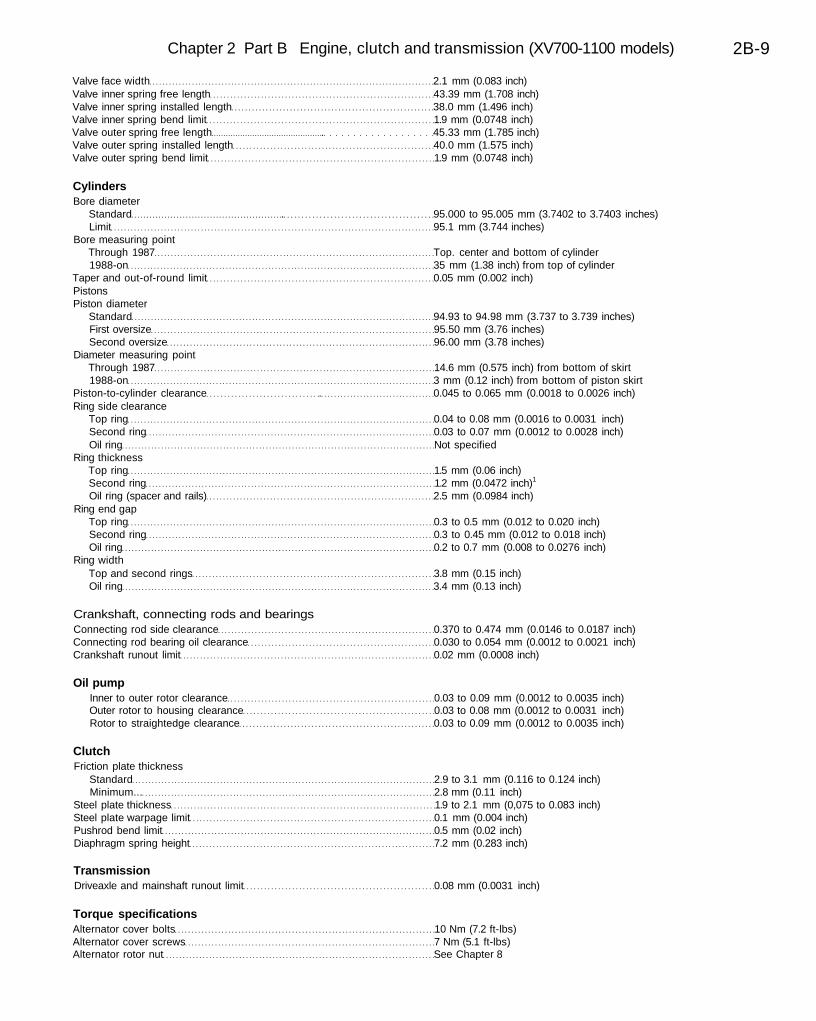
Chapter 2 Part B Engine, clutch and transmission (XV700-1100 models) 2B-9
Valve face width 2.1 mm (0.083 inch)Valve inner spring free length 43.39 mm (1.708 inch)Valve inner spring installed length 38.0 mm (1.496 inch)Valve inner spring bend limit 1.9 mm (0.0748 inch)Valve outer spring free length . 45.33 mm (1.785 inch)Valve outer spring installed length 40.0 mm (1.575 inch)Valve outer spring bend limit 1.9 mm (0.0748 inch)
CylindersBore diameter
Standard . 95.000 to 95.005 mm (3.7402 to 3.7403 inches)Limit 95.1 mm (3.744 inches)
Bore measuring pointThrough 1987 Top. center and bottom of cylinder1988-on 35 mm (1.38 inch) from top of cylinder
Taper and out-of-round limit 0.05 mm (0.002 inch)PistonsPiston diameter
Standard 94.93 to 94.98 mm (3.737 to 3.739 inches)First oversize 95.50 mm (3.76 inches)Second oversize 96.00 mm (3.78 inches)
Diameter measuring pointThrough 1987 14.6 mm (0.575 inch) from bottom of skirt1988-on 3 mm (0.12 inch) from bottom of piston skirt
Piston-to-cylinder clearance . 0.045 to 0.065 mm (0.0018 to 0.0026 inch)Ring side clearance
Top ring 0.04 to 0.08 mm (0.0016 to 0.0031 inch)Second ring 0.03 to 0.07 mm (0.0012 to 0.0028 inch)Oil ring Not specified
Ring thicknessTop ring 1.5 mm (0.06 inch)Second ring 1.2 mm (0.0472 inch)1
Oil ring (spacer and rails) 2.5 mm (0.0984 inch)Ring end gap
Top ring 0.3 to 0.5 mm (0.012 to 0.020 inch)Second ring 0.3 to 0.45 mm (0.012 to 0.018 inch)Oil ring 0.2 to 0.7 mm (0.008 to 0.0276 inch)
Ring widthTop and second rings 3.8 mm (0.15 inch)Oil ring 3.4 mm (0.13 inch)
Crankshaft, connecting rods and bearingsConnecting rod side clearance 0.370 to 0.474 mm (0.0146 to 0.0187 inch)Connecting rod bearing oil clearance 0.030 to 0.054 mm (0.0012 to 0.0021 inch)Crankshaft runout limit 0.02 mm (0.0008 inch)
Oil pumpInner to outer rotor clearance 0.03 to 0.09 mm (0.0012 to 0.0035 inch)Outer rotor to housing clearance 0.03 to 0.08 mm (0.0012 to 0.0031 inch)Rotor to straightedge clearance 0.03 to 0.09 mm (0.0012 to 0.0035 inch)
ClutchFriction plate thickness
Standard 2.9 to 3.1 mm (0.116 to 0.124 inch)Minimum... 2.8 mm (0.11 inch)
Steel plate thickness 1.9 to 2.1 mm (0,075 to 0.083 inch)Steel plate warpage limit 0.1 mm (0.004 inch)Pushrod bend limit 0.5 mm (0.02 inch)Diaphragm spring height 7.2 mm (0.283 inch)
TransmissionDriveaxle and mainshaft runout limit 0.08 mm (0.0031 inch)
Torque specificationsAlternator cover bolts 10 Nm (7.2 ft-lbs)Alternator cover screws 7 Nm (5.1 ft-lbs)Alternator rotor nut See Chapter 8
2B-10 Chapter 2 Part B Engine, clutch and transmission (XV700-1100 models)
Torque specifications (continued)Cam chain damper bolt 8 Nm (5.8 ft-lbs)Cam chain clamper bolt locknut 12 Nm (8.7 ft-lbs)Cam chain tensioner bolts 10 Nm (7.2 ft-lbs)Cam sprocket bolt 55 Nm (40 ft-lbs)Cam sprocket cover bolts 10 Nm (7.2 ft-lbs)Camshaft retainer bolts 20 Nm (14 ft-lbs)Clutch push screw locknut 12 Nm (8.7 ft-lbs)Clutch boss nut 70 Nm (50 ft-lbs) (4)Clutch cover bolts 10 Nm (7.2 ft-lbs)Clutch pressure plate screws 8 Nm (5.8 ft-lbs)Connecting rod nuts 48 Nm (35 ft-lbs) (2)Crankcase bolts (6 mm) 10 Nm (7.2 ft-lbs)Crankcase bolts (10 mm) 39 Nm (28 ft-lbs)Cylinder bolts 10 Nm (7.2 ft-lbs)Cylinder head bolts (8 mm) 20 Nm (14 ft-lbs)Cylinder head nuts (10 mm) 35 Nm (25 ft-lbs)Cylinder head nuts (12 mm) 50 Nm (36 ft-lbs)Intermediate gear stopper plate bolts 10 Nm (7.2 ft-lbs)Oil line union bolts 20 Nm (14 ft-lbs) (1)Oil pump bolts 10 Nm (7.2 ft-lbs)Oil pump chain cover bolts 10 Nm (7.2 ft-lbs)Oil pump sprocket bolts 12 Nm (8.7 ft-lbs)Primary drive gear nut 110 Nm (80 ft-lbs) (4)Rocker arm cover bolts 10 Nm (7.2 ft-lbs)Rocker arm shaft holding bolts 38 Nm (27 ft-lbs) (1)Shift fork guide bar stopper screws 7 Nm (5.1 ft-lbs) (5)Shift pedal pinch bolt 10 Nm (7.2 ft-lbs)
1 Use new sealing washers.2 Apply molybdenum disulfide grease to the threads and nut surfaces; follow special tightening procedure in the text.3 Apply engine oil to the threads.4 Use a new lockwasher.5 Apply Loctite Stud 'n' Bearing Mount or equivalent to the threads.
1 General information
Note: Some of the procedures in this Chapter are listed as applying to1981 through 1983 models. If you're working on a 1984 or 1985 TR1model, use the 1981 through 1983 procedures.
The engine/transmission unit is an air-cooled V-twin. The valvesare operated by overhead camshafts which are chain driven off thecrankshaft. The engine/transmission assembly is constructed fromaluminum alloy. The crankcase is divided vertically.
The crankcase incorporates a wet sump, pressure-fed lubricationsystem which uses a chain-driven oil pump and an oil filter mounted inthe right-hand side of the crankcase.
Power from the crankshaft is routed to the transmission via theclutch, which is of the wet multi-plate type and is gear-driven off thecrankshaft. The transmission is a five-speed, constant-mesh unit.
2 Operations possible with the engine in the frame
The components and assemblies listed below can be removed withouthaving to remove the engine from the frame. If, however, a number ofareas require attention at the same time, removal of the engine is
recommended.Starter motorAlternatorOil pumpStarter clutchCam sprocketsClutch and primary drive gearExternal shift linkage
3 Operations requiring engine removal
It is necessary to remove the engine/transmission assembly from theframe to gain access to the following components:
Cylinder heads, rocker arms and camshaftsCylinders and pistonsCam chains and intermediate gears
The crankcase halves must be separated to gain access to thefollowing components:
Crankshaft, connecting rods and bearingsTransmission shaftsShift cam and forksOil pressure relief valve
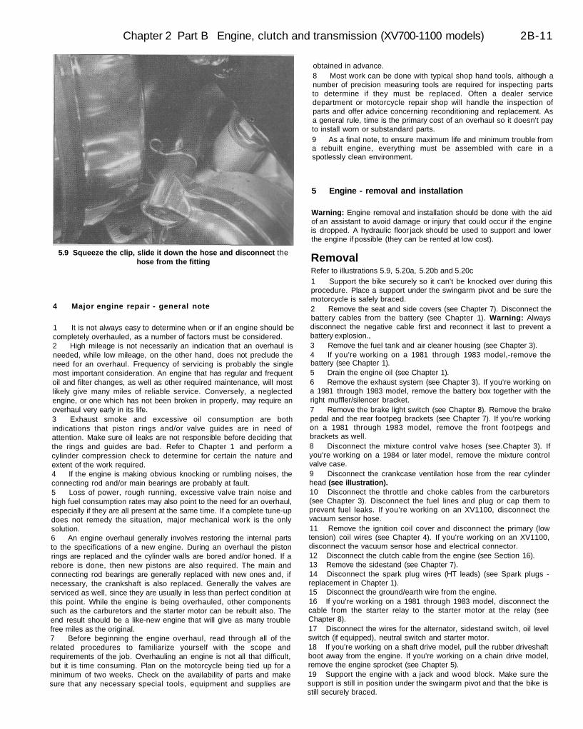
Chapter 2 Part B Engine, clutch and transmission (XV700-1100 models) 2B-11
5.9 Squeeze the clip, slide it down the hose and disconnect thehose from the fitting
4 Major engine repair - general note
1 It is not always easy to determine when or if an engine should becompletely overhauled, as a number of factors must be considered.2 High mileage is not necessarily an indication that an overhaul isneeded, while low mileage, on the other hand, does not preclude theneed for an overhaul. Frequency of servicing is probably the singlemost important consideration. An engine that has regular and frequentoil and filter changes, as well as other required maintenance, will mostlikely give many miles of reliable service. Conversely, a neglectedengine, or one which has not been broken in properly, may require anoverhaul very early in its life.3 Exhaust smoke and excessive oil consumption are bothindications that piston rings and/or valve guides are in need ofattention. Make sure oil leaks are not responsible before deciding thatthe rings and guides are bad. Refer to Chapter 1 and perform acylinder compression check to determine for certain the nature andextent of the work required.4 If the engine is making obvious knocking or rumbling noises, theconnecting rod and/or main bearings are probably at fault.5 Loss of power, rough running, excessive valve train noise andhigh fuel consumption rates may also point to the need for an overhaul,especially if they are all present at the same time. If a complete tune-updoes not remedy the situation, major mechanical work is the onlysolution.6 An engine overhaul generally involves restoring the internal partsto the specifications of a new engine. During an overhaul the pistonrings are replaced and the cylinder walls are bored and/or honed. If arebore is done, then new pistons are also required. The main andconnecting rod bearings are generally replaced with new ones and, ifnecessary, the crankshaft is also replaced. Generally the valves areserviced as well, since they are usually in less than perfect condition atthis point. While the engine is being overhauled, other componentssuch as the carburetors and the starter motor can be rebuilt also. Theend result should be a like-new engine that will give as many troublefree miles as the original.7 Before beginning the engine overhaul, read through all of therelated procedures to familiarize yourself with the scope andrequirements of the job. Overhauling an engine is not all that difficult,but it is time consuming. Plan on the motorcycle being tied up for aminimum of two weeks. Check on the availability of parts and makesure that any necessary special tools, equipment and supplies are
obtained in advance.8 Most work can be done with typical shop hand tools, although anumber of precision measuring tools are required for inspecting partsto determine if they must be replaced. Often a dealer servicedepartment or motorcycle repair shop will handle the inspection ofparts and offer advice concerning reconditioning and replacement. Asa general rule, time is the primary cost of an overhaul so it doesn't payto install worn or substandard parts.9 As a final note, to ensure maximum life and minimum trouble froma rebuilt engine, everything must be assembled with care in aspotlessly clean environment.
5 Engine - removal and installation
Warning: Engine removal and installation should be done with the aidof an assistant to avoid damage or injury that could occur if the engineis dropped. A hydraulic floor jack should be used to support and lowerthe engine if possible (they can be rented at low cost).
RemovalRefer to illustrations 5.9, 5.20a, 5.20b and 5.20c1 Support the bike securely so it can't be knocked over during thisprocedure. Place a support under the swingarm pivot and be sure themotorcycle is safely braced.2 Remove the seat and side covers (see Chapter 7). Disconnect thebattery cables from the battery (see Chapter 1). Warning: Alwaysdisconnect the negative cable first and reconnect it last to prevent abattery explosion.,3 Remove the fuel tank and air cleaner housing (see Chapter 3).4 If you're working on a 1981 through 1983 model,-remove thebattery (see Chapter 1).5 Drain the engine oil (see Chapter 1).6 Remove the exhaust system (see Chapter 3). If you're working ona 1981 through 1983 model, remove the battery box together with theright muffler/silencer bracket.7 Remove the brake light switch (see Chapter 8). Remove the brakepedal and the rear footpeg brackets (see Chapter 7). If you're workingon a 1981 through 1983 model, remove the front footpegs andbrackets as well.8 Disconnect the mixture control valve hoses (see.Chapter 3). Ifyou're working on a 1984 or later model, remove the mixture controlvalve case.9 Disconnect the crankcase ventilation hose from the rear cylinderhead (see illustration).10 Disconnect the throttle and choke cables from the carburetors(see Chapter 3). Disconnect the fuel lines and plug or cap them toprevent fuel leaks. If you're working on an XV1100, disconnect thevacuum sensor hose.11 Remove the ignition coil cover and disconnect the primary (lowtension) coil wires (see Chapter 4). If you're working on an XV1100,disconnect the vacuum sensor hose and electrical connector.12 Disconnect the clutch cable from the engine (see Section 16).13 Remove the sidestand (see Chapter 7).14 Disconnect the spark plug wires (HT leads) (see Spark plugs -replacement in Chapter 1).15 Disconnect the ground/earth wire from the engine.16 If you're working on a 1981 through 1983 model, disconnect thecable from the starter relay to the starter motor at the relay (seeChapter 8).17 Disconnect the wires for the alternator, sidestand switch, oil levelswitch (if equipped), neutral switch and starter motor.18 If you're working on a shaft drive model, pull the rubber driveshaftboot away from the engine. If you're working on a chain drive model,remove the engine sprocket (see Chapter 5).19 Support the engine with a jack and wood block. Make sure thesupport is still in position under the swingarm pivot and that the bike isstill securely braced.

2B-12 Chapter 2 Part B Engine, clutch and transmission (XV700-1100 models)
5.20a Unbolt the front cylinder mountingbracket from the frame
5.20b Remove the rear cylinder bracket-to-frame bolts (arrow); there's one on each
side of the bike
5.20c Remove the mounting stud at therear on 1981 through 1983 models
5.23 Look through the viewing port toalign the driveshaft with the middle
driven gear
6.2a A selection of brushes is required forcleaning holes and passages in the
engine components
6.2b Type HPG-1 Plastigage is needed tocheck the connecting rod oil clearances
6.3 An engine stand can be made from short lengths of 2 x 4lumber and lag bolts or nails 7.1a If the engine has Type A tensioners, remove the Allen bolts
(arrows) and take the tensioner out
20 Remove the engine mounting bolts at the top of each cylinder(see illustrations). If you're working on a 1981 through 1983 model,remove the mounting stud at the rear of the engine (see illustration). Ifyou're working on a 1984 or later model, remove the mounting bolts atthe upper rear and lower rear of the engine.21 Make sure no wires or hoses are still attached to the engine
assembly. Warning: The engine is heavy and may cause injury if it falls.Be sure it's securely supported. Have an assistant help you steady theengine on the jack as you remove It.22 Slowly and carefully lower the engine assembly to the floor,disengaging the driveshaft (if equipped) as you do so. Guide the engineout from under the right side of the bike.
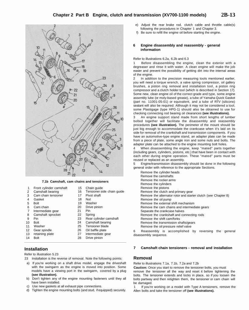
Chapter 2 Part B Engine, clutch and transmission (XV700-1100 models) 2B-13
7.1b Camshaft, cam chains and tensioners
123456789
1011121314
Front cylinder camshaftCamshaft bearingCam chain tensionerGasketBoltCam chainIntermediate gearCamshaft sprocketPinBoltWasherGear spindleretaining plateBolt
1516171819202122232425262728
Chain guideTensioner side chain guidePivot shaftNutWasherDrive pinionPinSpringRear cylinder camshaftCamshaft bearingTensioner bladeOil baffle plateintermediate gearDrive pinion
InstallationRefer to illustration 5.2323 Installation is the reverse of removal. Note the following points:
a) If you're working on a shaft drive model, engage the driveshaftwith the swingarm as the engine is moved into position. Somemodels have a viewing port in the swingarm, covered by a plug(see illustration).
b) Don't tighten any of the engine mounting fasteners until they allhave been installed.
c) Use new gaskets at all exhaust pipe connections.d) Tighten the engine mounting bolts (and stud, if equipped) securely.
e) Adjust the rear brake rod, clutch cable and throttle cable(s)following the procedures in Chapter 1 and Chapter 3.
f) Be sure to refill the engine oil before starting the engine.
6 Engine disassembly and reassembly - generalinformation
Refer to illustrations 6.2a, 6.2b and 6.31 Before disassembling the engine, clean the exterior with adegreaser and rinse it with water. A clean engine will make the jobeasier and prevent the possibility of getting dirt into the internal areasof the engine.2 In addition to the precision measuring tools mentioned earlier,you will need a torque wrench, a valve spring compressor, oil gallerybrushes, a piston ring removal and installation tool, a piston ringcompressor and a clutch holder tool (which is described in Section 17).Some new, clean engine oil of the correct grade and type, some engineassembly lube (or moly-based grease), a tube of Yamaha Quick Gasket(part no. 11001-05-01) or equivalent, and a tube of RTV (silicone)sealant will also be required. Although it may not be considered a tool,some Plastigage (type HPG-1) should also be obtained to use forchecking connecting rod bearing oil clearances (see illustrations).3 An engine support stand made from short lengths of lumberbolted together will facilitate the disassembly and reassemblyprocedures (see illustration). The perimeter of the mount should bejust big enough to accommodate the crankcase when it's laid on itsside for removal of the crankshaft and transmission components. If youhave an automotive-type engine stand, an adapter plate can be madefrom a piece of plate, some angle iron and some nuts and bolts. Theadapter plate can be attached to the engine mounting bolt holes.4 When disassembling the engine, keep "mated" parts together(including gears, cylinders, pistons, etc.) that have been in contact witheach other during engine operation. These "mated" parts must bereused or replaced as an assembly.5 Engine/transmission disassembly should be done in the followinggeneral order with reference to the appropriate Sections.
Remove the cylinder headsRemove the camshaftsRemove the rocker armsRemove the cylindersRemove the pistonsRemove the clutch and primary gearRemove the alternator rotor and starter clutch (see Chapter 8)Remove the oil pumpRemove the external shift mechanismRemove the cam chains and intermediate gearsSeparate the crankcase halvesRemove the crankshaft and connecting rodsRemove the shift cam/forksRemove the transmission shafts/gearsRemove the oil pressure relief valve
6 Reassembly is accomplished by reversing the generaldisassembly sequence.
7 Camshaft chain tensioners - removal and installation
RemovalRefer to illustrations 7.1a, 7.1b, 7.2a and 7.2bCaution: Once you start to remove the tensioner bolts, you mustremove the tensioner all the way and reset it before tightening thebolts. The tensioner extends and locks in place, so if you loosen thebolts partway and then retighten them, the tensioner or cam chain willbe damaged.1 If you're working on a model with Type A tensioners, remove theAllen bolts and take the tensioner off (see illustrations).
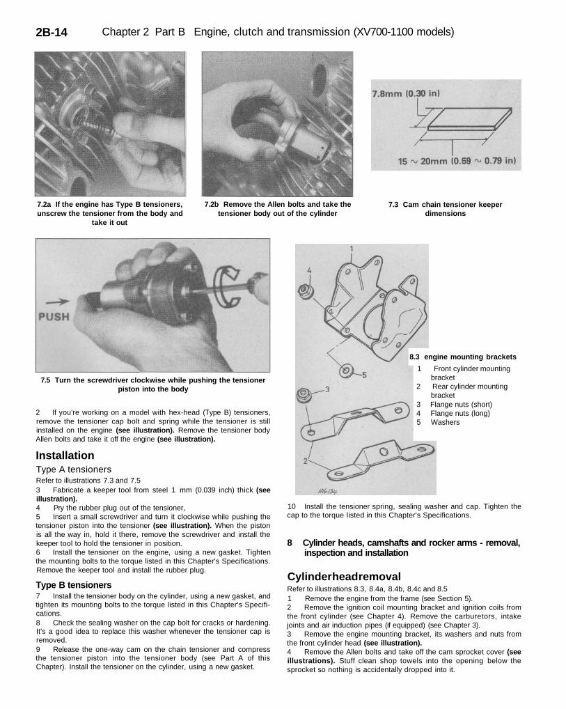
2B-14 Chapter 2 Part B Engine, clutch and transmission (XV700-1100 models)
7.2a If the engine has Type B tensioners,unscrew the tensioner from the body and
take it out
7.2b Remove the Allen bolts and take thetensioner body out of the cylinder
7.3 Cam chain tensioner keeperdimensions
7.5 Turn the screwdriver clockwise while pushing the tensionerpiston into the body
8.3 engine mounting brackets
1 Front cylinder mountingbracket
2 Rear cylinder mountingbracket
3 Flange nuts (short)4 Flange nuts (long)5 Washers
2 If you're working on a model with hex-head (Type B) tensioners,remove the tensioner cap bolt and spring while the tensioner is stillinstalled on the engine (see illustration). Remove the tensioner bodyAllen bolts and take it off the engine (see illustration).
InstallationType A tensionersRefer to illustrations 7.3 and 7.53 Fabricate a keeper tool from steel 1 mm (0.039 inch) thick (seeillustration).4 Pry the rubber plug out of the tensioner,5 Insert a small screwdriver and turn it clockwise while pushing thetensioner piston into the tensioner (see illustration). When the pistonis all the way in, hold it there, remove the screwdriver and install thekeeper tool to hold the tensioner in position.6 Install the tensioner on the engine, using a new gasket. Tightenthe mounting bolts to the torque listed in this Chapter's Specifications.Remove the keeper tool and install the rubber plug.
Type B tensioners7 Install the tensioner body on the cylinder, using a new gasket, andtighten its mounting bolts to the torque listed in this Chapter's Specifi-cations.8 Check the sealing washer on the cap bolt for cracks or hardening.It's a good idea to replace this washer whenever the tensioner cap isremoved.9 Release the one-way cam on the chain tensioner and compressthe tensioner piston into the tensioner body (see Part A of thisChapter). Install the tensioner on the cylinder, using a new gasket.
10 Install the tensioner spring, sealing washer and cap. Tighten thecap to the torque listed in this Chapter's Specifications.
8 Cylinder heads, camshafts and rocker arms - removal,inspection and installation
Cylinder head removalRefer to illustrations 8.3, 8.4a, 8.4b, 8.4c and 8.51 Remove the engine from the frame (see Section 5).2 Remove the ignition coil mounting bracket and ignition coils fromthe front cylinder (see Chapter 4). Remove the carburetors, intakejoints and air induction pipes (if equipped) (see Chapter 3).3 Remove the engine mounting bracket, its washers and nuts fromthe front cylinder head (see illustration).4 Remove the Allen bolts and take off the cam sprocket cover (seeillustrations). Stuff clean shop towels into the opening below thesprocket so nothing is accidentally dropped into it.
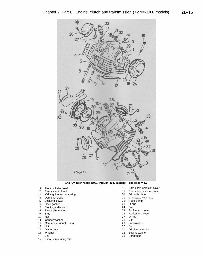
Chapter 2 Part B Engine, clutch and transmission (XV700-1100 models) 2B-15
8.4a Cylinder heads (1981 through 1983 models) - exploded view
123456789
1011121314151617
Front cylinder headRear cylinder headValve guide and snap-ringDamping blockLocating dowelHead gasketFront cylinder studRear cylinder studStudNutCopper washerCam chain tunnel O-ringNutDomed nutWasherBoltExhaust mounting stud
18192021222324252627282930313233
Cam chain sprocket coverCam chain sprocket coverOil baffle plateCrankcase vent hoseHose clampO-ringBoltRocker arm coverRocker arm coverO-ringBoltLockwasherBoltOil pipe union boltSealing washerSpark plug
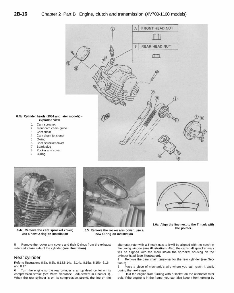
2B-16 Chapter 2 Part B Engine, clutch and transmission (XV700-1100 models)
8.4b Cylinder heads (1984 and later models) -exploded view
123456789
Cam sprocketFront cam chain guideCam chainCam chain tensionerO-ringCam sprocket coverSpark plugRocker arm coverO-ring
8.4c Remove the cam sprocket cover;use a new O-ring on installation
8.5 Remove the rocker arm cover; use anew O-ring on installation
8.6a Align the line next to the T mark withthe pointer
5 Remove the rocker arm covers and their O-rings from the exhaustside and intake side of the cylinder (see illustration).
Rear cylinderReferto illustrations 8.6a, 8.6b, 8.13,8.14a, 8.14b, 8.15a, 8.15b, 8.16and 8.176 Turn the engine so the rear cylinder is at top dead center on itscompression stroke (see Valve clearance - adjustment in Chapter 1).When the rear cylinder is on its compression stroke, the line on the
alternator rotor with a T mark next to it will be aligned with the notch inthe timing window (see illustration). Also, the camshaft sprocket markwill be aligned with the mark inside the sprocket housing on thecylinder head (see illustration).7 Remove the cam chain tensioner for the rear cylinder (see Sec-tion 7).8 Place a piece of mechanic's wire where you can reach it easilyduring the next steps.9 Hold the engine from turning with a socket on the alternator rotorbolt. If the engine is in the frame, you can also keep it from turning by
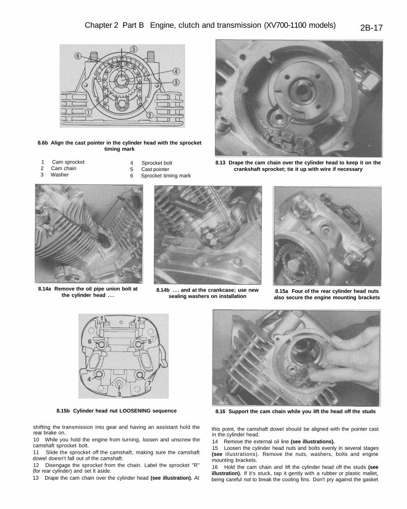
Chapter 2 Part B Engine, clutch and transmission (XV700-1100 models) 2B-17
8.6b Align the cast pointer in the cylinder head with the sprockettiming mark
1 Cam sprocket2 Cam chain3 Washer
4 Sprocket bolt5 Cast pointer6 Sprocket timing mark
8.13 Drape the cam chain over the cylinder head to keep it on thecrankshaft sprocket; tie it up with wire if necessary
8.14a Remove the oil pipe union bolt atthe cylinder head . . .
8.14b . . . and at the crankcase; use newsealing washers on installation
8.15a Four of the rear cylinder head nutsalso secure the engine mounting brackets
8.15b Cylinder head nut LOOSENING sequence 8.16 Support the cam chain while you lift the head off the studs
shifting the transmission into gear and having an assistant hold therear brake on.10 While you hold the engine from turning, loosen and unscrew thecamshaft sprocket bolt.11 Slide the sprocket off the camshaft, making sure the camshaftdowel doesn't fall out of the camshaft.12 Disengage the sprocket from the chain. Label the sprocket "R"(for rear cylinder) and set it aside.13 Drape the cam chain over the cylinder head (see illustration). At
this point, the camshaft dowel should be aligned with the pointer castin the cylinder head.14 Remove the external oil line (see illustrations).15 Loosen the cylinder head nuts and bolts evenly in several stages(see illustrations). Remove the nuts, washers, bolts and enginemounting brackets.16 Hold the cam chain and lift the cylinder head off the studs (seeillustration). If it's stuck, tap it gently with a rubber or plastic mallet,being careful not to break the cooling fins. Don't pry against the gasket
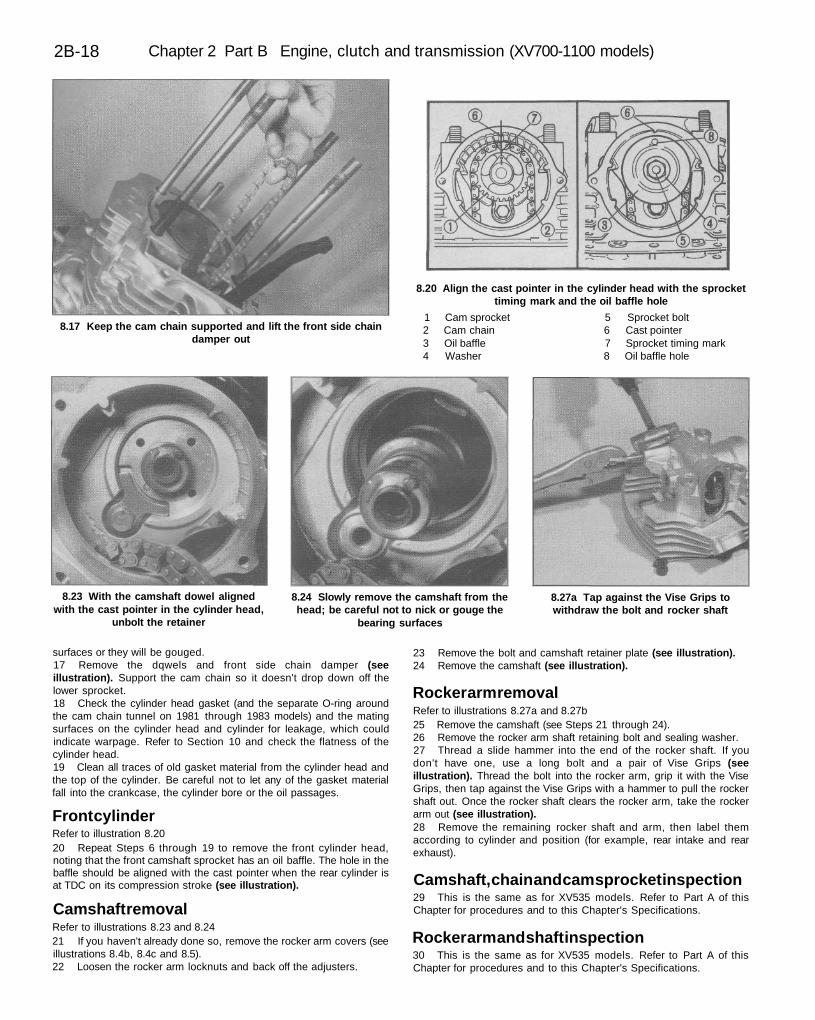
2B-18 Chapter 2 Part B Engine, clutch and transmission (XV700-1100 models)
8.17 Keep the cam chain supported and lift the front side chaindamper out
8.20 Align the cast pointer in the cylinder head with the sprockettiming mark and the oil baffle hole
1 Cam sprocket 5 Sprocket bolt2 Cam chain 6 Cast pointer3 Oil baffle 7 Sprocket timing mark4 Washer 8 Oil baffle hole
8.23 With the camshaft dowel alignedwith the cast pointer in the cylinder head,
unbolt the retainer
8.24 Slowly remove the camshaft from thehead; be careful not to nick or gouge the
bearing surfaces
8.27a Tap against the Vise Grips towithdraw the bolt and rocker shaft
surfaces or they will be gouged.17 Remove the dqwels and front side chain damper (seeillustration). Support the cam chain so it doesn't drop down off thelower sprocket.18 Check the cylinder head gasket (and the separate O-ring aroundthe cam chain tunnel on 1981 through 1983 models) and the matingsurfaces on the cylinder head and cylinder for leakage, which couldindicate warpage. Refer to Section 10 and check the flatness of thecylinder head.19 Clean all traces of old gasket material from the cylinder head andthe top of the cylinder. Be careful not to let any of the gasket materialfall into the crankcase, the cylinder bore or the oil passages.
Front cylinderRefer to illustration 8.2020 Repeat Steps 6 through 19 to remove the front cylinder head,noting that the front camshaft sprocket has an oil baffle. The hole in thebaffle should be aligned with the cast pointer when the rear cylinder isat TDC on its compression stroke (see illustration).
Camshaft removalRefer to illustrations 8.23 and 8.2421 If you haven't already done so, remove the rocker arm covers (seeillustrations 8.4b, 8.4c and 8.5).22 Loosen the rocker arm locknuts and back off the adjusters.
23 Remove the bolt and camshaft retainer plate (see illustration).24 Remove the camshaft (see illustration).
Rocker arm removalRefer to illustrations 8.27a and 8.27b25 Remove the camshaft (see Steps 21 through 24).26 Remove the rocker arm shaft retaining bolt and sealing washer.27 Thread a slide hammer into the end of the rocker shaft. If youdon't have one, use a long bolt and a pair of Vise Grips (seeillustration). Thread the bolt into the rocker arm, grip it with the ViseGrips, then tap against the Vise Grips with a hammer to pull the rockershaft out. Once the rocker shaft clears the rocker arm, take the rockerarm out (see illustration).28 Remove the remaining rocker shaft and arm, then label themaccording to cylinder and position (for example, rear intake and rearexhaust).
Camshaft, chain and cam sprocket inspection29 This is the same as for XV535 models. Refer to Part A of thisChapter for procedures and to this Chapter's Specifications.
Rocker arm and shaft inspection30 This is the same as for XV535 models. Refer to Part A of thisChapter for procedures and to this Chapter's Specifications.
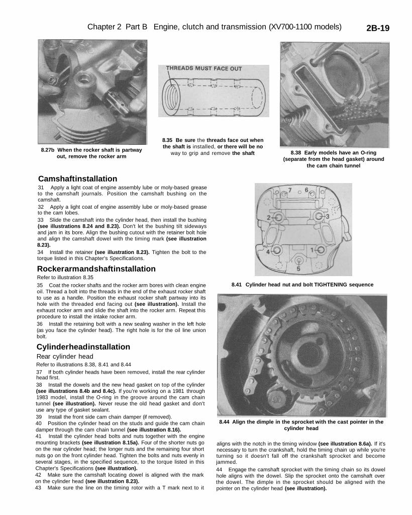
Chapter 2 Part B Engine, clutch and transmission (XV700-1100 models) 2B-19
8.27b When the rocker shaft is partwayout, remove the rocker arm
8.35 Be sure the threads face out whenthe shaft is installed, or there will be no
way to grip and remove the shaft 8.38 Early models have an O-ring(separate from the head gasket) around
the cam chain tunnel
8.41 Cylinder head nut and bolt TIGHTENING sequence
8.44 Align the dimple in the sprocket with the cast pointer in thecylinder head
Camshaft installation31 Apply a light coat of engine assembly lube or moly-based greaseto the camshaft journals. Position the camshaft bushing on thecamshaft.32 Apply a light coat of engine assembly lube or moly-based greaseto the cam lobes.33 Slide the camshaft into the cylinder head, then install the bushing(see illustrations 8.24 and 8.23). Don't let the bushing tilt sidewaysand jam in its bore. Align the bushing cutout with the retainer bolt holeand align the camshaft dowel with the timing mark (see illustration8.23).34 Install the retainer (see illustration 8.23). Tighten the bolt to thetorque listed in this Chapter's Specifications.
Rocker arm and shaft installationRefer to illustration 8.35
35 Coat the rocker shafts and the rocker arm bores with clean engineoil. Thread a bolt into the threads in the end of the exhaust rocker shaftto use as a handle. Position the exhaust rocker shaft partway into itshole with the threaded end facing out (see illustration). Install theexhaust rocker arm and slide the shaft into the rocker arm. Repeat thisprocedure to install the intake rocker arm.36 Install the retaining bolt with a new sealing washer in the left hole(as you face the cylinder head). The right hole is for the oil line unionbolt.
Cylinder head installationRear cylinder headRefer to illustrations 8.38, 8.41 and 8.4437 If both cylinder heads have been removed, install the rear cylinderhead first.38 Install the dowels and the new head gasket on top of the cylinder(see illustrations 8.4b and 8.4c). If you're working on a 1981 through1983 model, install the O-ring in the groove around the cam chaintunnel (see illustration). Never reuse the old head gasket and don'tuse any type of gasket sealant.39 Install the front side cam chain damper (if removed).40 Position the cylinder head on the studs and guide the cam chaindamper through the cam chain tunnel (see illustration 8.16).41 Install the cylinder head bolts and nuts together with the enginemounting brackets (see illustration 8.15a). Four of the shorter nuts goon the rear cylinder head; the longer nuts and the remaining four shortnuts go on the front cylinder head. Tighten the bolts and nuts evenly inseveral stages, in the specified sequence, to the torque listed in thisChapter's Specifications (see illustration).42 Make sure the camshaft locating dowel is aligned with the markon the cylinder head (see illustration 8.23).43 Make sure the line on the timing rotor with a T mark next to it
aligns with the notch in the timing window (see illustration 8.6a). If it'snecessary to turn the crankshaft, hold the timing chain up while you'returning so it doesn't fall off the crankshaft sprocket and becomejammed.44 Engage the camshaft sprocket with the timing chain so its dowelhole aligns with the dowel. Slip the sprocket onto the camshaft overthe dowel. The dimple in the sprocket should be aligned with thepointer on the cylinder head (see illustration).
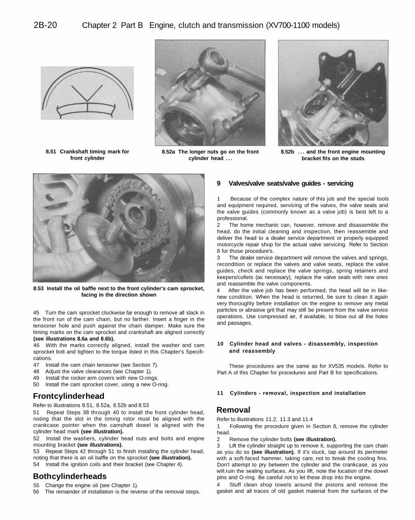
2B-20 Chapter 2 Part B Engine, clutch and transmission (XV700-1100 models)
8.51 Crankshaft timing mark forfront cylinder
8.52a The longer nuts go on the frontcylinder head . . .
8.52b . . . and the front engine mountingbracket fits on the studs
8.53 Install the oil baffle next to the front cylinder's cam sprocket,facing in the direction shown
45 Turn the cam sprocket clockwise far enough to remove all slack inthe front run of the cam chain, but no farther. Insert a finger in thetensioner hole and push against the chain damper. Make sure thetiming marks on the cam sprocket and crankshaft are aligned correctly(see illustrations 8.6a and 8.6b).46 With the marks correctly aligned, install the washer and camsprocket bolt and tighten to the torque listed in this Chapter's Specifi-cations.47 Install the cam chain tensioner (see Section 7).48 Adjust the valve clearances (see Chapter 1).49 Install the rocker arm covers with new O-rings.50 Install the cam sprocket cover, using a new O-ring.
Front cylinder headRefer to illustrations 8.51, 8.52a, 8.52b and 8.5351 Repeat Steps 38 through 40 to install the front cylinder head,noting that the slot in the timing rotor must be aligned with thecrankcase pointer when the camshaft dowel is aligned with thecylinder head mark (see illustration).52 Install the washers, cylinder head nuts and bolts and enginemounting bracket (see illustrations).53 Repeat Steps 42 through 51 to finish installing the cylinder head,noting that there is an oil baffle on the sprocket (see illustration).54 Install the ignition coils and their bracket (see Chapter 4).
Both cylinder heads55 Change the engine oil (see Chapter 1).56 The remainder of installation is the reverse of the removal steps.
9 Valves/valve seats/valve guides - servicing
1 Because of the complex nature of this job and the special toolsand equipment required, servicing of the valves, the valve seats andthe valve guides (commonly known as a valve job) is best left to aprofessional.2 The home mechanic can, however, remove and disassemble thehead, do the initial cleaning and inspection, then reassemble anddeliver the head to a dealer service department or properly equippedmotorcycle repair shop for the actual valve servicing. Refer to Section8 for those procedure's.3 The dealer service department will remove the valves and springs,recondition or replace the valves and valve seats, replace the valveguides, check and replace the valve springs, spring retainers andkeepers/collets (as necessary), replace the valve seals with new onesand reassemble the valve components.4 After the valve job has been performed, the head will be in like-new condition. When the head is returned, be sure to clean it againvery thoroughly before installation on the engine to remove any metalparticles or abrasive grit that may still be present from the valve serviceoperations. Use compressed air, if available, to blow out all the holesand passages.
10 Cylinder head and valves - disassembly, inspectionand reassembly
These procedures are the same as for XV535 models. Refer toPart A of this Chapter for procedures and Part B for specifications.
11 Cylinders - removal, inspection and installation
RemovalRefer to illustrations 11.2, 11.3 and 11.41 Following the procedure given in Section 8, remove the cylinderhead.2 Remove the cylinder bolts (see illustration).3 Lift the cylinder straight up to remove it, supporting the cam chainas you do so (see illustration). If it's stuck, tap around its perimeterwith a soft-faced hammer, taking care, not to break the cooling fins.Don't attempt to pry between the cylinder and the crankcase, as youwill.ruin the sealing surfaces. As you lift, note the location of the dowelpins and O-ring. Be careful not to let these drop into the engine.4 Stuff clean shop towels around the pistons and remove thegasket and all traces of old gasket material from the surfaces of the
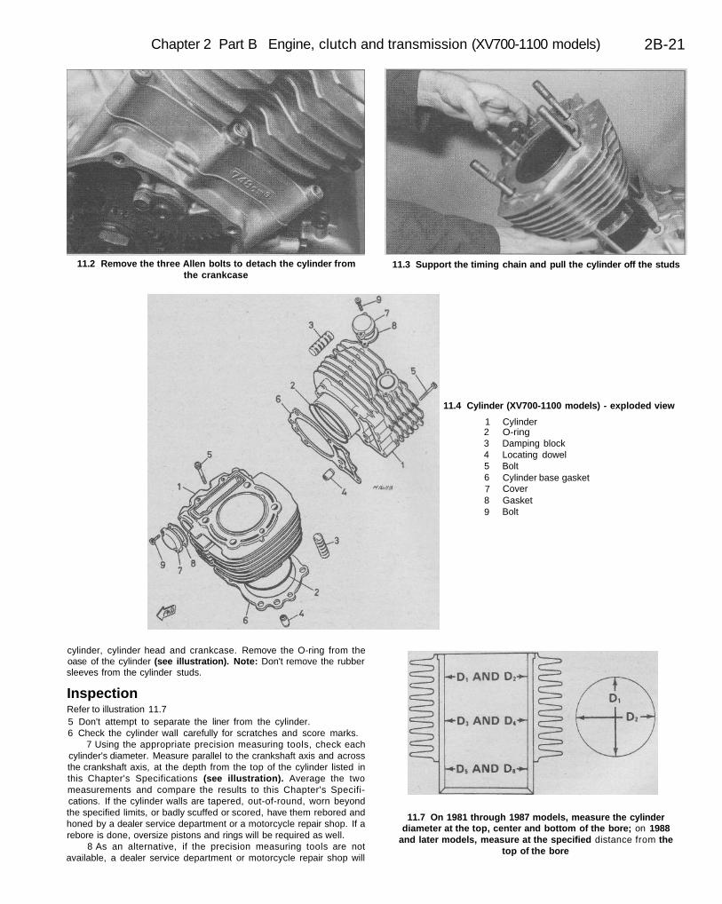
Chapter 2 Part B Engine, clutch and transmission (XV700-1100 models) 2B-21
11.2 Remove the three Allen bolts to detach the cylinder fromthe crankcase
11.3 Support the timing chain and pull the cylinder off the studs
11.4 Cylinder (XV700-1100 models) - exploded view
123456789
CylinderO-ringDamping blockLocating dowelBoltCylinder base gasketCoverGasketBolt
cylinder, cylinder head and crankcase. Remove the O-ring from theoase of the cylinder (see illustration). Note: Don't remove the rubbersleeves from the cylinder studs.
InspectionRefer to illustration 11.75 Don't attempt to separate the liner from the cylinder.6 Check the cylinder wall carefully for scratches and score marks.
7 Using the appropriate precision measuring tools, check eachcylinder's diameter. Measure parallel to the crankshaft axis and acrossthe crankshaft axis, at the depth from the top of the cylinder listed inthis Chapter's Specifications (see illustration). Average the twomeasurements and compare the results to this Chapter's Specifi-cations. If the cylinder walls are tapered, out-of-round, worn beyondthe specified limits, or badly scuffed or scored, have them rebored andhoned by a dealer service department or a motorcycle repair shop. If arebore is done, oversize pistons and rings will be required as well.
8 As an alternative, if the precision measuring tools are notavailable, a dealer service department or motorcycle repair shop will
11.7 On 1981 through 1987 models, measure the cylinderdiameter at the top, center and bottom of the bore; on 1988
and later models, measure at the specified distance from thetop of the bore
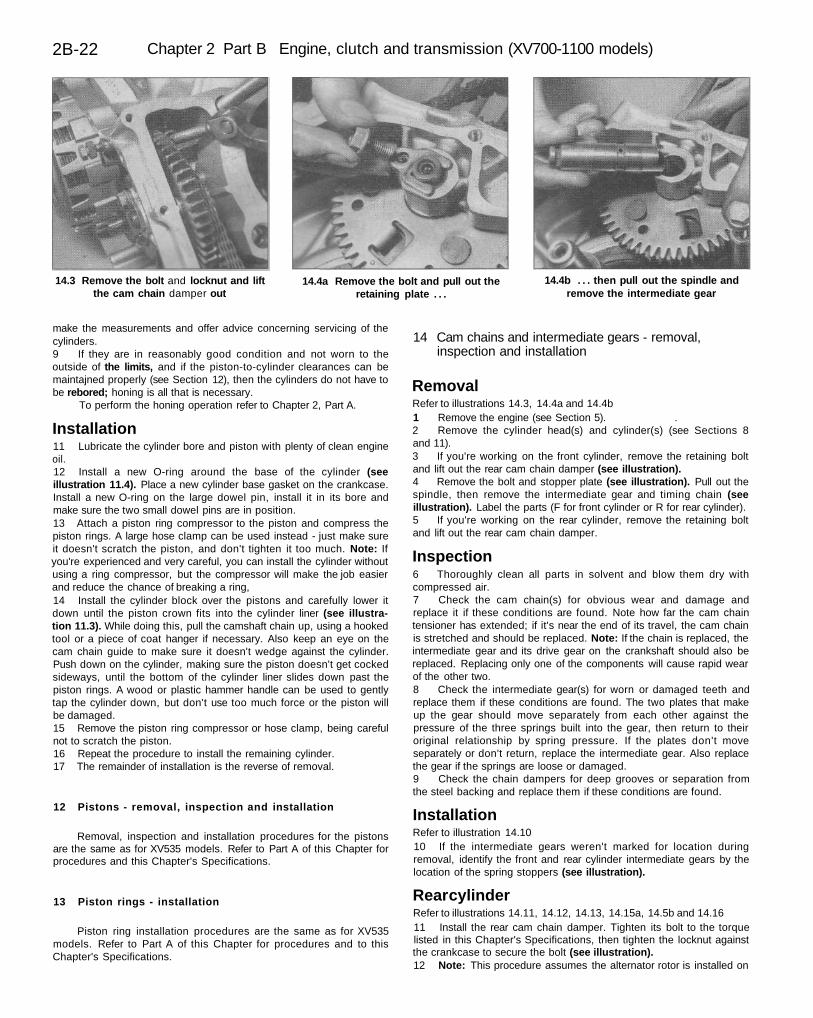
2B-22 Chapter 2 Part B Engine, clutch and transmission (XV700-1100 models)
14.3 Remove the bolt and locknut and liftthe cam chain damper out
14.4a Remove the bolt and pull out theretaining plate . . .
14.4b . . . then pull out the spindle andremove the intermediate gear
make the measurements and offer advice concerning servicing of thecylinders.9 If they are in reasonably good condition and not worn to theoutside of the limits, and if the piston-to-cylinder clearances can bemaintajned properly (see Section 12), then the cylinders do not have tobe rebored; honing is all that is necessary.
To perform the honing operation refer to Chapter 2, Part A.
Installation11 Lubricate the cylinder bore and piston with plenty of clean engineoil.12 Install a new O-ring around the base of the cylinder (seeillustration 11.4). Place a new cylinder base gasket on the crankcase.Install a new O-ring on the large dowel pin, install it in its bore andmake sure the two small dowel pins are in position.13 Attach a piston ring compressor to the piston and compress thepiston rings. A large hose clamp can be used instead - just make sureit doesn't scratch the piston, and don't tighten it too much. Note: Ifyou're experienced and very careful, you can install the cylinder withoutusing a ring compressor, but the compressor will make the job easierand reduce the chance of breaking a ring,14 Install the cylinder block over the pistons and carefully lower itdown until the piston crown fits into the cylinder liner (see illustra-tion 11.3). While doing this, pull the camshaft chain up, using a hookedtool or a piece of coat hanger if necessary. Also keep an eye on thecam chain guide to make sure it doesn't wedge against the cylinder.Push down on the cylinder, making sure the piston doesn't get cockedsideways, until the bottom of the cylinder liner slides down past thepiston rings. A wood or plastic hammer handle can be used to gentlytap the cylinder down, but don't use too much force or the piston willbe damaged.15 Remove the piston ring compressor or hose clamp, being carefulnot to scratch the piston.16 Repeat the procedure to install the remaining cylinder.17 The remainder of installation is the reverse of removal.
12 Pistons - removal, inspection and installation
Removal, inspection and installation procedures for the pistonsare the same as for XV535 models. Refer to Part A of this Chapter forprocedures and this Chapter's Specifications.
13 Piston rings - installation
Piston ring installation procedures are the same as for XV535models. Refer to Part A of this Chapter for procedures and to thisChapter's Specifications.
14 Cam chains and intermediate gears - removal,inspection and installation
RemovalRefer to illustrations 14.3, 14.4a and 14.4b1 Remove the engine (see Section 5). .2 Remove the cylinder head(s) and cylinder(s) (see Sections 8and 11).3 If you're working on the front cylinder, remove the retaining boltand lift out the rear cam chain damper (see illustration).4 Remove the bolt and stopper plate (see illustration). Pull out thespindle, then remove the intermediate gear and timing chain (seeillustration). Label the parts (F for front cylinder or R for rear cylinder).5 If you're working on the rear cylinder, remove the retaining boltand lift out the rear cam chain damper.
Inspection6 Thoroughly clean all parts in solvent and blow them dry withcompressed air.7 Check the cam chain(s) for obvious wear and damage andreplace it if these conditions are found. Note how far the cam chaintensioner has extended; if it's near the end of its travel, the cam chainis stretched and should be replaced. Note: If the chain is replaced, theintermediate gear and its drive gear on the crankshaft should also bereplaced. Replacing only one of the components will cause rapid wearof the other two.8 Check the intermediate gear(s) for worn or damaged teeth andreplace them if these conditions are found. The two plates that makeup the gear should move separately from each other against thepressure of the three springs built into the gear, then return to theiroriginal relationship by spring pressure. If the plates don't moveseparately or don't return, replace the intermediate gear. Also replacethe gear if the springs are loose or damaged.9 Check the chain dampers for deep grooves or separation fromthe steel backing and replace them if these conditions are found.
InstallationRefer to illustration 14.1010 If the intermediate gears weren't marked for location duringremoval, identify the front and rear cylinder intermediate gears by thelocation of the spring stoppers (see illustration).
Rear cylinderRefer to illustrations 14.11, 14.12, 14.13, 14.15a, 14.5b and 14.1611 Install the rear cam chain damper. Tighten its bolt to the torquelisted in this Chapter's Specifications, then tighten the locknut againstthe crankcase to secure the bolt (see illustration).12 Note: This procedure assumes the alternator rotor is installed on
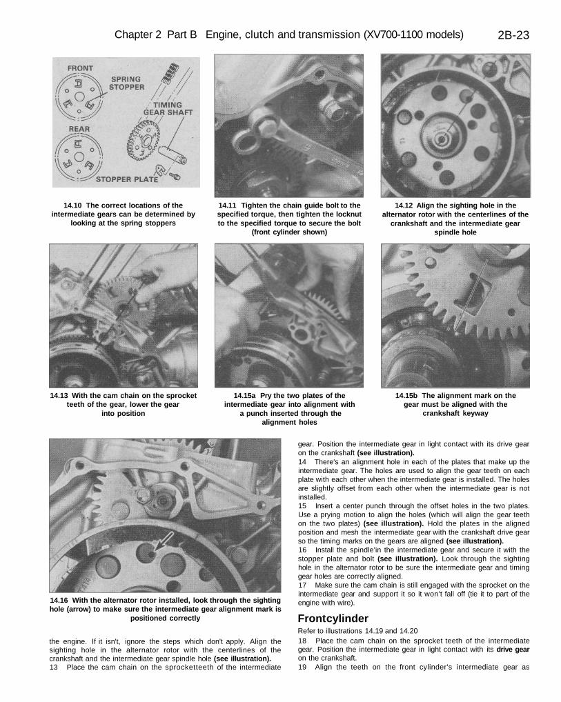
Chapter 2 Part B Engine, clutch and transmission (XV700-1100 models) 2B-23
14.10 The correct locations of theintermediate gears can be determined by
looking at the spring stoppers
14.11 Tighten the chain guide bolt to thespecified torque, then tighten the locknutto the specified torque to secure the bolt
(front cylinder shown)
14.12 Align the sighting hole in thealternator rotor with the centerlines of the
crankshaft and the intermediate gearspindle hole
14.13 With the cam chain on the sprocketteeth of the gear, lower the gear
into position
14.15a Pry the two plates of theintermediate gear into alignment with
a punch inserted through thealignment holes
14.15b The alignment mark on thegear must be aligned with the
crankshaft keyway
14.16 With the alternator rotor installed, look through the sightinghole (arrow) to make sure the intermediate gear alignment mark is
positioned correctly
the engine. If it isn't, ignore the steps which don't apply. Align thesighting hole in the alternator rotor with the centerlines of thecrankshaft and the intermediate gear spindle hole (see illustration).13 Place the cam chain on the sprocketteeth of the intermediate
gear. Position the intermediate gear in light contact with its drive gearon the crankshaft (see illustration).14 There's an alignment hole in each of the plates that make up theintermediate gear. The holes are used to align the gear teeth on eachplate with each other when the intermediate gear is installed. The holesare slightly offset from each other when the intermediate gear is notinstalled.15 Insert a center punch through the offset holes in the two plates.Use a prying motion to align the holes (which will align the gear teethon the two plates) (see illustration). Hold the plates in the alignedposition and mesh the intermediate gear with the crankshaft drive gearso the timing marks on the gears are aligned (see illustration).16 Install the spindle'in the intermediate gear and secure it with thestopper plate and bolt (see illustration). Look through the sightinghole in the alternator rotor to be sure the intermediate gear and timinggear holes are correctly aligned.17 Make sure the cam chain is still engaged with the sprocket on theintermediate gear and support it so it won't fall off (tie it to part of theengine with wire).
Front cylinderRefer to illustrations 14.19 and 14.2018 Place the cam chain on the sprocket teeth of the intermediategear. Position the intermediate gear in light contact with its drive gearon the crankshaft.19 Align the teeth on the front cylinder's intermediate gear as
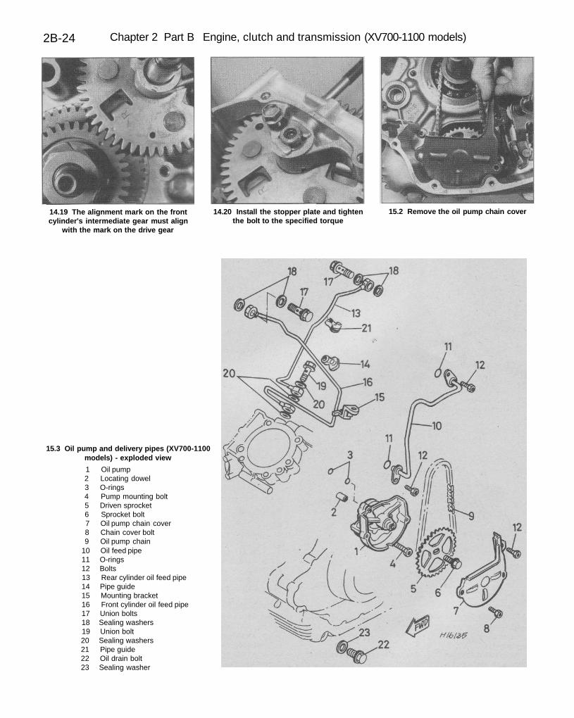
2B-24 Chapter 2 Part B Engine, clutch and transmission (XV700-1100 models)
14.19 The alignment mark on the frontcylinder's intermediate gear must align
with the mark on the drive gear
14.20 Install the stopper plate and tightenthe bolt to the specified torque
15.2 Remove the oil pump chain cover
15.3 Oil pump and delivery pipes (XV700-1100models) - exploded view
1 Oil pump2 Locating dowel3 O-rings4 Pump mounting bolt5 Driven sprocket6 Sprocket bolt7 Oil pump chain cover8 Chain cover bolt9 Oil pump chain
10 Oil feed pipe11 O-rings12 Bolts13 Rear cylinder oil feed pipe14 Pipe guide15 Mounting bracket16 Front cylinder oil feed pipe17 Union bolts18 Sealing washers19 Union bolt20 Sealing washers21 Pipe guide22 Oil drain bolt23 Sealing washer
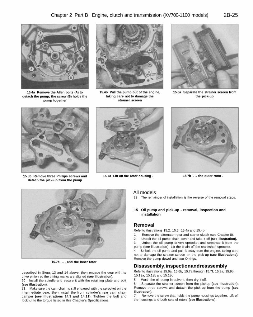
Chapter 2 Part B Engine, clutch and transmission (XV700-1100 models) 2B-25
15.4a Remove the Allen bolts (A) todetach the pump; the screw (B) holds the
pump together'
15.4b Pull the pump out of the engine,taking care not to damage the
strainer screen
15.6a Separate the strainer screen fromthe pick-up
15.6b Remove three Phillips screws anddetach the pick-up from the pump
15.7a Lift off the rotor housing . 15.7b . . . the outer rotor .
15.7c . . . and the inner rotor
described in Steps 13 and 14 above, then engage the gear with itsdrive pinion so the timing marks are aligned (see illustration).20 Install the spindle and secure it with the retaining plate and bolt(see illustration).21 Make sure the cam chain is still engaged with the sprocket on theintermediate gear, then install the front cylinder's rear cam chaindamper (see illustrations 14.3 and 14.11). Tighten the bolt andlocknut to the torque listed in this Chapter's Specifications.
All models22 The remainder of installation is the reverse of the removal steps.
15 Oil pump and pick-up - removal, inspection andinstallation
RemovalRefer to illustrations 15.2. 15.3. 15.4a and 15.4b1 Remove the alternator rotor and starter clutch (see Chapter 8).2 Unbolt the oil pump chain cover and take it off (see illustration).3 Unbolt the oil pump driven sprocket and separate it from thepump (see illustration). Lift the chain off the crankshaft sprocket.4 Unbolt the oil pump and pull it away from the engine, taking carenot to damage the strainer screen on the pick-up (see illustrations).Remove the pump dowel and two O-rings.
Disassembly, inspection and reassemblyRefer to illustrations 15.6a, 15.6b, 15.7a through 15.7f, 15.9a, 15.9b,15.13a, 15.13b and 15.13c5 Wash the oil pump in solvent, then dry it off.6 Separate the strainer screen from the pickup (see illustration).Remove three screws and detach the pick-up from the pump (seeillustration).7 Remove the screw that holds the pump housings together. Lift offthe housings and both sets of rotors (see illustrations).
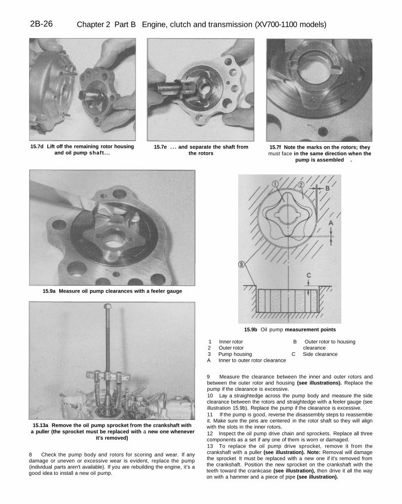
2B-26 Chapter 2 Part B Engine, clutch and transmission (XV700-1100 models)
15.7d Lift off the remaining rotor housingand oil pump shaft . . .
15.7e . . . and separate the shaft fromthe rotors
15.7f Note the marks on the rotors; theymust face in the same direction when the
pump is assembled .
15.9a Measure oil pump clearances with a feeler gauge
15.9b Oil pump measurement points
1 Inner rotor B Outer rotor to housing2 Outer rotor clearance3 Pump housing C Side clearanceA Inner to outer rotor clearance
15.13a Remove the oil pump sprocket from the crankshaft witha puller (the sprocket must be replaced with a new one whenever
it's removed)
8 Check the pump body and rotors for scoring and wear. If anydamage or uneven or excessive wear is evident, replace the pump(individual parts aren't available). If you are rebuilding the engine, it's agood idea to install a new oil pump.
9 Measure the clearance between the inner and outer rotors andbetween the outer rotor and housing (see illustrations). Replace thepump if the clearance is excessive.10 Lay a straightedge across the pump body and measure the sideclearance between the rotors and straightedge with a feeler gauge (seeillustration 15.9b). Replace the pump if the clearance is excessive.11 If the pump is good, reverse the disassembly steps to reassembleit. Make sure the pins are centered in the rotor shaft so they will alignwith the slots in the inner rotors.12 Inspect the oil pump drive chain and sprockets. Replace all threecomponents as a set if any one of them is worn or damaged.13 To replace the oil pump drive sprocket, remove it from thecrankshaft with a puller (see illustration). Note: Removal will damagethe sprocket It must be replaced with a new one if it's removed fromthe crankshaft. Position the new sprocket on the crankshaft with theteeth toward the crankcase (see illustration), then drive it all the wayon with a hammer and a piece of pipe (see illustration).
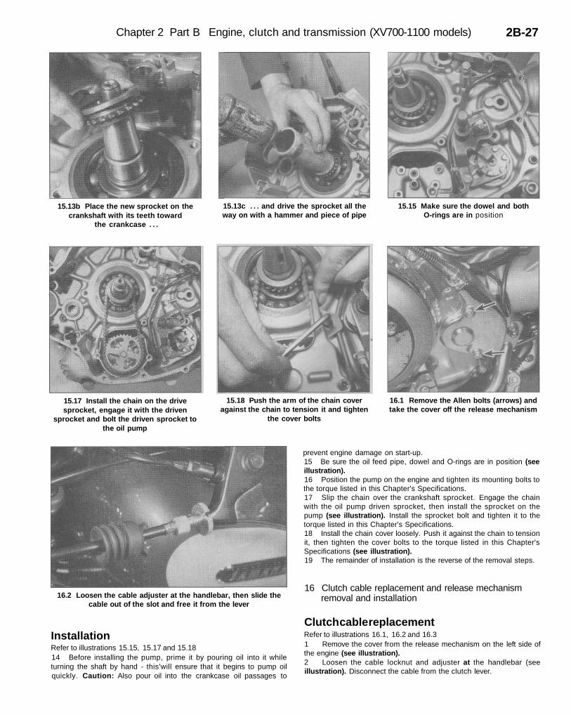
Chapter 2 Part B Engine, clutch and transmission (XV700-1100 models) 2B-27
15.13b Place the new sprocket on thecrankshaft with its teeth toward
the crankcase . . .
15.13c . . . and drive the sprocket all theway on with a hammer and piece of pipe
15.15 Make sure the dowel and bothO-rings are in position
15.17 Install the chain on the drivesprocket, engage it with the driven
sprocket and bolt the driven sprocket tothe oil pump
15.18 Push the arm of the chain coveragainst the chain to tension it and tighten
the cover bolts
16.1 Remove the Allen bolts (arrows) andtake the cover off the release mechanism
16.2 Loosen the cable adjuster at the handlebar, then slide thecable out of the slot and free it from the lever
InstallationRefer to illustrations 15.15, 15.17 and 15.1814 Before installing the pump, prime it by pouring oil into it whileturning the shaft by hand - this'will ensure that it begins to pump oilquickly. Caution: Also pour oil into the crankcase oil passages to
prevent engine damage on start-up.15 Be sure the oil feed pipe, dowel and O-rings are in position (seeillustration).16 Position the pump on the engine and tighten its mounting bolts tothe torque listed in this Chapter's Specifications.17 Slip the chain over the crankshaft sprocket. Engage the chainwith the oil pump driven sprocket, then install the sprocket on thepump (see illustration). Install the sprocket bolt and tighten it to thetorque listed in this Chapter's Specifications.18 Install the chain cover loosely. Push it against the chain to tensionit, then tighten the cover bolts to the torque listed in this Chapter'sSpecifications (see illustration).19 The remainder of installation is the reverse of the removal steps.
16 Clutch cable replacement and release mechanismremoval and installation
Clutch cable replacementRefer to illustrations 16.1, 16.2 and 16.31 Remove the cover from the release mechanism on the left side ofthe engine (see illustration).2 Loosen the cable locknut and adjuster at the handlebar (seeillustration). Disconnect the cable from the clutch lever.
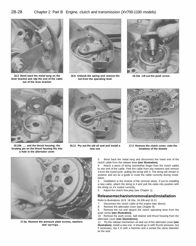
2B-28 Chapter 2 Part B Engine, clutch and transmission (XV700-1100 models)
16.3 Bend back the metal tang on thelever bracket and slip the end of the cable
out of the lever bracket
16.9 Unhook the spring and remove thenut from the operating lever
16.10a Lift out the push screw .
16.10b . . . and the thrust housing; thelocating pin on the thrust housing fits into
a hole in the alternator cover
16.11 Pry out the old oil seal and install anew one
17.3 Remove the clutch cover; note thelocations of the dowels
17.4a Remove the pressure plate screws, washersand springs...
3 Bend back the metal tang and disconnect the lower end of theclutch cable from the release lever (see illustration).4 Attach a piece of string (somewhat longer than the clutch cable)to one end of the cable. Free the cable from any retainers and removeit from the motorcycle, pulling the string with it. The string will remain inposition and act as a guide to route the cable correctly during instal-lation.5 Installation is the reverse of the removal steps. If you're installinga new cable, attach the string to it and pull the cable into position withthe string so it's routed correctly.6 Adjust the clutch free-play (see Chapter 1).
Release mechanism removal and installationRefer to illustrations 16.9, 16.10a, 16.10b and 16.117 Disconnect the clutch cable at the engine (see above).8 Remove the alternator cover (see Chapter 8).9 Remove the nut and detach the clutch operating lever from thepush screw (see illustration).10 Remove the push screw, ball retainer and thrust housing from thealternator cover (see illustrations).11 Pry the release mechanism oil seal out of the alternator cover (seeillustration). Install a new one. It should go in with thumb pressure, butif necessary, tap it in with a hammer and a socket the same diameteras the seal.
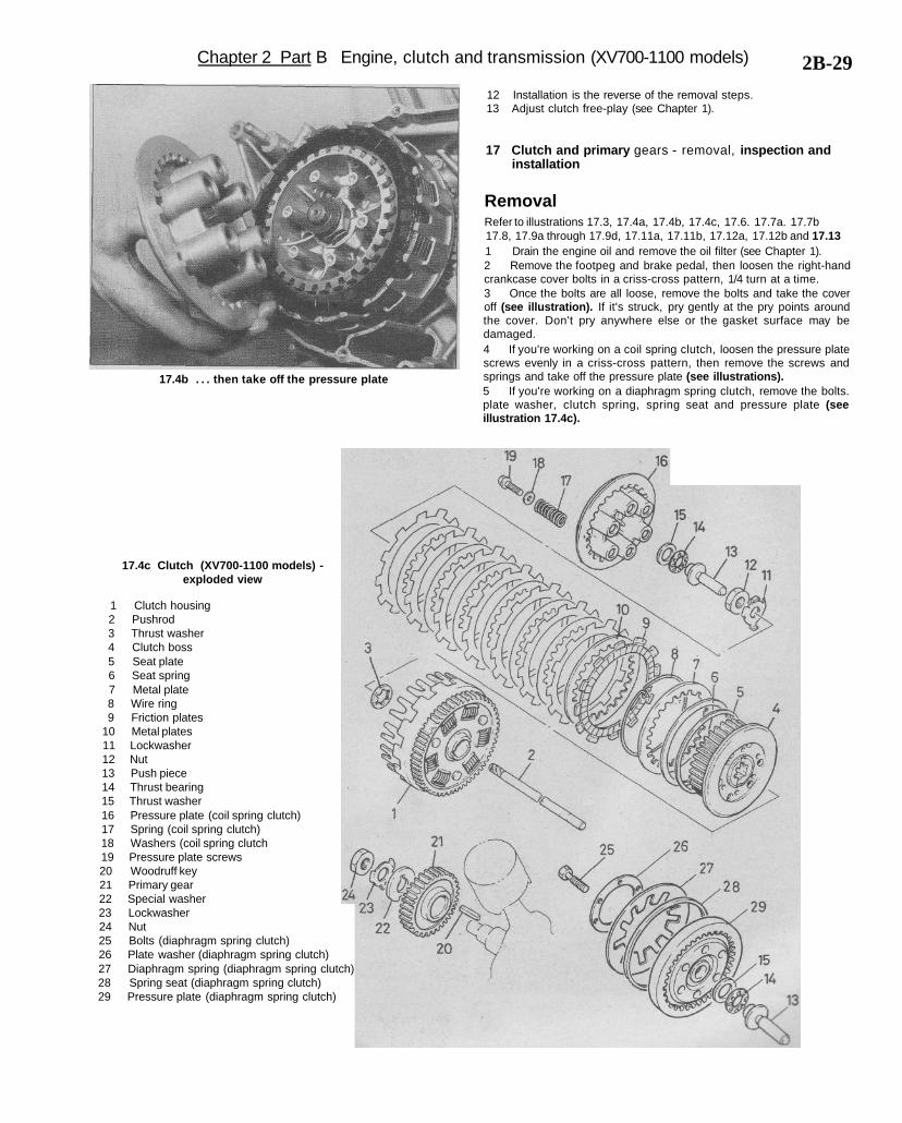
Chapter 2 Part B Engine, clutch and transmission (XV700-1100 models) 2B-29
17.4b . . . then take off the pressure plate
12 Installation is the reverse of the removal steps.13 Adjust clutch free-play (see Chapter 1).
17 Clutch and primary gears - removal, inspection andinstallation
RemovalRefer to illustrations 17.3, 17.4a, 17.4b, 17.4c, 17.6. 17.7a. 17.7b17.8, 17.9a through 17.9d, 17.11a, 17.11b, 17.12a, 17.12b and 17.131 Drain the engine oil and remove the oil filter (see Chapter 1).2 Remove the footpeg and brake pedal, then loosen the right-handcrankcase cover bolts in a criss-cross pattern, 1/4 turn at a time.3 Once the bolts are all loose, remove the bolts and take the coveroff (see illustration). If it's struck, pry gently at the pry points aroundthe cover. Don't pry anywhere else or the gasket surface may bedamaged.4 If you're working on a coil spring clutch, loosen the pressure platescrews evenly in a criss-cross pattern, then remove the screws andsprings and take off the pressure plate (see illustrations).5 If you're working on a diaphragm spring clutch, remove the bolts.plate washer, clutch spring, spring seat and pressure plate (seeillustration 17.4c).
17.4c Clutch (XV700-1100 models) -exploded view
1 Clutch housing2 Pushrod3 Thrust washer4 Clutch boss5 Seat plate6 Seat spring7 Metal plate8 Wire ring9 Friction plates
10 Metal plates11 Lockwasher12 Nut13 Push piece14 Thrust bearing15 Thrust washer16 Pressure plate (coil spring clutch)17 Spring (coil spring clutch)18 Washers (coil spring clutch19 Pressure plate screws20 Woodruff key21 Primary gear22 Special washer23 Lockwasher24 Nut25 Bolts (diaphragm spring clutch)26 Plate washer (diaphragm spring clutch)27 Diaphragm spring (diaphragm spring clutch)28 Spring seat (diaphragm spring clutch)29 Pressure plate (diaphragm spring clutch)

2B-30 Chapter 2 Part B Engine, clutch and transmission (XV700-1100 models)
17.6 Remove the thrust washer andthrust bearing
17.7a Remove the push piece . . . 17.7b . . . and the pushrod
17.8 Remove the clutch plates 17.9a Bend the lockwasher tab away fromthe nut
17.9b You'll need a tool to keep the clutchfrom turning; this is one type of Yamaha
special t o o l . . .
17.9c . . . this is another type
17.9d Hold the clutch housing so it won't turn and loosen the nut
6 Remove the thrust washer and thrust bearing (see illustration).7 Remove the push piece and pushrod (see illustrations).8 Remove the clutch plates (a friction plate comes off first, followedby a steel plate, then alternating friction and steel plates) (seeillustration).9 Bend back the lockwasher on the clutch boss nut (seeillustration). Loosen the nut, using a special holding tool (Yamaha toolno. YM-91402, part no. 90890-04086 or equivalent) to prevent theclutch housing from turning (see illustrations). An alternative to these
tool can be fabricated from some steel strap, bent at the ends andbolted together in the middle (see Part A of this Chapter). You can alsomake a holding tool by drilling through a steel plate and friction plateand bolting them together (see Part A of this Chapter). Slip the boltedplates into their normal installed position to lock the clutch housingand clutch boss together. To keep the engine from turning, wedge arag between the teeth of the primary drive gear and the driven gear onthe clutch housing. Once the nut is loose, remove it.10 Remove the lockwasher and discard it. Use a new one duringinstallation.
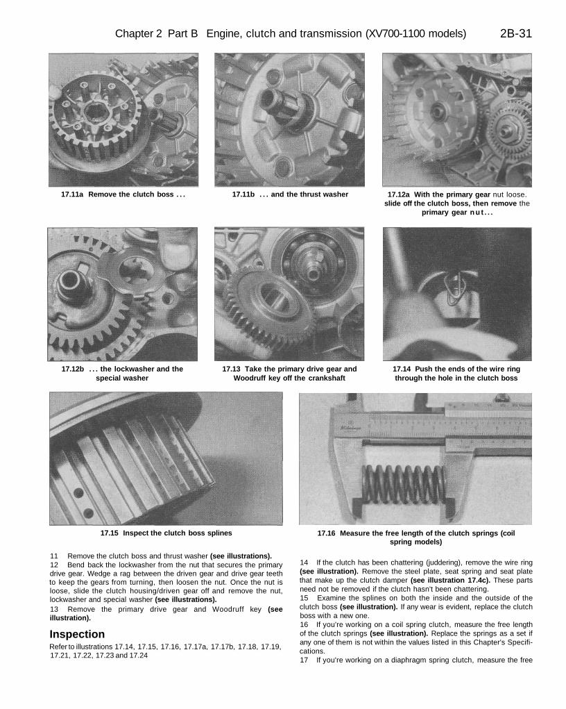
Chapter 2 Part B Engine, clutch and transmission (XV700-1100 models) 2B-31
17.11a Remove the clutch boss . . . 17.11b . . . and the thrust washer 17.12a With the primary gear nut loose.slide off the clutch boss, then remove the
primary gear n u t . . .
17.12b . . . the lockwasher and thespecial washer
17.13 Take the primary drive gear andWoodruff key off the crankshaft
17.14 Push the ends of the wire ringthrough the hole in the clutch boss
17.15 Inspect the clutch boss splines 17.16 Measure the free length of the clutch springs (coilspring models)
11 Remove the clutch boss and thrust washer (see illustrations).12 Bend back the lockwasher from the nut that secures the primarydrive gear. Wedge a rag between the driven gear and drive gear teethto keep the gears from turning, then loosen the nut. Once the nut isloose, slide the clutch housing/driven gear off and remove the nut,lockwasher and special washer (see illustrations).13 Remove the primary drive gear and Woodruff key (seeillustration).
InspectionRefer to illustrations 17.14, 17.15, 17.16, 17.17a, 17.17b, 17.18, 17.19,17.21, 17.22, 17.23 and 17.24
14 If the clutch has been chattering (juddering), remove the wire ring(see illustration). Remove the steel plate, seat spring and seat platethat make up the clutch damper (see illustration 17.4c). These partsneed not be removed if the clutch hasn't been chattering.15 Examine the splines on both the inside and the outside of theclutch boss (see illustration). If any wear is evident, replace the clutchboss with a new one.16 If you're working on a coil spring clutch, measure the free lengthof the clutch springs (see illustration). Replace the springs as a set ifany one of them is not within the values listed in this Chapter's Specifi-cations.17 If you're working on a diaphragm spring clutch, measure the free
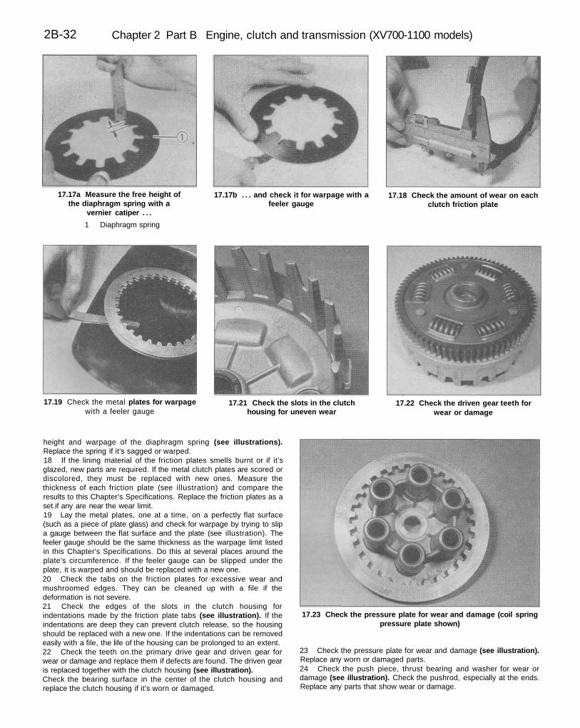
2B-32 Chapter 2 Part B Engine, clutch and transmission (XV700-1100 models)
17.17a Measure the free height ofthe diaphragm spring with a
vernier catiper . . .
1 Diaphragm spring
17.17b . . . and check it for warpage with afeeler gauge
17.18 Check the amount of wear on eachclutch friction plate
17.19 Check the metal plates for warpagewith a feeler gauge
17.21 Check the slots in the clutchhousing for uneven wear
17.22 Check the driven gear teeth forwear or damage
17.23 Check the pressure plate for wear and damage (coil springpressure plate shown)
height and warpage of the diaphragm spring (see illustrations).Replace the spring if it's sagged or warped.18 If the lining material of the friction plates smells burnt or if it'sglazed, new parts are required. If the metal clutch plates are scored ordiscolored, they must be replaced with new ones. Measure thethickness of each friction plate (see illustration) and compare theresults to this Chapter's Specifications. Replace the friction plates as aset.if any are near the wear limit.19 Lay the metal plates, one at a time, on a perfectly flat surface(such as a piece of plate glass) and check for warpage by trying to slipa gauge between the flat surface and the plate (see illustration). Thefeeler gauge should be the same thickness as the warpage limit listedin this Chapter's Specifications. Do this at several places around theplate's circumference. If the feeler gauge can be slipped under theplate, it is warped and should be replaced with a new one.20 Check the tabs on the friction plates for excessive wear andmushroomed edges. They can be cleaned up with a file if thedeformation is not severe.21 Check the edges of the slots in the clutch housing forindentations made by the friction plate tabs (see illustration). If theindentations are deep they can prevent clutch release, so the housingshould be replaced with a new one. If the indentations can be removedeasily with a file, the life of the housing can be prolonged to an extent.22 Check the teeth on.the primary drive gear and driven gear forwear or damage and replace them if defects are found. The driven gearis replaced together with the clutch housing (see illustration).Check the bearing surface in the center of the clutch housing andreplace the clutch housing if it's worn or damaged.
23 Check the pressure plate for wear and damage (see illustration).Replace any worn or damaged parts.24 Check the push piece, thrust bearing and washer for wear ordamage (see illustration). Check the pushrod, especially at the ends.Replace any parts that show wear or damage.
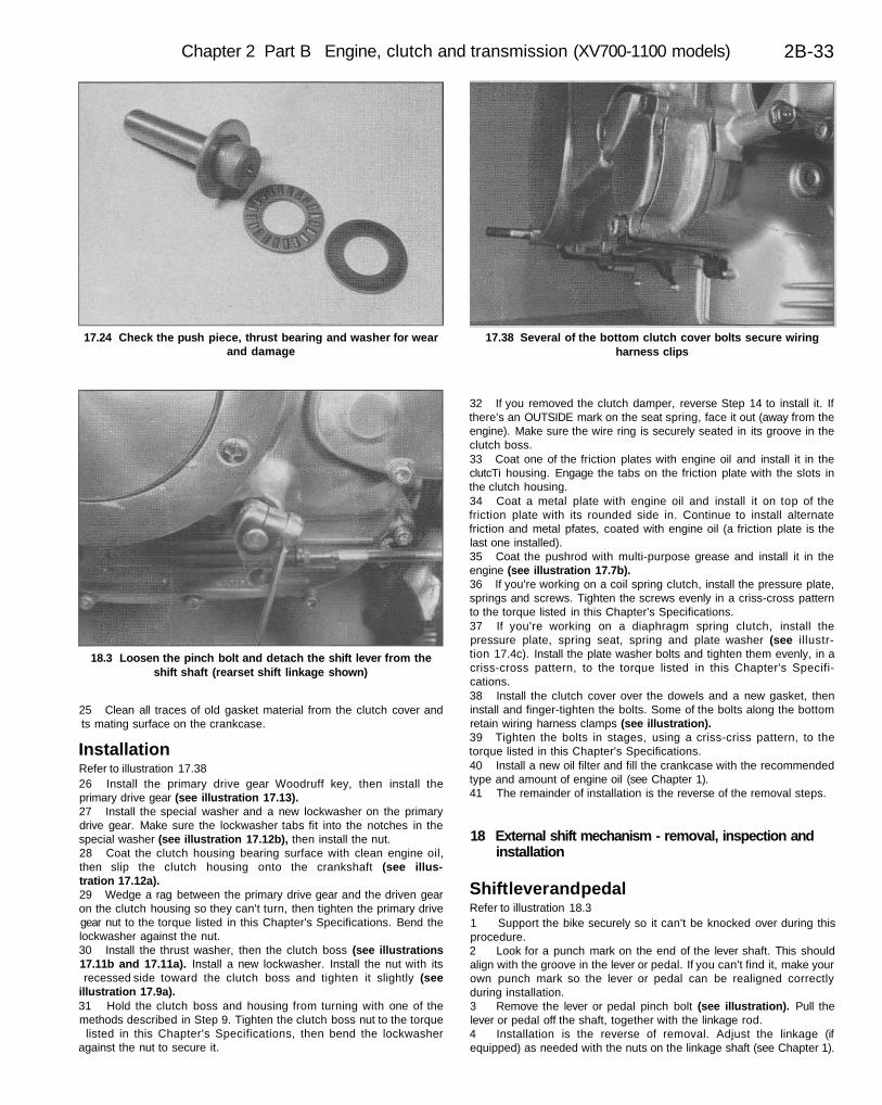
Chapter 2 Part B Engine, clutch and transmission (XV700-1100 models) 2B-33
17.24 Check the push piece, thrust bearing and washer for wearand damage
17.38 Several of the bottom clutch cover bolts secure wiringharness clips
18.3 Loosen the pinch bolt and detach the shift lever from theshift shaft (rearset shift linkage shown)
25 Clean all traces of old gasket material from the clutch cover andts mating surface on the crankcase.
InstallationRefer to illustration 17.3826 Install the primary drive gear Woodruff key, then install theprimary drive gear (see illustration 17.13).27 Install the special washer and a new lockwasher on the primarydrive gear. Make sure the lockwasher tabs fit into the notches in thespecial washer (see illustration 17.12b), then install the nut.28 Coat the clutch housing bearing surface with clean engine oil,then slip the clutch housing onto the crankshaft (see illus-tration 17.12a).29 Wedge a rag between the primary drive gear and the driven gearon the clutch housing so they can't turn, then tighten the primary drivegear nut to the torque listed in this Chapter's Specifications. Bend thelockwasher against the nut.30 Install the thrust washer, then the clutch boss (see illustrations17.11b and 17.11a). Install a new lockwasher. Install the nut with itsrecessed side toward the clutch boss and tighten it slightly (see
illustration 17.9a).31 Hold the clutch boss and housing from turning with one of themethods described in Step 9. Tighten the clutch boss nut to the torque
listed in this Chapter's Specifications, then bend the lockwasheragainst the nut to secure it.
32 If you removed the clutch damper, reverse Step 14 to install it. Ifthere's an OUTSIDE mark on the seat spring, face it out (away from theengine). Make sure the wire ring is securely seated in its groove in theclutch boss.33 Coat one of the friction plates with engine oil and install it in theclutcTi housing. Engage the tabs on the friction plate with the slots inthe clutch housing.34 Coat a metal plate with engine oil and install it on top of thefriction plate with its rounded side in. Continue to install alternatefriction and metal pfates, coated with engine oil (a friction plate is thelast one installed).35 Coat the pushrod with multi-purpose grease and install it in theengine (see illustration 17.7b).36 If you're working on a coil spring clutch, install the pressure plate,springs and screws. Tighten the screws evenly in a criss-cross patternto the torque listed in this Chapter's Specifications.37 If you're working on a diaphragm spring clutch, install thepressure plate, spring seat, spring and plate washer (see illustr-tion 17.4c). Install the plate washer bolts and tighten them evenly, in acriss-cross pattern, to the torque listed in this Chapter's Specifi-cations.38 Install the clutch cover over the dowels and a new gasket, theninstall and finger-tighten the bolts. Some of the bolts along the bottomretain wiring harness clamps (see illustration).39 Tighten the bolts in stages, using a criss-criss pattern, to thetorque listed in this Chapter's Specifications.40 Install a new oil filter and fill the crankcase with the recommendedtype and amount of engine oil (see Chapter 1).41 The remainder of installation is the reverse of the removal steps.
18 External shift mechanism - removal, inspection andinstallation
Shift lever and pedalRefer to illustration 18.31 Support the bike securely so it can't be knocked over during thisprocedure.2 Look for a punch mark on the end of the lever shaft. This shouldalign with the groove in the lever or pedal. If you can't find it, make yourown punch mark so the lever or pedal can be realigned correctlyduring installation.3 Remove the lever or pedal pinch bolt (see illustration). Pull thelever or pedal off the shaft, together with the linkage rod.4 Installation is the reverse of removal. Adjust the linkage (ifequipped) as needed with the nuts on the linkage shaft (see Chapter 1).