Embed Size (px)
Citation preview
22
Chapter 2
OPTICAL COUPLERS AND SPLITTERS
“An optical coupler takes traffic from an input port or connection and directs it, over a fabric, to
an output port. Existing electronic couplers handle variable-length packets, fixed-length cells,
and synchronous time slots to perform these operations. An optical coupler, on the other hand,
works with light and is used to direct a single wavelength, or perhaps a range of wavelengths,
from input port to output port. The all-optical couplers and splitters are more recent
development. These are all-analog device, where both the input/output modules and the
backplane are optical ones. The primary benefit of all-optical devices may be their greater
scalability over electronic devices”.
“In fact, all-optical coupling and splitting structures are completely bit-rate and protocol
transparent. It has to be realized, that most of the technologies of the all-optical coupling devices
are still emerging and usually exist in a sub-optimal form with use of amplification rather than
regeneration to boost signals during the switching. All optical coupler can be utilized to
disconnect, bypass and reroute fiber optic communications. This chapter gives introductory
detail for different types of all optical couplers and their principle of operations, followed by a
23
brief discussion on popular architectures/structures proposed in past to build higher order
coupling matrix using an elementary coupler structure”.
2.1 FUNDAMENTALS OF OPTICAL COUPLERS AND SPLITTERS
In chapter 1, it is explained that in a fiber optic data link, two stage conversion i.e. electric – to –
optical and optical – to – electrical besides transmission of optical information through the
optical fiber is a requisite operation. In this chapter, description of optical power transmission via
the optical fiber and various requisite optical operations such as switching, coupling and splitting
are discussed in brief. This chapter also describes launching of optical power through an optical
source and coupling of the same on to a adjacent fiber. The type and behavioral characteristic of
optical power transmission between fibers is important to define basic operating principle of an
all optical devices. In this chapter, it has also been explained that how transfer of optical power
from one component to another takes place between the fiber optic connections.
As compared to the point to point data link, designing a fiber optic data link is complex and
requires utmost care for its best use and compatibility with other kind of networks. Such optical
data links includes variety of devices/components like splices, switches, couplers, etc. In
permanently connected optical links, splices are used to join the optical fibers tightly. In general,
two types of splices namely mechanical splices and fusion splices are used to make a permanent
joint between the fibers.
24
However, for easy coupling and uncoupling of optical fibers, reconfigurable connectors
resembled to electrical plugs and sockets are mostly used these days. On the same way, the
optical couplers are used to couple optical power from one fiber to other fibers or many fibers.
During connection between two fibers, alignment of connected fibers with each other needs to be
taken care of in a serious manner to avoid alignment generated coupling losses. Other reason for
coupling losses between the fibers is difference of their optical properties. These properties may
include difference in the numerical apertures, core and cladding diameters, and refractive index
profiles. Similarly fiber optic coupler is used for redistribution of optical signals. That means, it
can distribute the optical signal (power) from one fiber among two or more fibers. On the other
hand, the fiber optic coupler is also used for combining the optical power from two or more
fibers on to a single fiber. In comparison of typical connector or splice, fiber optic couplers
attenuate the signal much more. Based on the working principle, the optical couplers can be
classified as active and passive couplers, splitters, combiners, X couplers, star couplers, and tree
couplers.
2.1.1 Fiber Optic and Waveguide Couplers
In splitting function, the fiber optic coupler split the input signal in two or more outputs. Such
types of couplers are known as optical splitters. On the other hand, optical combiners are used to
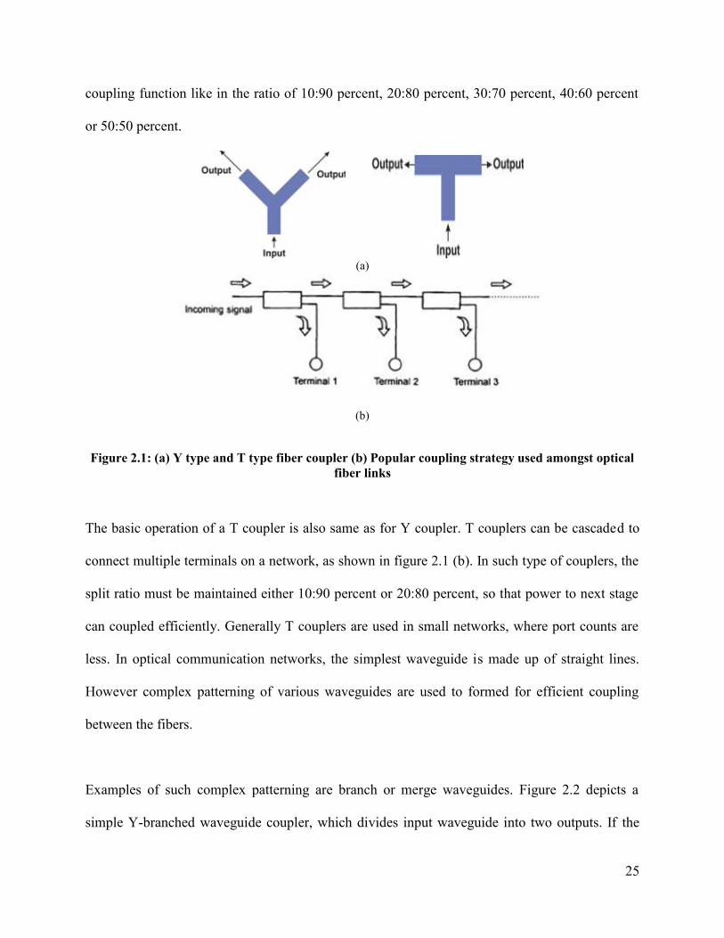
combine two or more inputs into one single output. Fiber optic coupler can be classified as Y
couplers and T couplers and are depicted in the figure 2.1. Y type of coupler is also called
optical tap coupler. Such couplers are used to divide the power in to two outputs. However
power distribution ratio has to control precisely in order to generate user or application specific
25
coupling function like in the ratio of 10:90 percent, 20:80 percent, 30:70 percent, 40:60 percent
or 50:50 percent.
(a)
(b)
Figure 2.1: (a) Y type and T type fiber coupler (b) Popular coupling strategy used amongst opticalfiber links
The basic operation of a T coupler is also same as for Y coupler. T couplers can be cascaded to
connect multiple terminals on a network, as shown in figure 2.1 (b). In such type of couplers, the
split ratio must be maintained either 10:90 percent or 20:80 percent, so that power to next stage
can coupled efficiently. Generally T couplers are used in small networks, where port counts are
less. In optical communication networks, the simplest waveguide is made up of straight lines.
However complex patterning of various waveguides are used to formed for efficient coupling
between the fibers.
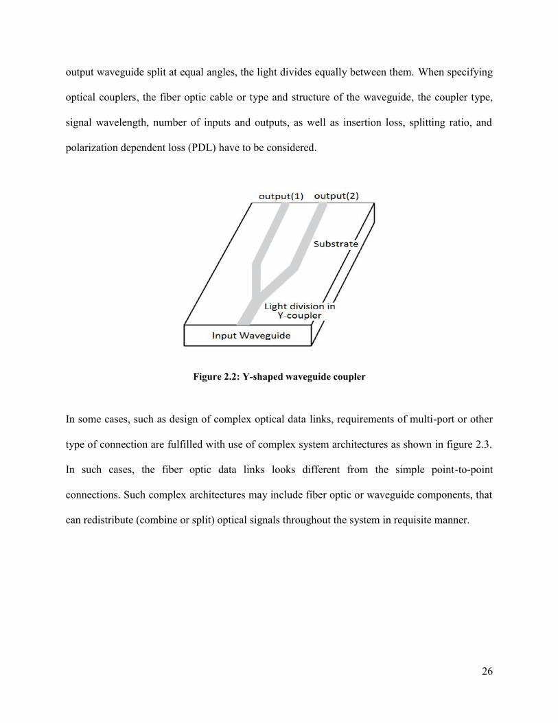
Examples of such complex patterning are branch or merge waveguides. Figure 2.2 depicts a
simple Y-branched waveguide coupler, which divides input waveguide into two outputs. If the
26
output waveguide split at equal angles, the light divides equally between them. When specifying
optical couplers, the fiber optic cable or type and structure of the waveguide, the coupler type,
signal wavelength, number of inputs and outputs, as well as insertion loss, splitting ratio, and
polarization dependent loss (PDL) have to be considered.
Figure 2.2: Y-shaped waveguide coupler
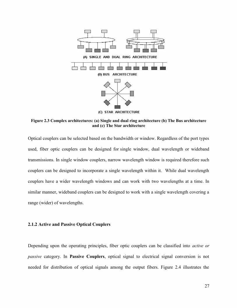
In some cases, such as design of complex optical data links, requirements of multi-port or other
type of connection are fulfilled with use of complex system architectures as shown in figure 2.3.
In such cases, the fiber optic data links looks different from the simple point-to-point
connections. Such complex architectures may include fiber optic or waveguide components, that
can redistribute (combine or split) optical signals throughout the system in requisite manner.
27
Figure 2.3 Complex architectures: (a) Single and dual ring architecture (b) The Bus architectureand (c) The Star architecture
Optical couplers can be selected based on the bandwidth or window. Regardless of the port types
used, fiber optic couplers can be designed for single window, dual wavelength or wideband
transmissions. In single window couplers, narrow wavelength window is required therefore such
couplers can be designed to incorporate a single wavelength within it. While dual wavelength
couplers have a wider wavelength windows and can work with two wavelengths at a time. In
similar manner, wideband couplers can be designed to work with a single wavelength covering a
range (wider) of wavelengths.
2.1.2 Active and Passive Optical Couplers
Depending upon the operating principles, fiber optic couplers can be classified into active or
passive category. In Passive Couplers, optical signal to electrical signal conversion is not
needed for distribution of optical signals among the output fibers. Figure 2.4 illustrates the

28
schematic of a passive fiber optic coupler. Typically it consist of N input ports and M output
ports, where value of N and M ranges from 1 to 64. The selection of number of input ports and
output ports depends upon its uses, i.e. applications in which passive couplers has to used.
In generic passive couplers, micro-lenses, graded-refractive-index (GRIN) rods, beam splitters,
optical mixers, splices and the optical fibers with fused core are used. That is why; fabricating
the passive fiber optic coupler is difficult and requires cumbersome process. On the other hand,
Active Couplers split or combine the signal electrically and use optical detectors and sources for
input and output. Therefore active fiber optic couplers require an external power source. They
receive input signal(s), and then use a combination of fiber optic detectors, optical-to-electrical
converters, and light sources to transmit fiber optic signals.
Figure 2.4: Schematic of a passive fiber optic coupler
2.1.3 Optical Splitter and Combiner
An optical splitter is also a passive device, which is used to divide the optical power and transmit
to two adjacent fibers as shown in figure 2.5. In deal case, the splitter divides the optical power
into two equal parts among the fibers. Figure 2.5 depicts a Y branched splitter. Also it can be
used to divide the incident optical power into unequal powers depending upon the structuring of
29
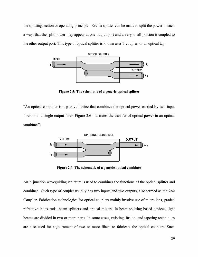
the splitting section or operating principle. Even a splitter can be made to split the power in such
a way, that the split power may appear at one output port and a very small portion it coupled to
the other output port. This type of optical splitter is known as a T-coupler, or an optical tap.
Figure 2.5: The schematic of a generic optical splitter
“An optical combiner is a passive device that combines the optical power carried by two input
fibers into a single output fiber. Figure 2.6 illustrates the transfer of optical power in an optical
combiner”.
Figure 2.6: The schematic of a generic optical combiner
An X junction waveguiding structure is used to combines the functions of the optical splitter and
combiner. Such type of coupler usually has two inputs and two outputs, also termed as the 2×2
Coupler. Fabrication technologies for optical couplers mainly involve use of micro lens, graded
refractive index rods, beam splitters and optical mixers. In beam splitting based devices, light
beams are divided in two or more parts. In some cases, twisting, fusion, and tapering techniques
are also used for adjournment of two or more fibers to fabricate the optical couplers. Such

30
techniques are popularly used to fabricate the fused Biconical taper couplers, in which beam
splitting is accomplish by radiative coupling of light from the input fiber to the output fibers in
the tapered region.
2.1.4 Star and Tree couplers
These are examples of multiport couplers consisting of two or more input output port
combinations. A star coupler generally has several input and output port combination, in which
the optical power is distributed from more than two input ports among several output ports. The
number of input and output port may or may not be equal in star couplers such as 2×4, 4×4,
8×16, etc. However in all possible input and output port combinations, the distribution of power
among the output ports remains equal.
A star coupler can further classified as Directional and Non-directional star coupler. Figure 2.7
depicts a directional type star coupler, in which initially mixing of all input signal is done and
then the collected power is equally transferred to the output ports. If the transmission in a star
coupler is possible in both directions, then they can be further classified as bidirectional coupling
devices.

31
Figure 2.7: Star coupler (Directional type)
While in a non-directional type of star coupling device, a signal applied to any fiber appears at
all other remaining fibers as shown in figure 2.8 (a). With use of reflective mirrors, such couplers
can be used to work as directional reflective star couplers as shown in figure 2.8 (b).
(a) (b)
Figure 2.8: (a) Non-directional Star coupler (b) Directional reflective type Star coupler
Figure 2.9 depicts examples of another type of passive couplers, known as tree couplers.
Depending upon the number of input and outputs, tree coupler is used to splits or combines the
optical power from input fibers to output fibers. Star and tree couplers distribute the input power
uniformly among the output fibers.

32
Figure 2.9: Schematic of 1xM and Nx1 Tree couplers
During operation it is desirable that fiber optic couplers should transfer (coupled) the optical
power to the desired output fiber only and should by pass all other (undesired) output fibers.
Directional couplers are better known for transfer of optical through coupling mechanism in such
manner. Depending upon the capability, the couplers can be categorizing as Symmetrical and
Unsymmetrical couplers. In symmetrical couplers, transfer of equal amount of optical power is
possible even if the input and output ports are changed with each other, i.e. for reverse operation,
the coupling efficiency remain same. “Tree couplers have been extensively used to split and mix
optical signals in CATV, LANs and all other kinds of optical communication systems”. For
higher port networks (requiring more than 3 or 4 terminals), star couplers are better to use in
place of cascaded T coupler, as they possess lower excess losses as compared to T couplers for
similar kind of operation.

33
2.2 POPULAR FABRICATION CRITERION FOR COUPLERS AND SPLITTERS
Depending upon the size, shape and application area, technologies for fabricating of optical
couplers and splitter may vary. The fabrication of such optical devices are also depends upon
their principle of operations and allowable tolerances. Some of popular fabrication technologies
are as follows.
2.2.1 Fused or Biconical Taper Coupler
In a most common fused coupler technology, the claddings of two or more fibers are partially
removed and the fibers are placed in close proximity shown in figure 2.10 over some length so
that propagating light can couples from one fiber into the others. The coupling efficiency of such
couplers can be maintained by the thickness of the remaining cladding and the proximity length.
Figure 2.10: Fabrication steps for fused couplers
After exposing the cladding of many fibers to an applied tension, this type of couplers are
fabricated by heating the junction area. The amount and the length of the coupling region depend

34
upon the amount of tension and the heating time. This method has been used to fabricate all sort
of couplers such as T coupler, Tree coupler and the Star coupler. However the operation of a
fused coupler is also depends upon the fibers used to fabricate it, i.e. whether the fibers used are
of single mode nature or support the multimode. “That is why multimode couplers useful for
WDM application cannot be made using fused fibers, as in their operation, the higher-order
modes leak into the cladding and into the core of the other fiber as well”.
“The degree of coupling depends on the length of the coupling zone, and does not depend on
wavelength. Also in adjacent single mode fibers, coupling between their cores take place due to
resonant interaction, which depend upon the length of interaction. Also after the interaction, the
transferred light return back to the original fibers, if the interaction take place further up to the
same interaction period. In this way single mode WDM couplers can be made, in which the
cycling of light transfer majorly depends upon the coupler design (i.e. interaction length) and the
operating wavelength”.
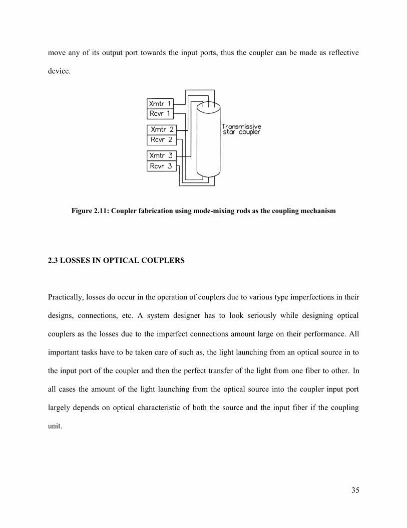
2.2.2 Realization of Coupling Mechanism Using the Mode-Mixing Rods
In this technique, a mode mixing rod made up of Glass of few mm diameters is used to transfer
the light from all input ports to the end ports. The coupling mechanism in such type of coupler
also depends upon the interaction length between the mode mixing rods and the input light from
various input ports. Also in mode mixing rod couplers, transmission of light is uniformly taking
place among the output fibers. Reflecting mirror surfaces can also be used in such couplers to
35
move any of its output port towards the input ports, thus the coupler can be made as reflective
device.
Figure 2.11: Coupler fabrication using mode-mixing rods as the coupling mechanism
2.3 LOSSES IN OPTICAL COUPLERS
Practically, losses do occur in the operation of couplers due to various type imperfections in their
designs, connections, etc. A system designer has to look seriously while designing optical
couplers as the losses due to the imperfect connections amount large on their performance. All
important tasks have to be taken care of such as, the light launching from an optical source in to
the input port of the coupler and then the perfect transfer of the light from one fiber to other. In
all cases the amount of the light launching from the optical source into the coupler input port
largely depends on optical characteristic of both the source and the input fiber if the coupling
unit.

36
“Radiance of an optical source does have a major impact on the amount of optical power that can
be launched into an optical fiber. The radiance or the brightness of an optical source depicts its
capability of launching optical power. Radiance is the amount of optical power emitted in a
specific direction per unit time by a unit area of emitting surface. In most cases, only a small
portion of the launched power from an optical source actually enters into the input fiber, while
rest of power lost somewhere in between them”. The loss in optical power through a connection
is defined as:
Loss = 10log10 (Pi/Po) ………………………………………………………..………………(2.1)
“For example, Po is the power emitted from the source fiber in a fiber-to-fiber connection. Pi is
the power accepted by the connected fiber. In any fiber optic connection, Po and Pi are the optical
power levels measured before and after the joint, respectively”.
2.3.1 Intrinsic and extrinsic coupling losses
In optical networks, fiber to fiber joints are important to transfer the information from one point
to other, however in the process optical losses take places due to various reasons. One important
reason is optical coupling loses between the fiber to fiber joints; such losses can be categorized
in to intrinsic and extrinsic losses. Among the fiber to fiber connections, intrinsic losses take
places due to the mismatch in fiber properties, while the extrinsic losses are caused by techniques
used to join the fibers. Therefore intrinsic losses can be reduced or avoid by matching the fiber
characteristics in terms of geometrical and optical properties of the fibers to be connected with
37
each other. On the other hand, extrinsic losses can be suppressed by proper connecting patterns
between the fibers.
In some cases modular devices are used to avoid such type of connecting losses, for examples
most of optical networks and circuits provided with transmitters and receivers, which are used as
modular components. Modular components such as transmitters and receivers are popularly
made up of pigtails or fiber optic connectors. Made up of short length of about 1 meter or less, a
fiber pigtail is an optical fiber, which is fixed with the optical source or detector permanently. In
general, fabricators work with “transmitters and receivers with pigtails and connectors, as the
fiber coupling with the sources and detectors needs to be completed during fabrication. If the
manufacturing process is controlled actively, then the source-to-fiber and fiber-to-detector
coupling can be achieved with reduced coupling” losses.
2.3.2 Reflection losses
In most cases, optical power gets reflected back towards the fiber, where from it is originating
and lost in actual. This type of loss is known as Reflection loss or Fresnel reflection losses. Such
losses may occur at each and every improper fiber interface. The Fresnel reflective losses are
caused by the variation in the refractive index at the fiber joints. In most cases, variations in the
refractive index is of the nature of step like change, which is caused by the ends of each fiber
being separated by a small gap (usually air). The Fresnel reflection ratio (R) as shown below can
be used to estimate the portion of incident light (light of normal incidence), which reflected back
into the source fiber.

38
……………………………………………………………………..…………(2.2)
In equation 2.2, n1 is the refractive index of the core of the fiber, while n0 represent the refractive
index of the medium in between fibers. In general, reflection of light signals through Fresnel
effect occurs two times, while propagating through the fiber to fiber connection. Initially, the
optical power gets reflected back once it enters in to the first fiber from the source and there after
the successive reflection took place at the interconnection of the fibers, i.e. when the light enters
at the receiving fiber. The total fiber to fiber coupling loss can be calculated by taking the
Fresnel reflection at each interface into account.
Optical losses caused by the Fresnel reflection are significant and needs to suppress by means of
designing the fibers in such a way that frequent variations in the indices can be avoided. In most
cases, index matching gel are used to filled the air gaps to minimize the amount of loss from
Fresnel reflection. As once the connection between the fibers made, it is fixed for thought out
their application and should not require maintenance, and therefore the choice of index matching
gels is important. The index matching liquid or gel is chosen in such a way that it should satisfy
the optical and mechanical specifications over the lifetime of the fiber connections and thereby it
should also remain transparent. Such gels have to be capable to avoid flowing or dripping by
remaining viscous. However it has been observed that many index matching gels get darken and
some settle or leak out of fiber connections over a period of time. The fiber to fiber connection
losses increases with their period of operation, if such requirements are matched with the

39
standard ones. Therefore in some applications, for example, index matching gels are being used
at joints of optical splices as variations in connection losses over the time is undesirable in Navy
applications.
2.3.3 Other important performance parameters of an optical coupler
“There are many important parameters which can be used to characterize suitability of an optical
coupler for optical networks. The most important” parameters of an optical coupler are coupling
efficiency and the response time. Different applications require different power coupling
requirements.
Insertion Loss: Fiber optic components disrupt signal transmissions as the continuous core of
the optical fiber carrying the signal mates with the component in a manner that causes some
amount of scattering and reflection of light waves. The degree to which the signal has been
depleted is described as insertion loss, which is the undesired attenuation of the signal measured
in decibels (dB).
Splitting Ratio: The “splitting ratio is the distribution of power among the output fibers of a
coupler, it is also referred to as the coupling ratio. A splitting ratio of 50/50 means that there is
an equal distribution of optical power”; a 60/40 ratio means 60% of the power is transmitted to a
primary output and 40% to the secondary output.
Polarization Dependent Loss (PDL): The polarization dependent losses are defined as the
attenuation caused by polarization. “There are other types of losses that are incurred during
40
optical coupling and may influence the device performance, like reflectance or return loss,
directivity, isolation factor etc. Other parameters that can also be taken into account include
scalability, reliability, energy (power) usage and temperature resistance [1]. The term scalability
refers to the ability to integrate several smaller (1×2, 2×2) couplers into a large coupling matrix
(1×N, N×N, etc.). It is particularly an important concern”.
Reliability: It is another important issue, which relates the lifetime operation of the couplers
within acceptable performance. “The losses discussed above do not represent all sort of losses
incurred during optical coupling phenomena, as many losses also take place within the coupling
structure due to signal attenuation, scattering, improper design and fabrication losses. Material
dependent absorption losses and improper doping level in the base material also makes a
contribution in degrading their performance”.
2.4 CHAPTER SUMMARY
Optical couplers, splitters, and combiners “can be classified with many criteria like with the port
counts (1×2, 2×2, 4×4, 16×16 switches etc.), their principle of operation (Self-imaging,
plasmonic, micro–mirror based couplers, etc.) and according to the coupling medium (waveguide
or fiber based). In this chapter, some popular coupling structures, their types, applications and
limitations have been covered. When specifying optical couplers, the fiber optic cable, the
coupler type, signal wavelength, number of inputs and outputs, as well as insertion loss, splitting
ratio, and polarization dependent loss (PDL) have to be considered. While designing higher order
couplers, many performance aspects such as area coverage, power requirements, low loss
41
operations are” needed to be explored with respect to connection pattern of small switches. “A
flexible architecture is always preferred in order to implement new path without making much
modifications in basic patterns, so as to maintain the cost and area coverage constraints.
Furthermore, a suitable connection pattern leads to effectively use of the same design and
fabricate couplers with higher port counts within the loss, fabrication tolerance and time response
constraints. Optical couplers can be specified by the number of ports used for signal
transmissions going in as well as out. The number and type of ports can be used to describe
whether the device is in a splitter, combiner, X-coupler, star or tree coupler”.