Embed Size (px)
Citation preview

I. Intent (20.78-2.I) The purpose of this Chapter is to ensure the successful integration of safe, well-designed, and attractive non-residential development into the community. Such development should be designed in context with adjacent uses and sensitive to environmental resources. Such areas typically enjoy high visibility or serve as employment destinations. The community image is further enhanced by designs that exhibit exceptional quality, identity, and interest.
A. Applicability (20-78-2.I.A)
1. Non-residential development for new construction, excluding interior Tenant Improvements.
2. Alterations to the exterior façade of an existing building and/or suite/storefront including significant color or material changes or the use of exposed neon lighting.
B. Exemptions (20-78-2.I.B)
1. Interior alterations that combine one or more suite/storefront shall not be considered new construction or a new construction addition.
2. Cabinet or pan channel sign changes shall not constitute alterations under this section.
3. The following uses shall be held exempt from Design Review but are subject to evaluation of walls, colors, screening and context:
a. Monopoles or other wireless communication
Chapter 2: Non Residential Development
NR-1
Administration
Non-Residential
Single-Family
Multi-Family
Specific Areas
facilities.
b. Utility substations.
c. Accessory fabric canopy structures (i.e. car wash canopies).
d. Mini-storage facilities, excluding accessory offices and any visible facades.
II. Site Design (20-78-2.II)
A. Site Layout and Orientation (20-78-2.II.A)
1. The site should integrate natural features into the development template such as topography, prominent view corridors, washes, and significant vegetative stands to enhance the character of the development.
2. Building placement and orientation along the street shall be staggered, angled, or curved to provide modulation and interest. Angled or sculpted building corners and/or an open plaza are encouraged at corner locations. (Figure 2.1)
3. Dated “L” shaped suburban shopping centers should be avoided. Clusters of smaller buildings with pad buildings at the street edge are strongly encouraged. (Figure 2.2)
4. Where appropriate, buildings and uses should be integrated with public spaces and planned active recreational amenities. (Figure 2.3)
5. Driveway access points and internal circulation should be located as far away as possible from residential properties, schools, parks, and other sensitive uses.
NR-2
Figure 2.3—The buildings and public spaces are complementary and foster community interaction.
Figure 2.2—Strong corner orientation minimizes view of parking fields.
Figure 2.1—A sculpted building corner adds visual interest.
6. The development shall be designed to facilitate the efficient use of energy through building orientation, window and door placement, landscaping, awnings, canopies, window treatment (i.e. glazing), and other appropriate design solutions.
7. Drainage basins should not be located within the front setback unless designed as an attractive landscaped element. Stormwater retention areas shall be designed as landscape features rather than large, unadorned depressions in the site.
B. Access and Circulation (20-78-2.II.B)
1. Parking lots should be designed with a clear hierarchy of circulation, major access drives with no parking, secondary circulation drives with little or no parking, and then parking aisles for direct access to parking spaces.
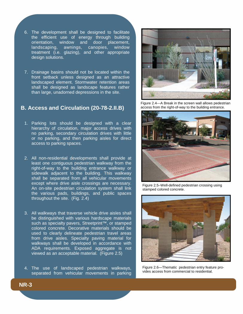
2. All non-residential developments shall provide at least one contiguous pedestrian walkway from the right-of-way to the building entrance walkway or sidewalk adjacent to the building. This walkway shall be separated from all vehicular movements except where drive aisle crossings are necessary. An on-site pedestrian circulation system shall link the various pads, buildings, and public spaces throughout the site. (Fig. 2.4)
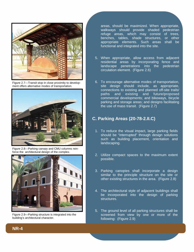
3. All walkways that traverse vehicle drive aisles shall be distinguished with various hardscape materials such as specialty pavers, Streetprint™, or stamped colored concrete. Decorative materials should be used to clearly delineate pedestrian travel areas from drive aisles. Specialty paving material for walkways shall be developed in accordance with ADA requirements. Exposed aggregate is not viewed as an acceptable material. (Figure 2.5)
4. The use of landscaped pedestrian walkways, separated from vehicular movements in parking
NR-3
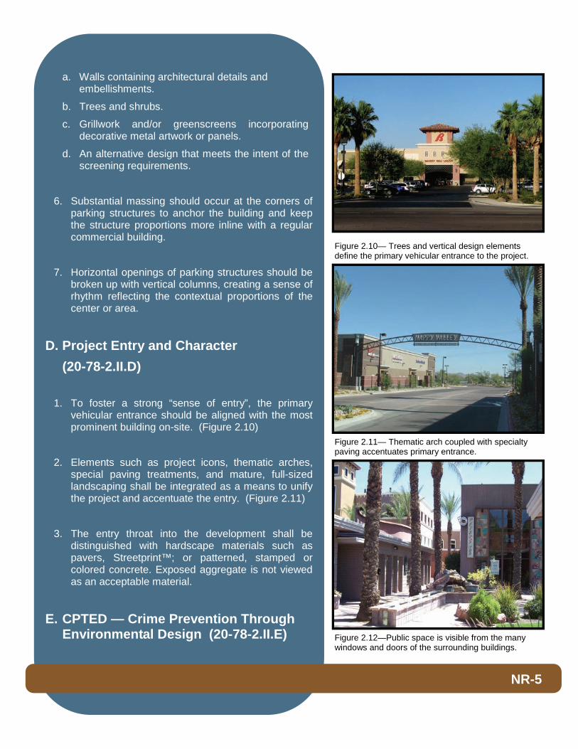
Figure 2.6—Thematic pedestrian entry feature pro-vides access from commercial to residential.
Figure 2.5–Well-defined pedestrian crossing using stamped colored concrete.
Figure 2.4—A Break in the screen wall allows pedestrian access from the right-of-way to the building entrance.
areas, should be maximized. When appropriate, walkways should provide shaded pedestrian refuge areas, which may consist of trees, benches, tables, shade structures, or other appropriate elements. Such areas shall be functional and integrated into the site.
5. When appropriate, allow access from adjacent residential areas by incorporating fence and landscape penetrations into the pedestrian circulation element. (Figure 2.6)
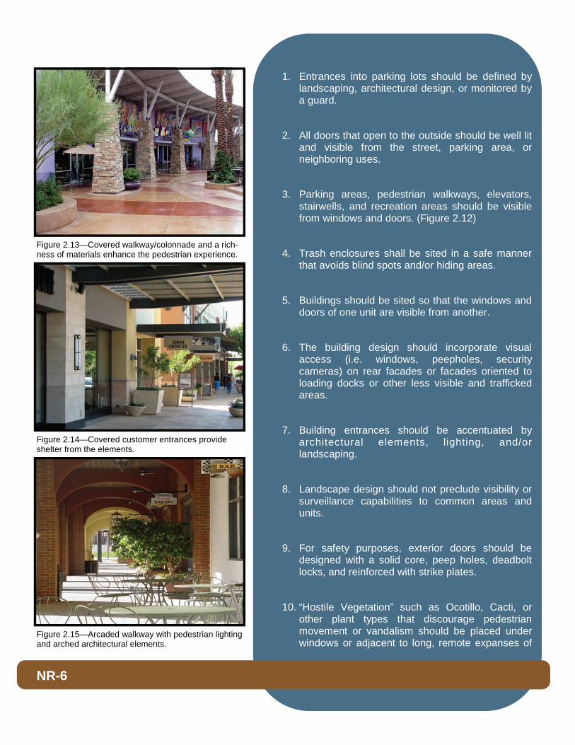
6. To encourage alternative modes of transportation, site design should include, as appropriate, connections to existing and planned off-site trails/paths and existing and future/proposed commercial developments; and bikeways, bicycle parking and storage areas; and designs facilitating the use of mass transit. (Figure 2.7)
C. Parking Areas (20-78-2.II.C)
1. To reduce the visual impact, large parking fields should be “interrupted” through design solutions such as building placement, orientation and landscaping.
2. Utilize compact spaces to the maximum extent possible.
3. Parking canopies shall incorporate a design similar to the principle structure on the site or other existing structures in the area. (Figure 2.8)
4. The architectural style of adjacent buildings shall be incorporated into the design of parking structures.
5. The ground level of all parking structures shall be screened from view by one or more of the following: (Figure 2.9)
NR-4
Figure 2.9—Parking structure is integrated into the building’s architectural character.
Figure 2.8—Parking canopy and CMU columns rein-force the architectural design of the complex.
Figure 2.7—Transit stop in close proximity to develop-ment offers alternative modes of transportation.
a. Walls containing architectural details and embellishments.
b. Trees and shrubs.
c. Grillwork and/or greenscreens incorporating decorative metal artwork or panels.
d. An alternative design that meets the intent of the screening requirements.
6. Substantial massing should occur at the corners of parking structures to anchor the building and keep the structure proportions more inline with a regular commercial building.
7. Horizontal openings of parking structures should be broken up with vertical columns, creating a sense of rhythm reflecting the contextual proportions of the center or area.
D. Project Entry and Character (20-78-2.II.D)
1. To foster a strong “sense of entry”, the primary vehicular entrance should be aligned with the most prominent building on-site. (Figure 2.10)
2. Elements such as project icons, thematic arches, special paving treatments, and mature, full-sized landscaping shall be integrated as a means to unify the project and accentuate the entry. (Figure 2.11)
3. The entry throat into the development shall be distinguished with hardscape materials such as pavers, Streetprint™; or patterned, stamped or colored concrete. Exposed aggregate is not viewed as an acceptable material.
E. CPTED — Crime Prevention Through Environmental Design (20-78-2.II.E)
NR-5
Figure 2.12—Public space is visible from the many windows and doors of the surrounding buildings.
Figure 2.11— Thematic arch coupled with specialty paving accentuates primary entrance.
Figure 2.10— Trees and vertical design elements define the primary vehicular entrance to the project.
1. Entrances into parking lots should be defined by landscaping, architectural design, or monitored by a guard.
2. All doors that open to the outside should be well lit and visible from the street, parking area, or neighboring uses.
3. Parking areas, pedestrian walkways, elevators, stairwells, and recreation areas should be visible from windows and doors. (Figure 2.12)
4. Trash enclosures shall be sited in a safe manner that avoids blind spots and/or hiding areas.
5. Buildings should be sited so that the windows and doors of one unit are visible from another.
6. The building design should incorporate visual access (i.e. windows, peepholes, security cameras) on rear facades or facades oriented to loading docks or other less visible and trafficked areas.
7. Building entrances should be accentuated by architectural elements, lighting, and/or landscaping.
8. Landscape design should not preclude visibility or surveillance capabilities to common areas and units.
9. For safety purposes, exterior doors should be designed with a solid core, peep holes, deadbolt locks, and reinforced with strike plates.
10. “Hostile Vegetation” such as Ocotillo, Cacti, or other plant types that discourage pedestrian movement or vandalism should be placed under windows or adjacent to long, remote expanses of
NR-6
Figure 2.15—Arcaded walkway with pedestrian lighting and arched architectural elements.
Figure 2.14—Covered customer entrances provide shelter from the elements.
Figure 2.13—Covered walkway/colonnade and a rich-ness of materials enhance the pedestrian experience.
perimeter walls, which are not otherwise designed as an amenity.
F. Pedestrian Amenities / Public Space
(20-78-2.II.F)
1. Site design shall incorporate elements that enhance the pedestrian environment, such as features that reflect human scale, the use of covered walkways for the shelter and shade of the pedestrian, and richness of materials at the pedestrian level. (Figures 2.13 and 2.15)
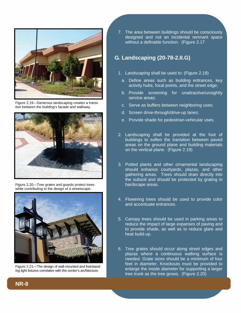
2. Customer entrances shall provide weather protection features such as awnings, arcades, or colonnades. (Figure 2.14)
3. Walkways shall be enhanced by special design features such as towers, arcades, porticos, pedestrian light features, bollards, planter walls, and other architectural elements that define circulation ways and outdoor spaces. (Figure 2.15)
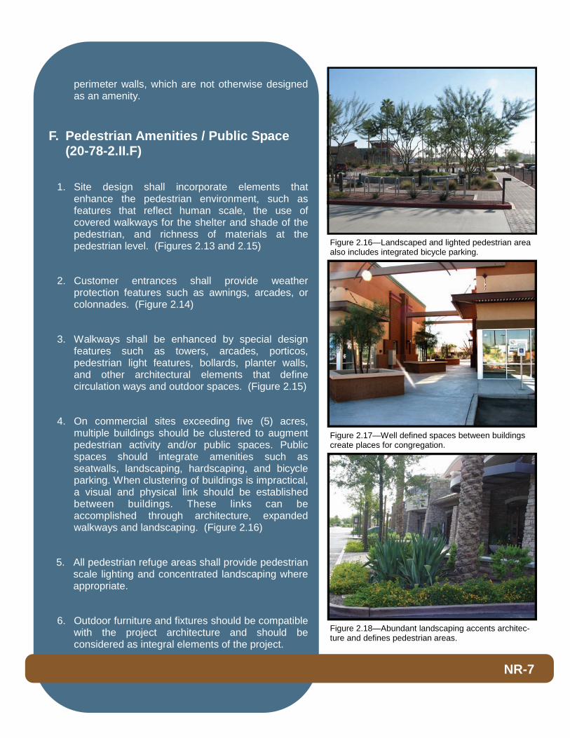
4. On commercial sites exceeding five (5) acres, multiple buildings should be clustered to augment pedestrian activity and/or public spaces. Public spaces should integrate amenities such as seatwalls, landscaping, hardscaping, and bicycle parking. When clustering of buildings is impractical, a visual and physical link should be established between buildings. These links can be accomplished through architecture, expanded walkways and landscaping. (Figure 2.16)
5. All pedestrian refuge areas shall provide pedestrian scale lighting and concentrated landscaping where appropriate.
6. Outdoor furniture and fixtures should be compatible with the project architecture and should be considered as integral elements of the project.
NR-7
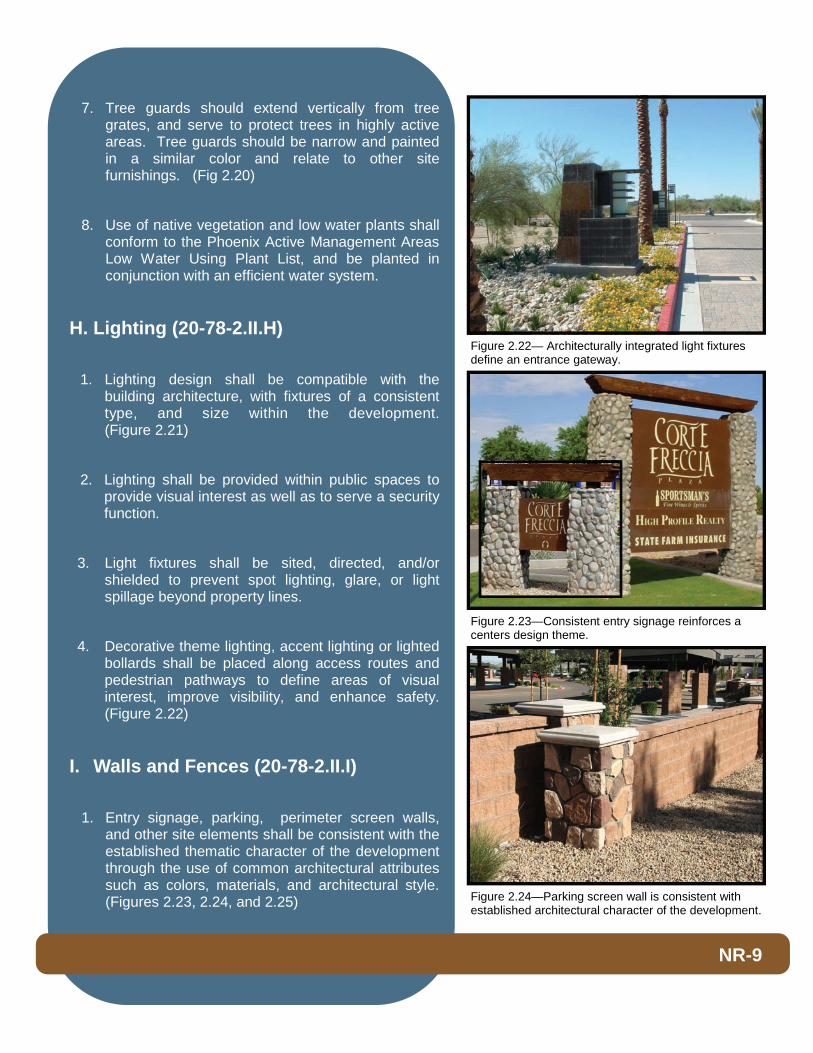
Figure 2.18—Abundant landscaping accents architec-ture and defines pedestrian areas.
Figure 2.17—Well defined spaces between buildings create places for congregation.
Figure 2.16—Landscaped and lighted pedestrian area also includes integrated bicycle parking.
7. The area between buildings should be consciously designed and not an incidental remnant space without a definable function. (Figure 2.17
G. Landscaping (20-78-2.II.G)
1. Landscaping shall be used to: (Figure 2.18)
a. Define areas such as building entrances, key activity hubs, focal points, and the street edge;
b. Provide screening for unattractive/unsightly service areas;
c. Serve as buffers between neighboring uses;
d. Screen drive-through/drive-up lanes;
e. Provide shade for pedestrian-vehicular uses.
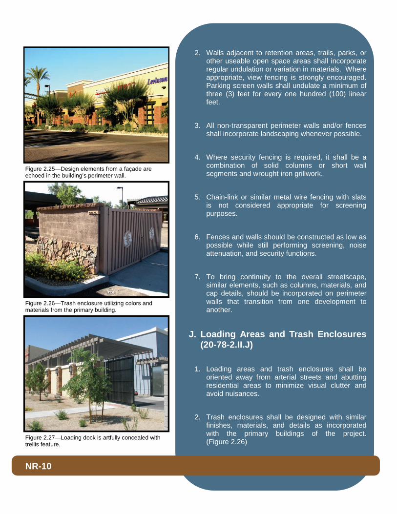
2. Landscaping shall be provided at the foot of buildings to soften the transition between paved areas on the ground plane and building materials on the vertical plane. (Figure 2.19)
3. Potted plants and other ornamental landscaping should enhance courtyards, plazas, and other gathering areas. Trees should drain directly into the subsoil and should be protected by grating in hardscape areas.
4. Flowering trees should be used to provide color and accentuate entrances.
5. Canopy trees should be used in parking areas to reduce the impact of large expanses of paving and to provide shade, as well as to reduce glare and heat build-up.
6. Tree grates should occur along street edges and plazas where a continuous walking surface is needed. Grate sizes should be a minimum of four feet in diameter. Knockouts must be provided to enlarge the inside diameter for supporting a larger tree trunk as the tree grows. (Figure 2.20)
NR-8
Figure 2.21—The design of wall-mounted and freestand-ing light fixtures correlates with the center’s architecture.
Figure 2.20—Tree grates and guards protect trees while contributing to the design of a streetscape.
Figure 2.19—Generous landscaping creates a transi-tion between the building’s facade and walkway.
7. Tree guards should extend vertically from tree grates, and serve to protect trees in highly active areas. Tree guards should be narrow and painted in a similar color and relate to other site furnishings. (Fig 2.20)
8. Use of native vegetation and low water plants shall conform to the Phoenix Active Management Areas Low Water Using Plant List, and be planted in conjunction with an efficient water system.
H. Lighting (20-78-2.II.H)
1. Lighting design shall be compatible with the building architecture, with fixtures of a consistent type, and size within the development. (Figure 2.21)
2. Lighting shall be provided within public spaces to provide visual interest as well as to serve a security function.
3. Light fixtures shall be sited, directed, and/or shielded to prevent spot lighting, glare, or light spillage beyond property lines.
4. Decorative theme lighting, accent lighting or lighted bollards shall be placed along access routes and pedestrian pathways to define areas of visual interest, improve visibility, and enhance safety. (Figure 2.22)
I. Walls and Fences (20-78-2.II.I)
1. Entry signage, parking, perimeter screen walls, and other site elements shall be consistent with the established thematic character of the development through the use of common architectural attributes such as colors, materials, and architectural style. (Figures 2.23, 2.24, and 2.25)
NR-9
Figure 2.22— Architecturally integrated light fixtures define an entrance gateway.
Figure 2.24—Parking screen wall is consistent with established architectural character of the development.
Figure 2.23—Consistent entry signage reinforces a centers design theme.
2. Walls adjacent to retention areas, trails, parks, or other useable open space areas shall incorporate regular undulation or variation in materials. Where appropriate, view fencing is strongly encouraged. Parking screen walls shall undulate a minimum of three (3) feet for every one hundred (100) linear feet.
3. All non-transparent perimeter walls and/or fences shall incorporate landscaping whenever possible.
4. Where security fencing is required, it shall be a combination of solid columns or short wall segments and wrought iron grillwork.
5. Chain-link or similar metal wire fencing with slats is not considered appropriate for screening purposes.
6. Fences and walls should be constructed as low as possible while still performing screening, noise attenuation, and security functions.
7. To bring continuity to the overall streetscape, similar elements, such as columns, materials, and cap details, should be incorporated on perimeter walls that transition from one development to another.
J. Loading Areas and Trash Enclosures (20-78-2.II.J)
1. Loading areas and trash enclosures shall be oriented away from arterial streets and abutting residential areas to minimize visual clutter and avoid nuisances.
2. Trash enclosures shall be designed with similar finishes, materials, and details as incorporated with the primary buildings of the project. (Figure 2.26)
NR-10
Figure 2.26—Trash enclosure utilizing colors and materials from the primary building.
Figure 2.25—Design elements from a façade are echoed in the building’s perimeter wall.
Figure 2.27—Loading dock is artfully concealed with trellis feature.

3. Trash enclosure locations shall be placed in proximate locations for tenant convenience and pickup service.
4. Trash enclosure locations shall not hinder internal traffic circulation visibility.
5. Loading docks shall be screened from view utilizing design solutions including, but not limited to, decorative walls, trellis/greenscreens, berming, dense landscaping, or a combination thereof.(Figure 2.27)
6. Public circulation should not route through loading and service areas.
7. If visible from public-view, roll-up doors are discouraged; however, where such doors occur, the doors should be recessed a minimum of twelve (12) inches into the building to provide a shadow line.
8. Service and roll-up doors shall be painted to match the building or trim colors.
K. Utilities and Mechanical Equipment (20-78-2.II.K)
1. Noise generating equipment should be located away from residential units, public spaces, and pedestrian areas.
2. Backflow preventers for landscape irrigation and domestic water shall not be located at visually prominent locations and shall be well-screened with shrubs, berming, or low-screen walls.
3. Roof access ladders and roof drains/downspouts shall be internalized within the building.
NR-11
Figure 2.29—Bicycle racks are incorporated into overall thematic site design.
Figure 2.28—A fountain distinguishes the entrance to a retail center.
Figure 2.30—Congregation areas are defined by the use of bollards.
4. Ground and roof mounted mechanical equipment shall be screened from public view (street-level).
5. Utility screening requirements, including Service Entrance Sections, are located in Chapter 5 Supplementary Standards.
L. Other Thematic Elements (20-78-2.II.L)
1. Visual features, such as fountains, should be incorporated into commercial developments to attract pedestrians. Where a large number of children may be present, pop-jet fountains should be considered. (Figure 2.28)
2. Drainage crossings shall utilize decorative railings consistent with the thematic character of the complex. The determination whether a railing is warranted for a specific crossing shall be made by the City Engineer or designee.
3. The design of any outdoor storage or garden facilities shall complement the architecture of the primary building as well as the overall site design.
4. Bicycle racks should be selected that are durable and visually appealing. (Figure 2.29)
5. In the event that bollards are warranted to separate pedestrian and/or public spaces from circulation routes, said bollards shall complement the architectural style of the center. Corporate colors applied to the bollards are expressly discouraged. (Figure 2.30)
III. Architectural Form (20-78-2.III)
A. Design Theme (20-78-2.III.A)
NR-12
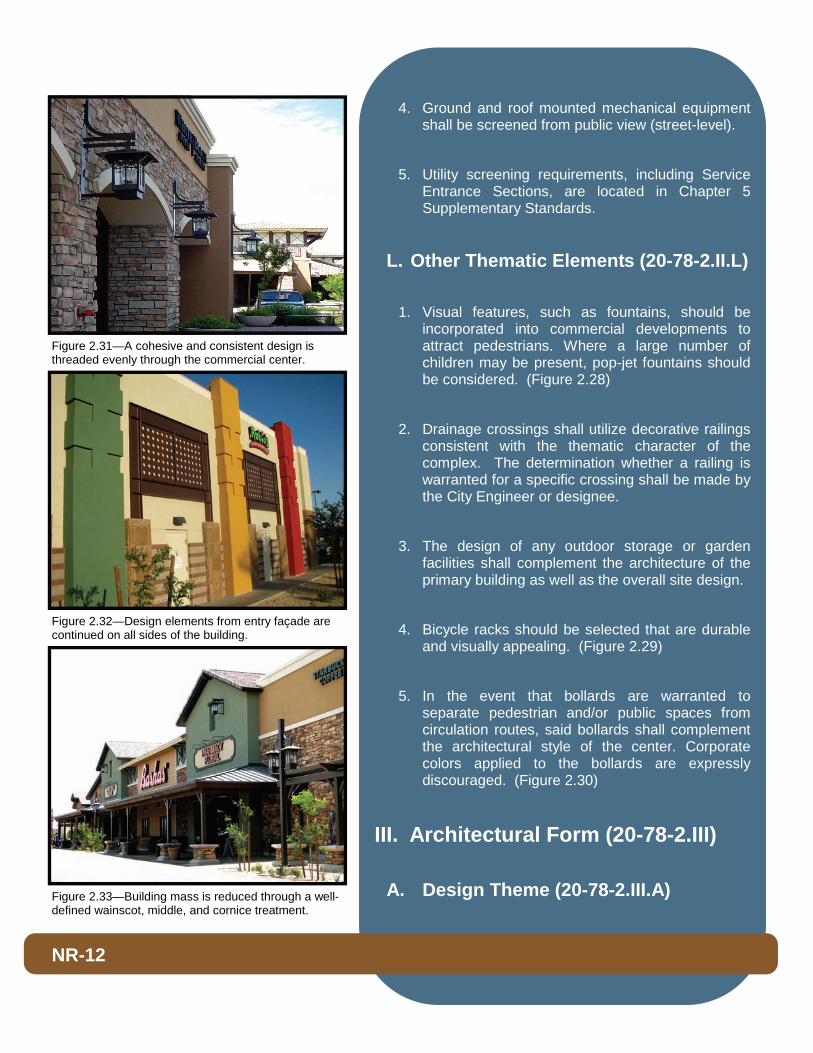
Figure 2.32—Design elements from entry façade are continued on all sides of the building.
Figure 2.31—A cohesive and consistent design is threaded evenly through the commercial center.
Figure 2.33—Building mass is reduced through a well-defined wainscot, middle, and cornice treatment.

1. In an effort to encourage diversity in design, corporate templates should be contextual and tempered with localized treatments and design alternatives.
2. Multi-tenant commercial centers shall have a consistent architectural and thematic palette throughout the development.
3. A commercial complex shall establish and maintain a consistent architectural style with individual buildings designed with complementary forms and materials. (Figure 2.31)
4. All sides of the buildings shall receive proportionate design consideration and treatment (360 degree architecture). (Figure 2.32)
B. Building Mass (20-78-2.III.B)
1. Perceived building mass shall be reduced by dividing the building mass into small scale components by providing a well-defined base, middle and top to the building. (Figures 2.33, 2.34)
a. A solid building base may be achieved by elements such as low planters and walls, base planting, a base architectural veneer banding (wainscot) and treatments defined by a different material, texture or color.
b. A distinct building middle may be achieved by the addition of covered walkways, trellises, colonnades, or architectural awnings that provide deep shadow.
c. A well defined building top may be achieved by utilizing features such as distinct and multiple architectural roof forms, clearly pronounced eaves, and distinct parapet designs and cornice treatments.
2. Building mass should be broken by dividing the building into smaller components and creating
NR-13
Figure 2.35— Building mass is reduced by creating a functional public gathering area between the buildings.
Figure 2.34—Perceived building scale is minimized by an architecturally distinct building middle and cornice.
Figure 2.36—Front façade utilizes varying window styles and sizes.
functional public space and pedestrian oriented areas between buildings. (Figure 2.35)
3. The use of colonnades along street fronting façades should be considered to reduce the massing of tall buildings and add pedestrian scale and interest.
4. Non-entry facades that face roads or views from public spaces should incorporate additional architectural treatments, such as pilasters, recessed areas, and windows with spandrel glass that give the appearance of windows facing the street.
5. Surface detailing, such as score lines or heavy stucco, should not serve as a substitute for distinctive massing.
C. Fenestration / Wall Penetrations (20-78-2.III.C)
1. Windows and doors should include visually prominent framing and accent elements. Materials, shape, and proportions shall complement the architectural style of the building.
2. Twenty-five percent (25%) of the primary entry façade shall be windows. Commercial developments in excess of 70,000 square feet shall provide fifteen percent (15%) of the primary entry façade in windows. Industrial developments shall provide ten percent (10%) of the entry façade in windows. Faux windows may be counted toward this requirement. (Figure 2.36)
3. Windows shall employ design details appropriate to the architecture, such as mullions, arched windows, shutters/faux shutters, window surrounds, awnings, and canopies to break the scale of the façade into smaller components. (Figure 2.37)
NR-14
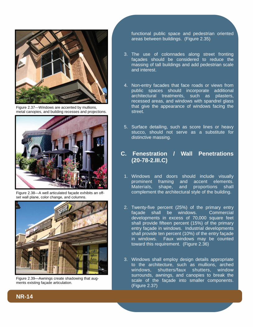
Figure 2.38—A well articulated façade exhibits an off-set wall plane, color change, and columns.
Figure 2.37—Windows are accented by mullions, metal canopies, and building recesses and projections.
Figure 2.39—Awnings create shadowing that aug-ments existing façade articulation.
D. Façade Articulation (20-78-2.III.D)
1. To ensure minimal amount of horizontal articulation/undulation, no building wall on the primary building façade shall run more than fifty (50) feet without employing one (1) or more of the following: (Figure 2.38)
a. A twelve (12) inch offset in wall plane;
b. A column or pier at least one (1) foot wide and eight (8) inches deep;
c. A building corner or projection;
d. Or significant texture change.
2. Architectural elements, such as overhangs, trellises, projections, awnings, insets, material, texture, and color, shall be used to create shadow patterns that contribute to the building’s character. (Figure 2.39)
3. Alternative designs will be reviewed for consistency with the intent of this section.
E. Roof Planes (20-78-2.III.E)
1. Rooflines shall be varied in height, form, and materials. Parapet rooflines shall be varied by stepping up and down or incorporating pitched roof elements. (Figure 2.40)
2. Parapet walls shall be designed and constructed in a manner to appear as a solid, three-dimensional form rather than a veneer. Parapets should include one (1) or more of the following detail treatments: (Figure 2.41)
a. Pre-cast elements;
b. Continuous banding or projecting cornices;
c. Dentils;
d. Caps;
NR-15
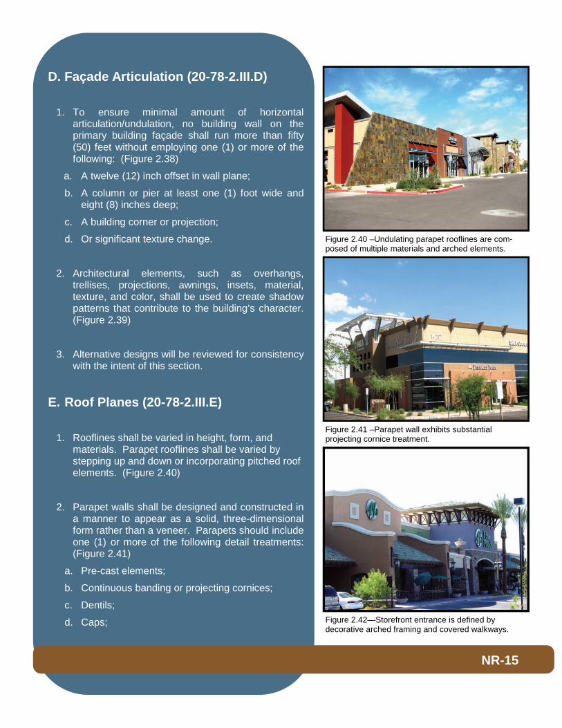
Figure 2.41 –Parapet wall exhibits substantial projecting cornice treatment.
Figure 2.40 –Undulating parapet rooflines are com-posed of multiple materials and arched elements.
Figure 2.42—Storefront entrance is defined by decorative arched framing and covered walkways.
e. Variety in pitch (sculpted);
f. Clean edges without unfinished flashing.
3. Deep overhangs should be integrated to create shadow and add depth to facades.
4. All roof-mounted mechanical equipment shall be screened from view. A line of sight exhibit shall be provided showing the effectiveness of the proposed screening methods from the public right- of-way. For projects abutting single-family residential homes, mechanical equipment shall be screened from all adjacent second s t o r y windows.
5. All screening materials shall be compatible with the colors, materials, and design of the building.
F. Storefront Proportion (20-78-2.III.F)
1. The main entry into a store should be emphasized to announce a point of arrival in one or more of the following ways: (Figure 2.42 and 2.43)
a. Flanked by columns, decorative fixtures, or other details;
b. Recessed within a larger arched or cased decorative opening;
c. Covered by means of a portico (formal porch) projecting from or set into the building face;
d. Punctuated by means of a change in roofline, tower, or a break in the surface of the subject wall.
2. Commercial storefront entries should be recessed and/or sheltered by a covered arcade structure, colonnade, canopy, or awning.
G. Colors and Materials (20-78-2.III.G)
NR-16
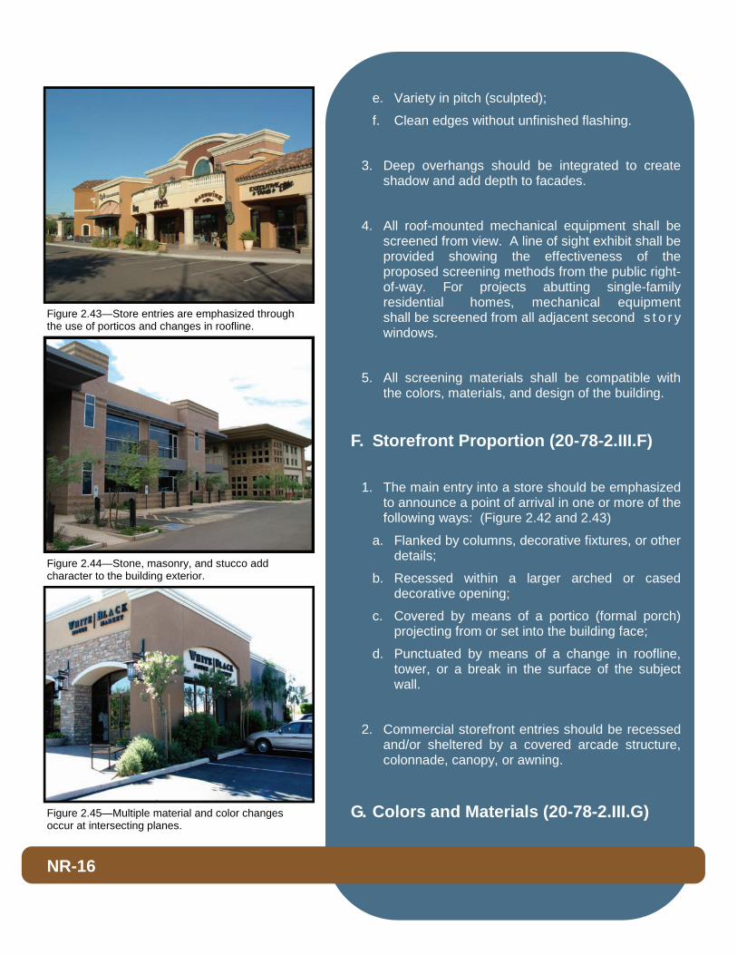
Figure 2.43—Store entries are emphasized through the use of porticos and changes in roofline.
Figure 2.44—Stone, masonry, and stucco add character to the building exterior.
Figure 2.45—Multiple material and color changes occur at intersecting planes.
1. All developments shall employ the integrative use of multiple exterior accent materials including, but not limited to, veneers, brick, stone, and masonry in appropriate quantities with the proposed elevations.
2. Material changes shall occur at intersecting planes, preferably at the inside corners of changing wall planes or where architectural elements intersect, such as pilaster, projection, or fence line. (Figure 2.44 and 2.45)
3. When stucco is utilized a light to smooth finish is required and shall be blended with other finish materials, such as stone, brick, wood, and/or iron.
4. Material and colors shall be used to enhance different parts of the building’s façade.
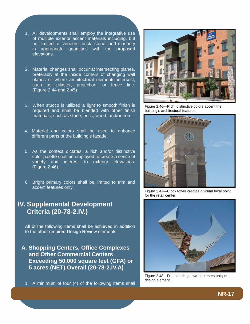
5. As the context dictates, a rich and/or distinctive color palette shall be employed to create a sense of variety and interest to exterior elevations. (Figure 2.46)
6. Bright primary colors shall be limited to trim and accent features only.
IV. Supplemental Development Criteria (20-78-2.IV.)
All of the following items shall be achieved in addition to the other required Design Review elements:
A. Shopping Centers, Office Complexes and Other Commercial Centers Exceeding 50,000 square feet (GFA) or 5 acres (NET) Overall (20-78-2.IV.A)
1. A minimum of four (4) of the following items shall
NR-17
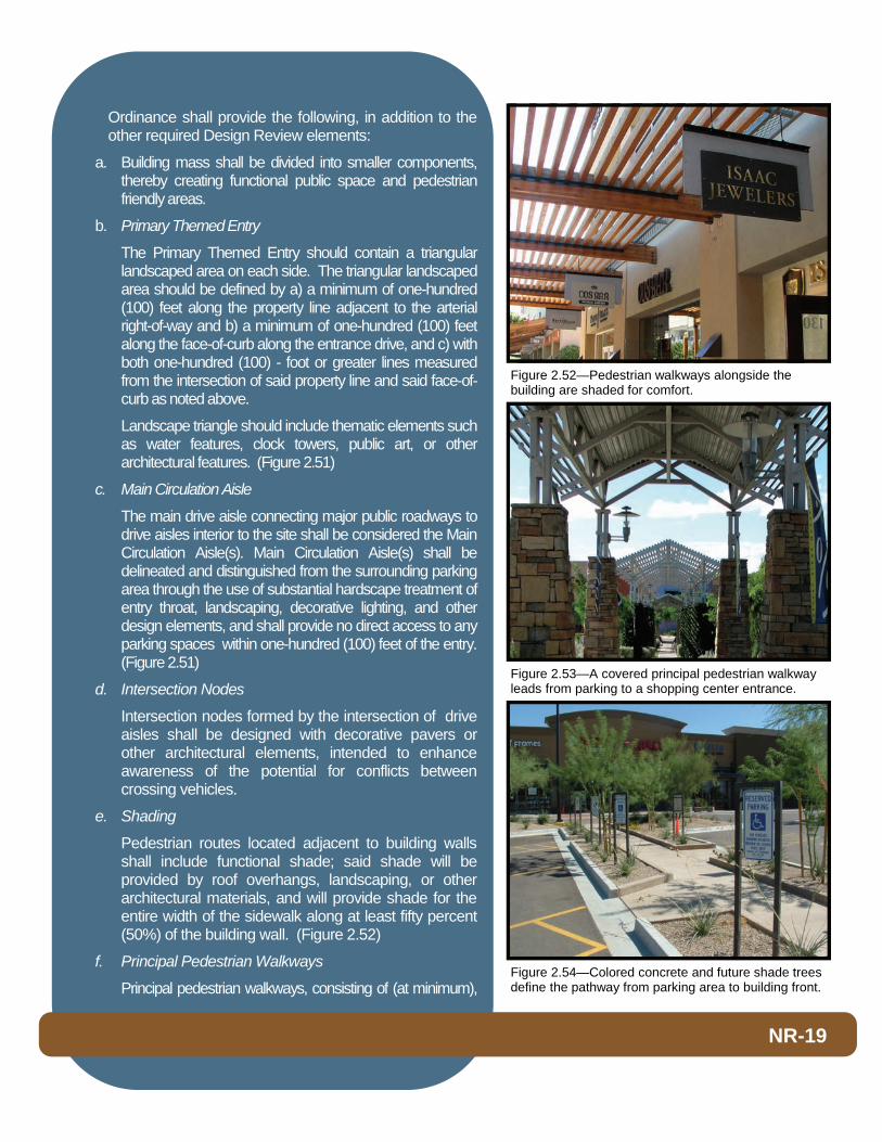
Figure 2.47—Clock tower creates a visual focal point for the retail center.
Figure 2.46—Rich, distinctive colors accent the building’s architectural features.
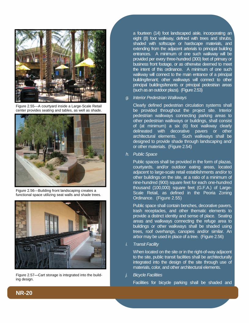
Figure 2.48—Freestanding artwork creates unique design element.

be achieved in addition to the other required Design Review elements:
a. Provide freestanding architectural features that are thematically consistent. Such features may include, but are not limited to, entry arches, fountains, formal entry aisles, obelisks, trellises, integrated artwork, clock towers, and other similar features. (Figure 2.47, 2.48, 2.49 & 2.50)
b. Provide angled or staggered building orientation to achieve varied alignment of building fronts and site design features that in turn create functional outdoor spaces and/or enhanced intersection feature.
c. Provide tree-lined “Boulevard” at median break(s), with detached sidewalks and landscaping.
d. Where appropriate, locate artistic elements in open public locations. Artistic elements must be consistent with the overall theme of the center/facility. Artistic elements may include sculptures and murals, gates, fences, walls, benches, fountains, walkways, etc. (Figure 2.49)
e. Stagger parking setback by at least five (5) feet or vary orientation of parking lot along arterial streetscape, while maintaining the minimum required setback from the right-of-way.
f. Incorporate planter and seating features in pedestrian areas throughout the site, including areas along the front of the buildings.
g. On-site landscaping exceeds 25% of the net site area.
h. One or more buildings are pushed to the street such that there is no intervening parking between the building and streetline.
i. Any other design amenity, which is otherwise not required but which meets the general intent for design innovation, may be substituted for any of the above additional quality standards.
B. Large Scale Retail (20-78-2.IV.B)
1. Any developments involving a Large-Scale Retail establishment as defined in the Peoria Zoning
NR-18
Figure 2.51—Triangular landscape areas are located at the entrance to a Primary Themed Entry.
Figure 2.50—Integrated freestanding iconography help establish center identity.
Figure 2.49—Artfully designed fountain creates respite for the community.
Ordinance shall provide the following, in addition to the other required Design Review elements:
a. Building mass shall be divided into smaller components, thereby creating functional public space and pedestrian friendly areas.
b. Primary Themed Entry
The Primary Themed Entry should contain a triangular landscaped area on each side. The triangular landscaped area should be defined by a) a minimum of one-hundred (100) feet along the property line adjacent to the arterial right-of-way and b) a minimum of one-hundred (100) feet along the face-of-curb along the entrance drive, and c) with both one-hundred (100) - foot or greater lines measured from the intersection of said property line and said face-of-curb as noted above.
Landscape triangle should include thematic elements such as water features, clock towers, public art, or other architectural features. (Figure 2.51)
c. Main Circulation Aisle
The main drive aisle connecting major public roadways to drive aisles interior to the site shall be considered the Main Circulation Aisle(s). Main Circulation Aisle(s) shall be delineated and distinguished from the surrounding parking area through the use of substantial hardscape treatment of entry throat, landscaping, decorative lighting, and other design elements, and shall provide no direct access to any parking spaces within one-hundred (100) feet of the entry. (Figure 2.51)
d. Intersection Nodes
Intersection nodes formed by the intersection of drive aisles shall be designed with decorative pavers or other architectural elements, intended to enhance awareness of the potential for conflicts between crossing vehicles.
e. Shading
Pedestrian routes located adjacent to building walls shall include functional shade; said shade will be provided by roof overhangs, landscaping, or other architectural materials, and will provide shade for the entire width of the sidewalk along at least fifty percent (50%) of the building wall. (Figure 2.52)
f. Principal Pedestrian Walkways
Principal pedestrian walkways, consisting of (at minimum),
NR-19
Figure 2.54—Colored concrete and future shade trees define the pathway from parking area to building front.
Figure 2.53—A covered principal pedestrian walkway leads from parking to a shopping center entrance.
Figure 2.52—Pedestrian walkways alongside the building are shaded for comfort.
a fourteen (14) foot landscaped aisle, incorporating an eight (8) foot walkway, defined with trees and shrubs, shaded with softscape or hardscape materials, and extending from the adjacent arterials to principal building entrances. A minimum of one such walkway will be provided per every three-hundred (300) feet of primary or business front footage, or as otherwise deemed to meet the intent of this ordinance. A minimum of one such walkway will connect to the main entrance of a principal building/tenant; other walkways will connect to other principal buildings/tenants or principal pedestrian areas (such as an outdoor plaza). (Figure 2.53)
g. Interior Pedestrian Walkways
Clearly defined pedestrian circulation systems shall be provided throughout the project site. Interior pedestrian walkways connecting parking areas to other pedestrian walkways or buildings, shall consist of (at minimum) a six (6) foot walkway clearly delineated with decorative pavers or other architectural elements. Such walkways shall be designed to provide shade through landscaping and/or other materials. (Figure 2.54)
h. Public Space
Public spaces shall be provided in the form of plazas, courtyards, and/or outdoor eating areas, located adjacent to large-scale retail establishments and/or to other buildings on the site, at a ratio of a minimum of nine-hundred (900) square feet for each one-hundred thousand (100,000) square feet (G.F.A.) of Large-Scale Retail, as defined in the Peoria Zoning Ordinance. (Figure 2.55)
Public space shall contain benches, decorative pavers, trash receptacles, and other thematic elements to provide a distinct identity and sense of place. Seating areas and walkways connecting the refuge area to buildings or other walkways shall be shaded using trees, roof overhangs, canopies and/or similar. An arbor may be used in place of a tree. (Figure 2.56)
i. Transit Facility
When located on the site or in the right-of-way adjacent to the site, public transit facilities shall be architecturally integrated into the design of the site through use of materials, color, and other architectural elements.
j. Bicycle Facilities
Facilities for bicycle parking shall be shaded and
NR-20
Figure 2.57—Cart storage is integrated into the build-ing design.
Figure 2.56—Building front landscaping creates a functional space utilizing seat walls and shade trees.
Figure 2.55—A courtyard inside a Large-Scale Retail center provides seating and tables, as well as shade.

integrated into the site at the main entrance of the principal building.
k. Cart Storage
The design of shopping cart storage facilities shall complement the established architectural theme of center. (Figure 2.57)
C. Industrial (20-78-2.IV.C)
1. Wall forms shall be articulated with changes in massing, colors, and material. Such a change in horizontal walls shall occur every fifty (50) feet or less. (Figures 2.58 and 2.59)
2. Where appropriate, colonnades should be utilized along the street frontage façade to reduce the massing of tall buildings and add pedestrian scale.
3. Structures two-stories or higher should incorporate a step in the vertical plane to reduce the scale of the building. This step can be accomplished by stepping back the floors above the first or by projecting first floor elements or wall surfaces.
4. A full pitched roof over an entire industrial building is not realistic. However, where feasible and appropriate to the architectural style for the building, a pitched roof element should be provided over the entry and/or office portion of the structure. (Figure 2.60)
5. Pre-cast walls/tilt-up shall incorporate reveals, recessed panels, recessed windows, and/or molding to articulate the building exterior. (Figure 2.61)
6. All concrete pre-cast/tilt-up buildings shall be designed to have an exterior appearance of conventional built structures utilizing surface treatments such as stucco, plaster, glass, stone, brick, or decorative masonry.
NR-21
Figure 2.58—Curved wall and tile pattern interrupt the horizontal wall plane to create visual interest.
Figure 2.60—Multi-planar components introduce depth and direction.
Figure 2.59—Prominent entry is defined by variation in materials.
7. Expansive paved areas located between the street and the building should be avoided in favor of multiple small lots separated by landscaping and buildings.
8. To soften the transition between industrial and residential uses, elevations facing residential uses shall be substantially consistent with the architecture exhibited on the front elevation.
D. Gasoline Stations & Car Washes (20-78-2.IV.D)
1. All structures on-site (including canopies, kiosks, car wash facilities, gas pump columns, bollards protecting the gas pumps, gas pumps (excluding sign toppers), etc.) shall be consistent with and complement the architectural design of the primary building and overall project site. (Figure 2.62)
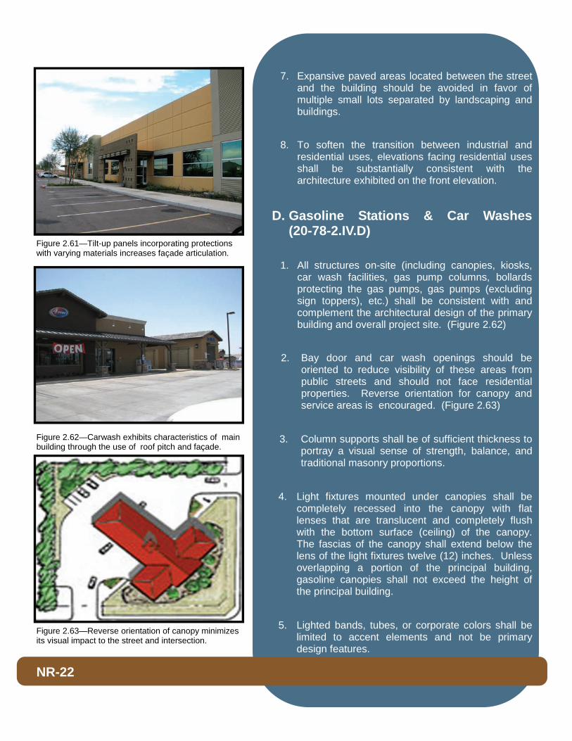
2. Bay door and car wash openings should be oriented to reduce visibility of these areas from public streets and should not face residential properties. Reverse orientation for canopy and service areas is encouraged. (Figure 2.63)
3. Column supports shall be of sufficient thickness to portray a visual sense of strength, balance, and traditional masonry proportions.
4. Light fixtures mounted under canopies shall be completely recessed into the canopy with flat lenses that are translucent and completely flush with the bottom surface (ceiling) of the canopy. The fascias of the canopy shall extend below the lens of the light fixtures twelve (12) inches. Unless overlapping a portion of the principal building, gasoline canopies shall not exceed the height of the principal building.
5. Lighted bands, tubes, or corporate colors shall be limited to accent elements and not be primary design features.
NR-22
Figure 2.63—Reverse orientation of canopy minimizes its visual impact to the street and intersection.
Figure 2.62—Carwash exhibits characteristics of main building through the use of roof pitch and façade.
Figure 2.61—Tilt-up panels incorporating protections with varying materials increases façade articulation.
6. All gas tank vent piping shall be screened from arterial streets and public view.
7. Car wash facilities should incorporate small plazas or other areas for patrons to comfortably wait while their vehicles are being washed.
E. Drive-Through / Drive-Up Facilities (20-78-2.IV.E)
1. The primary visual presence along major street frontage should be the building front, not the drive-through aisle or parking lots.
2. Drive-through menu boards shall be screened from street view, and architecturally integrated with building design through the use of common materials and colors.
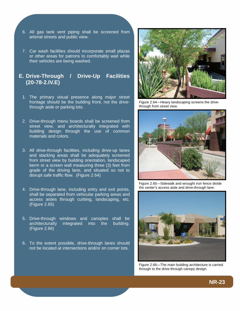
3. All drive-through facilities, including drive-up lanes and stacking areas shall be adequately screened from street view by building orientation, landscaped berm or a screen wall measuring three (3) feet from grade of the driving lane, and situated so not to disrupt safe traffic flow. (Figure 2.64)
4. Drive-through lane, including entry and exit points, shall be separated from vehicular parking areas and access aisles through curbing, landscaping, etc. (Figure 2.65)
5. Drive-through windows and canopies shall be architecturally integrated into the building. (Figure 2.66)
6. To the extent possible, drive-through lanes should not be located at intersections and/or on corner lots.
NR-23
Figure 2.66—The main building architecture is carried through to the drive-through canopy design.
Figure 2.65—Sidewalk and wrought iron fence divide the center’s access aisle and drive-through lane.
Figure 2.64—Heavy landscaping screens the drive-through from street view.