Embed Size (px)
Citation preview
A Practical Guide to Free-Energy Devices Author: Patrick J. Kelly
Chapter 2: Moving Pulsed Systems
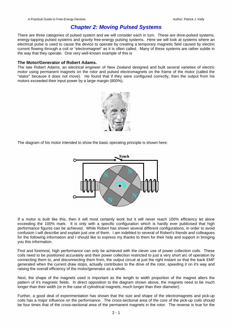
There are three categories of pulsed system and we will consider each in turn. These are drive-pulsed systems, energy-tapping pulsed systems and gravity free-energy pulsing systems. Here we will look at systems where an electrical pulse is used to cause the device to operate by creating a temporary magnetic field caused by electric current flowing through a coil or “electromagnet” as it is often called. Many of these systems are rather subtle in the way that they operate. One very well-known example of this is The Motor/Generator of Robert Adams. The late Robert Adams, an electrical engineer of New Zealand designed and built several varieties of electric motor using permanent magnets on the rotor and pulsed electromagnets on the frame of the motor (called the "stator" because it does not move). He found that if they were configured correctly, then the output from his motors exceeded their input power by a large margin (800%).
The diagram of his motor intended to show the basic operating principle is shown here:
If a motor is built like this, then it will most certainly work but it will never reach 100% efficiency let alone exceeding the 100% mark. It is only with a specific configuration which is hardly ever publicised that high performance figures can be achieved. While Robert has shown several different configurations, in order to avoid confusion I will describe and explain just one of them. I am indebted to several of Robert's friends and colleagues for the following information and I should like to express my thanks to them for their help and support in bringing you this information. First and foremost, high performance can only be achieved with the clever use of power collection coils. These coils need to be positioned accurately and their power collection restricted to just a very short arc of operation by connecting them to, and disconnecting them from, the output circuit at just the right instant so that the back EMF generated when the current draw stops, actually contributes to the drive of the rotor, speeding it on it's way and raising the overall efficiency of the motor/generator as a whole. Next, the shape of the magnets used is important as the length to width proportion of the magnet alters the pattern of it's magnetic fields. In direct opposition to the diagram shown above, the magnets need to be much longer than their width (or in the case of cylindrical magnets, much longer than their diameter). Further, a good deal of experimentation has shown that the size and shape of the electromagnets and pick-up coils has a major influence on the performance. The cross-sectional area of the core of the pick-up coils should be four times that of the cross-sectional area of the permanent magnets in the rotor. The reverse is true for the
2 - 1
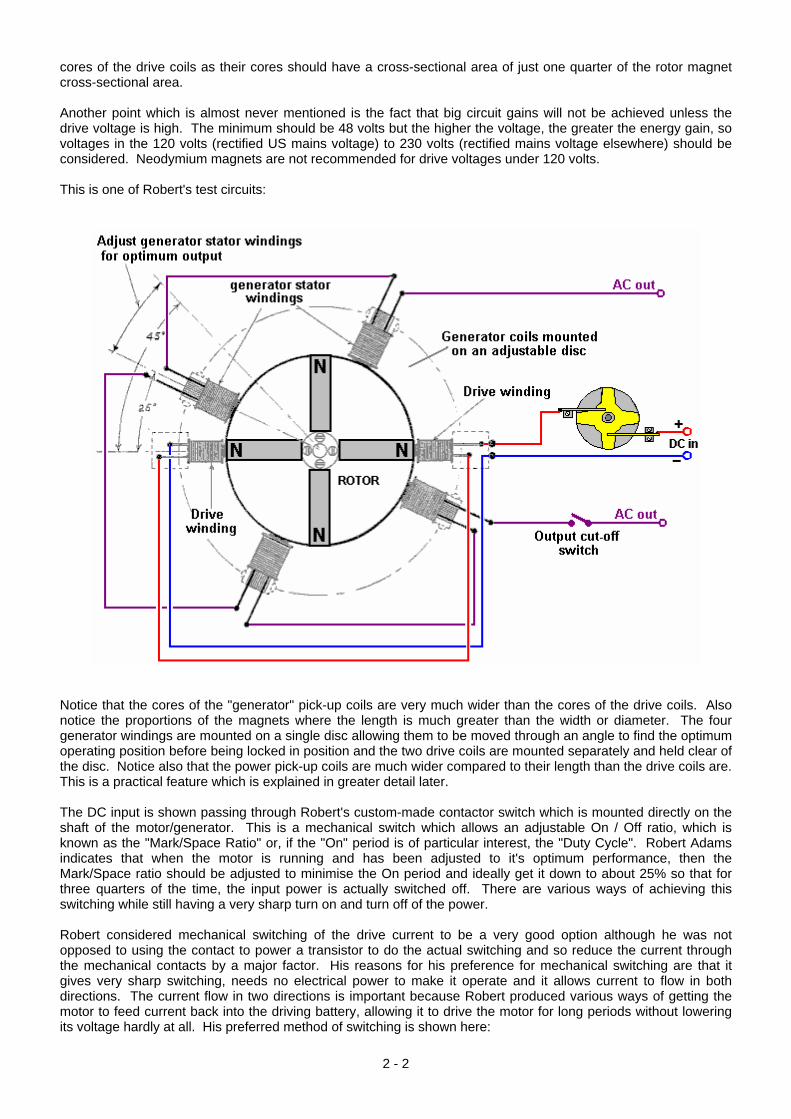
cores of the drive coils as their cores should have a cross-sectional area of just one quarter of the rotor magnet cross-sectional area. Another point which is almost never mentioned is the fact that big circuit gains will not be achieved unless the drive voltage is high. The minimum should be 48 volts but the higher the voltage, the greater the energy gain, so voltages in the 120 volts (rectified US mains voltage) to 230 volts (rectified mains voltage elsewhere) should be considered. Neodymium magnets are not recommended for drive voltages under 120 volts. This is one of Robert's test circuits:
Notice that the cores of the "generator" pick-up coils are very much wider than the cores of the drive coils. Also notice the proportions of the magnets where the length is much greater than the width or diameter. The four generator windings are mounted on a single disc allowing them to be moved through an angle to find the optimum operating position before being locked in position and the two drive coils are mounted separately and held clear of the disc. Notice also that the power pick-up coils are much wider compared to their length than the drive coils are. This is a practical feature which is explained in greater detail later. The DC input is shown passing through Robert's custom-made contactor switch which is mounted directly on the shaft of the motor/generator. This is a mechanical switch which allows an adjustable On / Off ratio, which is known as the "Mark/Space Ratio" or, if the "On" period is of particular interest, the "Duty Cycle". Robert Adams indicates that when the motor is running and has been adjusted to it's optimum performance, then the Mark/Space ratio should be adjusted to minimise the On period and ideally get it down to about 25% so that for three quarters of the time, the input power is actually switched off. There are various ways of achieving this switching while still having a very sharp turn on and turn off of the power. Robert considered mechanical switching of the drive current to be a very good option although he was not opposed to using the contact to power a transistor to do the actual switching and so reduce the current through the mechanical contacts by a major factor. His reasons for his preference for mechanical switching are that it gives very sharp switching, needs no electrical power to make it operate and it allows current to flow in both directions. The current flow in two directions is important because Robert produced various ways of getting the motor to feed current back into the driving battery, allowing it to drive the motor for long periods without lowering its voltage hardly at all. His preferred method of switching is shown here:
2 - 2
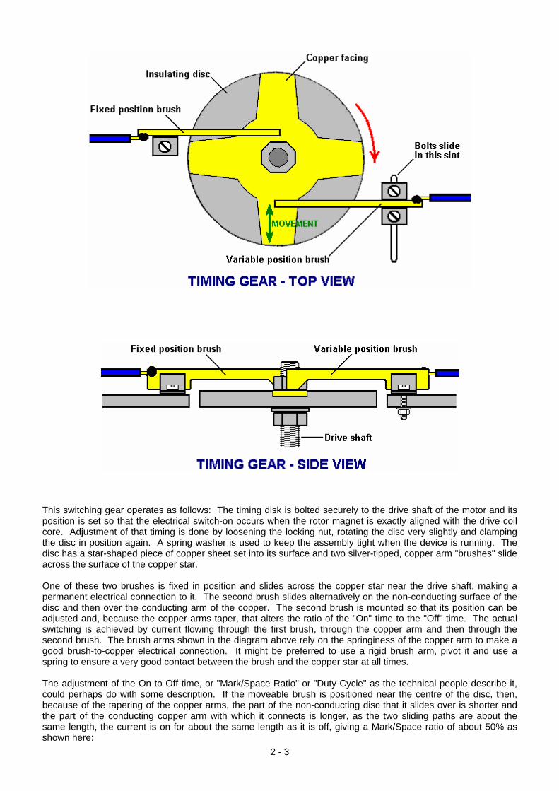
This switching gear operates as follows: The timing disk is bolted securely to the drive shaft of the motor and its position is set so that the electrical switch-on occurs when the rotor magnet is exactly aligned with the drive coil core. Adjustment of that timing is done by loosening the locking nut, rotating the disc very slightly and clamping the disc in position again. A spring washer is used to keep the assembly tight when the device is running. The disc has a star-shaped piece of copper sheet set into its surface and two silver-tipped, copper arm "brushes" slide across the surface of the copper star. One of these two brushes is fixed in position and slides across the copper star near the drive shaft, making a permanent electrical connection to it. The second brush slides alternatively on the non-conducting surface of the disc and then over the conducting arm of the copper. The second brush is mounted so that its position can be adjusted and, because the copper arms taper, that alters the ratio of the "On" time to the "Off" time. The actual switching is achieved by current flowing through the first brush, through the copper arm and then through the second brush. The brush arms shown in the diagram above rely on the springiness of the copper arm to make a good brush-to-copper electrical connection. It might be preferred to use a rigid brush arm, pivot it and use a spring to ensure a very good contact between the brush and the copper star at all times. The adjustment of the On to Off time, or "Mark/Space Ratio" or "Duty Cycle" as the technical people describe it, could perhaps do with some description. If the moveable brush is positioned near the centre of the disc, then, because of the tapering of the copper arms, the part of the non-conducting disc that it slides over is shorter and the part of the conducting copper arm with which it connects is longer, as the two sliding paths are about the same length, the current is on for about the same length as it is off, giving a Mark/Space ratio of about 50% as shown here:
2 - 3
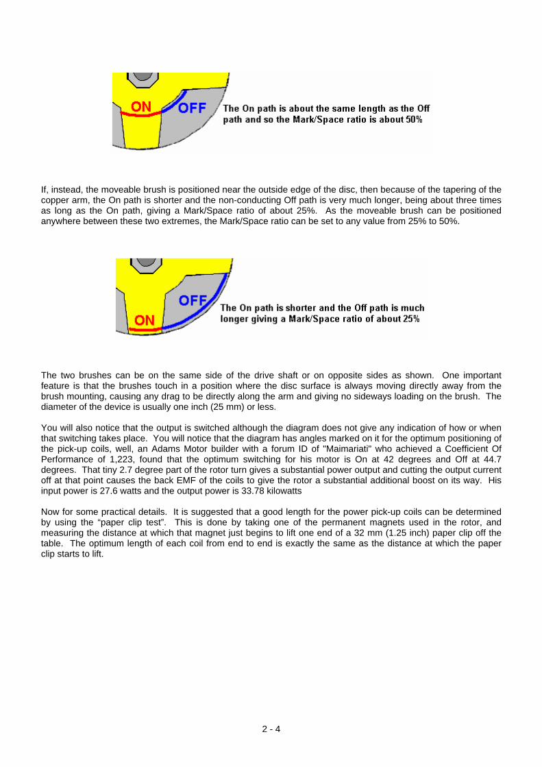
If, instead, the moveable brush is positioned near the outside edge of the disc, then because of the tapering of the copper arm, the On path is shorter and the non-conducting Off path is very much longer, being about three times as long as the On path, giving a Mark/Space ratio of about 25%. As the moveable brush can be positioned anywhere between these two extremes, the Mark/Space ratio can be set to any value from 25% to 50%.
The two brushes can be on the same side of the drive shaft or on opposite sides as shown. One important feature is that the brushes touch in a position where the disc surface is always moving directly away from the brush mounting, causing any drag to be directly along the arm and giving no sideways loading on the brush. The diameter of the device is usually one inch (25 mm) or less. You will also notice that the output is switched although the diagram does not give any indication of how or when that switching takes place. You will notice that the diagram has angles marked on it for the optimum positioning of the pick-up coils, well, an Adams Motor builder with a forum ID of "Maimariati" who achieved a Coefficient Of Performance of 1,223, found that the optimum switching for his motor is On at 42 degrees and Off at 44.7 degrees. That tiny 2.7 degree part of the rotor turn gives a substantial power output and cutting the output current off at that point causes the back EMF of the coils to give the rotor a substantial additional boost on its way. His input power is 27.6 watts and the output power is 33.78 kilowatts Now for some practical details. It is suggested that a good length for the power pick-up coils can be determined by using the “paper clip test”. This is done by taking one of the permanent magnets used in the rotor, and measuring the distance at which that magnet just begins to lift one end of a 32 mm (1.25 inch) paper clip off the table. The optimum length of each coil from end to end is exactly the same as the distance at which the paper clip starts to lift.
2 - 4
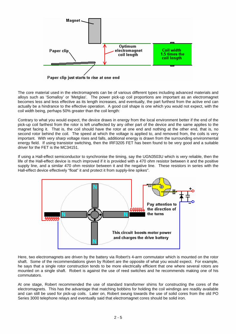
The core material used in the electromagnets can be of various different types including advanced materials and alloys such as ‘Somalloy’ or 'Metglas'. The power pick-up coil proportions are important as an electromagnet becomes less and less effective as its length increases, and eventually, the part furthest from the active end can actually be a hindrance to the effective operation. A good coil shape is one which you would not expect, with the coil width being, perhaps 50% greater than the coil length: Contrary to what you would expect, the device draws in energy from the local environment better if the end of the pick-up coil farthest from the rotor is left unaffected by any other part of the device and the same applies to the magnet facing it. That is, the coil should have the rotor at one end and nothing at the other end, that is, no second rotor behind the coil. The speed at which the voltage is applied to, and removed from, the coils is very important. With very sharp voltage rises and falls, additional energy is drawn from the surrounding environmental energy field. If using transistor switching, then the IRF3205 FET has been found to be very good and a suitable driver for the FET is the MC34151. If using a Hall-effect semiconductor to synchronise the timing, say the UGN3503U which is very reliable, then the life of the Hall-effect device is much improved if it is provided with a 470 ohm resistor between it and the positive supply line, and a similar 470 ohm resistor between it and the negative line. These resistors in series with the Hall-effect device effectively “float” it and protect it from supply-line spikes".
Here, two electromagnets are driven by the battery via Robert's 4-arm commutator which is mounted on the rotor shaft. Some of the recommendations given by Robert are the opposite of what you would expect. For example, he says that a single rotor construction tends to be more electrically efficient that one where several rotors are mounted on a single shaft. Robert is against the use of reed switches and he recommends making one of his commutators. At one stage, Robert recommended the use of standard transformer shims for constructing the cores of the electromagnets. This has the advantage that matching bobbins for holding the coil windings are readily available and can still be used for pick-up coils. Later on, Robert swung towards the use of solid cores from the old PO Series 3000 telephone relays and eventually said that electromagnet cores should be solid iron.
2 - 5
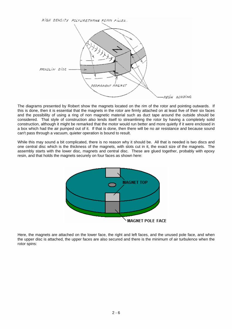
The diagrams presented by Robert show the magnets located on the rim of the rotor and pointing outwards. If this is done, then it is essential that the magnets in the rotor are firmly attached on at least five of their six faces and the possibility of using a ring of non magnetic material such as duct tape around the outside should be considered. That style of construction also lends itself to streamlining the rotor by having a completely solid construction, although it might be remarked that the motor would run better and more quietly if it were enclosed in a box which had the air pumped out of it. If that is done, then there will be no air resistance and because sound can't pass through a vacuum, quieter operation is bound to result. While this may sound a bit complicated, there is no reason why it should be. All that is needed is two discs and one central disc which is the thickness of the magnets, with slots cut in it, the exact size of the magnets. The assembly starts with the lower disc, magnets and central disc. These are glued together, probably with epoxy resin, and that holds the magnets securely on four faces as shown here:
Here, the magnets are attached on the lower face, the right and left faces, and the unused pole face, and when the upper disc is attached, the upper faces are also secured and there is the minimum of air turbulence when the rotor spins:
2 - 6
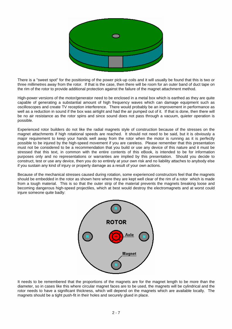
There is a "sweet spot" for the positioning of the power pick-up coils and it will usually be found that this is two or three millimetres away from the rotor. If that is the case, then there will be room for an outer band of duct tape on the rim of the rotor to provide additional protection against the failure of the magnet attachment method. High-power versions of the motor/generator need to be enclosed in a metal box which is earthed as they are quite capable of generating a substantial amount of high frequency waves which can damage equipment such as oscilloscopes and create TV reception interference. There would probably be an improvement in performance as well as a reduction in sound if the box was airtight and had the air pumped out of it. If that is done, then there will be no air resistance as the rotor spins and since sound does not pass through a vacuum, quieter operation is possible. Experienced rotor builders do not like the radial magnets style of construction because of the stresses on the magnet attachments if high rotational speeds are reached. It should not need to be said, but it is obviously a major requirement to keep your hands well away from the rotor when the motor is running as it is perfectly possible to be injured by the high-speed movement if you are careless. Please remember that this presentation must not be considered to be a recommendation that you build or use any device of this nature and it must be stressed that this text, in common with the entire contents of this eBook, is intended to be for information purposes only and no representations or warranties are implied by this presentation. Should you decide to construct, test or use any device, then you do so entirely at your own risk and no liability attaches to anybody else if you sustain any kind of injury or property damage as a result of your own actions. Because of the mechanical stresses caused during rotation, some experienced constructors feel that the magnets should be embedded in the rotor as shown here where they are kept well clear of the rim of a rotor which is made from a tough material. This is so that the outer strip of the material prevents the magnets breaking loose and becoming dangerous high-speed projectiles, which at best would destroy the electromagnets and at worst could injure someone quite badly:
It needs to be remembered that the proportions of the magnets are for the magnet length to be more than the diameter, so in cases like this where circular magnet faces are to be used, the magnets will be cylindrical and the rotor needs to have a significant thickness, which will depend on the magnets which are available locally. The magnets should be a tight push-fit in their holes and securely glued in place.
2 - 7
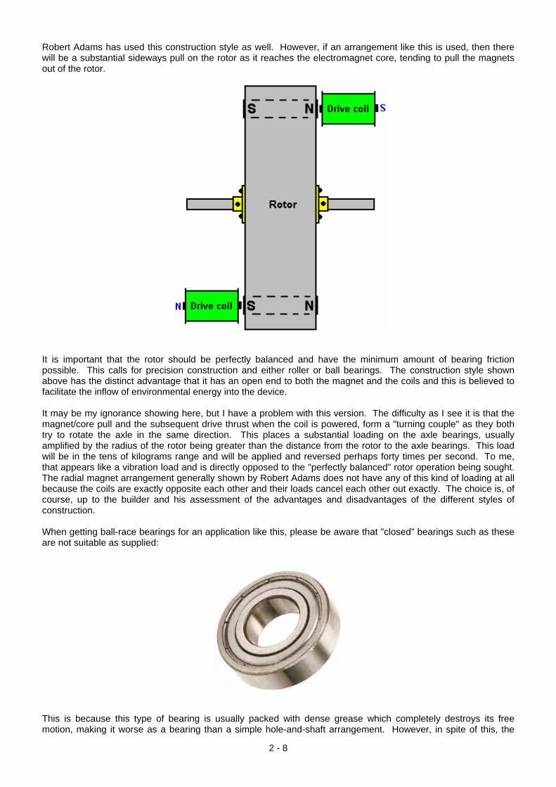
Robert Adams has used this construction style as well. However, if an arrangement like this is used, then there will be a substantial sideways pull on the rotor as it reaches the electromagnet core, tending to pull the magnets out of the rotor.
It is important that the rotor should be perfectly balanced and have the minimum amount of bearing friction possible. This calls for precision construction and either roller or ball bearings. The construction style shown above has the distinct advantage that it has an open end to both the magnet and the coils and this is believed to facilitate the inflow of environmental energy into the device. It may be my ignorance showing here, but I have a problem with this version. The difficulty as I see it is that the magnet/core pull and the subsequent drive thrust when the coil is powered, form a "turning couple" as they both try to rotate the axle in the same direction. This places a substantial loading on the axle bearings, usually amplified by the radius of the rotor being greater than the distance from the rotor to the axle bearings. This load will be in the tens of kilograms range and will be applied and reversed perhaps forty times per second. To me, that appears like a vibration load and is directly opposed to the "perfectly balanced" rotor operation being sought. The radial magnet arrangement generally shown by Robert Adams does not have any of this kind of loading at all because the coils are exactly opposite each other and their loads cancel each other out exactly. The choice is, of course, up to the builder and his assessment of the advantages and disadvantages of the different styles of construction. When getting ball-race bearings for an application like this, please be aware that "closed" bearings such as these are not suitable as supplied:
This is because this type of bearing is usually packed with dense grease which completely destroys its free motion, making it worse as a bearing than a simple hole-and-shaft arrangement. However, in spite of this, the
2 - 8
closed or "sealed" bearing is popular as the magnets tend to attract dirt and dust and if the device is not enclosed in a steel box as is necessary for the high power versions, then having the seal is considered to be an advantage. The way to deal with the grease packing is to soak the bearing in an isopropyal solvent cleaner to remove the manufacturer's grease, and then, when it has dried out, lubricate the bearing with two drops of a high quality thin oil. If it is intended to house the motor/generator in an earthed, sealed steel box then an alternative type of bearing which might be suitable is an open design like this:
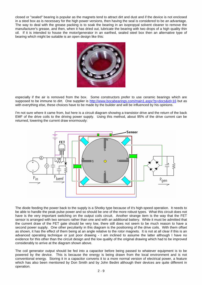
especially if the air is removed from the box. Some constructors prefer to use ceramic bearings which are supposed to be immune to dirt. One supplier is http://www.bocabearings.com/main1.aspx?p=docs&id=16 but as with everything else, these choices have to be made by the builder and will be influenced by his opinions. I'm not sure where it came from, but here is a circuit diagram showing a transistor drive and the return of the back EMF of the drive coils to the driving power supply. Using this method, about 95% of the drive current can be returned, lowering the current draw enormously:
The diode feeding the power back to the supply is a Shotky type because of it's high-speed operation. It needs to be able to handle the peak pulse power and so should be one of the more robust types. What this circuit does not have is the very important switching on the output coils circuit. Another strange item is the way that the FET sensor is arranged with two sensors rather than one and with an additional battery. While it must be admitted that the current draw of the FET gate should be very low, there still does not seem to be much reason to have a second power supply. One other peculiarity in this diagram is the positioning of the drive coils. With them offset as shown, it has the effect of them being at an angle relative to the rotor magnets. It is not at all clear if this is an advanced operating technique or just poor drawing - I am inclined to assume the latter although I have no evidence for this other than the circuit design and the low quality of the original drawing which had to be improved considerably to arrive at the diagram shown above.
2 - 9
The coil generator output should be fed into a capacitor before being passed to whatever equipment is to be powered by the device. This is because the energy is being drawn from the local environment and is not conventional energy. Storing it in a capacitor converts it to a more normal version of electrical power, a feature which has also been mentioned by Don Smith and by John Bedini although their devices are quite different in operation.
2 - 10
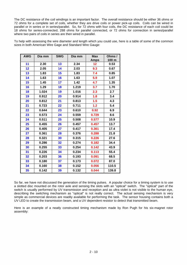
The DC resistance of the coil windings is an important factor. The overall resistance should be either 36 ohms or 72 ohms for a complete set of coils, whether they are drive coils or power pick-up coils. Coils can be wired in parallel or in series or in series/parallel. So, for 72 ohms with four coils, the DC resistance of each coil could be 18 ohms for series-connected, 288 ohms for parallel connected, or 72 ohms for connection in series/parallel where two pairs of coils in series are then wired in parallel. To help with assessing the wire diameter and length which you could use, here is a table of some of the common sizes in both American Wire Gage and Standard Wire Gauge:
AWG Dia mm SWG Dia mm Max Amps
Ohms / 100 m
11 2.30 13 2.34 12 0.53 12 2.05 14 2.03 9.3 0.67 13 1.83 15 1.83 7.4 0.85 14 1.63 16 1.63 5.9 1.07 15 1.45 17 1.42 4.7 1.35 16 1.29 18 1.219 3.7 1.70 18 1.024 19 1.016 2.3 2.7 19 0.912 20 0.914 1.8 3.4 20 0.812 21 0.813 1.5 4.3 21 0.723 22 0.711 1.2 5.4 22 0.644 23 0.610 0.92 6.9 23 0.573 24 0.559 0.729 8.6 24 0.511 25 0.508 0.577 10.9 25 0.455 26 0.457 0.457 13.7 26 0.405 27 0.417 0.361 17.4 27 0.361 28 0.376 0.288 21.8 28 0.321 30 0.315 0.226 27.6 29 0.286 32 0.274 0.182 34.4 30 0.255 33 0.254 0.142 43.9 31 0.226 34 0.234 0.113 55.4 32 0.203 36 0.193 0.091 68.5 33 0.180 37 0.173 0.072 87.0 34 0.160 38 0.152 0.056 110.5 35 0.142 39 0.132 0.044 139.8
So far, we have not discussed the generation of the timing pulses. A popular choice for a timing system is to use a slotted disc mounted on the rotor axle and sensing the slots with an "optical" switch. The "optical" part of the switch is usually performed by UV transmission and reception and as ultra violet is not visible to the human eye, describing the switching mechanism as "optical" is not really correct. The actual sensing mechanism is very simple as commercial devices are readily available for performing the task. The sensor housing contains both a UV LED to create the transmission beam, and a UV dependent resistor to detect that transmitted beam. Here is an example of a neatly constructed timing mechanism made by Ron Pugh for his six-magnet rotor assembly:
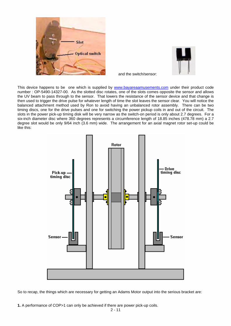
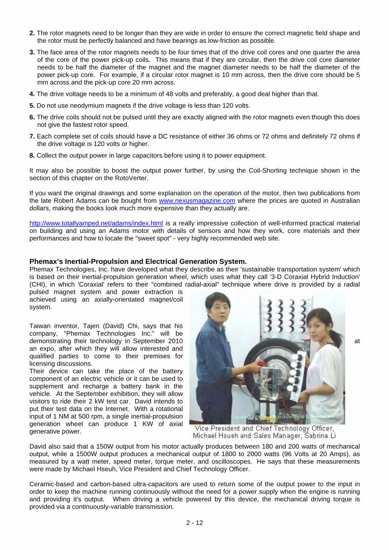
and the switch/sensor: This device happens to be one which is supplied by www.bayareaamusements.com under their product code number : OP-5490-14327-00. As the slotted disc rotates, one of the slots comes opposite the sensor and allows the UV beam to pass through to the sensor. That lowers the resistance of the sensor device and that change is then used to trigger the drive pulse for whatever length of time the slot leaves the sensor clear. You will notice the balanced attachment method used by Ron to avoid having an unbalanced rotor assembly. There can be two timing discs, one for the drive pulses and one for switching the power pickup coils in and out of the circuit. The slots in the power pick-up timing disk will be very narrow as the switch-on period is only about 2.7 degrees. For a six-inch diameter disc where 360 degrees represents a circumference length of 18.85 inches (478.78 mm) a 2.7 degree slot would be only 9/64 inch (3.6 mm) wide. The arrangement for an axial magnet rotor set-up could be like this:
So to recap, the things which are necessary for getting an Adams Motor output into the serious bracket are:
2 - 11 1. A performance of COP>1 can only be achieved if there are power pick-up coils.
2. The rotor magnets need to be longer than they are wide in order to ensure the correct magnetic field shape and the rotor must be perfectly balanced and have bearings as low-friction as possible.
3. The face area of the rotor magnets needs to be four times that of the drive coil cores and one quarter the area of the core of the power pick-up coils. This means that if they are circular, then the drive coil core diameter needs to be half the diameter of the magnet and the magnet diameter needs to be half the diameter of the power pick-up core. For example, if a circular rotor magnet is 10 mm across, then the drive core should be 5 mm across and the pick-up core 20 mm across.
4. The drive voltage needs to be a minimum of 48 volts and preferably, a good deal higher than that.
5. Do not use neodymium magnets if the drive voltage is less than 120 volts.
6. The drive coils should not be pulsed until they are exactly aligned with the rotor magnets even though this does not give the fastest rotor speed.
7. Each complete set of coils should have a DC resistance of either 36 ohms or 72 ohms and definitely 72 ohms if the drive voltage is 120 volts or higher.
8. Collect the output power in large capacitors before using it to power equipment. It may also be possible to boost the output power further, by using the Coil-Shorting technique shown in the section of this chapter on the RotoVerter. If you want the original drawings and some explanation on the operation of the motor, then two publications from the late Robert Adams can be bought from www.nexusmagazine.com where the prices are quoted in Australian dollars, making the books look much more expensive than they actually are. http://www.totallyamped.net/adams/index.html is a really impressive collection of well-informed practical material on building and using an Adams motor with details of sensors and how they work, core materials and their performances and how to locate the "sweet spot" - very highly recommended web site. Phemax’s Inertial-Propulsion and Electrical Generation System. Phemax Technologies, Inc. have developed what they describe as their 'sustainable transportation system' which is based on their inertial-propulsion generation wheel, which uses what they call '3-D Coraxial Hybrid Induction' (CHI), in which 'Coraxial' refers to their "combined radial-axial" technique where drive is provided by a radial pulsed magnet system and power extraction is achieved using an axially-orientated magnet/coil system.
Taiwan inventor, Tajen (David) Chi, says that his company, "Phemax Technologies Inc." will be demonstrating their technology in September 2010 at an expo, after which they will allow interested and qualified parties to come to their premises for licensing discussions. Their device can take the place of the battery component of an electric vehicle or it can be used to supplement and recharge a battery bank in the vehicle. At the September exhibition, they will allow visitors to ride their 2 kW test car. David intends to put their test data on the Internet. With a rotational input of 1 NM at 500 rpm, a single inertial-propulsion generation wheel can produce 1 KW of axial generative power. David also said that a 150W output from his motor actually produces between 180 and 200 watts of mechanical output, while a 1500W output produces a mechanical output of 1800 to 2000 watts (96 Volts at 20 Amps), as measured by a watt meter, speed meter, torque meter, and oscilloscopes. He says that these measurements were made by Michael Hseuh, Vice President and Chief Technology Officer. Ceramic-based and carbon-based ultra-capacitors are used to return some of the output power to the input in order to keep the machine running continuously without the need for a power supply when the engine is running and providing it's output. When driving a vehicle powered by this device, the mechanical driving torque is provided via a continuously-variable transmission.
2 - 12
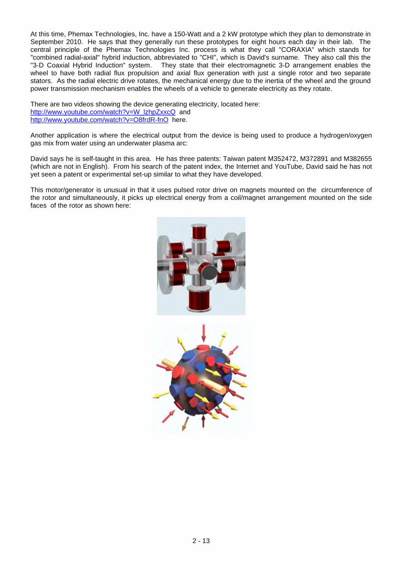
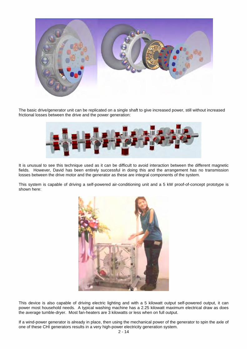
At this time, Phemax Technologies, Inc. have a 150-Watt and a 2 kW prototype which they plan to demonstrate in September 2010. He says that they generally run these prototypes for eight hours each day in their lab. The central principle of the Phemax Technologies Inc. process is what they call "CORAXIA" which stands for "combined radial-axial" hybrid induction, abbreviated to "CHI", which is David's surname. They also call this the "3-D Coaxial Hybrid Induction" system. They state that their electromagnetic 3-D arrangement enables the wheel to have both radial flux propulsion and axial flux generation with just a single rotor and two separate stators. As the radial electric drive rotates, the mechanical energy due to the inertia of the wheel and the ground power transmission mechanism enables the wheels of a vehicle to generate electricity as they rotate. There are two videos showing the device generating electricity, located here: http://www.youtube.com/watch?v=W_lzhpZxxcQ and http://www.youtube.com/watch?v=O8frdR-fnO here. Another application is where the electrical output from the device is being used to produce a hydrogen/oxygen gas mix from water using an underwater plasma arc: David says he is self-taught in this area. He has three patents: Taiwan patent M352472, M372891 and M382655 (which are not in English). From his search of the patent index, the Internet and YouTube, David said he has not yet seen a patent or experimental set-up similar to what they have developed. This motor/generator is unusual in that it uses pulsed rotor drive on magnets mounted on the circumference of the rotor and simultaneously, it picks up electrical energy from a coil/magnet arrangement mounted on the side faces of the rotor as shown here:
2 - 13
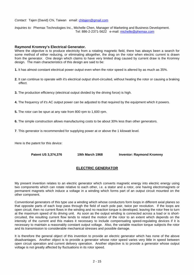
The basic drive/generator unit can be replicated on a single shaft to give increased power, still without increased frictional losses between the drive and the power generation:
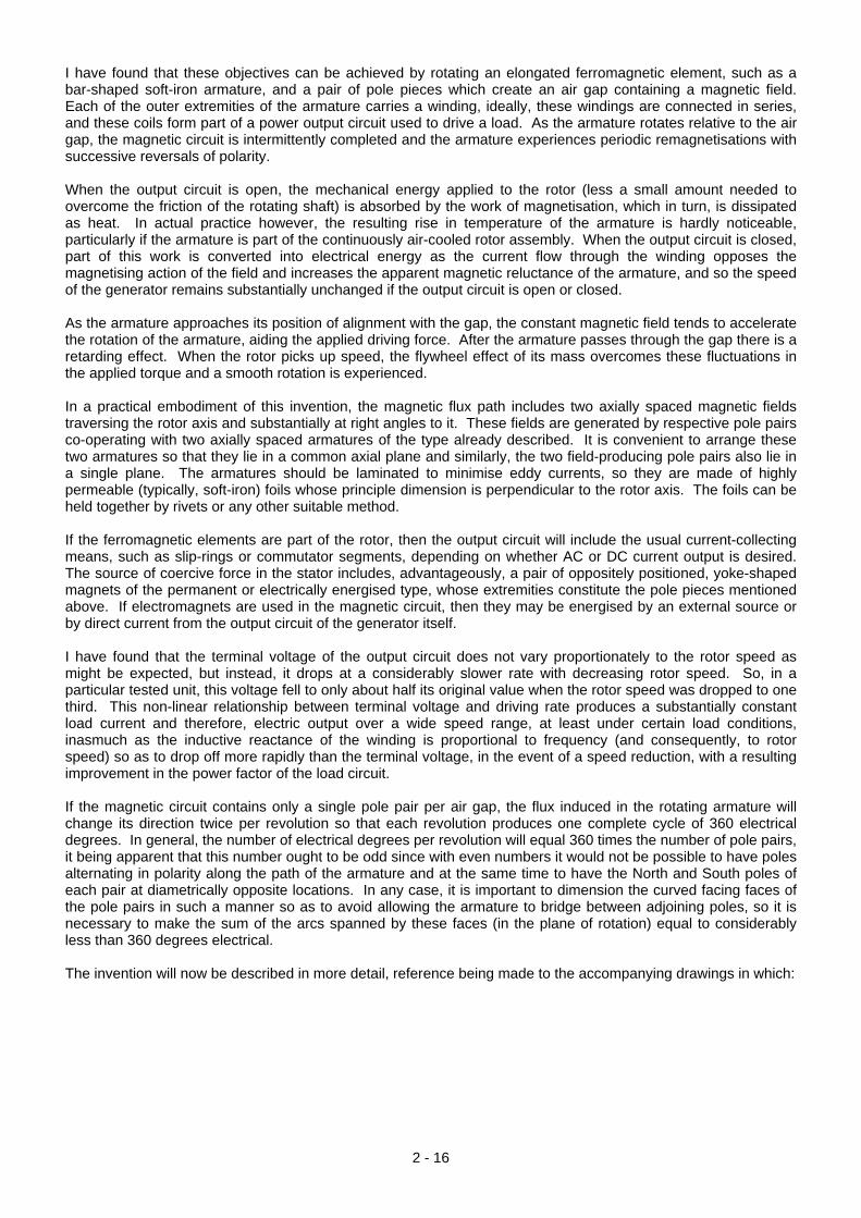
It is unusual to see this technique used as it can be difficult to avoid interaction between the different magnetic fields. However, David has been entirely successful in doing this and the arrangement has no transmission losses between the drive motor and the generator as these are integral components of the system. This system is capable of driving a self-powered air-conditioning unit and a 5 kW proof-of-concept prototype is shown here:
This device is also capable of driving electric lighting and with a 5 kilowatt output self-powered output, it can power most household needs. A typical washing machine has a 2.25 kilowatt maximum electrical draw as does the average tumble-dryer. Most fan-heaters are 3 kilowatts or less when on full output.
2 - 14
If a wind-power generator is already in place, then using the mechanical power of the generator to spin the axle of one of these CHI generators results in a very high-power electricity generation system.
2 - 15
Contact: Tajen (David) Chi, Taiwan email: [email protected] Inquiries to: Phemax Technologies Inc., Michelle Chen, Manager of Marketing and Business Development.
Tel: 886-2-2371-5622 e-mail: [email protected] Raymond Kromrey’s Electrical Generator. Where the objective is to produce electricity from a rotating magnetic field, there has always been a search for some method of either reducing, or eliminating altogether, the drag on the rotor when electric current is drawn from the generator. One design which claims to have very limited drag caused by current draw is the Kromrey design. The main characteristics of this design are said to be: 1. It has almost constant electrical power output even when the rotor speed is altered by as much as 35%. 2. It can continue to operate with it's electrical output short-circuited, without heating the rotor or causing a braking
effect. 3. The production efficiency (electrical output divided by the driving force) is high. 4. The frequency of it's AC output power can be adjusted to that required by the equipment which it powers. 5. The rotor can be spun at any rate from 800 rpm to 1,600 rpm. 6. The simple construction allows manufacturing costs to be about 30% less than other generators. 7. This generator is recommended for supplying power at or above the 1 kilowatt level. Here is the patent for this device:
Patent US 3,374,376 19th March 1968 Inventor: Raymond Kromrey
ELECTRIC GENERATOR My present invention relates to an electric generator which converts magnetic energy into electric energy using two components which can rotate relative to each other, i.e. a stator and a rotor, one having electromagnets or permanent magnets which induce a voltage in a winding which forms part of an output circuit mounted on the other component. Conventional generators of this type use a winding which whose conductors form loops in different axial planes so that opposite parts of each loop pass through the field of each pole pair, twice per revolution. If the loops are open circuit, then no current flows in the winding and no reaction torque is developed, leaving the rotor free to turn at the maximum speed of its driving unit. As soon as the output winding is connected across a load or is short-circuited, the resulting current flow tends to retard the motion of the rotor to an extent which depends on the intensity of the current and this makes it necessary to include compensating speed-regulating devices if it is necessary to maintain a reasonably constant output voltage. Also, the variable reaction torque subjects the rotor and its transmission to considerable mechanical stresses and possible damage. It is therefore the general object of this invention to provide an electric generator which has none of the above disadvantages. Another object is to provide a generator whose rotor speed varies very little in speed between open circuit operation and current delivery operation. Another objective is to provide a generator whose output voltage is not greatly affected by fluctuations in its rotor speed.
2 - 16
I have found that these objectives can be achieved by rotating an elongated ferromagnetic element, such as a bar-shaped soft-iron armature, and a pair of pole pieces which create an air gap containing a magnetic field. Each of the outer extremities of the armature carries a winding, ideally, these windings are connected in series, and these coils form part of a power output circuit used to drive a load. As the armature rotates relative to the air gap, the magnetic circuit is intermittently completed and the armature experiences periodic remagnetisations with successive reversals of polarity. When the output circuit is open, the mechanical energy applied to the rotor (less a small amount needed to overcome the friction of the rotating shaft) is absorbed by the work of magnetisation, which in turn, is dissipated as heat. In actual practice however, the resulting rise in temperature of the armature is hardly noticeable, particularly if the armature is part of the continuously air-cooled rotor assembly. When the output circuit is closed, part of this work is converted into electrical energy as the current flow through the winding opposes the magnetising action of the field and increases the apparent magnetic reluctance of the armature, and so the speed of the generator remains substantially unchanged if the output circuit is open or closed. As the armature approaches its position of alignment with the gap, the constant magnetic field tends to accelerate the rotation of the armature, aiding the applied driving force. After the armature passes through the gap there is a retarding effect. When the rotor picks up speed, the flywheel effect of its mass overcomes these fluctuations in the applied torque and a smooth rotation is experienced. In a practical embodiment of this invention, the magnetic flux path includes two axially spaced magnetic fields traversing the rotor axis and substantially at right angles to it. These fields are generated by respective pole pairs co-operating with two axially spaced armatures of the type already described. It is convenient to arrange these two armatures so that they lie in a common axial plane and similarly, the two field-producing pole pairs also lie in a single plane. The armatures should be laminated to minimise eddy currents, so they are made of highly permeable (typically, soft-iron) foils whose principle dimension is perpendicular to the rotor axis. The foils can be held together by rivets or any other suitable method. If the ferromagnetic elements are part of the rotor, then the output circuit will include the usual current-collecting means, such as slip-rings or commutator segments, depending on whether AC or DC current output is desired. The source of coercive force in the stator includes, advantageously, a pair of oppositely positioned, yoke-shaped magnets of the permanent or electrically energised type, whose extremities constitute the pole pieces mentioned above. If electromagnets are used in the magnetic circuit, then they may be energised by an external source or by direct current from the output circuit of the generator itself. I have found that the terminal voltage of the output circuit does not vary proportionately to the rotor speed as might be expected, but instead, it drops at a considerably slower rate with decreasing rotor speed. So, in a particular tested unit, this voltage fell to only about half its original value when the rotor speed was dropped to one third. This non-linear relationship between terminal voltage and driving rate produces a substantially constant load current and therefore, electric output over a wide speed range, at least under certain load conditions, inasmuch as the inductive reactance of the winding is proportional to frequency (and consequently, to rotor speed) so as to drop off more rapidly than the terminal voltage, in the event of a speed reduction, with a resulting improvement in the power factor of the load circuit. If the magnetic circuit contains only a single pole pair per air gap, the flux induced in the rotating armature will change its direction twice per revolution so that each revolution produces one complete cycle of 360 electrical degrees. In general, the number of electrical degrees per revolution will equal 360 times the number of pole pairs, it being apparent that this number ought to be odd since with even numbers it would not be possible to have poles alternating in polarity along the path of the armature and at the same time to have the North and South poles of each pair at diametrically opposite locations. In any case, it is important to dimension the curved facing faces of the pole pairs in such a manner so as to avoid allowing the armature to bridge between adjoining poles, so it is necessary to make the sum of the arcs spanned by these faces (in the plane of rotation) equal to considerably less than 360 degrees electrical. The invention will now be described in more detail, reference being made to the accompanying drawings in which:
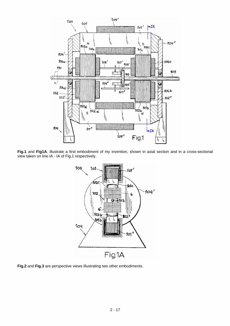
Fig.1 and Fig1A. illustrate a first embodiment of my invention, shown in axial section and in a cross-sectional view taken on line IA - IA of Fig.1 respectively.
Fig.2 and Fig.3 are perspective views illustrating two other embodiments.
2 - 17
2 - 18
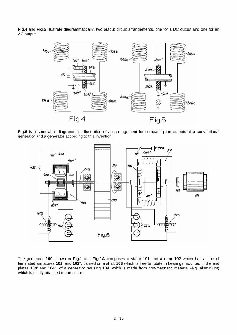
Fig.4 and Fig.5 illustrate diagrammatically, two output circuit arrangements, one for a DC output and one for an AC output.
Fig.6 is a somewhat diagrammatic illustration of an arrangement for comparing the outputs of a conventional generator and a generator according to this invention.
The generator 100 shown in Fig.1 and Fig.1A comprises a stator 101 and a rotor 102 which has a pair of laminated armatures 102' and 102", carried on a shaft 103 which is free to rotate in bearings mounted in the end plates 104' and 104", of a generator housing 104 which is made from non-magnetic material (e.g. aluminium) which is rigidly attached to the stator.
2 - 19
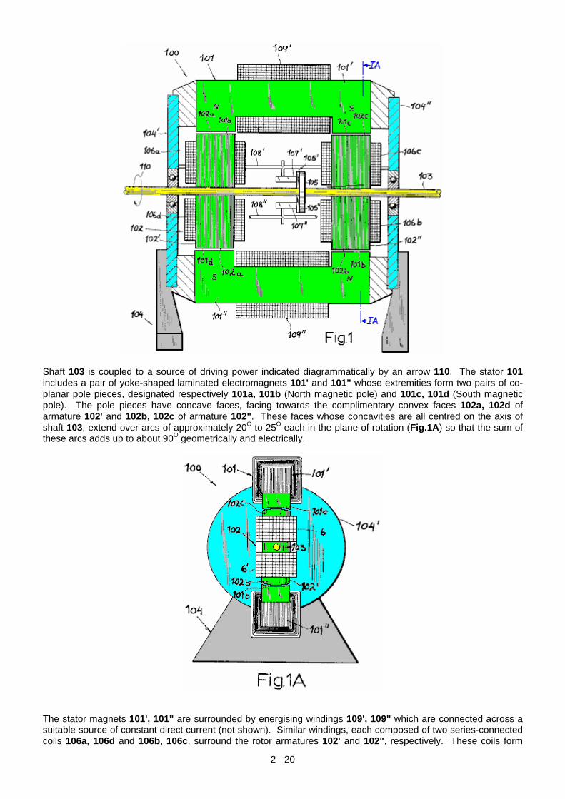
Shaft 103 is coupled to a source of driving power indicated diagrammatically by an arrow 110. The stator 101 includes a pair of yoke-shaped laminated electromagnets 101' and 101" whose extremities form two pairs of co-planar pole pieces, designated respectively 101a, 101b (North magnetic pole) and 101c, 101d (South magnetic pole). The pole pieces have concave faces, facing towards the complimentary convex faces 102a, 102d of armature 102' and 102b, 102c of armature 102". These faces whose concavities are all centred on the axis of shaft 103, extend over arcs of approximately 20O to 25O each in the plane of rotation (Fig.1A) so that the sum of these arcs adds up to about 90O geometrically and electrically.
The stator magnets 101', 101" are surrounded by energising windings 109', 109" which are connected across a suitable source of constant direct current (not shown). Similar windings, each composed of two series-connected coils 106a, 106d and 106b, 106c, surround the rotor armatures 102' and 102", respectively. These coils form
2 - 20
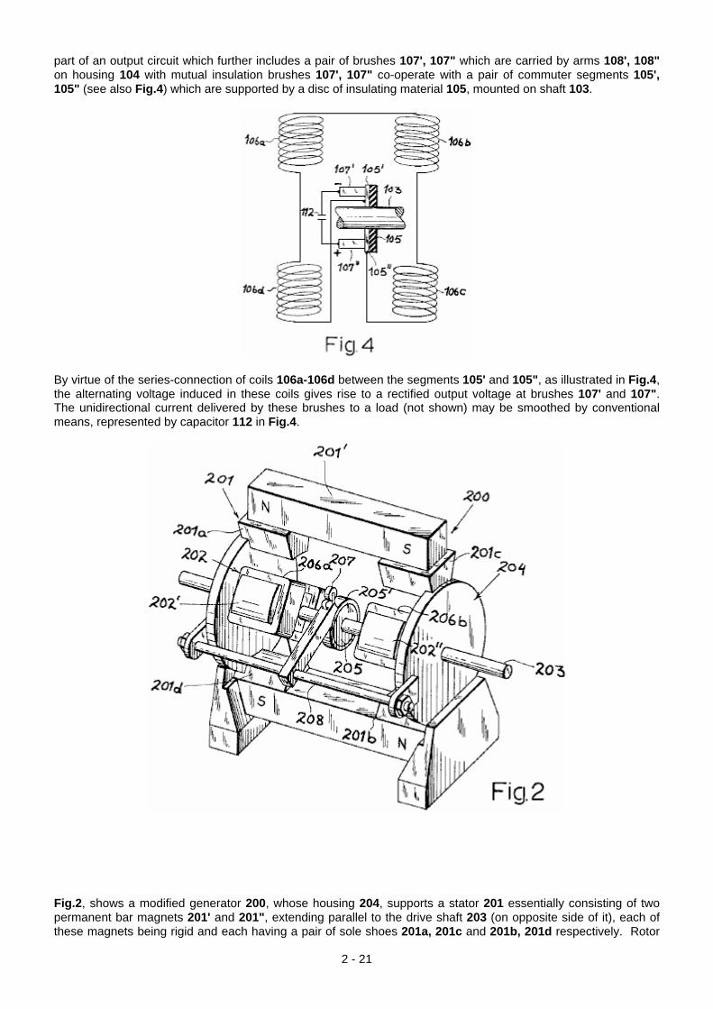
part of an output circuit which further includes a pair of brushes 107', 107" which are carried by arms 108', 108" on housing 104 with mutual insulation brushes 107', 107" co-operate with a pair of commuter segments 105', 105" (see also Fig.4) which are supported by a disc of insulating material 105, mounted on shaft 103.
By virtue of the series-connection of coils 106a-106d between the segments 105' and 105", as illustrated in Fig.4, the alternating voltage induced in these coils gives rise to a rectified output voltage at brushes 107' and 107". The unidirectional current delivered by these brushes to a load (not shown) may be smoothed by conventional means, represented by capacitor 112 in Fig.4.
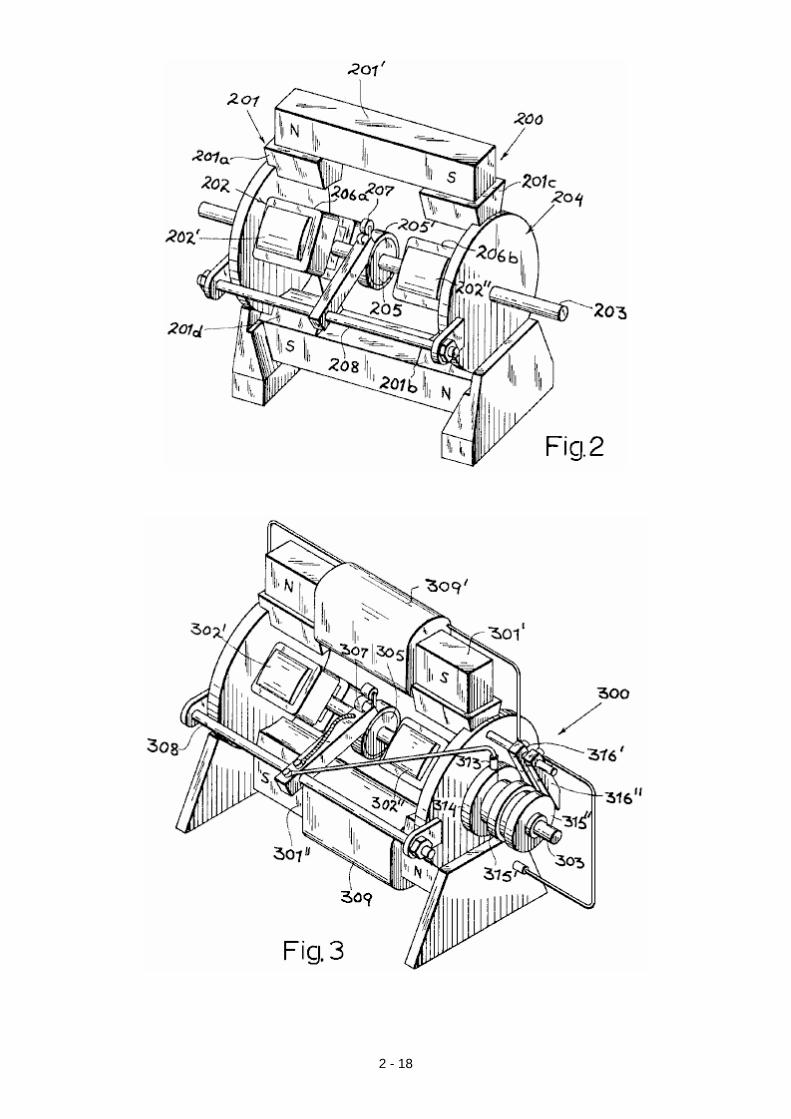
Fig.2, shows a modified generator 200, whose housing 204, supports a stator 201 essentially consisting of two permanent bar magnets 201' and 201", extending parallel to the drive shaft 203 (on opposite side of it), each of these magnets being rigid and each having a pair of sole shoes 201a, 201c and 201b, 201d respectively. Rotor
2 - 21
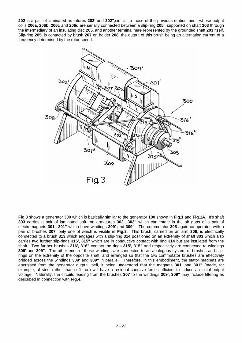
202 is a pair of laminated armatures 202' and 202",similar to those of the previous embodiment, whose output coils 206a, 206b, 206c and 206d are serially connected between a slip-ring 205', supported on shaft 203 through the intermediary of an insulating disc 205, and another terminal here represented by the grounded shaft 203 itself. Slip-ring 205' is contacted by brush 207 on holder 208, the output of this brush being an alternating current of a frequency determined by the rotor speed.
Fig.3 shows a generator 300 which is basically similar to the generator 100 shown in Fig.1 and Fig.1A. It's shaft 303 carries a pair of laminated soft-iron armatures 302', 302" which can rotate in the air gaps of a pair of electromagnets 301', 301" which have windings 309' and 309". The commutator 305 again co-operates with a pair of brushes 307, only one of which is visible in Fig.3. This brush, carried on an arm 308, is electrically connected to a brush 313 which engages with a slip-ring 314 positioned on an extremity of shaft 303 which also carries two further slip-rings 315', 315" which are in conductive contact with ring 314 but are insulated from the shaft. Two further brushes 316', 316" contact the rings 315', 315" and respectively are connected to windings 309' and 309". The other ends of these windings are connected to an analogous system of brushes and slip-rings on the extremity of the opposite shaft, and arranged so that the two commutator brushes are effectively bridged across the windings 309' and 309" in parallel. Therefore, in this embodiment, the stator magnets are energised from the generator output itself, it being understood that the magnets 301' and 301" (made, for example, of steel rather than soft iron) will have a residual coercive force sufficient to induce an initial output voltage. Naturally, the circuits leading from the brushes 307 to the windings 309', 309" may include filtering as described in connection with Fig.4.
2 - 22

Fig.6 shows a test circuit designed to compare the outputs of a generator of this design, such as the unit 100 of Fig.1 and Fig.1A, with a conventional generator 400 of the type having a looped armature 402 which rotates in the gap of a stator magnet 401 which is fitted with energising windings 409', 409". The two generators are interconnected by a common shaft 103 which carries a flywheel 117. This shaft is coupled through a clutch 118 to a drive motor 111 which drives the rotors 402 and 102 of both generators in unison, as indicated by arrow 110. Two batteries 120 and 420, in series with switches 121 and 421, represent the method of supplying direct current to the stator windings 109', 109" and 409', 409" of the two generators. The rectified output of generator 100 is delivered to a load 122, shown here as three incandescent lamps connected in series, and with a combined consumption of 500 watts. Generator 400, provides current into an identical load 422. Two watt meters 123 and 423 have their voltage and current windings connected respectively in shunt and in series with their associated loads 122 and 422, to measure the electric power delivered by each generator. When clutch 118 is engaged, shaft 113 with it's flywheel 117 is brought to an initial driving speed of 1,200 rpm. at which point, the switch 421 in the energising circuit of the conventional generator 400, is closed. The lamps 422 light immediately and the corresponding wattmeter 423 shows an initial output of 500 watts. However, this output drops immediately as the flywheel 117 is decelerated by the braking effect of the magnetic field on armature 402. Next, the procedure is repeated but with switch 421 open and switch 121 closed. This energises generator 100 and the lamps 122 light up, wattmeter 123 showing an output of 500 watts, which remains constant for an indefinite period of time , there being no appreciable deceleration of flywheel 117. When the clutch 118 is released and the rotor speed gradually decreases, the output of generator 100 is still substantially 500 watts at a speed of 900 rpm. and remains as high as 360 watts when the speed dropped further to 600 rpm. In a similar test with a generator of the permanent magnet type, such as the one shown at 200 in Fig.2, a substantially constant output was observed over a range of 1600 to 640 rpm. Teruo Kawai’s COP=1.6 Magnetic Motor. In July 1995, a patent was granted to Teruo Kawai for an electric motor. In the patent, Teruo states that a measured electrical input 19.55 watts produced an output of 62.16 watts, and that is a COP of 3.18. The main sections of that patent are included in the Appendix.
2 - 23
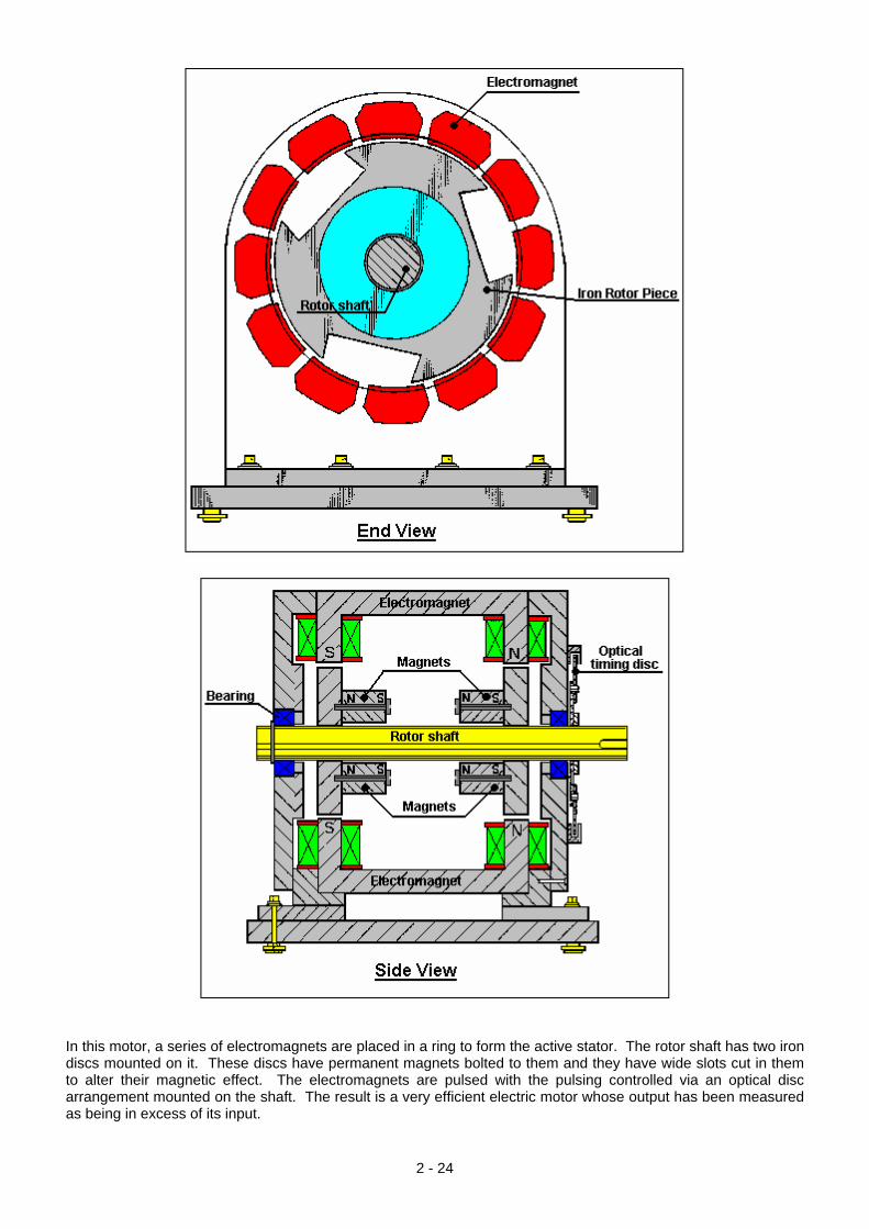
In this motor, a series of electromagnets are placed in a ring to form the active stator. The rotor shaft has two iron discs mounted on it. These discs have permanent magnets bolted to them and they have wide slots cut in them to alter their magnetic effect. The electromagnets are pulsed with the pulsing controlled via an optical disc arrangement mounted on the shaft. The result is a very efficient electric motor whose output has been measured as being in excess of its input.
2 - 24
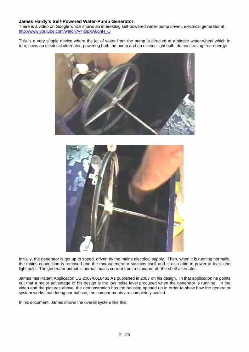
James Hardy’s Self-Powered Water-Pump Generator. There is a video on Google which shows an interesting self-powered water-pump driven, electrical generator at: http://www.youtube.com/watch?v=IGpXA6qhH_Q This is a very simple device where the jet of water from the pump is directed at a simple water-wheel which in turn, spins an electrical alternator, powering both the pump and an electric light bulb, demonstrating free-energy.
Initially, the generator is got up to speed, driven by the mains electrical supply. Then, when it is running normally, the mains connection is removed and the motor/generator sustains itself and is also able to power at least one light bulb. The generator output is normal mains current from a standard off-the-shelf alternator. James has Patent Application US 2007/0018461 A1 published in 2007 on his design. In that application he points out that a major advantage of his design is the low noise level produced when the generator is running. In the video and the pictures above, the demonstration has the housing opened up in order to show how the generator system works, but during normal use, the compartments are completely sealed. In his document, James shows the overall system like this:
2 - 25
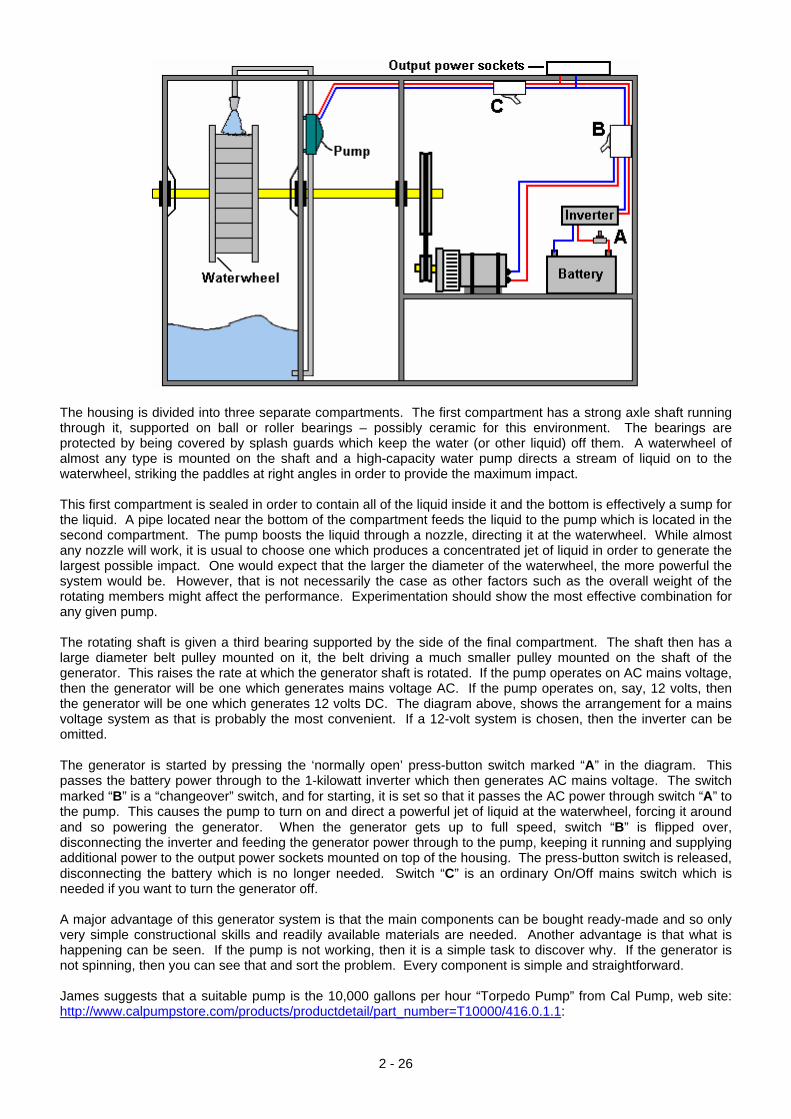
The housing is divided into three separate compartments. The first compartment has a strong axle shaft running through it, supported on ball or roller bearings – possibly ceramic for this environment. The bearings are protected by being covered by splash guards which keep the water (or other liquid) off them. A waterwheel of almost any type is mounted on the shaft and a high-capacity water pump directs a stream of liquid on to the waterwheel, striking the paddles at right angles in order to provide the maximum impact. This first compartment is sealed in order to contain all of the liquid inside it and the bottom is effectively a sump for the liquid. A pipe located near the bottom of the compartment feeds the liquid to the pump which is located in the second compartment. The pump boosts the liquid through a nozzle, directing it at the waterwheel. While almost any nozzle will work, it is usual to choose one which produces a concentrated jet of liquid in order to generate the largest possible impact. One would expect that the larger the diameter of the waterwheel, the more powerful the system would be. However, that is not necessarily the case as other factors such as the overall weight of the rotating members might affect the performance. Experimentation should show the most effective combination for any given pump. The rotating shaft is given a third bearing supported by the side of the final compartment. The shaft then has a large diameter belt pulley mounted on it, the belt driving a much smaller pulley mounted on the shaft of the generator. This raises the rate at which the generator shaft is rotated. If the pump operates on AC mains voltage, then the generator will be one which generates mains voltage AC. If the pump operates on, say, 12 volts, then the generator will be one which generates 12 volts DC. The diagram above, shows the arrangement for a mains voltage system as that is probably the most convenient. If a 12-volt system is chosen, then the inverter can be omitted. The generator is started by pressing the ‘normally open’ press-button switch marked “A” in the diagram. This passes the battery power through to the 1-kilowatt inverter which then generates AC mains voltage. The switch marked “B” is a “changeover” switch, and for starting, it is set so that it passes the AC power through switch “A” to the pump. This causes the pump to turn on and direct a powerful jet of liquid at the waterwheel, forcing it around and so powering the generator. When the generator gets up to full speed, switch “B” is flipped over, disconnecting the inverter and feeding the generator power through to the pump, keeping it running and supplying additional power to the output power sockets mounted on top of the housing. The press-button switch is released, disconnecting the battery which is no longer needed. Switch “C” is an ordinary On/Off mains switch which is needed if you want to turn the generator off. A major advantage of this generator system is that the main components can be bought ready-made and so only very simple constructional skills and readily available materials are needed. Another advantage is that what is happening can be seen. If the pump is not working, then it is a simple task to discover why. If the generator is not spinning, then you can see that and sort the problem. Every component is simple and straightforward. James suggests that a suitable pump is the 10,000 gallons per hour “Torpedo Pump” from Cal Pump, web site: http://www.calpumpstore.com/products/productdetail/part_number=T10000/416.0.1.1:
2 - 26
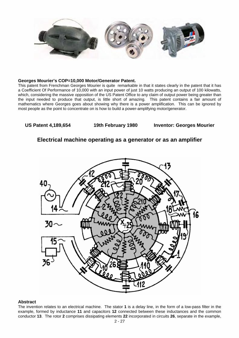
Georges Mourier’s COP=10,000 Motor/Generator Patent. This patent from Frenchman Georges Mourier is quite remarkable in that it states clearly in the patent that it has a Coefficient Of Performance of 10,000 with an input power of just 10 watts producing an output of 100 kilowatts, which, considering the massive opposition of the US Patent Office to any claim of output power being greater than the input needed to produce that output, is little short of amazing. This patent contains a fair amount of mathematics where Georges goes about showing why there is a power amplification. This can be ignored by most people as the point to concentrate on is how to build a power-amplifying motor/generator.
US Patent 4,189,654 19th February 1980 Inventor: Georges Mourier
Electrical machine operating as a generator or as an amplifier
Abstract
2 - 27
The invention relates to an electrical machine. The stator 1 is a delay line, in the form of a low-pass filter in the example, formed by inductance 11 and capacitors 12 connected between these inductances and the common conductor 13. The rotor 2 comprises dissipating elements 22 incorporated in circuits 26, separate in the example,
and having a common point 25. It is put in movement by a motor. The machine operates as a high-gain amplifier having a wide band of high-frequency signals applied to the input 14 of the stator, separated from the output 15 by the decoupling zone 30. High powers are obtainable. Application to installations for testing vibration of industrial equipment and to high-power long wave radio transmission. Description The invention relates to an electrical machine capable of operating as a generator and as an amplifier. The machine comprises a fixed part, or stator, in which moves a moving part designated hereinafter by the term “rotor”, by analogy with the case of machines of the prior art in which the movement in question is a movement of rotation, although this movement may be other than a rotation and in particular a rectilinear translation in the case of the invention. The stator consists of a line having two conductors which have two input terminals and two output terminals; it’s rotor comprises resistive elements under conditions which will be described in detail later. In operation, a wave is propagated between the input terminals and the output terminals in question in this line. Electrical machines are known from U.S. Patent 3,875,484, in which the stator comprises inductances and capacitances incorporated in a transmission line, as in the machines of this invention, along which there is propagated, in operation, an electric wave, but contrary to the case of the invention, this line has only one pair of terminals to which those of the alternating current source are connected. The application of the voltage of this source between these terminals causes the rotation of the rotor of the machine which, as it is operating as a motor, does not have an output. Owing to the structure, a brief indication of which has been given above, the machine of this invention is intended, on the contrary, to operate as a generator or as an amplifier; it has an output constituted by the other pair of terminals of the stator, the rotor being driven by an exterior motor. A better understanding of the invention will be had from the ensuing description with reference to the accompanying Figures which represent:
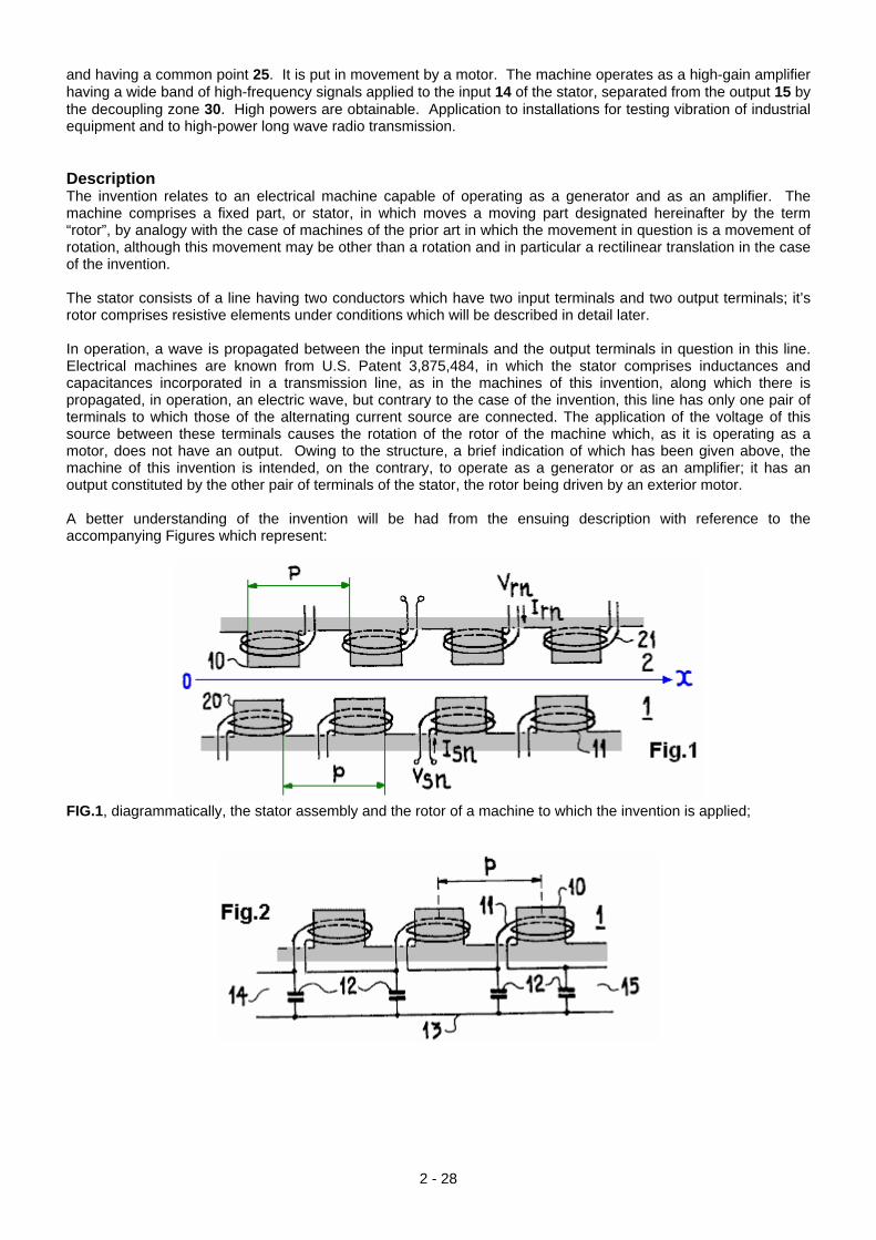
FIG.1, diagrammatically, the stator assembly and the rotor of a machine to which the invention is applied;
2 - 28
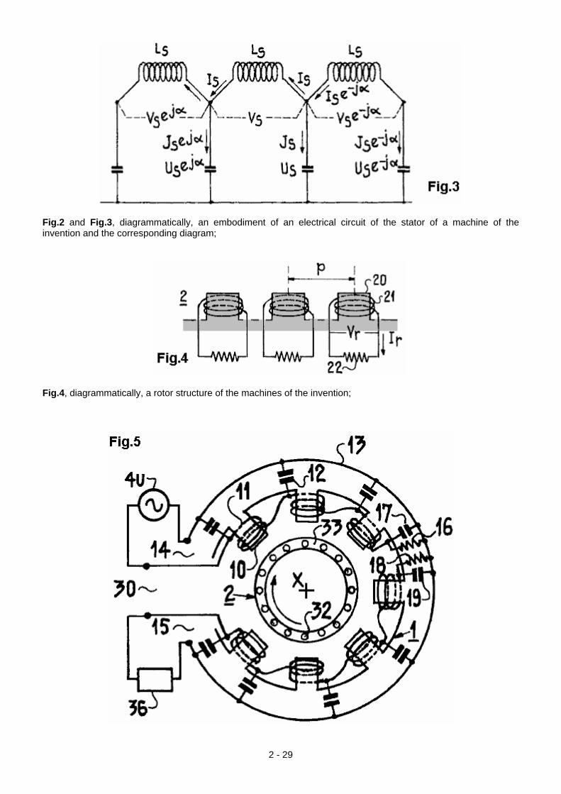
Fig.2 and Fig.3, diagrammatically, an embodiment of an electrical circuit of the stator of a machine of the invention and the corresponding diagram;
Fig.4, diagrammatically, a rotor structure of the machines of the invention;
2 - 29
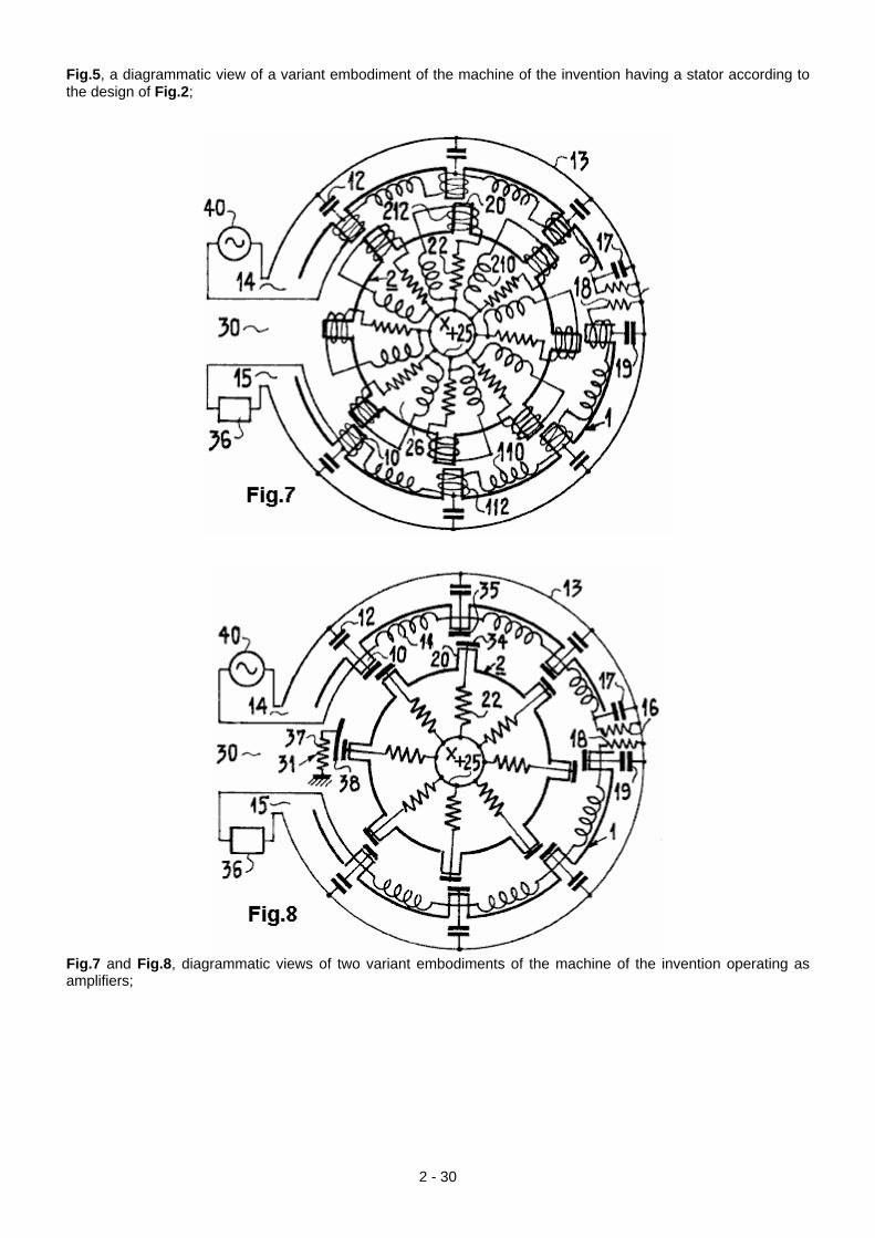
Fig.5, a diagrammatic view of a variant embodiment of the machine of the invention having a stator according to the design of Fig.2;
Fig.7 and Fig.8, diagrammatic views of two variant embodiments of the machine of the invention operating as amplifiers;
2 - 30
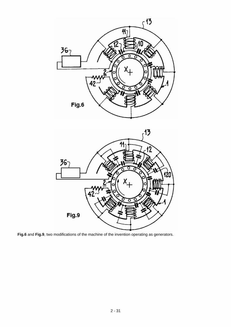
Fig.6 and Fig.9, two modifications of the machine of the invention operating as generators.
2 - 31
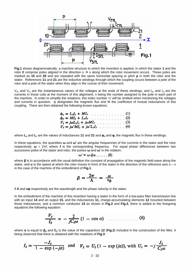
Fig.1 shows diagrammatically, a machine structure to which the invention is applied, in which the stator 1 and the rotor 2 comprise poles aligned in the direction o x along which the rotor movement occurs. These poles are marked as 10 and 20 and are repeated with the same horizontal spacing or pitch p in both the rotor and the stator. References 11 and 21 are the inductive windings through which the coupling occurs between a pole of the rotor and a pole of the stator when they align in the course of their movement. Vsn and Vrn are the instantaneous values of the voltages at the ends of these windings, and Isn and Irn are the currents in those coils at the moment of this alignment, n being the number assigned to the pole in each part of the machine. In order to simplify the notations, this index number ‘n’ will be omitted when mentioning the voltages and currents in question. φ designates the magnetic flux and M the coefficient of mutual inductances of this coupling. There are then obtained the following known equations:
where Ls and Lr are the values of inductances 11 and 21 and φs and φr the magnetic flux in these windings. In these equations, the quantities ω and ω' are the angular frequencies of the currents in the stator and the rotor respectively; ω = 2πf, where f is the corresponding frequency. For equal phase differences between two successive poles of the stator and rotor, the pulses ω and ω' in the relation:
where β is in accordance with the usual definition the constant of propagation of the magnetic field wave along the stator, and u is the speed at which the rotor moves in front of the stator in the direction of the reference axis o – x in the case of the machine of the embodiment of Fig.1.
if Λ and vφ respectively are the wavelength and the phase velocity in the stator. In the embodiment of the machine of this invention having a stator in the form of a low-pass filter transmission line with an input 14 and an output 15, and the inductances 11, charge-accumulating elements 12 mounted between these inductances, and a common conductor 13 as shown in Fig.2 and Fig.3, there is added to the foregoing equations the following equation:
where α is equal to βp and Cs is the value of the capacitors 12 (Fig.2) included in the construction of the filter, it being observed that there is obtained with the notations of Fig.3:
2 - 32
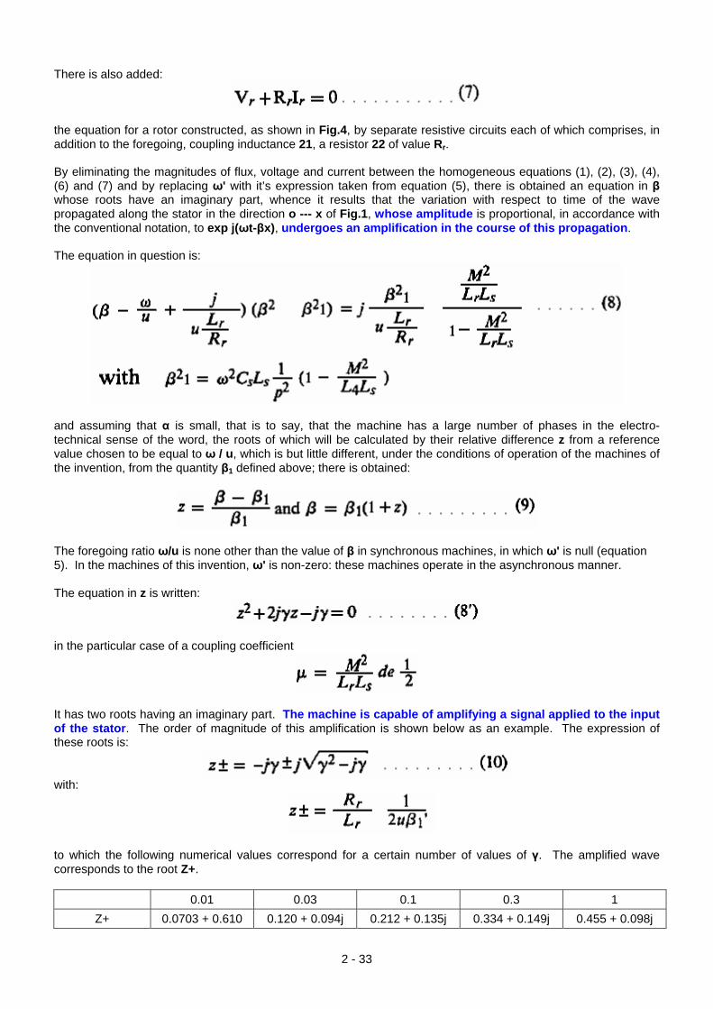
There is also added:
the equation for a rotor constructed, as shown in Fig.4, by separate resistive circuits each of which comprises, in addition to the foregoing, coupling inductance 21, a resistor 22 of value Rr. By eliminating the magnitudes of flux, voltage and current between the homogeneous equations (1), (2), (3), (4), (6) and (7) and by replacing ω' with it’s expression taken from equation (5), there is obtained an equation in β whose roots have an imaginary part, whence it results that the variation with respect to time of the wave propagated along the stator in the direction o --- x of Fig.1, whose amplitude is proportional, in accordance with the conventional notation, to exp j(ωt-βx), undergoes an amplification in the course of this propagation. The equation in question is:
and assuming that α is small, that is to say, that the machine has a large number of phases in the electro-technical sense of the word, the roots of which will be calculated by their relative difference z from a reference value chosen to be equal to ω / u, which is but little different, under the conditions of operation of the machines of the invention, from the quantity β1 defined above; there is obtained:
The foregoing ratio ω/u is none other than the value of β in synchronous machines, in which ω' is null (equation 5). In the machines of this invention, ω' is non-zero: these machines operate in the asynchronous manner. The equation in z is written:
in the particular case of a coupling coefficient
It has two roots having an imaginary part. The machine is capable of amplifying a signal applied to the input of the stator. The order of magnitude of this amplification is shown below as an example. The expression of these roots is:
with:
to which the following numerical values correspond for a certain number of values of γ. The amplified wave corresponds to the root Z+.
0.01 0.03 0.1 0.3 1 Z+ 0.0703 + 0.610 0.120 + 0.094j 0.212 + 0.135j 0.334 + 0.149j 0.455 + 0.098j
2 - 33
The gain “g” in power per unit length of the stator is, according to equation (9) is:
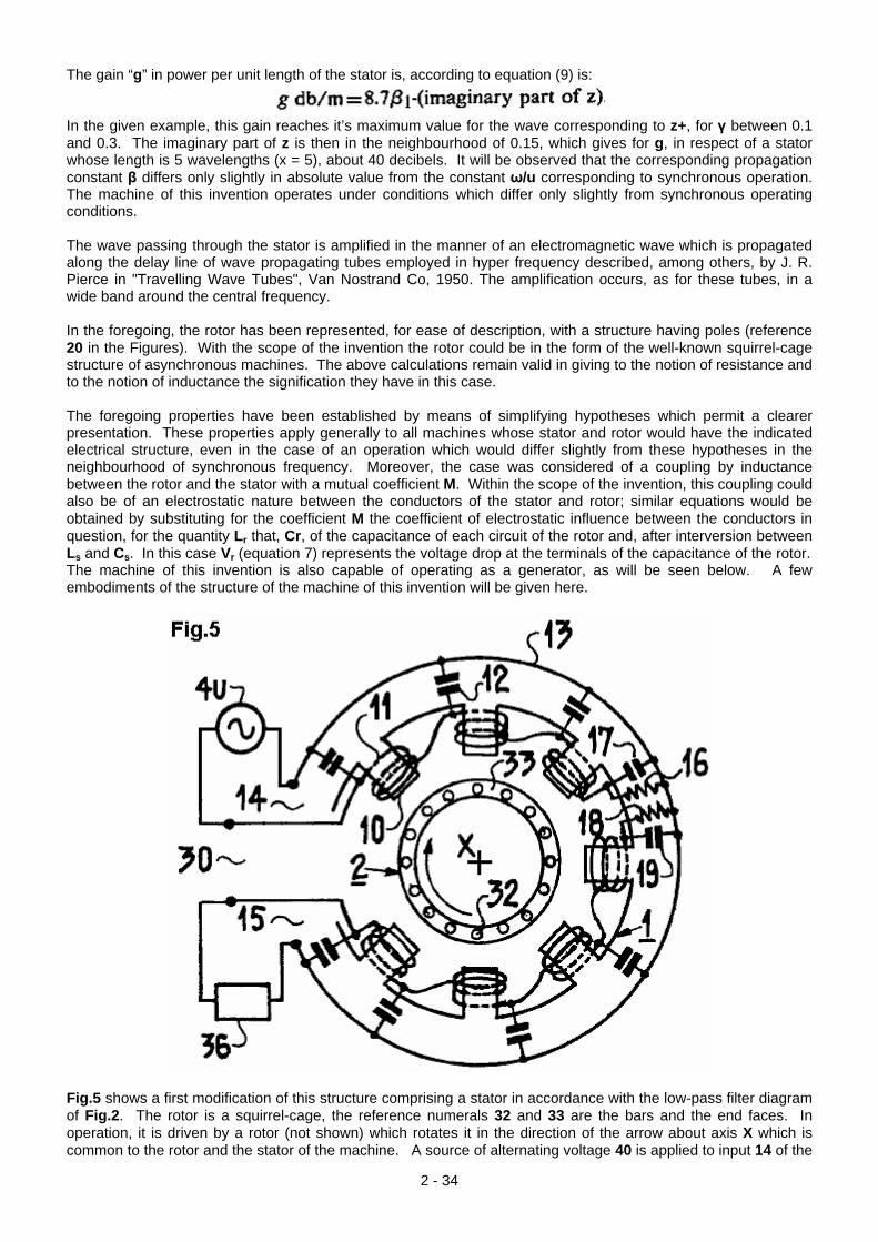
In the given example, this gain reaches it’s maximum value for the wave corresponding to z+, for γ between 0.1 and 0.3. The imaginary part of z is then in the neighbourhood of 0.15, which gives for g, in respect of a stator whose length is 5 wavelengths (x = 5), about 40 decibels. It will be observed that the corresponding propagation constant β differs only slightly in absolute value from the constant ω/u corresponding to synchronous operation. The machine of this invention operates under conditions which differ only slightly from synchronous operating conditions. The wave passing through the stator is amplified in the manner of an electromagnetic wave which is propagated along the delay line of wave propagating tubes employed in hyper frequency described, among others, by J. R. Pierce in "Travelling Wave Tubes", Van Nostrand Co, 1950. The amplification occurs, as for these tubes, in a wide band around the central frequency. In the foregoing, the rotor has been represented, for ease of description, with a structure having poles (reference 20 in the Figures). With the scope of the invention the rotor could be in the form of the well-known squirrel-cage structure of asynchronous machines. The above calculations remain valid in giving to the notion of resistance and to the notion of inductance the signification they have in this case. The foregoing properties have been established by means of simplifying hypotheses which permit a clearer presentation. These properties apply generally to all machines whose stator and rotor would have the indicated electrical structure, even in the case of an operation which would differ slightly from these hypotheses in the neighbourhood of synchronous frequency. Moreover, the case was considered of a coupling by inductance between the rotor and the stator with a mutual coefficient M. Within the scope of the invention, this coupling could also be of an electrostatic nature between the conductors of the stator and rotor; similar equations would be obtained by substituting for the coefficient M the coefficient of electrostatic influence between the conductors in question, for the quantity Lr that, Cr, of the capacitance of each circuit of the rotor and, after interversion between Ls and Cs. In this case Vr (equation 7) represents the voltage drop at the terminals of the capacitance of the rotor. The machine of this invention is also capable of operating as a generator, as will be seen below. A few embodiments of the structure of the machine of this invention will be given here.
Fig.5 shows a first modification of this structure comprising a stator in accordance with the low-pass filter diagram of Fig.2. The rotor is a squirrel-cage, the reference numerals 32 and 33 are the bars and the end faces. In operation, it is driven by a rotor (not shown) which rotates it in the direction of the arrow about axis X which is common to the rotor and the stator of the machine. A source of alternating voltage 40 is applied to input 14 of the
2 - 34
stator, and applied to the output 15 is a load 36, the impedance of which is equal to the characteristic impedance of the line of which the stator is part. In this arrangement of revolution about the axis X, a decoupling zone 30 separates the input and output of the stator. Further, in this zone, and in order to avoid any risk of coupling between input and output of the stator by the circuits of the rotor, there is provided any damping device considered necessary, an embodiment of which is given below. The different elements of the filter constituting the stator are damped by the resistors 16, and 18 which are connected as shown in the Figure between the windings 11 and the conductor 13 common to the terminals of the capacitors 17 and 19. Such a machine operates as an amplifier of the signal applied to the input of the stator with a gain which is of the order of 40 db in the numerical example given above. Such machines may be used as supply sources for high-power vibrators for the testing of industrial equipment of all kinds. They have the advantage over presently-known installations of this type of avoiding the steep leading edges and the high frequencies which result in their spectrum. Output powers of 100 kilowatts may be obtained with 10 watts applied at the input, with frequencies ranging up to 50 kHz. The same machine may be used as a high-power amplifier in radio broadcasting.
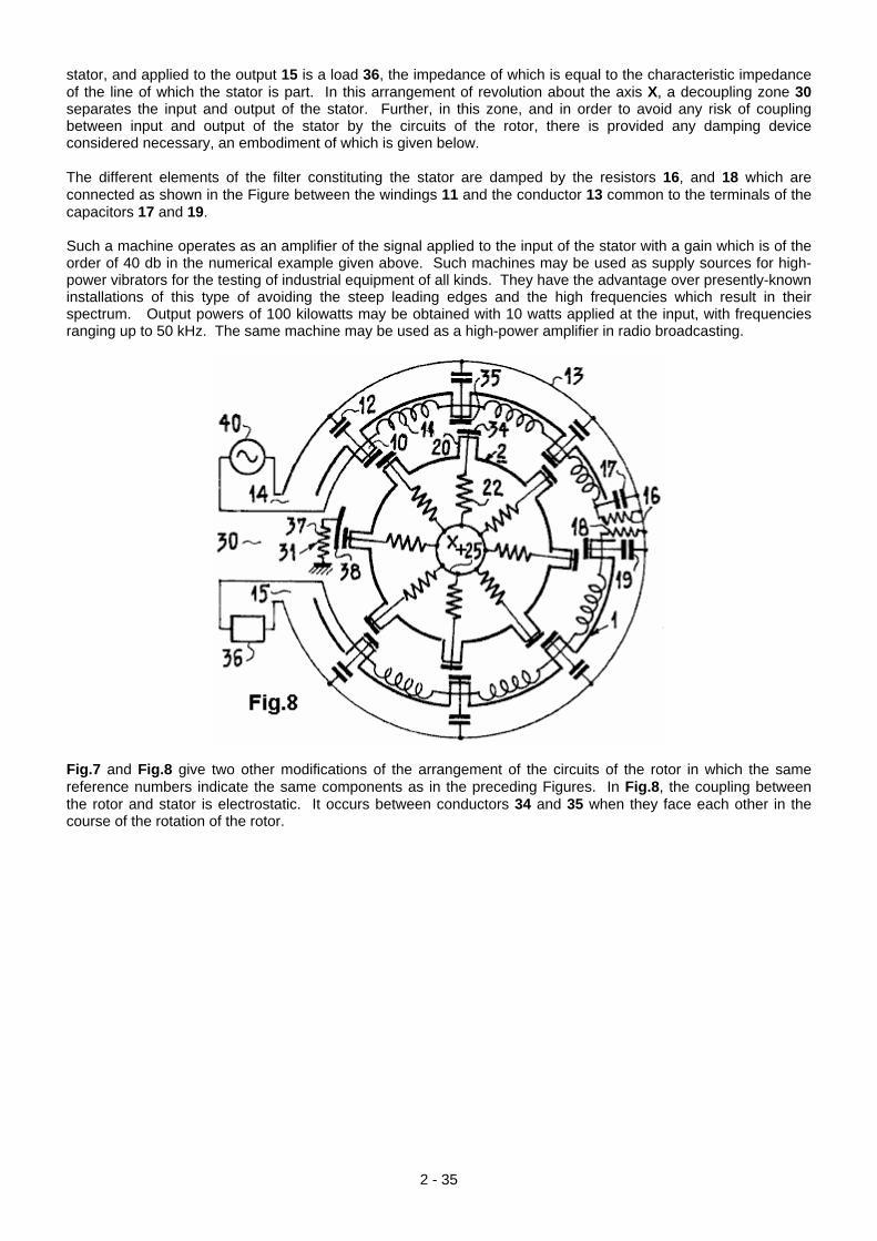
Fig.7 and Fig.8 give two other modifications of the arrangement of the circuits of the rotor in which the same reference numbers indicate the same components as in the preceding Figures. In Fig.8, the coupling between the rotor and stator is electrostatic. It occurs between conductors 34 and 35 when they face each other in the course of the rotation of the rotor.
2 - 35
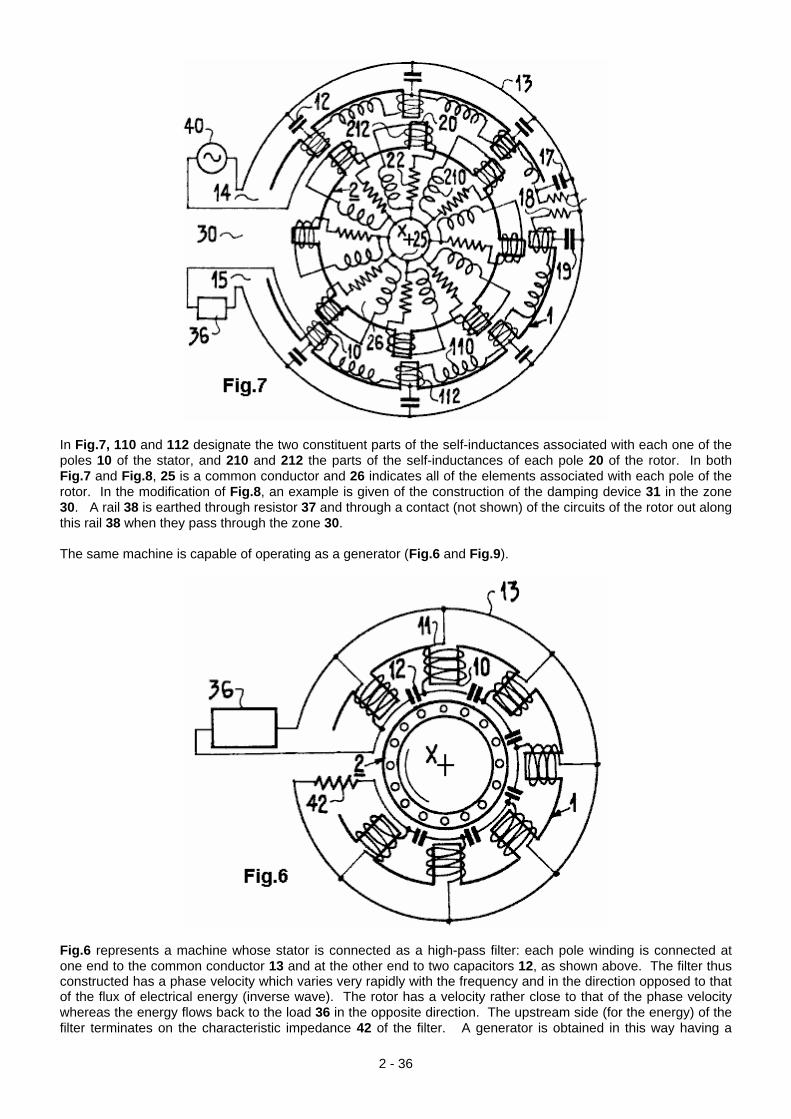
In Fig.7, 110 and 112 designate the two constituent parts of the self-inductances associated with each one of the poles 10 of the stator, and 210 and 212 the parts of the self-inductances of each pole 20 of the rotor. In both Fig.7 and Fig.8, 25 is a common conductor and 26 indicates all of the elements associated with each pole of the rotor. In the modification of Fig.8, an example is given of the construction of the damping device 31 in the zone 30. A rail 38 is earthed through resistor 37 and through a contact (not shown) of the circuits of the rotor out along this rail 38 when they pass through the zone 30. The same machine is capable of operating as a generator (Fig.6 and Fig.9).
Fig.6 represents a machine whose stator is connected as a high-pass filter: each pole winding is connected at one end to the common conductor 13 and at the other end to two capacitors 12, as shown above. The filter thus constructed has a phase velocity which varies very rapidly with the frequency and in the direction opposed to that of the flux of electrical energy (inverse wave). The rotor has a velocity rather close to that of the phase velocity whereas the energy flows back to the load 36 in the opposite direction. The upstream side (for the energy) of the filter terminates on the characteristic impedance 42 of the filter. A generator is obtained in this way having a
2 - 36
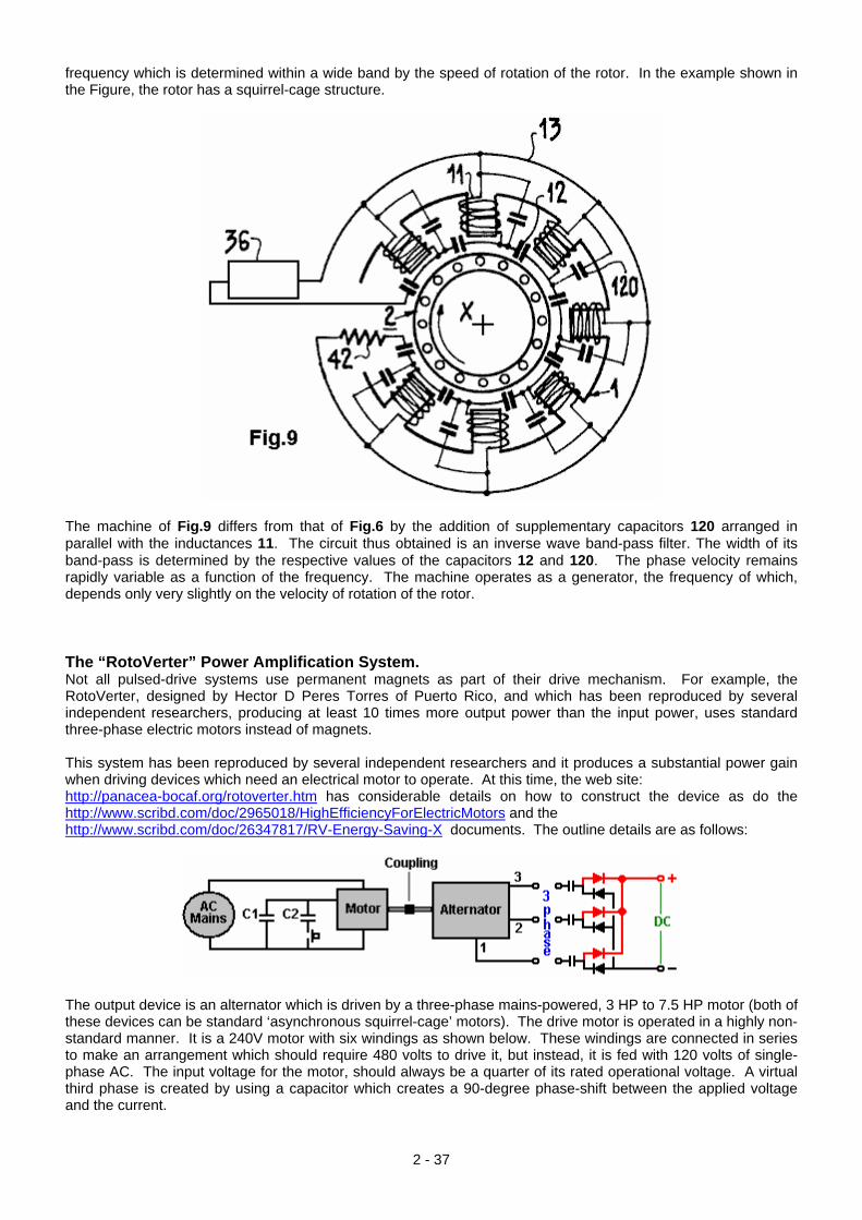
frequency which is determined within a wide band by the speed of rotation of the rotor. In the example shown in the Figure, the rotor has a squirrel-cage structure.
The machine of Fig.9 differs from that of Fig.6 by the addition of supplementary capacitors 120 arranged in parallel with the inductances 11. The circuit thus obtained is an inverse wave band-pass filter. The width of its band-pass is determined by the respective values of the capacitors 12 and 120. The phase velocity remains rapidly variable as a function of the frequency. The machine operates as a generator, the frequency of which, depends only very slightly on the velocity of rotation of the rotor. The “RotoVerter” Power Amplification System. Not all pulsed-drive systems use permanent magnets as part of their drive mechanism. For example, the RotoVerter, designed by Hector D Peres Torres of Puerto Rico, and which has been reproduced by several independent researchers, producing at least 10 times more output power than the input power, uses standard three-phase electric motors instead of magnets. This system has been reproduced by several independent researchers and it produces a substantial power gain when driving devices which need an electrical motor to operate. At this time, the web site: http://panacea-bocaf.org/rotoverter.htm has considerable details on how to construct the device as do the http://www.scribd.com/doc/2965018/HighEfficiencyForElectricMotors and the http://www.scribd.com/doc/26347817/RV-Energy-Saving-X documents. The outline details are as follows:
The output device is an alternator which is driven by a three-phase mains-powered, 3 HP to 7.5 HP motor (both of these devices can be standard ‘asynchronous squirrel-cage’ motors). The drive motor is operated in a highly non-standard manner. It is a 240V motor with six windings as shown below. These windings are connected in series to make an arrangement which should require 480 volts to drive it, but instead, it is fed with 120 volts of single-phase AC. The input voltage for the motor, should always be a quarter of its rated operational voltage. A virtual third phase is created by using a capacitor which creates a 90-degree phase-shift between the applied voltage and the current.
2 - 37
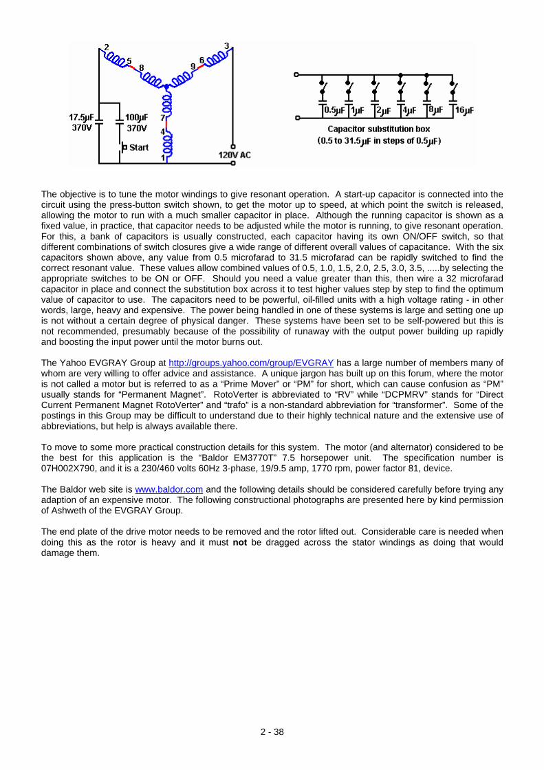
The objective is to tune the motor windings to give resonant operation. A start-up capacitor is connected into the circuit using the press-button switch shown, to get the motor up to speed, at which point the switch is released, allowing the motor to run with a much smaller capacitor in place. Although the running capacitor is shown as a fixed value, in practice, that capacitor needs to be adjusted while the motor is running, to give resonant operation. For this, a bank of capacitors is usually constructed, each capacitor having its own ON/OFF switch, so that different combinations of switch closures give a wide range of different overall values of capacitance. With the six capacitors shown above, any value from 0.5 microfarad to 31.5 microfarad can be rapidly switched to find the correct resonant value. These values allow combined values of 0.5, 1.0, 1.5, 2.0, 2.5, 3.0, 3.5, .....by selecting the appropriate switches to be ON or OFF. Should you need a value greater than this, then wire a 32 microfarad capacitor in place and connect the substitution box across it to test higher values step by step to find the optimum value of capacitor to use. The capacitors need to be powerful, oil-filled units with a high voltage rating - in other words, large, heavy and expensive. The power being handled in one of these systems is large and setting one up is not without a certain degree of physical danger. These systems have been set to be self-powered but this is not recommended, presumably because of the possibility of runaway with the output power building up rapidly and boosting the input power until the motor burns out. The Yahoo EVGRAY Group at http://groups.yahoo.com/group/EVGRAY has a large number of members many of whom are very willing to offer advice and assistance. A unique jargon has built up on this forum, where the motor is not called a motor but is referred to as a “Prime Mover” or “PM” for short, which can cause confusion as “PM” usually stands for “Permanent Magnet”. RotoVerter is abbreviated to “RV” while “DCPMRV” stands for “Direct Current Permanent Magnet RotoVerter” and “trafo” is a non-standard abbreviation for “transformer”. Some of the postings in this Group may be difficult to understand due to their highly technical nature and the extensive use of abbreviations, but help is always available there. To move to some more practical construction details for this system. The motor (and alternator) considered to be the best for this application is the “Baldor EM3770T” 7.5 horsepower unit. The specification number is 07H002X790, and it is a 230/460 volts 60Hz 3-phase, 19/9.5 amp, 1770 rpm, power factor 81, device. The Baldor web site is www.baldor.com and the following details should be considered carefully before trying any adaption of an expensive motor. The following constructional photographs are presented here by kind permission of Ashweth of the EVGRAY Group. The end plate of the drive motor needs to be removed and the rotor lifted out. Considerable care is needed when doing this as the rotor is heavy and it must not be dragged across the stator windings as doing that would damage them.
2 - 38
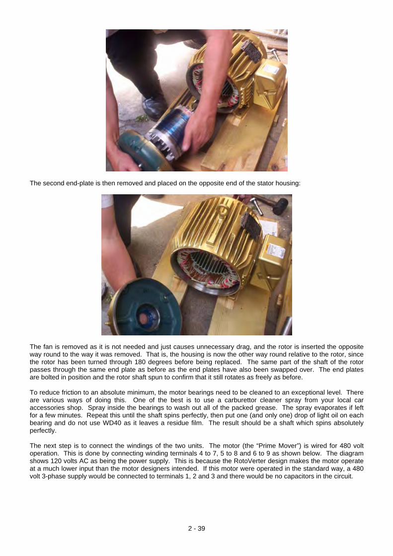
The second end-plate is then removed and placed on the opposite end of the stator housing:
The fan is removed as it is not needed and just causes unnecessary drag, and the rotor is inserted the opposite way round to the way it was removed. That is, the housing is now the other way round relative to the rotor, since the rotor has been turned through 180 degrees before being replaced. The same part of the shaft of the rotor passes through the same end plate as before as the end plates have also been swapped over. The end plates are bolted in position and the rotor shaft spun to confirm that it still rotates as freely as before. To reduce friction to an absolute minimum, the motor bearings need to be cleaned to an exceptional level. There are various ways of doing this. One of the best is to use a carburettor cleaner spray from your local car accessories shop. Spray inside the bearings to wash out all of the packed grease. The spray evaporates if left for a few minutes. Repeat this until the shaft spins perfectly, then put one (and only one) drop of light oil on each bearing and do not use WD40 as it leaves a residue film. The result should be a shaft which spins absolutely perfectly. The next step is to connect the windings of the two units. The motor (the “Prime Mover”) is wired for 480 volt operation. This is done by connecting winding terminals 4 to 7, 5 to 8 and 6 to 9 as shown below. The diagram shows 120 volts AC as being the power supply. This is because the RotoVerter design makes the motor operate at a much lower input than the motor designers intended. If this motor were operated in the standard way, a 480 volt 3-phase supply would be connected to terminals 1, 2 and 3 and there would be no capacitors in the circuit.
2 - 39
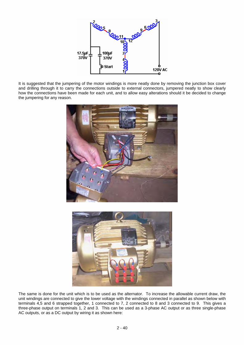
It is suggested that the jumpering of the motor windings is more neatly done by removing the junction box cover and drilling through it to carry the connections outside to external connectors, jumpered neatly to show clearly how the connections have been made for each unit, and to allow easy alterations should it be decided to change the jumpering for any reason.
The same is done for the unit which is to be used as the alternator. To increase the allowable current draw, the unit windings are connected to give the lower voltage with the windings connected in parallel as shown below with terminals 4,5 and 6 strapped together, 1 connected to 7, 2 connected to 8 and 3 connected to 9. This gives a three-phase output on terminals 1, 2 and 3. This can be used as a 3-phase AC output or as three single-phase AC outputs, or as a DC output by wiring it as shown here:
2 - 40
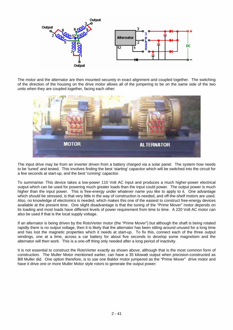
The motor and the alternator are then mounted securely in exact alignment and coupled together. The switching of the direction of the housing on the drive motor allows all of the jumpering to be on the same side of the two units when they are coupled together, facing each other:
The input drive may be from an inverter driven from a battery charged via a solar panel. The system how needs to be ‘tuned’ and tested. This involves finding the best ‘starting’ capacitor which will be switched into the circuit for a few seconds at start-up, and the best ‘running’ capacitor. To summarise: This device takes a low-power 110 Volt AC input and produces a much higher-power electrical output which can be used for powering much greater loads than the input could power. The output power is much higher than the input power. This is free-energy under whatever name you like to apply to it. One advantage which should be stressed, is that very little in the way of construction is needed, and off-the-shelf motors are used. Also, no knowledge of electronics is needed, which makes this one of the easiest to construct free-energy devices available at the present time. One slight disadvantage is that the tuning of the “Prime Mover” motor depends on its loading and most loads have different levels of power requirement from time to time. A 220 Volt AC motor can also be used if that is the local supply voltage. If an alternator is being driven by the RotoVerter motor (the “Prime Mover”) but although the shaft is being rotated rapidly there is no output voltage, then it is likely that the alternator has been sitting around unused for a long time and has lost the magnetic properties which it needs at start-up. To fix this, connect each of the three output windings, one at a time, across a car battery for about five seconds to develop some magnetism and the alternator will then work. This is a one-off thing only needed after a long period of inactivity. It is not essential to construct the RotoVerter exactly as shown above, although that is the most common form of construction. The Muller Motor mentioned earlier, can have a 35 kilowatt output when precision-constructed as Bill Muller did. One option therefore, is to use one Baldor motor jumpered as the “Prime Mover” drive motor and have it drive one or more Muller Motor style rotors to generate the output power:
2 - 41
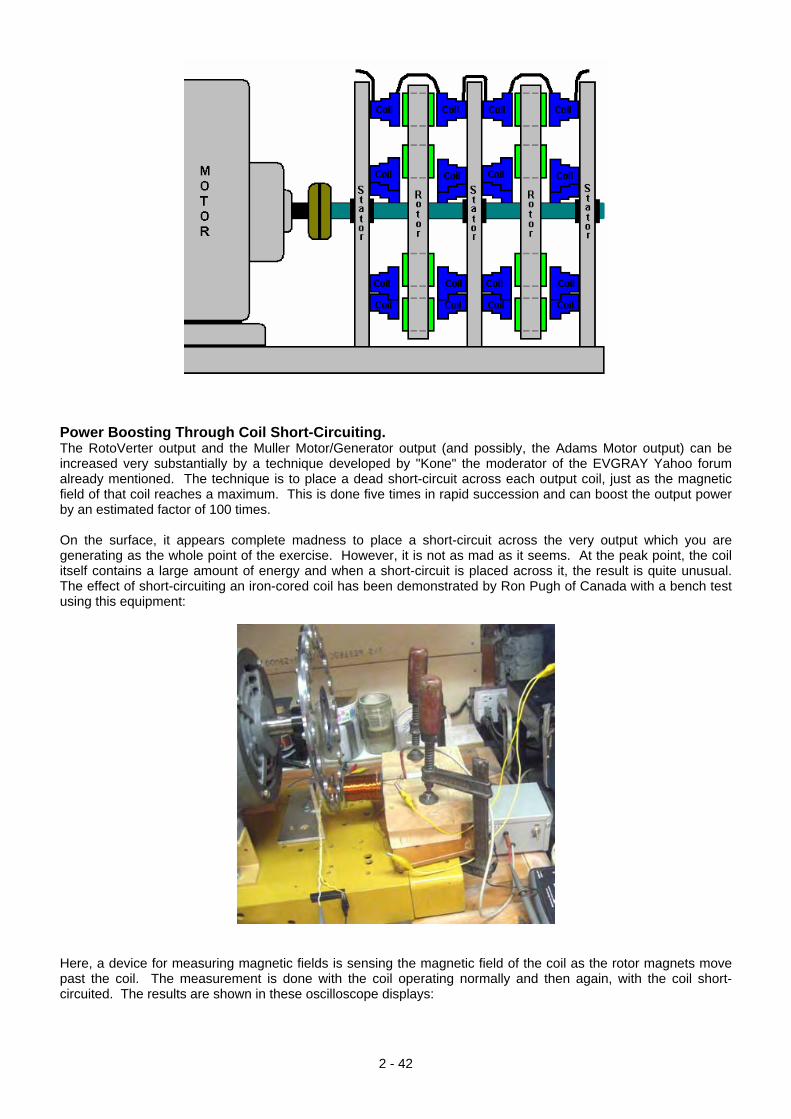
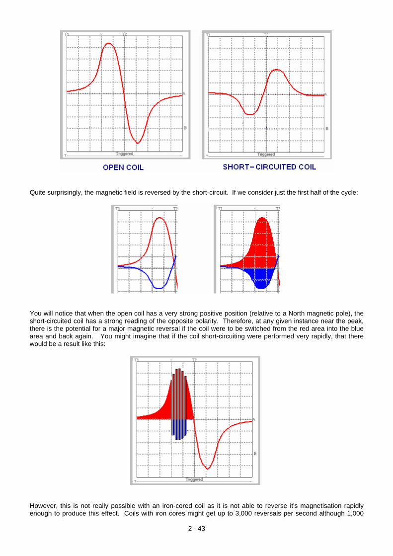
Power Boosting Through Coil Short-Circuiting. The RotoVerter output and the Muller Motor/Generator output (and possibly, the Adams Motor output) can be increased very substantially by a technique developed by "Kone" the moderator of the EVGRAY Yahoo forum already mentioned. The technique is to place a dead short-circuit across each output coil, just as the magnetic field of that coil reaches a maximum. This is done five times in rapid succession and can boost the output power by an estimated factor of 100 times. On the surface, it appears complete madness to place a short-circuit across the very output which you are generating as the whole point of the exercise. However, it is not as mad as it seems. At the peak point, the coil itself contains a large amount of energy and when a short-circuit is placed across it, the result is quite unusual. The effect of short-circuiting an iron-cored coil has been demonstrated by Ron Pugh of Canada with a bench test using this equipment:
Here, a device for measuring magnetic fields is sensing the magnetic field of the coil as the rotor magnets move past the coil. The measurement is done with the coil operating normally and then again, with the coil short-circuited. The results are shown in these oscilloscope displays:
2 - 42
Quite surprisingly, the magnetic field is reversed by the short-circuit. If we consider just the first half of the cycle:
You will notice that when the open coil has a very strong positive position (relative to a North magnetic pole), the short-circuited coil has a strong reading of the opposite polarity. Therefore, at any given instance near the peak, there is the potential for a major magnetic reversal if the coil were to be switched from the red area into the blue area and back again. You might imagine that if the coil short-circuiting were performed very rapidly, that there would be a result like this:
However, this is not really possible with an iron-cored coil as it is not able to reverse it's magnetisation rapidly enough to produce this effect. Coils with iron cores might get up to 3,000 reversals per second although 1,000
2 - 43
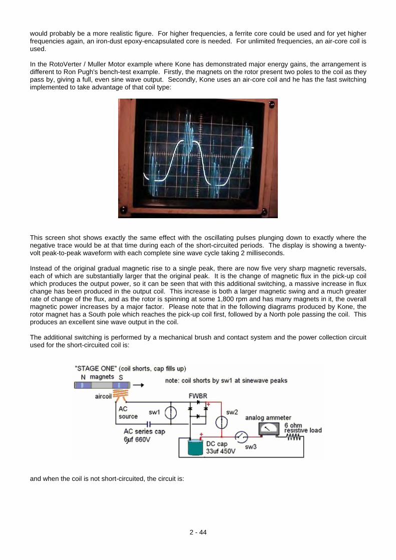
would probably be a more realistic figure. For higher frequencies, a ferrite core could be used and for yet higher frequencies again, an iron-dust epoxy-encapsulated core is needed. For unlimited frequencies, an air-core coil is used. In the RotoVerter / Muller Motor example where Kone has demonstrated major energy gains, the arrangement is different to Ron Pugh's bench-test example. Firstly, the magnets on the rotor present two poles to the coil as they pass by, giving a full, even sine wave output. Secondly, Kone uses an air-core coil and he has the fast switching implemented to take advantage of that coil type:
This screen shot shows exactly the same effect with the oscillating pulses plunging down to exactly where the negative trace would be at that time during each of the short-circuited periods. The display is showing a twenty-volt peak-to-peak waveform with each complete sine wave cycle taking 2 milliseconds. Instead of the original gradual magnetic rise to a single peak, there are now five very sharp magnetic reversals, each of which are substantially larger that the original peak. It is the change of magnetic flux in the pick-up coil which produces the output power, so it can be seen that with this additional switching, a massive increase in flux change has been produced in the output coil. This increase is both a larger magnetic swing and a much greater rate of change of the flux, and as the rotor is spinning at some 1,800 rpm and has many magnets in it, the overall magnetic power increases by a major factor. Please note that in the following diagrams produced by Kone, the rotor magnet has a South pole which reaches the pick-up coil first, followed by a North pole passing the coil. This produces an excellent sine wave output in the coil. The additional switching is performed by a mechanical brush and contact system and the power collection circuit used for the short-circuited coil is:
and when the coil is not short-circuited, the circuit is:
2 - 44
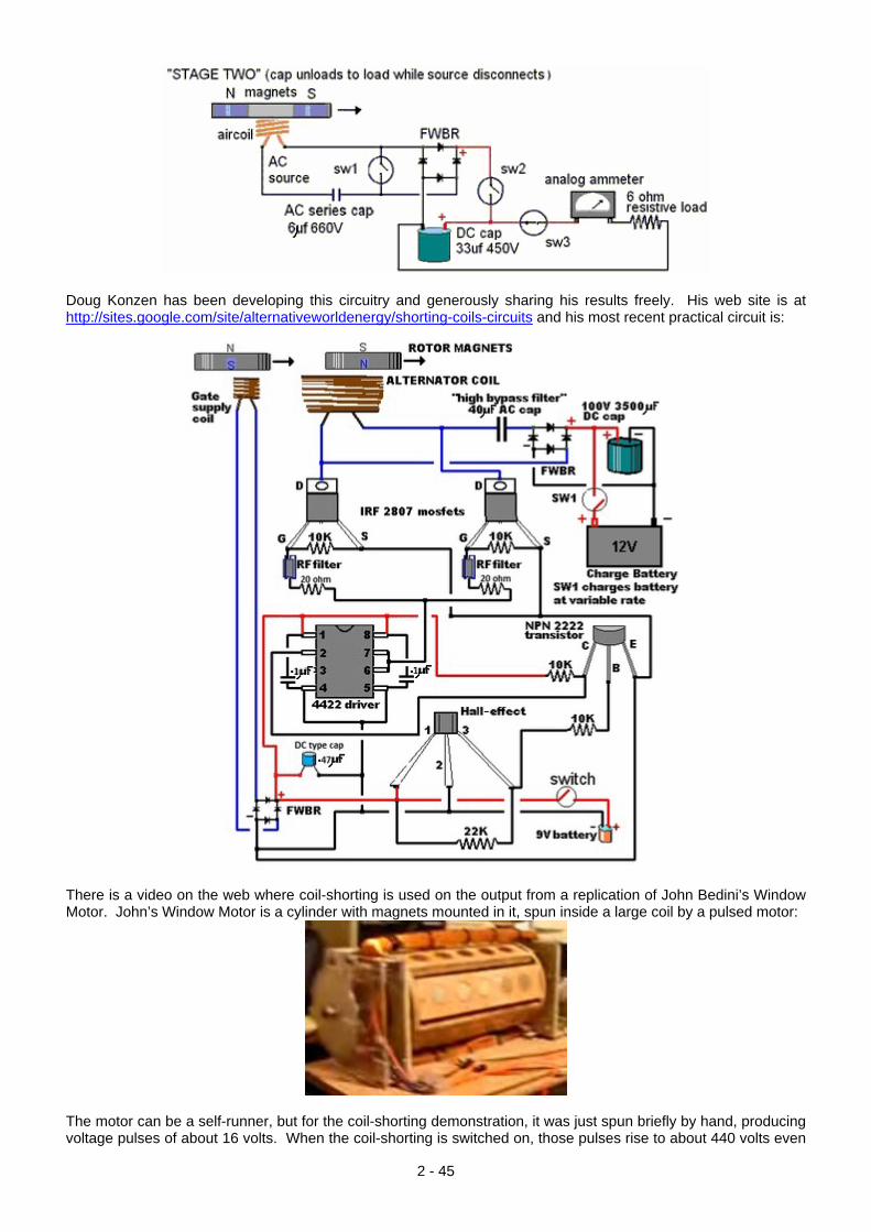
Doug Konzen has been developing this circuitry and generously sharing his results freely. His web site is at http://sites.google.com/site/alternativeworldenergy/shorting-coils-circuits and his most recent practical circuit is:
There is a video on the web where coil-shorting is used on the output from a replication of John Bedini’s Window Motor. John’s Window Motor is a cylinder with magnets mounted in it, spun inside a large coil by a pulsed motor:
The motor can be a self-runner, but for the coil-shorting demonstration, it was just spun briefly by hand, producing voltage pulses of about 16 volts. When the coil-shorting is switched on, those pulses rise to about 440 volts even
2 - 45
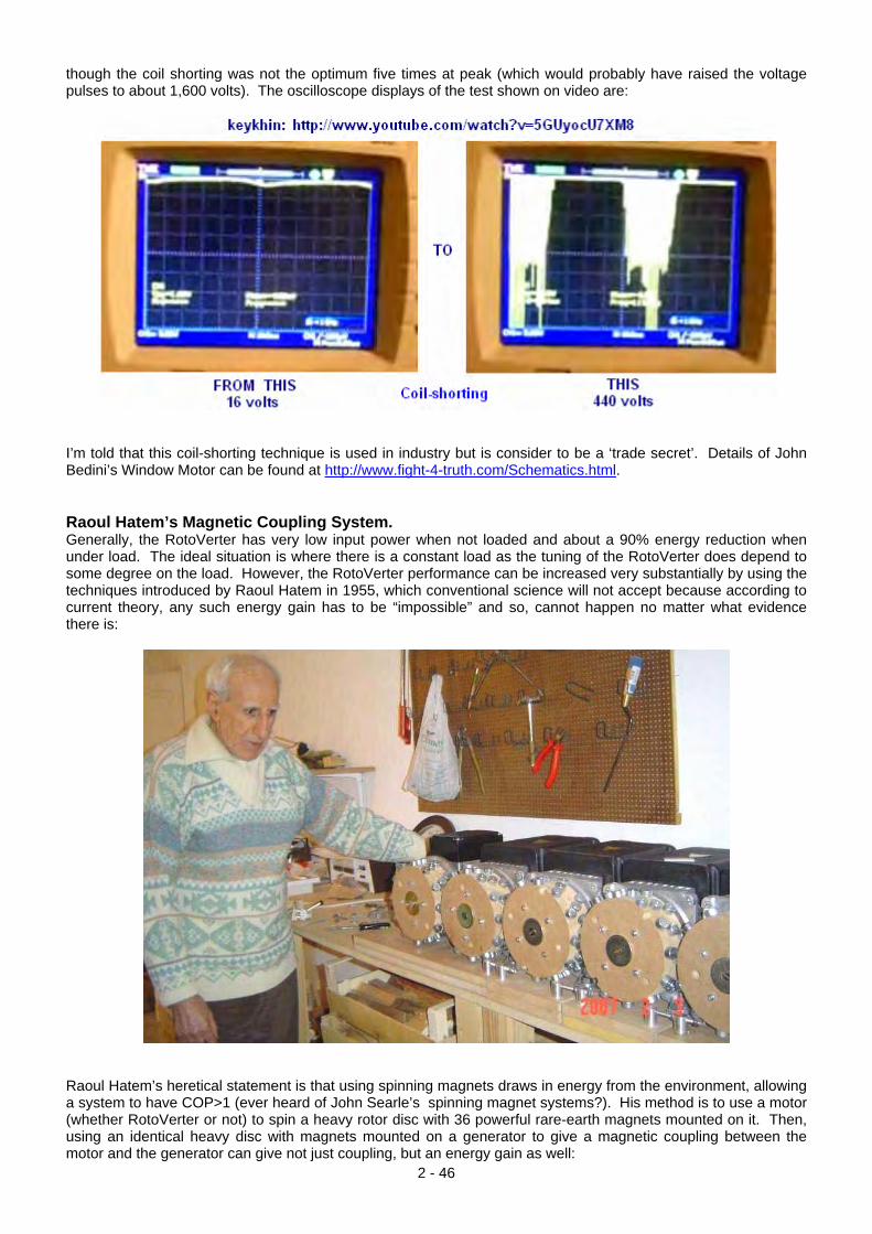
though the coil shorting was not the optimum five times at peak (which would probably have raised the voltage pulses to about 1,600 volts). The oscilloscope displays of the test shown on video are:
I’m told that this coil-shorting technique is used in industry but is consider to be a ‘trade secret’. Details of John Bedini’s Window Motor can be found at http://www.fight-4-truth.com/Schematics.html. Raoul Hatem’s Magnetic Coupling System. Generally, the RotoVerter has very low input power when not loaded and about a 90% energy reduction when under load. The ideal situation is where there is a constant load as the tuning of the RotoVerter does depend to some degree on the load. However, the RotoVerter performance can be increased very substantially by using the techniques introduced by Raoul Hatem in 1955, which conventional science will not accept because according to current theory, any such energy gain has to be “impossible” and so, cannot happen no matter what evidence there is:
Raoul Hatem’s heretical statement is that using spinning magnets draws in energy from the environment, allowing a system to have COP>1 (ever heard of John Searle’s spinning magnet systems?). His method is to use a motor (whether RotoVerter or not) to spin a heavy rotor disc with 36 powerful rare-earth magnets mounted on it. Then, using an identical heavy disc with magnets mounted on a generator to give a magnetic coupling between the motor and the generator can give not just coupling, but an energy gain as well:
2 - 46
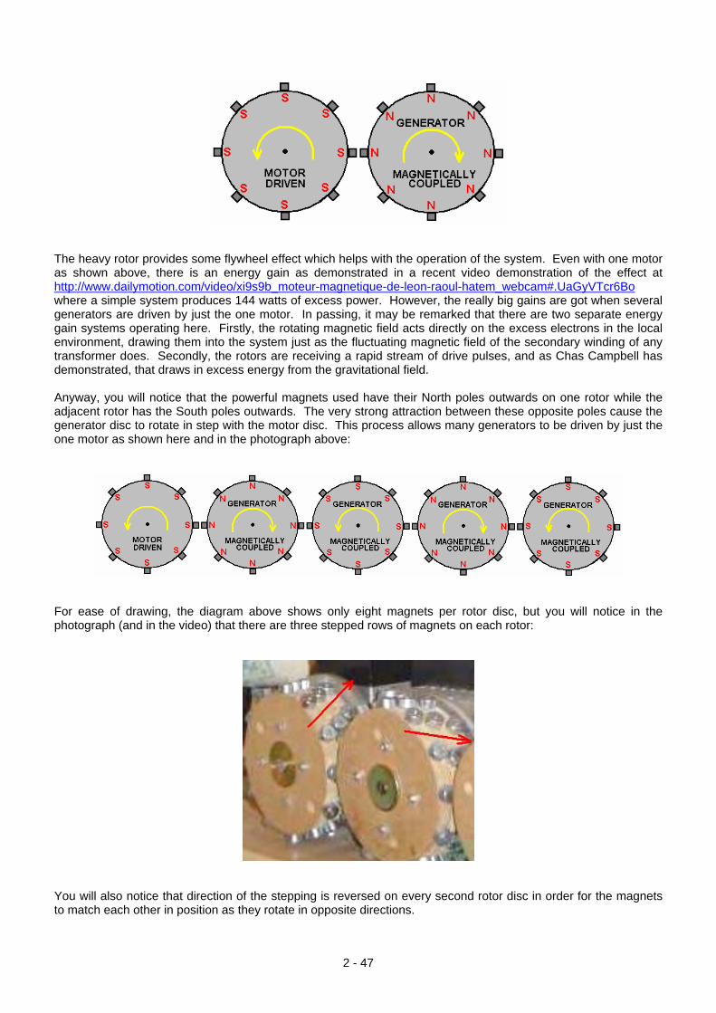
The heavy rotor provides some flywheel effect which helps with the operation of the system. Even with one motor as shown above, there is an energy gain as demonstrated in a recent video demonstration of the effect at http://www.dailymotion.com/video/xi9s9b_moteur-magnetique-de-leon-raoul-hatem_webcam#.UaGyVTcr6Bo where a simple system produces 144 watts of excess power. However, the really big gains are got when several generators are driven by just the one motor. In passing, it may be remarked that there are two separate energy gain systems operating here. Firstly, the rotating magnetic field acts directly on the excess electrons in the local environment, drawing them into the system just as the fluctuating magnetic field of the secondary winding of any transformer does. Secondly, the rotors are receiving a rapid stream of drive pulses, and as Chas Campbell has demonstrated, that draws in excess energy from the gravitational field. Anyway, you will notice that the powerful magnets used have their North poles outwards on one rotor while the adjacent rotor has the South poles outwards. The very strong attraction between these opposite poles cause the generator disc to rotate in step with the motor disc. This process allows many generators to be driven by just the one motor as shown here and in the photograph above:
For ease of drawing, the diagram above shows only eight magnets per rotor disc, but you will notice in the photograph (and in the video) that there are three stepped rows of magnets on each rotor:
You will also notice that direction of the stepping is reversed on every second rotor disc in order for the magnets to match each other in position as they rotate in opposite directions.
2 - 47
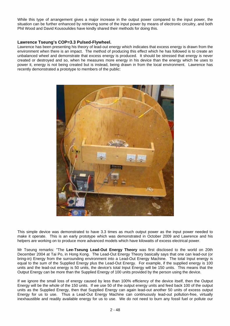
While this type of arrangement gives a major increase in the output power compared to the input power, the situation can be further enhanced by retrieving some of the input power by means of electronic circuitry, and both Phil Wood and David Kousoulides have kindly shared their methods for doing this. Lawrence Tseung’s COP=3.3 Pulsed-Flywheel. Lawrence has been presenting his theory of lead-out energy which indicates that excess energy is drawn from the environment when there is an impact. The method of producing this effect which he has followed is to create an unbalanced wheel and demonstrate that excess energy is produced. It should be stressed that energy is never created or destroyed and so, when he measures more energy in his device than the energy which he uses to power it, energy is not being created but is instead, being drawn in from the local environment. Lawrence has recently demonstrated a prototype to members of the public:
This simple device was demonstrated to have 3.3 times as much output power as the input power needed to make it operate. This is an early prototype which was demonstrated in October 2009 and Lawrence and his helpers are working on to produce more advanced models which have kilowatts of excess electrical power. Mr Tseung remarks: "The Lee-Tseung Lead-Out Energy Theory was first disclosed to the world on 20th December 2004 at Tai Po, in Hong Kong. The Lead-Out Energy Theory basically says that one can lead-out (or bring-in) Energy from the surrounding environment into a Lead-Out Energy Machine. The total Input energy is equal to the sum of the Supplied Energy plus the Lead-Out Energy. For example, if the supplied energy is 100 units and the lead-out energy is 50 units, the device's total Input Energy will be 150 units. This means that the Output Energy can be more than the Supplied Energy of 100 units provided by the person using the device. If we ignore the small loss of energy caused by less than 100% efficiency of the device itself, then the Output Energy will be the whole of the 150 units. If we use 50 of the output energy units and feed back 100 of the output units as the Supplied Energy, then that Supplied Energy can again lead-out another 50 units of excess output Energy for us to use. Thus a Lead-Out Energy Machine can continuously lead-out pollution-free, virtually inexhaustible and readily available energy for us to use. We do not need to burn any fossil fuel or pollute our
2 - 48
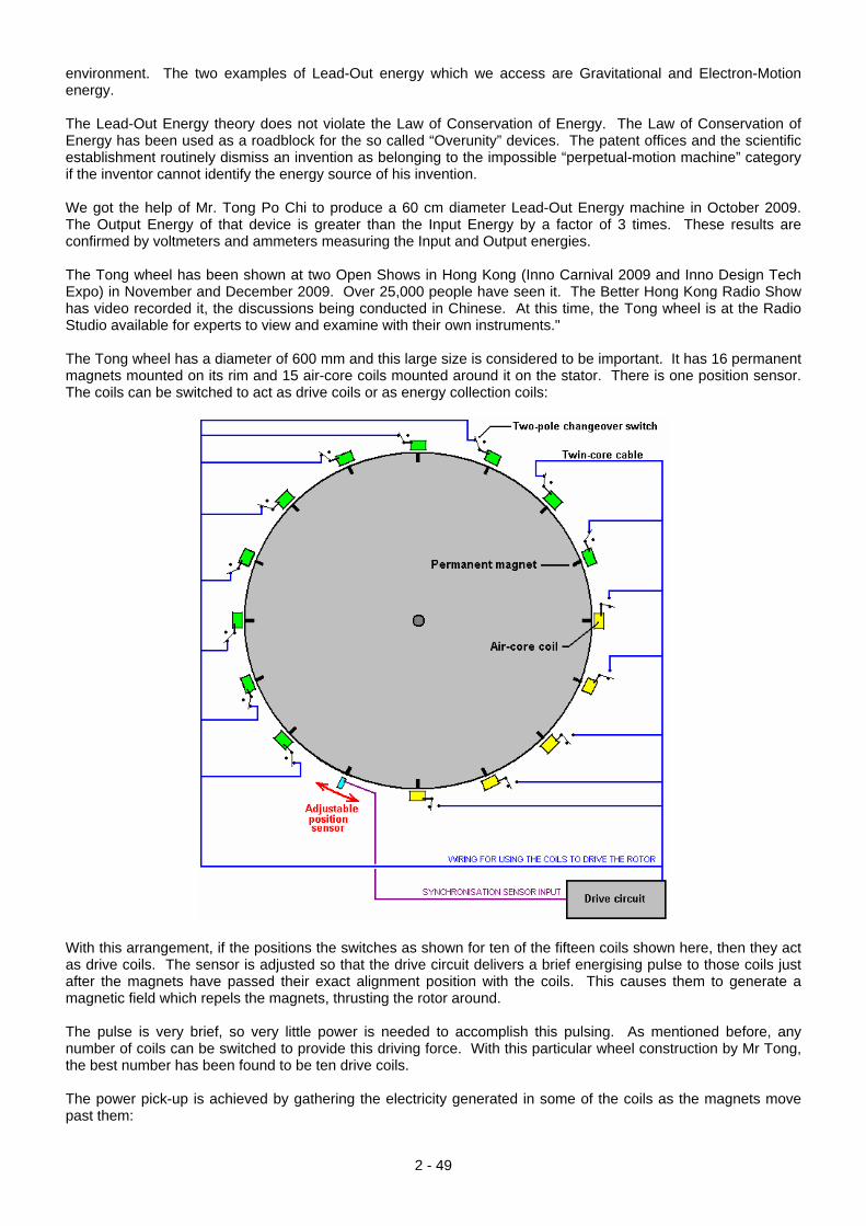
environment. The two examples of Lead-Out energy which we access are Gravitational and Electron-Motion energy. The Lead-Out Energy theory does not violate the Law of Conservation of Energy. The Law of Conservation of Energy has been used as a roadblock for the so called “Overunity” devices. The patent offices and the scientific establishment routinely dismiss an invention as belonging to the impossible “perpetual-motion machine” category if the inventor cannot identify the energy source of his invention. We got the help of Mr. Tong Po Chi to produce a 60 cm diameter Lead-Out Energy machine in October 2009. The Output Energy of that device is greater than the Input Energy by a factor of 3 times. These results are confirmed by voltmeters and ammeters measuring the Input and Output energies. The Tong wheel has been shown at two Open Shows in Hong Kong (Inno Carnival 2009 and Inno Design Tech Expo) in November and December 2009. Over 25,000 people have seen it. The Better Hong Kong Radio Show has video recorded it, the discussions being conducted in Chinese. At this time, the Tong wheel is at the Radio Studio available for experts to view and examine with their own instruments." The Tong wheel has a diameter of 600 mm and this large size is considered to be important. It has 16 permanent magnets mounted on its rim and 15 air-core coils mounted around it on the stator. There is one position sensor. The coils can be switched to act as drive coils or as energy collection coils:
With this arrangement, if the positions the switches as shown for ten of the fifteen coils shown here, then they act as drive coils. The sensor is adjusted so that the drive circuit delivers a brief energising pulse to those coils just after the magnets have passed their exact alignment position with the coils. This causes them to generate a magnetic field which repels the magnets, thrusting the rotor around. The pulse is very brief, so very little power is needed to accomplish this pulsing. As mentioned before, any number of coils can be switched to provide this driving force. With this particular wheel construction by Mr Tong, the best number has been found to be ten drive coils. The power pick-up is achieved by gathering the electricity generated in some of the coils as the magnets move past them:
2 - 49
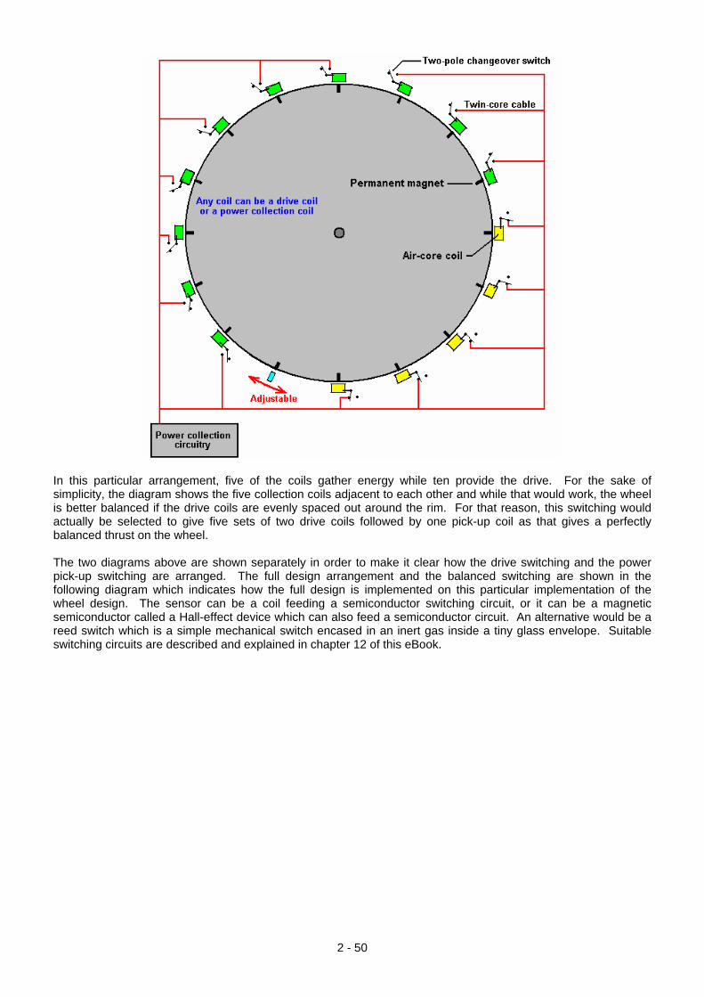
In this particular arrangement, five of the coils gather energy while ten provide the drive. For the sake of simplicity, the diagram shows the five collection coils adjacent to each other and while that would work, the wheel is better balanced if the drive coils are evenly spaced out around the rim. For that reason, this switching would actually be selected to give five sets of two drive coils followed by one pick-up coil as that gives a perfectly balanced thrust on the wheel. The two diagrams above are shown separately in order to make it clear how the drive switching and the power pick-up switching are arranged. The full design arrangement and the balanced switching are shown in the following diagram which indicates how the full design is implemented on this particular implementation of the wheel design. The sensor can be a coil feeding a semiconductor switching circuit, or it can be a magnetic semiconductor called a Hall-effect device which can also feed a semiconductor circuit. An alternative would be a reed switch which is a simple mechanical switch encased in an inert gas inside a tiny glass envelope. Suitable switching circuits are described and explained in chapter 12 of this eBook.
2 - 50
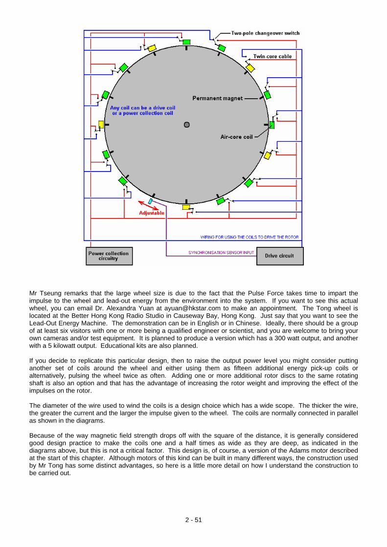
Mr Tseung remarks that the large wheel size is due to the fact that the Pulse Force takes time to impart the impulse to the wheel and lead-out energy from the environment into the system. If you want to see this actual wheel, you can email Dr. Alexandra Yuan at [email protected] to make an appointment. The Tong wheel is located at the Better Hong Kong Radio Studio in Causeway Bay, Hong Kong. Just say that you want to see the Lead-Out Energy Machine. The demonstration can be in English or in Chinese. Ideally, there should be a group of at least six visitors with one or more being a qualified engineer or scientist, and you are welcome to bring your own cameras and/or test equipment. It is planned to produce a version which has a 300 watt output, and another with a 5 kilowatt output. Educational kits are also planned. If you decide to replicate this particular design, then to raise the output power level you might consider putting another set of coils around the wheel and either using them as fifteen additional energy pick-up coils or alternatively, pulsing the wheel twice as often. Adding one or more additional rotor discs to the same rotating shaft is also an option and that has the advantage of increasing the rotor weight and improving the effect of the impulses on the rotor. The diameter of the wire used to wind the coils is a design choice which has a wide scope. The thicker the wire, the greater the current and the larger the impulse given to the wheel. The coils are normally connected in parallel as shown in the diagrams. Because of the way magnetic field strength drops off with the square of the distance, it is generally considered good design practice to make the coils one and a half times as wide as they are deep, as indicated in the diagrams above, but this is not a critical factor. This design is, of course, a version of the Adams motor described at the start of this chapter. Although motors of this kind can be built in many different ways, the construction used by Mr Tong has some distinct advantages, so here is a little more detail on how I understand the construction to be carried out.
2 - 51
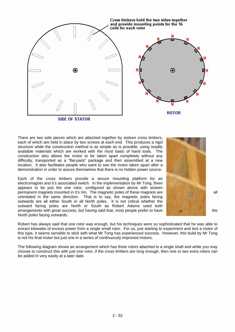
There are two side pieces which are attached together by sixteen cross timbers, each of which are held in place by two screws at each end. This produces a rigid structure while the construction method is as simple as is possible, using readily available materials which are worked with the most basic of hand tools. The construction also allows the motor to be taken apart completely without any difficulty, transported as a “flat-pack” package and then assembled at a new location. It also facilitates people who want to see the motor taken apart after a demonstration in order to assure themselves that there is no hidden power source. Each of the cross timbers provide a secure mounting platform for an electromagnet and it’s associated switch. In the implementation by Mr Tong, there appears to be just the one rotor, configured as shown above with sixteen permanent magnets mounted in it’s rim. The magnetic poles of these magnets are all orientated in the same direction. That is to say, the magnetic poles facing outwards are all either South or all North poles. It is not critical whether the outward facing poles are North or South as Robert Adams used both arrangements with great success, but having said that, most people prefer to have the North poles facing outwards. Robert has always said that one rotor was enough, but his techniques were so sophisticated that he was able to extract kilowatts of excess power from a single small rotor. For us, just starting to experiment and test a motor of this type, it seems sensible to stick with what Mr Tong has experienced success. However, this build by Mr Tong is not his final motor but just one in a series of continuously improved motors. The following diagram shows an arrangement which has three rotors attached to a single shaft and while you may choose to construct this with just one rotor, if the cross timbers are long enough, then one or two extra rotors can be added in very easily at a later date.
2 - 52
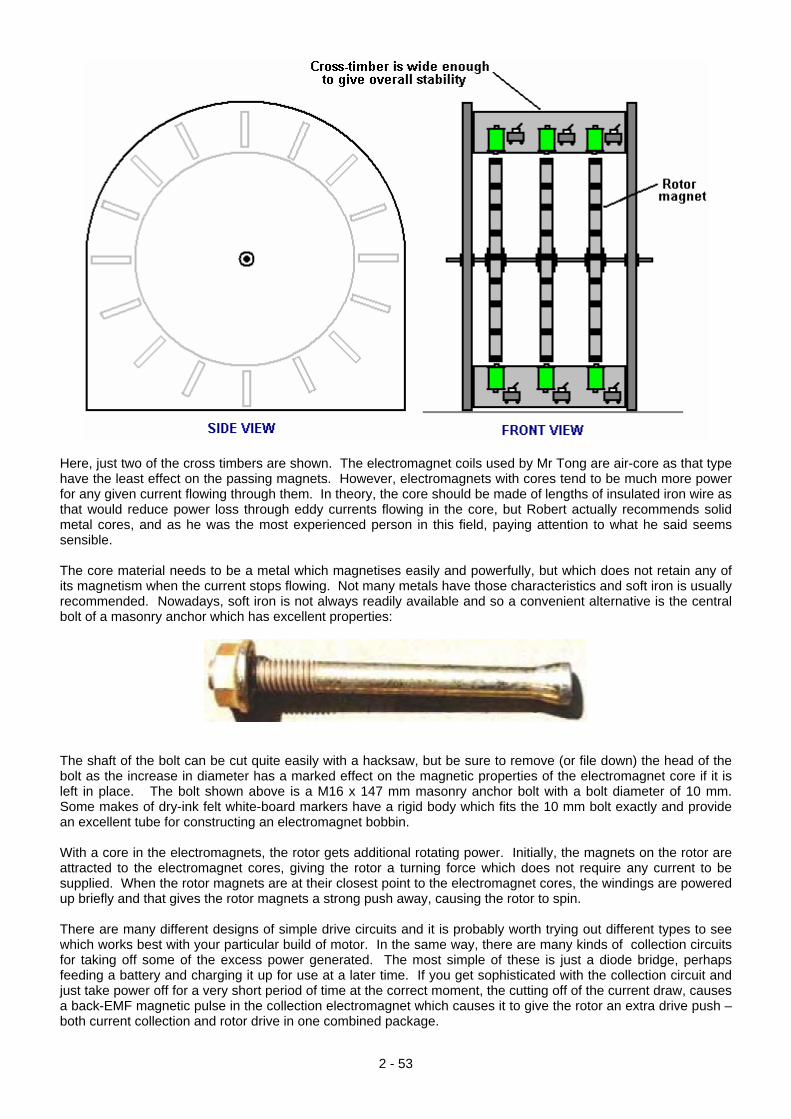
Here, just two of the cross timbers are shown. The electromagnet coils used by Mr Tong are air-core as that type have the least effect on the passing magnets. However, electromagnets with cores tend to be much more power for any given current flowing through them. In theory, the core should be made of lengths of insulated iron wire as that would reduce power loss through eddy currents flowing in the core, but Robert actually recommends solid metal cores, and as he was the most experienced person in this field, paying attention to what he said seems sensible. The core material needs to be a metal which magnetises easily and powerfully, but which does not retain any of its magnetism when the current stops flowing. Not many metals have those characteristics and soft iron is usually recommended. Nowadays, soft iron is not always readily available and so a convenient alternative is the central bolt of a masonry anchor which has excellent properties:
The shaft of the bolt can be cut quite easily with a hacksaw, but be sure to remove (or file down) the head of the bolt as the increase in diameter has a marked effect on the magnetic properties of the electromagnet core if it is left in place. The bolt shown above is a M16 x 147 mm masonry anchor bolt with a bolt diameter of 10 mm. Some makes of dry-ink felt white-board markers have a rigid body which fits the 10 mm bolt exactly and provide an excellent tube for constructing an electromagnet bobbin. With a core in the electromagnets, the rotor gets additional rotating power. Initially, the magnets on the rotor are attracted to the electromagnet cores, giving the rotor a turning force which does not require any current to be supplied. When the rotor magnets are at their closest point to the electromagnet cores, the windings are powered up briefly and that gives the rotor magnets a strong push away, causing the rotor to spin. There are many different designs of simple drive circuits and it is probably worth trying out different types to see which works best with your particular build of motor. In the same way, there are many kinds of collection circuits for taking off some of the excess power generated. The most simple of these is just a diode bridge, perhaps feeding a battery and charging it up for use at a later time. If you get sophisticated with the collection circuit and just take power off for a very short period of time at the correct moment, the cutting off of the current draw, causes a back-EMF magnetic pulse in the collection electromagnet which causes it to give the rotor an extra drive push – both current collection and rotor drive in one combined package.
2 - 53
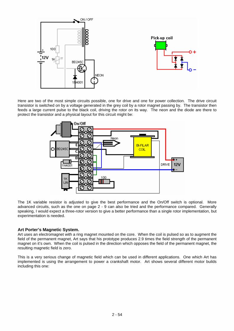
Here are two of the most simple circuits possible, one for drive and one for power collection. The drive circuit transistor is switched on by a voltage generated in the grey coil by a rotor magnet passing by. The transistor then feeds a large current pulse to the black coil, driving the rotor on its way. The neon and the diode are there to protect the transistor and a physical layout for this circuit might be:
The 1K variable resistor is adjusted to give the best performance and the On/Off switch is optional. More advanced circuits, such as the one on page 2 - 9 can also be tried and the performance compared. Generally speaking, I would expect a three-rotor version to give a better performance than a single rotor implementation, but experimentation is needed. Art Porter’s Magnetic System. Art uses an electromagnet with a ring magnet mounted on the core. When the coil is pulsed so as to augment the field of the permanent magnet, Art says that his prototype produces 2.9 times the field strength of the permanent magnet on it’s own. When the coil is pulsed in the direction which opposes the field of the permanent magnet, the resulting magnetic field is zero. This is a very serious change of magnetic field which can be used in different applications. One which Art has implemented is using the arrangement to power a crankshaft motor. Art shows several different motor builds including this one:
2 - 54
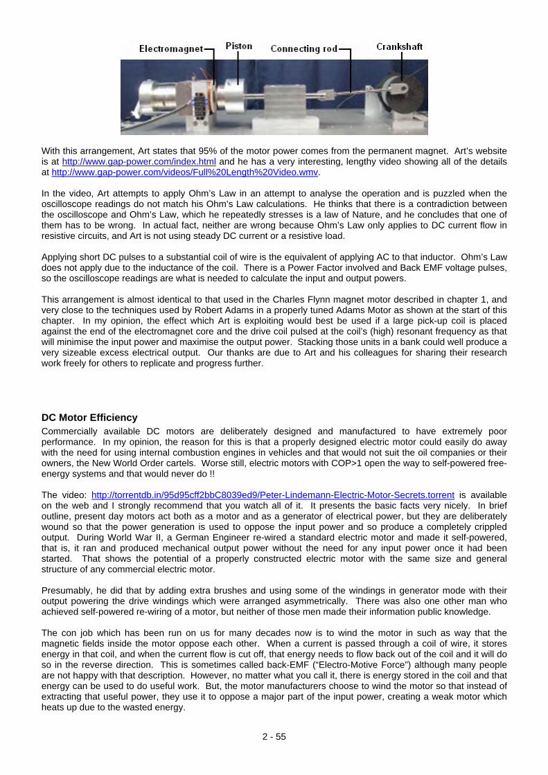
With this arrangement, Art states that 95% of the motor power comes from the permanent magnet. Art’s website is at http://www.gap-power.com/index.html and he has a very interesting, lengthy video showing all of the details at http://www.gap-power.com/videos/Full%20Length%20Video.wmv. In the video, Art attempts to apply Ohm’s Law in an attempt to analyse the operation and is puzzled when the oscilloscope readings do not match his Ohm’s Law calculations. He thinks that there is a contradiction between the oscilloscope and Ohm’s Law, which he repeatedly stresses is a law of Nature, and he concludes that one of them has to be wrong. In actual fact, neither are wrong because Ohm’s Law only applies to DC current flow in resistive circuits, and Art is not using steady DC current or a resistive load. Applying short DC pulses to a substantial coil of wire is the equivalent of applying AC to that inductor. Ohm’s Law does not apply due to the inductance of the coil. There is a Power Factor involved and Back EMF voltage pulses, so the oscilloscope readings are what is needed to calculate the input and output powers. This arrangement is almost identical to that used in the Charles Flynn magnet motor described in chapter 1, and very close to the techniques used by Robert Adams in a properly tuned Adams Motor as shown at the start of this chapter. In my opinion, the effect which Art is exploiting would best be used if a large pick-up coil is placed against the end of the electromagnet core and the drive coil pulsed at the coil’s (high) resonant frequency as that will minimise the input power and maximise the output power. Stacking those units in a bank could well produce a very sizeable excess electrical output. Our thanks are due to Art and his colleagues for sharing their research work freely for others to replicate and progress further.
DC Motor Efficiency Commercially available DC motors are deliberately designed and manufactured to have extremely poor performance. In my opinion, the reason for this is that a properly designed electric motor could easily do away with the need for using internal combustion engines in vehicles and that would not suit the oil companies or their owners, the New World Order cartels. Worse still, electric motors with COP>1 open the way to self-powered free-energy systems and that would never do !! The video: http://torrentdb.in/95d95cff2bbC8039ed9/Peter-Lindemann-Electric-Motor-Secrets.torrent is available on the web and I strongly recommend that you watch all of it. It presents the basic facts very nicely. In brief outline, present day motors act both as a motor and as a generator of electrical power, but they are deliberately wound so that the power generation is used to oppose the input power and so produce a completely crippled output. During World War II, a German Engineer re-wired a standard electric motor and made it self-powered, that is, it ran and produced mechanical output power without the need for any input power once it had been started. That shows the potential of a properly constructed electric motor with the same size and general structure of any commercial electric motor. Presumably, he did that by adding extra brushes and using some of the windings in generator mode with their output powering the drive windings which were arranged asymmetrically. There was also one other man who achieved self-powered re-wiring of a motor, but neither of those men made their information public knowledge. The con job which has been run on us for many decades now is to wind the motor in such as way that the magnetic fields inside the motor oppose each other. When a current is passed through a coil of wire, it stores energy in that coil, and when the current flow is cut off, that energy needs to flow back out of the coil and it will do so in the reverse direction. This is sometimes called back-EMF (“Electro-Motive Force”) although many people are not happy with that description. However, no matter what you call it, there is energy stored in the coil and that energy can be used to do useful work. But, the motor manufacturers choose to wind the motor so that instead of extracting that useful power, they use it to oppose a major part of the input power, creating a weak motor which heats up due to the wasted energy.
2 - 55
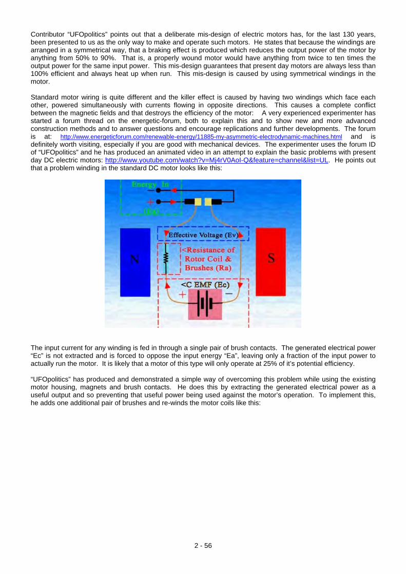
Contributor “UFOpolitics” points out that a deliberate mis-design of electric motors has, for the last 130 years, been presented to us as the only way to make and operate such motors. He states that because the windings are arranged in a symmetrical way, that a braking effect is produced which reduces the output power of the motor by anything from 50% to 90%. That is, a properly wound motor would have anything from twice to ten times the output power for the same input power. This mis-design guarantees that present day motors are always less than 100% efficient and always heat up when run. This mis-design is caused by using symmetrical windings in the motor. Standard motor wiring is quite different and the killer effect is caused by having two windings which face each other, powered simultaneously with currents flowing in opposite directions. This causes a complete conflict between the magnetic fields and that destroys the efficiency of the motor: A very experienced experimenter has started a forum thread on the energetic-forum, both to explain this and to show new and more advanced construction methods and to answer questions and encourage replications and further developments. The forum is at: http://www.energeticforum.com/renewable-energy/11885-my-asymmetric-electrodynamic-machines.html and is definitely worth visiting, especially if you are good with mechanical devices. The experimenter uses the forum ID of “UFOpolitics” and he has produced an animated video in an attempt to explain the basic problems with present day DC electric motors: http://www.youtube.com/watch?v=Mj4rV0AoI-Q&feature=channel&list=UL. He points out that a problem winding in the standard DC motor looks like this:
The input current for any winding is fed in through a single pair of brush contacts. The generated electrical power “Ec” is not extracted and is forced to oppose the input energy “Ea”, leaving only a fraction of the input power to actually run the motor. It is likely that a motor of this type will only operate at 25% of it’s potential efficiency. “UFOpolitics” has produced and demonstrated a simple way of overcoming this problem while using the existing motor housing, magnets and brush contacts. He does this by extracting the generated electrical power as a useful output and so preventing that useful power being used against the motor’s operation. To implement this, he adds one additional pair of brushes and re-winds the motor coils like this:
2 - 56
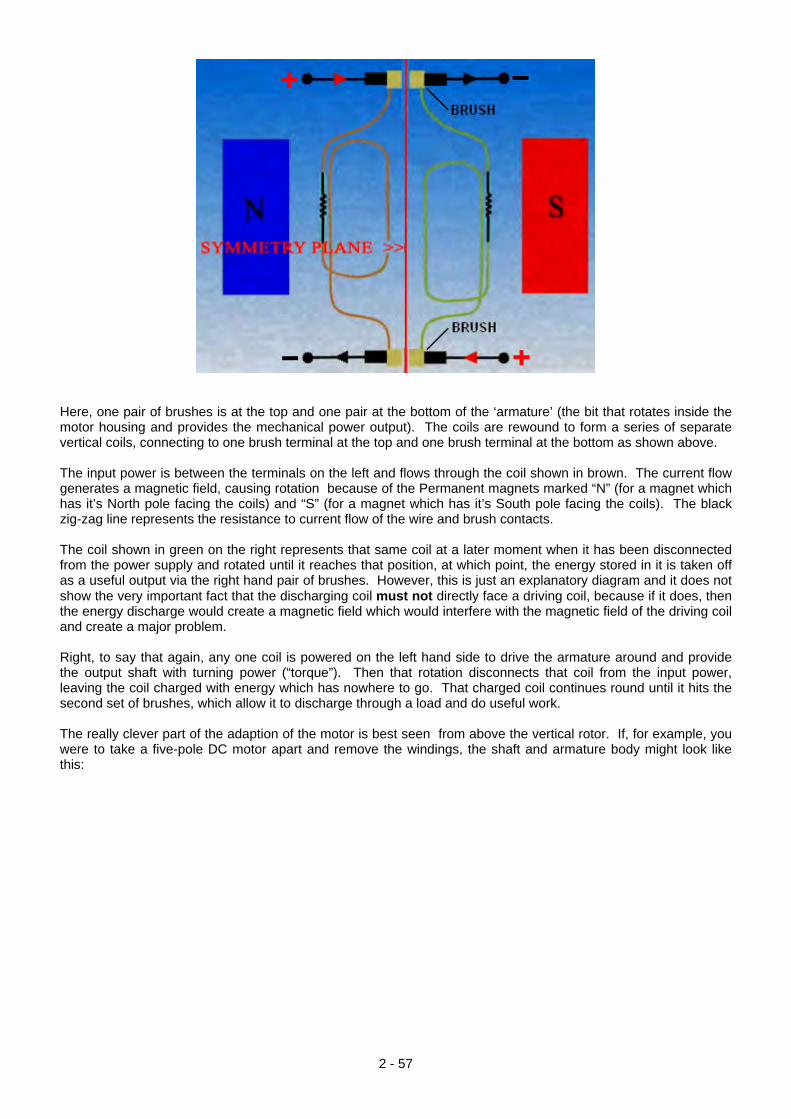
Here, one pair of brushes is at the top and one pair at the bottom of the ‘armature’ (the bit that rotates inside the motor housing and provides the mechanical power output). The coils are rewound to form a series of separate vertical coils, connecting to one brush terminal at the top and one brush terminal at the bottom as shown above. The input power is between the terminals on the left and flows through the coil shown in brown. The current flow generates a magnetic field, causing rotation because of the Permanent magnets marked “N” (for a magnet which has it’s North pole facing the coils) and “S” (for a magnet which has it’s South pole facing the coils). The black zig-zag line represents the resistance to current flow of the wire and brush contacts. The coil shown in green on the right represents that same coil at a later moment when it has been disconnected from the power supply and rotated until it reaches that position, at which point, the energy stored in it is taken off as a useful output via the right hand pair of brushes. However, this is just an explanatory diagram and it does not show the very important fact that the discharging coil must not directly face a driving coil, because if it does, then the energy discharge would create a magnetic field which would interfere with the magnetic field of the driving coil and create a major problem. Right, to say that again, any one coil is powered on the left hand side to drive the armature around and provide the output shaft with turning power (“torque”). Then that rotation disconnects that coil from the input power, leaving the coil charged with energy which has nowhere to go. That charged coil continues round until it hits the second set of brushes, which allow it to discharge through a load and do useful work. The really clever part of the adaption of the motor is best seen from above the vertical rotor. If, for example, you were to take a five-pole DC motor apart and remove the windings, the shaft and armature body might look like this:
2 - 57
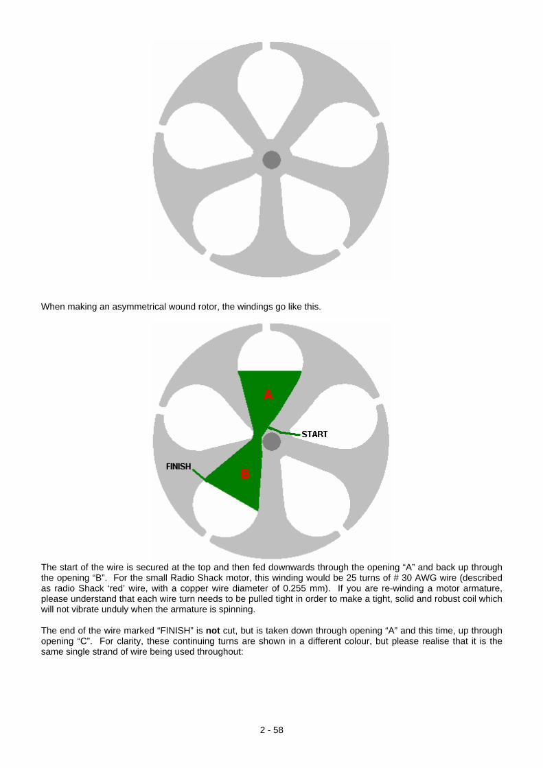
When making an asymmetrical wound rotor, the windings go like this.
The start of the wire is secured at the top and then fed downwards through the opening “A” and back up through the opening “B”. For the small Radio Shack motor, this winding would be 25 turns of # 30 AWG wire (described as radio Shack ‘red’ wire, with a copper wire diameter of 0.255 mm). If you are re-winding a motor armature, please understand that each wire turn needs to be pulled tight in order to make a tight, solid and robust coil which will not vibrate unduly when the armature is spinning. The end of the wire marked “FINISH” is not cut, but is taken down through opening “A” and this time, up through opening “C”. For clarity, these continuing turns are shown in a different colour, but please realise that it is the same single strand of wire being used throughout:
2 - 58
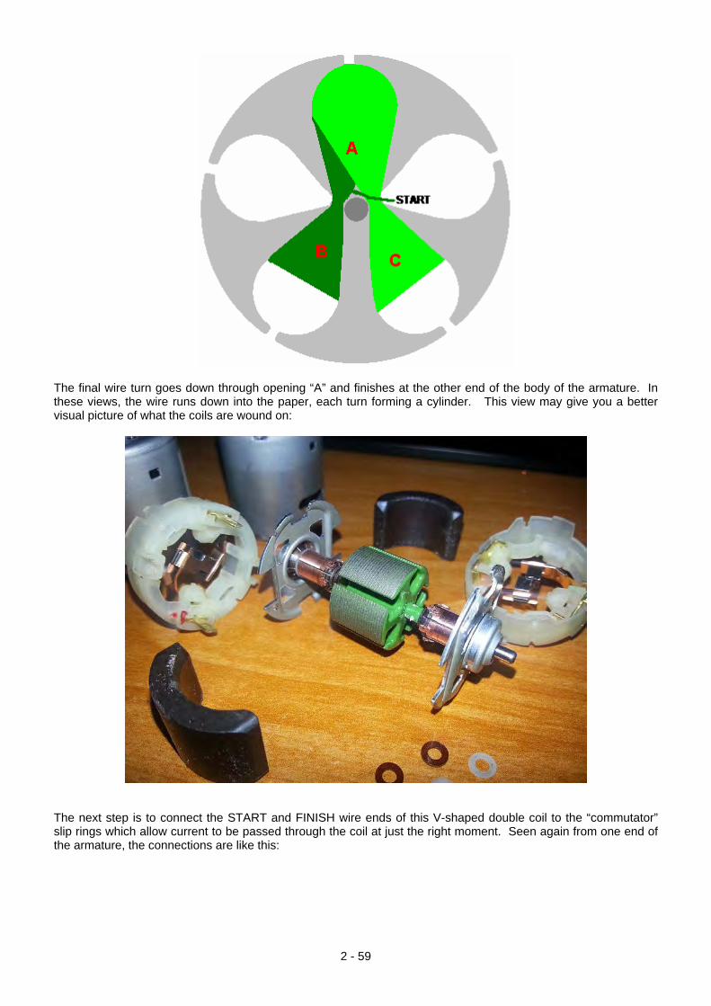
The final wire turn goes down through opening “A” and finishes at the other end of the body of the armature. In these views, the wire runs down into the paper, each turn forming a cylinder. This view may give you a better visual picture of what the coils are wound on:
The next step is to connect the START and FINISH wire ends of this V-shaped double coil to the “commutator” slip rings which allow current to be passed through the coil at just the right moment. Seen again from one end of the armature, the connections are like this:
2 - 59
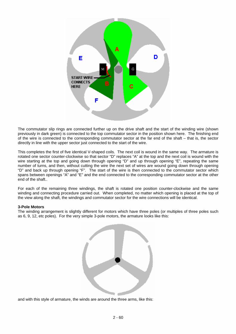
The commutator slip rings are connected further up on the drive shaft and the start of the winding wire (shown previously in dark green) is connected to the top commutator sector in the position shown here. The finishing end of the wire is connected to the corresponding commutator sector at the far end of the shaft – that is, the sector directly in line with the upper sector just connected to the start of the wire. This completes the first of five identical V-shaped coils. The next coil is wound in the same way. The armature is rotated one sector counter-clockwise so that sector “D” replaces “A” at the top and the next coil is wound with the wire starting at the top and going down through opening “D” and up through opening “E”, repeating the same number of turns, and then, without cutting the wire the next set of wires are wound going down through opening “D” and back up through opening “F”. The start of the wire is then connected to the commutator sector which spans between openings “A” and “E” and the end connected to the corresponding commutator sector at the other end of the shaft.. For each of the remaining three windings, the shaft is rotated one position counter-clockwise and the same winding and connecting procedure carried out. When completed, no matter which opening is placed at the top of the view along the shaft, the windings and commutator sector for the wire connections will be identical. 3-Pole Motors The winding arrangement is slightly different for motors which have three poles (or multiples of three poles such as 6, 9, 12, etc poles). For the very simple 3-pole motors, the armature looks like this:
and with this style of armature, the winds are around the three arms, like this:
2 - 60
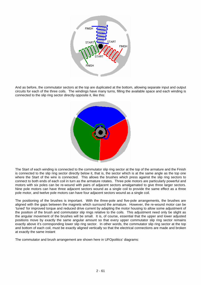
And as before, the commutator sectors at the top are duplicated at the bottom, allowing separate input and output circuits for each of the three coils. The windings have many turns, filling the available space and each winding is connected to the slip ring sector directly opposite it, like this:
The Start of each winding is connected to the commutator slip ring sector at the top of the armature and the Finish is connected to the slip ring sector directly below it, that is, the sector which is at the same angle as the top one where the Start of the wire is connected. This allows the brushes which press against the slip ring sectors to connect to both ends of each coil in turn as the armature rotates. Three pole motors are particularly powerful and motors with six poles can be re-wound with pairs of adjacent sectors amalgamated to give three larger sectors. Nine pole motors can have three adjacent sectors wound as a single coil to provide the same effect as a three pole motor, and twelve pole motors can have four adjacent sectors wound as a single coil. The positioning of the brushes is important. With the three-pole and five-pole arrangements, the brushes are aligned with the gaps between the magnets which surround the armature. However, the re-wound motor can be ‘tuned’ for improved torque and reduced drive current by adapting the motor housing to allow some adjustment of the position of the brush and commutator slip rings relative to the coils. This adjustment need only be slight as the angular movement of the brushes will be small. It is, of course, essential that the upper and lower adjusted positions move by exactly the same angular amount so that every upper commutator slip ring sector remains exactly above it’s corresponding lower slip ring sector. In other words, the commutator slip ring sector at the top and bottom of each coil, must be exactly aligned vertically so that the electrical connections are made and broken at exactly the same instant The commutator and brush arrangement are shown here in UFOpolitics’ diagrams:
2 - 61
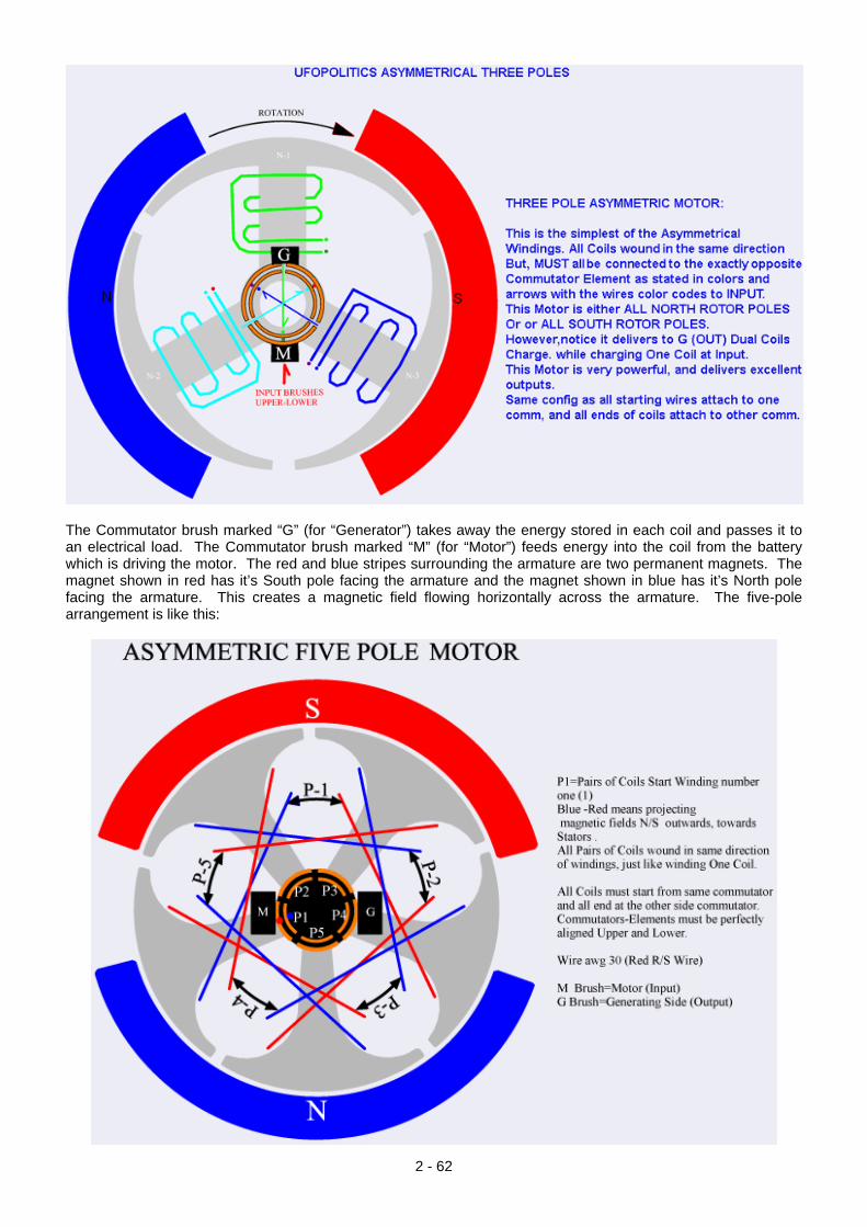
The Commutator brush marked “G” (for “Generator”) takes away the energy stored in each coil and passes it to an electrical load. The Commutator brush marked “M” (for “Motor”) feeds energy into the coil from the battery which is driving the motor. The red and blue stripes surrounding the armature are two permanent magnets. The magnet shown in red has it’s South pole facing the armature and the magnet shown in blue has it’s North pole facing the armature. This creates a magnetic field flowing horizontally across the armature. The five-pole arrangement is like this:
2 - 62
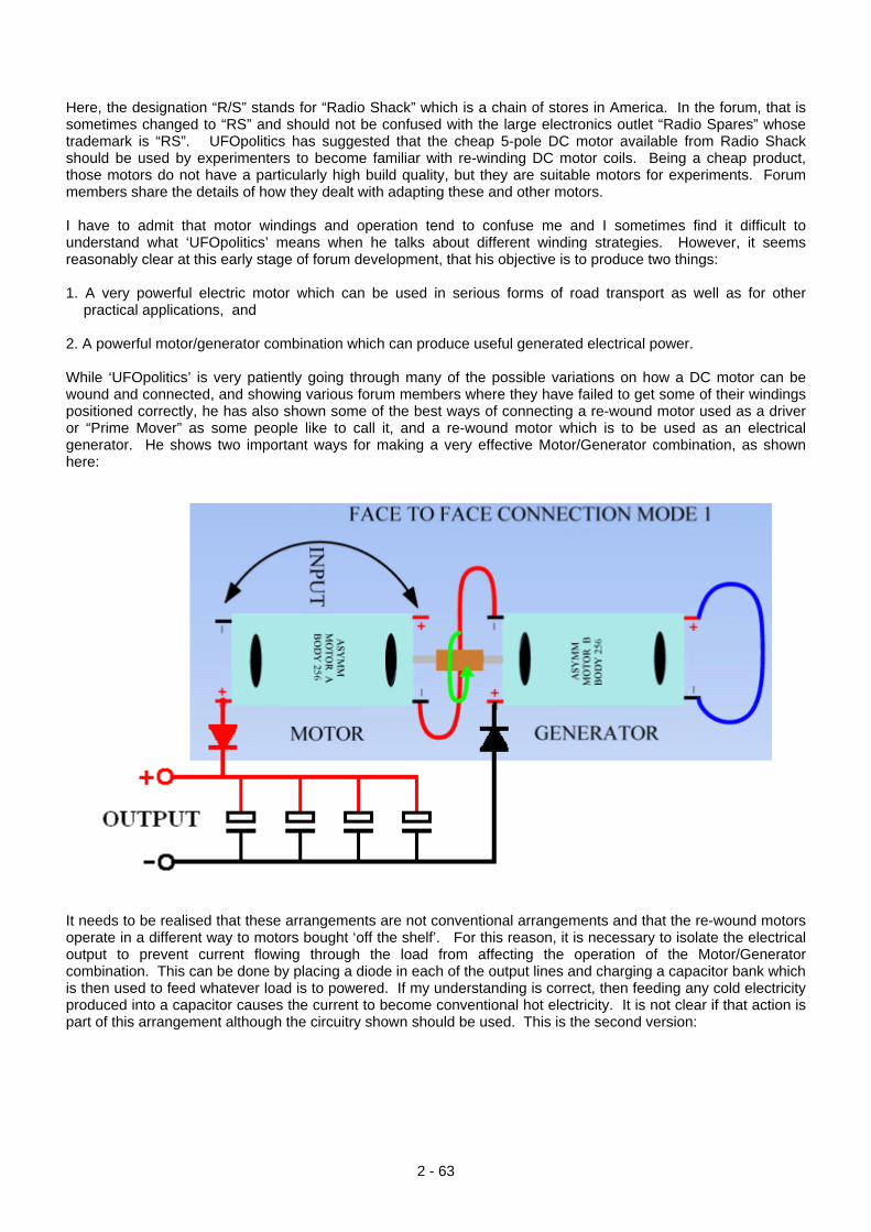
Here, the designation “R/S” stands for “Radio Shack” which is a chain of stores in America. In the forum, that is sometimes changed to “RS” and should not be confused with the large electronics outlet “Radio Spares” whose trademark is “RS”. UFOpolitics has suggested that the cheap 5-pole DC motor available from Radio Shack should be used by experimenters to become familiar with re-winding DC motor coils. Being a cheap product, those motors do not have a particularly high build quality, but they are suitable motors for experiments. Forum members share the details of how they dealt with adapting these and other motors. I have to admit that motor windings and operation tend to confuse me and I sometimes find it difficult to understand what ‘UFOpolitics’ means when he talks about different winding strategies. However, it seems reasonably clear at this early stage of forum development, that his objective is to produce two things: 1. A very powerful electric motor which can be used in serious forms of road transport as well as for other
practical applications, and 2. A powerful motor/generator combination which can produce useful generated electrical power. While ‘UFOpolitics’ is very patiently going through many of the possible variations on how a DC motor can be wound and connected, and showing various forum members where they have failed to get some of their windings positioned correctly, he has also shown some of the best ways of connecting a re-wound motor used as a driver or “Prime Mover” as some people like to call it, and a re-wound motor which is to be used as an electrical generator. He shows two important ways for making a very effective Motor/Generator combination, as shown here:
It needs to be realised that these arrangements are not conventional arrangements and that the re-wound motors operate in a different way to motors bought ‘off the shelf’. For this reason, it is necessary to isolate the electrical output to prevent current flowing through the load from affecting the operation of the Motor/Generator combination. This can be done by placing a diode in each of the output lines and charging a capacitor bank which is then used to feed whatever load is to powered. If my understanding is correct, then feeding any cold electricity produced into a capacitor causes the current to become conventional hot electricity. It is not clear if that action is part of this arrangement although the circuitry shown should be used. This is the second version:
2 - 63
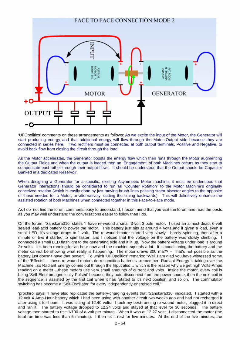
‘UFOpolitics’ comments on these arrangements as follows: As we excite the input of the Motor, the Generator will start producing energy and that additional energy will flow through the Motor Output side because they are connected in series here. Two rectifiers must be connected at both output terminals, Positive and Negative, to avoid back flow from closing the circuit through the load. As the Motor accelerates, the Generator boosts the energy flow which then runs through the Motor augmenting the Output Fields and when the output is loaded then an ‘Engagement’ of both Machines occurs as they start to compensate each other through their output flows. It should be understood that the Output should be Capacitor Banked in a dedicated Reservoir. When designing a Generator for a specific, existing Asymmetric Motor machine, it must be understood that Generator Interactions should be considered to run as “Counter Rotation” to the Motor Machine’s originally conceived rotation (which is easily done by just moving brush-lines passing stator bisector angles to the opposite of those needed for a Motor, or alternatively, setting the timing backwards). This will definitively enhance the assisted rotation of both Machines when connected together in this Face-to-Face mode. As I do not find the forum comments easy to understand, I recommend that you visit the forum and read the posts as you may well understand the conversations easier to follow than I do. On the forum, ‘Sanskara316’ states “I have re-wound a small 3-volt 3-pole motor. I used an almost dead, 6-volt sealed lead-acid battery to power the motor. This battery just sits at around 4 volts and if given a load, even a small LED, it’s voltage drops to 1 volt. The re-wound motor started very slowly - barely spinning, then after a minute or two it started to spin faster, and I noticed that the voltage on the battery was slowly climbing. I connected a small LED flashlight to the generating side and it lit up. Now the battery voltage under load is around 2+ volts. It’s been running for an hour now and the machine squeals a lot. It is conditioning the battery and the meter cannot be showing what really is happening. The motor draws 300 ma?? – That’s not possible as the battery just doesn't have that power”. To which ‘UFOpolitics’ remarks: “Well I am glad you have witnessed some of the ‘Effects’... these re-wound motors do recondition batteries...remember, Radiant Energy is taking over the Machine...so Radiant Energy comes out through the Input also… which is the reason why we get high Volts-Amps reading on a meter ...these motors use very small amounts of current and volts. Inside the motor, every coil is being ‘Self-Electromagnetically-Pulsed’ because they auto-disconnect from the power source, then the next coil in the sequence is assisted by the first coil when it has rotated to it’s next position, and so on. The commutator switching has become a ‘Self-Oscillator’ for every independently-energised coil.” ‘prochiro’ says: “I have also replicated the battery-charging events that ‘Sanskara316’ indicated. I started with a 12-volt 4 Amp-Hour battery which I had been using with another circuit two weeks ago and had not recharged it after using it for hours. It was sitting at 12.40 volts. I took my best-running re-wound motor, plugged it in direct and ran it. The battery voltage dropped to 12.24 volts and stayed at that level for 30 seconds. The battery voltage then started to rise 1/100 of a volt per minute. When it was at 12.27 volts, I disconnected the motor (the total run time was less than 5 minutes). I then let it rest for five minutes. At the end of the five minutes, the
2 - 64

2 - 65
battery voltage had risen to 12.43 volts and is still at that voltage now. Just think what a larger motor would do on a big battery bank. Everybody needs to document this test as it proves what ‘UFOpolitics’ said.” New DC motors, and particularly cheap motors, will have brushes which do not mate cleanly with the commutator slip ring sectors and so, when the modification has been made, running the motor for some time allows the brushes to wear in and that raises the efficiency of the electrical connections which in turn, improves the performance of the motor. If you wish to build and test one of these motors, then you can find help and support in the forum with your questions answered and numerous videos and photographs from different experimenters to help you. Patrick Kelly http://www.free-energy-info.tuks.nl/
![Cross sectional study.pptx [Read-Only]...Descriptive cross-sectional study Analytic cross-sectional study Repeated cross-sectional study 7 Descriptive Collected number of cases and](https://img.pdfslide.us/doc/110x75/5f0c07f77e708231d43368fd/cross-sectional-studypptx-read-only-descriptive-cross-sectional-study-analytic.jpg)