Embed Size (px)
Citation preview

Chapter 2:
Fundamentals of Data and Signals

2
Objectives
After reading this chapter, you should be able to:
•Distinguish between data and signals, and cite the advantages of digital data and signal over analog data and signals
•Identify the three basic components of a signal
•Discuss the bandwidth of a signal and how it relates to data transfer speed
3
Objectives (continued)
•Identify signal strength and attenuation, and how they are related
•Outline the basic characteristics of transmitting analog data with analog signals, digital data with digital signals, digital data with analog signals, and analog data with digital signals
•List and draw diagrams of the basic digital encoding techniques, and explain the advantages and disadvantages of each

4
Objectives (continued)
•Identify the different shift keying (modulation) techniques and describe their advantages, disadvantages, and uses
•Identify the two most common digitization techniques and describe their advantages and disadvantages
•Discuss the characteristics and importance of spread spectrum encoding techniques
•Identify the different data codes and how they are used in communication systems

5
Introduction – Data and Signals
•Data - entities that convey meaning
•Examples: computer file, music on a CD, results from a blood gas analysis machine
•Signals - electric or electromagnetic encoding of data
•Examples: telephone conversation, web page download
•Computer networks and data / voice communication systems transmit signals
•Data and signals can be analog or digital

6
Introduction – Data and Signals (continued)

7
Analog versus Digital
•Analog - continuous waveform
•Examples: (naturally occurring) music and voice

8
Analog versus Digital (continued)
•Harder to separate noise from an analog signal than from a digital signal

9
Analog versus Digital (continued)
•Digital - discrete or non-continuous waveform
•Examples: computer 1s and 0s

10
Analog versus Digital (continued)
•Despite noise in this digital signal
•You can still discern a high voltage from a low voltage

11
Analog versus Digital (continued)
•If there is too much noise
• You cannot discern a high voltage from a low voltage

12
Fundamentals of Signals
•All Signals Have Three Components
•Amplitude
•Frequency
•Phase

13
Fundamentals of Signals (continued)
Amplitude
•Height of the wave above or below a given reference point

14
Fundamentals of Signals (continued)
Frequency
•Number of times a signal makes complete cycle within a given time frame
Spectrum - Range of frequencies that a signal spans from minimum to maximum
Bandwidth - The absolute value of the difference between the lowest and highest frequencies of a signal

15
Fundamentals of Signals (continued)

16
Fundamentals of Signals (continued)
Frequency (continued)
•For example, consider an average voice:
•Average voice has a frequency range of roughly 300 Hz to 3100 Hz
•The spectrum would thus be 300 - 3100 Hz
•The bandwidth would be 2800 Hz

17
Fundamentals of Signals (continued)
Phase
•Position of the waveform relative to a given moment of time or relative to time zero
•A change in phase can be any number of angles between 0 and 360 degrees
•Phase changes often occur on common angles, such as 45, 90, 135, etc.

18
Fundamentals of Signals (continued)

19
Loss of Signal Strength
•All signals experience loss (attenuation)
•Denoted as a decibel (dB) loss
•Decibel losses (and gains) are additive

20
Loss of Signal Strength (continued)
•So if a signal loses 3 dB, is that a lot?
•A 3 dB loss indicates the signal lost half of its power
dB = 10 log10 (P2 / P1)
-3 dB = 10 log10 (X / 100)
-0.3 = log10 (X / 100)
10-0.3 = X / 100
0.50 = X / 100
X = 50

21
Converting Data into Signals
Converting Analog Data into Analog Signals
•Often necessary to modulate analog data onto a different set of analog frequencies
•Two common examples are broadcast radio and television

22
Converting Data into Signals (continued)

23
Converting Data into Signals (continued)
Converting Digital Data into Digital Signals
•Numerous techniques – let’s examine four:
• NRZ-L
• NRZ-I
• Manchester
• Differential Manchester
•Bipolar AMI

24
Converting Data into Signals (continued)

25
Manchester Digital Encoding Schemes
•Note that with a Differential Manchester code, every bit has at least one signal change•Some bits have two signal changes per bit (baud rate is twice the bps)
26
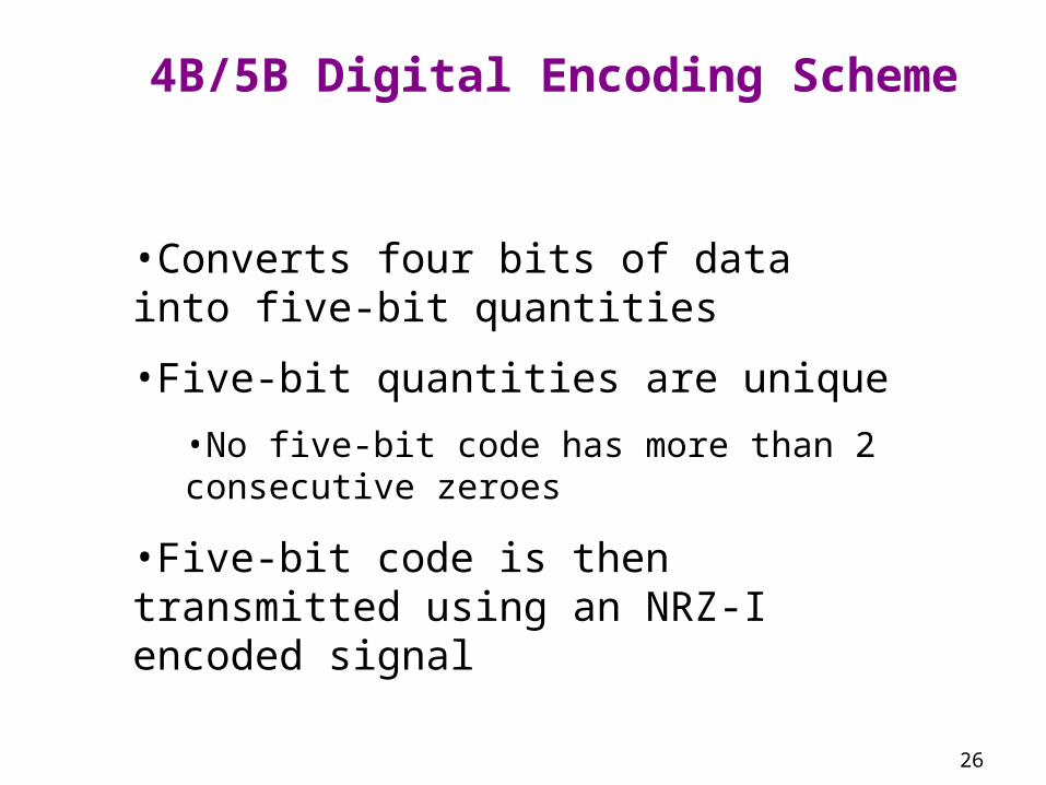
4B/5B Digital Encoding Scheme
•Converts four bits of data into five-bit quantities
•Five-bit quantities are unique
•No five-bit code has more than 2 consecutive zeroes
•Five-bit code is then transmitted using an NRZ-I encoded signal

27
4B/5B Digital Encoding Scheme (continued)

28
Transmitting Digital Data with Analog Signals
Three basic techniques:
• Amplitude shift keying
• Frequency shift keying
• Phase shift keying

29
Amplitude Shift Keying
•One amplitude encodes a 0 while another amplitude encodes a 1 (a form of amplitude modulation)

30
Amplitude Shift Keying (continued)
•Some systems use multiple amplitudes

31
Transmitting Digital Data with AnalogSignals (continued)
Multiple Signal Levels•Why use multiple signal levels?
•We can represent two levels with a single bit, 0 or 1
•We can represent four levels with two bits: 00, 01, 10, 11
•We can represent eight levels with three bits: 000, 001, 010, 011, 100, 101, 110, 111
•Note that the number of levels is always a power of 2

32
Frequency Shift Keying
•One frequency encodes a 0 while another frequency encodes a 1 (a form of frequency modulation)
33
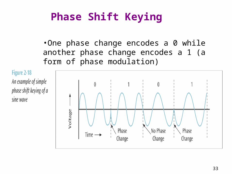
Phase Shift Keying
•One phase change encodes a 0 while another phase change encodes a 1 (a form of phase modulation)

34
Phase Shift Keying (continued)
Quadrature Phase Shift Keying
•Four different phase angles are used:
•45 degrees
•135 degrees
•225 degrees
•315 degrees

35
Phase Shift Keying (continued)
36
Phase Shift Keying (continued)
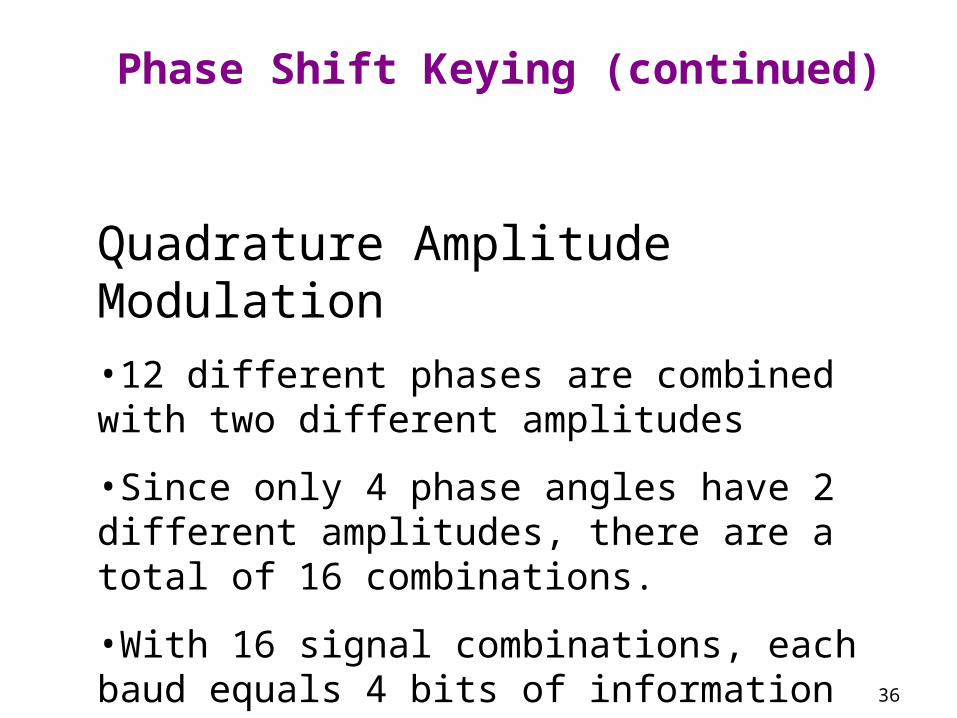
Quadrature Amplitude Modulation
•12 different phases are combined with two different amplitudes
•Since only 4 phase angles have 2 different amplitudes, there are a total of 16 combinations.
•With 16 signal combinations, each baud equals 4 bits of information (2 ^ 4 = 16)

37
Phase Shift Keying (continued)

38
Higher Data Transfer Rates
How do you send data faster?
1. Use a higher frequency signal (make sure the medium can handle the higher frequency)
2. Use a higher number of signal levels
In both cases, noise can be a problem

39
Maximum Data Transfer Rates
•How do you calculate a maximum data rate?
•Use Shannon’s equation:
S(f) = f log2 (1 + W/N)
Where f = signal frequency (bandwidth), W is signal power, and N is noise power

40
Maximum Data Transfer Rates (continued)
•For example, what is the data rate of a 3400 Hz signal with 0.2 watts of power and 0.0002 watts of noise?
S(f) = 3400 x log2 (1 + 0.2/0.0002)
= 3400 x log2 (1001)
= 3400 x 9.97
= 33898 bps

41
Transmitting Analog Data with Digital Signals
•To convert analog data into a digital signal, there are two basic techniques:
•Pulse code modulation (used by telephone systems)
•Delta modulation

42
Pulse Code Modulation
•Analog waveform is sampled at specific intervals
•“Snapshots” are converted to binary values

43
Pulse Code Modulation (continued)
•Binary values are later converted to an analog signal
•Waveform similar to original results

44
Pulse Code Modulation (continued)
•The more snapshots taken in the same amount of time, or the more quantization levels, the better the resolution

45
Pulse Code Modulation (continued)
•Because the human voice has a fairly narrow bandwidth
•Telephone systems digitize voice into either 128 levels or 256 levels
•Called quantization levels
•If 128 levels, then each sample is 7 bits (2 ^ 7 = 128)
•If 256 levels, then each sample is 8 bits (2 ^ 8 = 256)

46
Pulse Code Modulation (continued)
•How fast do you have to sample an input source to get a fairly accurate representation?
•Nyquist says 2 times the bandwidth
•Thus, if you want to digitize voice (4000 Hz), you need to sample at 8000 samples per second

47
Delta Modulation
•An analog waveform is tracked using a binary 1 to represent a rise in voltage and a 0 to represent a drop

48
Spread Spectrum Technology
•A secure encoding technique that uses multiple frequencies or codes to transmit data
•Two basic spread spectrum technologies:
•Frequency hopping spread spectrum
•Direct sequence spread spectrum

49
Spread Spectrum Technology (continued)

50
Spread Spectrum Technology (continued)
Direct Sequence Spread Spectrum
•This technology replaces each binary 0 and binary 1 with a unique pattern, or sequence, of 1s and 0s
•For example, one transmitter may transmit the sequence 10010100 for each binary 1, and 11001010 for each binary 0
•Another transmitter may transmit the sequence 11110000 for each binary 1, and 10101010 for each binary 0

51
Data Codes
•Data Code - set of all textual characters or symbols and their corresponding binary patterns
•Two basic data code sets plus a third code set that has interesting characteristics:
•EBCDIC
•ASCII
•Unicode

52
EBCDIC

53
ASCII

54
Data and Signal Conversions in Action: Two Examples
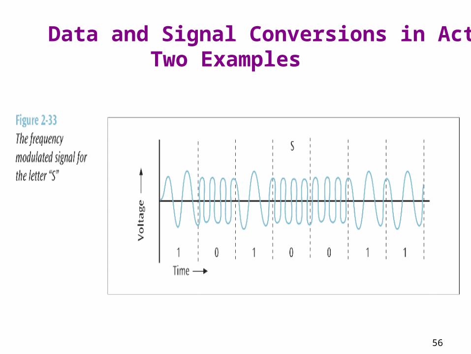
•Let us transmit the message “Sam, what time is the meeting with accounting? Hannah.”
•This message first leaves Hannah’s workstation and travels across a local area network

55
Data and Signal Conversions in Action: Two Examples
56
Data and Signal Conversions in Action: Two Examples

57
Summary
• Differences between digital and analog data and signals
• Components, bandwidth, and data transfer speed of signals
• Signal strength and attenuation• Basic digital encoding techniques• Shift keying (modulation) techniques• Spread Spectrum encoding techniques• Data codes in communication systems