Embed Size (px)
Citation preview

Chapter 2
From Extended Light Sourceto Collimated Illumination
2.1 Introduction
The collimation obtained in the manner shown in Fig. 1.10(b) uses a suitableprojection lens with diameter-to-focal-length ratios (d/F ) that are limited toabout 1:10 and do not yet require spherical correction. Many low-costmonochromats are available for optical components having large diameters.1
Optical component diameters must be compatible with the work they areexpected to perform. A 10-cm diameter needs a 1-m-long mechanical structure.Z folding makes the structure more compact. Antireflection coating of surfacesthat are not involved in interference formation is required.
A simple modification to the Newton testplating setup that is operatedwith collimated light is shown in Figs. 2.1(a) and (b). Figure 2.1(a) shows aSiC wafer under a reference at 0.25-mm distance under collimated obliqueincidence. The collimator is indicated only in Fig. 2.1(a). The sample and theadjusting feet of the reference rest on the same base. The base is a graniteplate, a glass plate, or a chuck. The adjustment to the sample distance uses aremovable lens-cleaning tissue, a cigarette paper, or a nylon string, which isremoved as the distance is increased.
Angle u can be derived from the reference holders [diameter d1 (crossingthe viewing direction) and d2 (in the viewing direction)], using
cosd1d2
� �¼ cos u, ð2:1Þ
if it is not known prior to recording.Any collimator can be used interchangeably with the contactless Newton
method as in Fig. 2.1(a), or with a flatness prism as in Figs. 1.4(b) and 2.1(c).A collimator arranged at 80-deg incidence to the operating base (a granite toolroom plate) will permit the use of the contactless Newton method on allsamples that could otherwise be testplated.
39
For use on prism interferometer devices, the same collimator needs adedicated direction. Finding and fixing the direction of the axis ofcollimated light toward the cathede of the 90-deg prism requires somepreparation. The process starts with the preferred orientation and heightof the prism parallel to and above the operating base. Application ofcalibration masters follows, as described in Chapter 1. The angle ofexcidence from the prism’s hypotenuse is the angle of incidence to thesample arranged parallel to the hypotenuse, at some safe distance that is onthe order of less than 1 mm. This angle must become known, as it determines
Figure 2.1(b) A SiC wafer of diameter 50 mm under a mercury spectral lamp without afilter. The gap is approximately 0.2 mm, recorded from the setup in Fig. 2.1(a).
Figure 2.1(a) The contactless Newton method generates information equivalent to thatgenerated by the Fizeau method but in a more effective manner.
40 Chapter 2
the fringe equivalent; it can be arranged for between 1 and 5 mm by selectingand fixing the collimator’s direction.
Figures 2.1(c) and (d) [and Fig. 1.14(b)] show simple, low-cost surfacetesting with the prism used as a loose component in direct contact.A calibration master automatically fulfills the parallel condition; three tinytape spacers can be beneficial. An inexpensive, handy, small, 90-deg prismmay be used for quick in-production visual inspection of technical surfaces.The interference image will be seen on a transparent paper as shown inFig. 2.1(d), using collimated light as in Fig. 1.14(b).
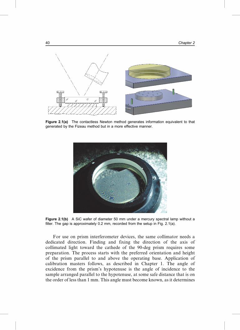
Figure 2.1(c) The flatness 90-deg prism used with the same collimator as in contactlessFizeau testplating in Fig. 1.14(c). The angle of incidence is marked by a thin fiducial line onthe edge of the first cathede, coinciding with calibrated marks on the second cathede. Thehypotenuse protrudes approximately 0.3 mm outside of the frame, which is designed to beasymmetric for weight balance. This is a very handy device for general optical shop utility.The three air-bearing feet allow for lateral scanning, for instance, on a granite surface plate.The three support rods serve in fringe alignment.
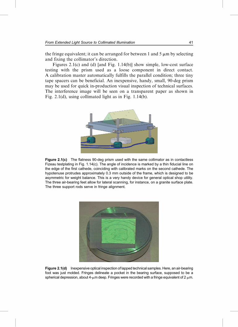
Figure 2.1(d) Inexpensive optical inspection of lapped technical samples.Here, anair-bearingfoot was just molded. Fringes delineate a pocket in the bearing surface, supposed to be aspherical depression, about 4-mmdeep. Fringes were recorded with a fringe equivalent of 2 mm.
41From Extended Light Source to Collimated Illumination

Results of this procedure include:
• The contact Newton method can be replaced by the contactless Fizeaumethod.
• The method allows for noncritical sample handling and adjustment forsuitable beam inclination.
• The procedure allows for a convenient selection of angles u of incidence.• Use of lasers and laser diodes requires limitation of their power tocomply with eye-protection regulations.
• On an air-bearing slide and after suitable alignment, a large sample canbe transported laterally and, thus, can be tested by scanning.
• The procedure is useful for quality control and machine alignment; abar of aluminum, micromachined to, e.g., 50 � 450 mm, indicates bothperfect flatness and alignment in the rare case where fringes maintainboth their initial spacing and their orientation at any other location(without walking during motion).
2.2 Technical Relevance of Oblique Incidence
A surprisingly large number of mass-produced products are specified to be flatto their edge, with a majority of these in the category of several centimeters indiameter. 100% quality assurance to about 1-mm departure from planarity iscommon. The fringe equivalent is selected to allow fast, simple interpretationof the permitted tolerance, e.g., 1 mm per fringe. This number is convenientlyreadable for untrained workshop personnel.
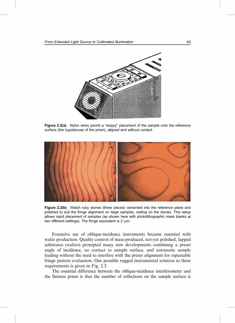
Most products to be tested require, time and again, quick and easyplacement of the sample at the proper distance from the reference, withoutthe need for subsequent alignment. A key problem here is often the lackparallelism in the sample; the bottom surface to be tested might be so far offof any commensurate clamping zone that sample alignment hardwarebecomes necessary. Instant sample alignment involves simply placing thesample onto the hypotenuse of the prism, now facing upwards, afterinterlaying some stretched nylon wires [Fig. 2.2(a)], or cementing watch rubystones into the reference surface and polishing them to the desired height[Fig. 2.2(b)].
The temptation to place objects directly onto the bare hypotenuse [asin Fig. 2.2(c)] is understandable; however, eventually, the referencesurface will become scratched. A low-cost repair solution uses immersionoil and a flat reference glass [Fig. 2.2(d)]. Such a plate can be a precision-polished quartz plate or a selected cut from low-cost float glass2
(available at 10- to 25-mm thickness). For refractive index of oils seeSection 7.7.1 and Ref. 3. For less-than-strict requirements, water white oruniversal oil suffices.
42 Chapter 2
Extensive use of oblique-incidence instruments became essential withwafer production. Quality control of mass-produced, not-yet polished, lappedsubstrates (wafers) prompted many new developments combining a presetangle of incidence, no contact to sample surface, and automatic samplefeeding without the need to interfere with the preset alignment for repeatablefringe pattern evaluation. One possible rugged instrumental solution to theserequirements is given in Fig. 2.3.
The essential difference between the oblique-incidence interferometer andthe flatness prism is that the number of reflections on the sample surface is
Figure 2.2(a) Nylon wires permit a “sloppy” placement of the sample onto the referencesurface (the hypotenuse of the prism), aligned and without contact.
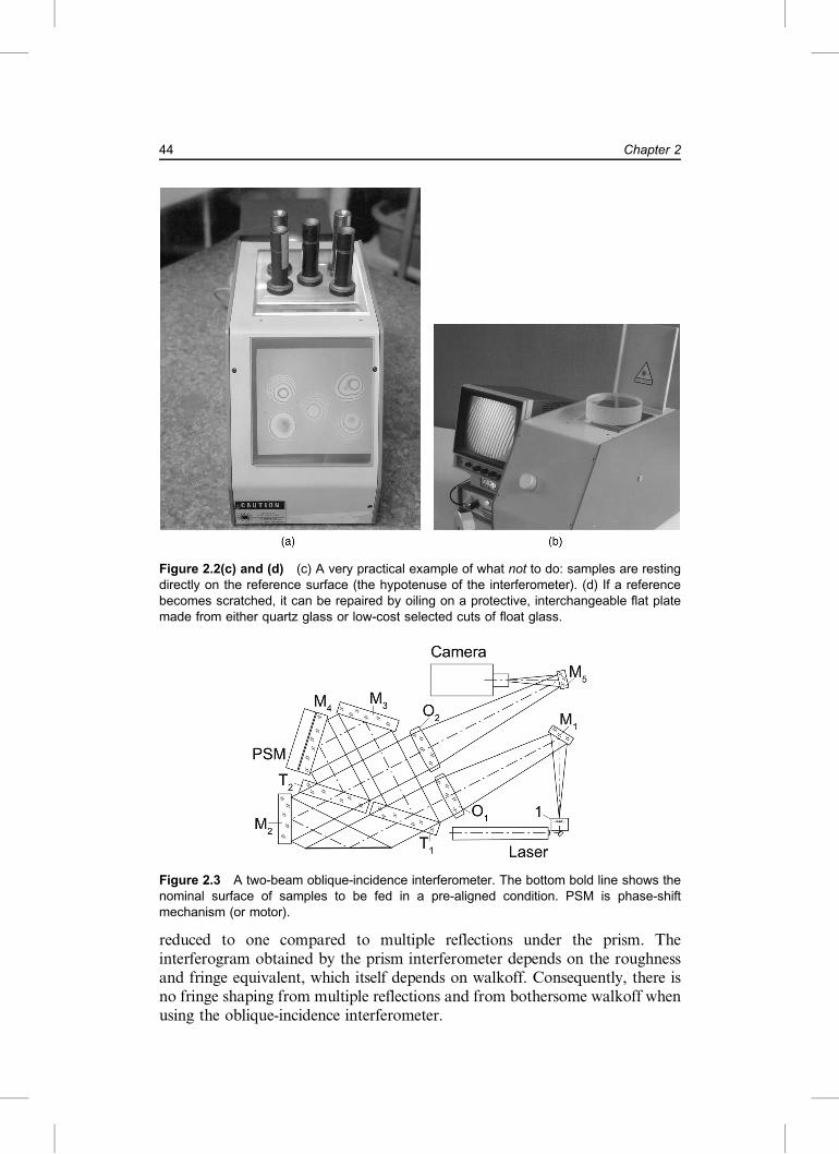
Figure 2.2(b) Watch ruby stones (three pieces) cemented into the reference plane andpolished to suit the fringe alignment on large samples, resting on the stones. This setupallows rapid placement of samples (as shown here with photolithographic mask blanks attwo different settings). The fringe equivalent is 2 mm.
43From Extended Light Source to Collimated Illumination
reduced to one compared to multiple reflections under the prism. Theinterferogram obtained by the prism interferometer depends on the roughnessand fringe equivalent, which itself depends on walkoff. Consequently, there isno fringe shaping from multiple reflections and from bothersome walkoff whenusing the oblique-incidence interferometer.
Figure 2.2(c) and (d) (c) A very practical example of what not to do: samples are restingdirectly on the reference surface (the hypotenuse of the interferometer). (d) If a referencebecomes scratched, it can be repaired by oiling on a protective, interchangeable flat platemade from either quartz glass or low-cost selected cuts of float glass.
Figure 2.3 A two-beam oblique-incidence interferometer. The bottom bold line shows thenominal surface of samples to be fed in a pre-aligned condition. PSM is phase-shiftmechanism (or motor).
44 Chapter 2


ÄÖÜÅØÆOEÇ}](https://img.pdfslide.us/doc/110x75/5e7d276657ac6a0bfb179a86/torcao-cdn-basic-extended-samples-torcao-extended-light-sphinx-of-black-quartz.jpg)