Embed Size (px)
Citation preview
Chapter 2
Experimental Setup
42
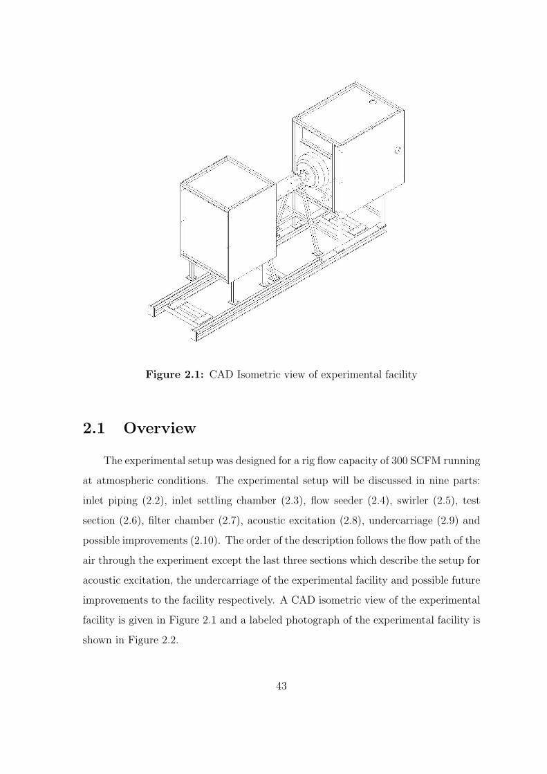
Figure 2.1: CAD Isometric view of experimental facility
2.1 Overview
The experimental setup was designed for a rig flow capacity of 300 SCFM running
at atmospheric conditions. The experimental setup will be discussed in nine parts:
inlet piping (2.2), inlet settling chamber (2.3), flow seeder (2.4), swirler (2.5), test
section (2.6), filter chamber (2.7), acoustic excitation (2.8), undercarriage (2.9) and
possible improvements (2.10). The order of the description follows the flow path of the
air through the experiment except the last three sections which describe the setup for
acoustic excitation, the undercarriage of the experimental facility and possible future
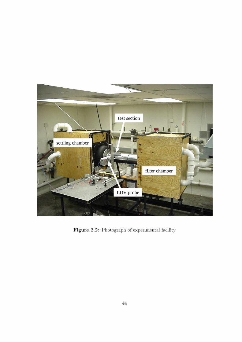
improvements to the facility respectively. A CAD isometric view of the experimental
facility is given in Figure 2.1 and a labeled photograph of the experimental facility is
shown in Figure 2.2.
43
LDV probe
settling chamber
filter chamber
test section
Figure 2.2: Photograph of experimental facility
44
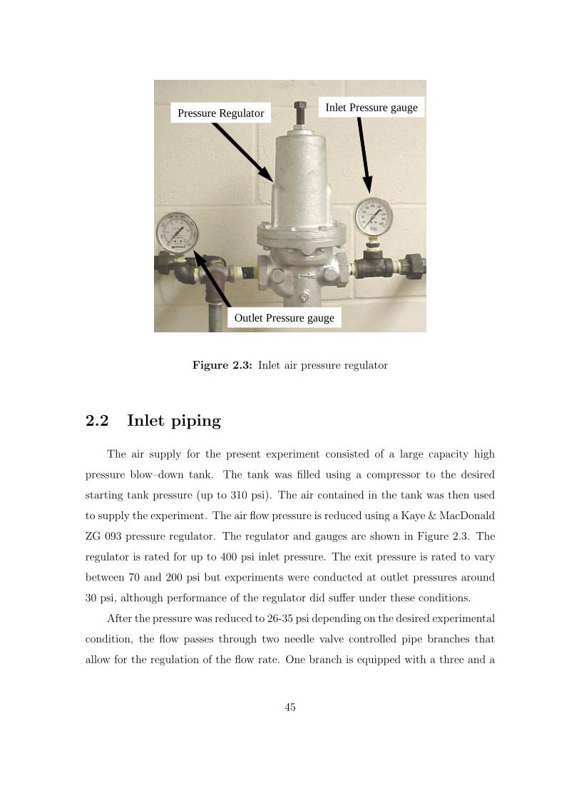
Outlet Pressure gauge
Pressure Regulator Inlet Pressure gauge
Figure 2.3: Inlet air pressure regulator
2.2 Inlet piping
The air supply for the present experiment consisted of a large capacity high
pressure blow–down tank. The tank was filled using a compressor to the desired
starting tank pressure (up to 310 psi). The air contained in the tank was then used
to supply the experiment. The air flow pressure is reduced using a Kaye & MacDonald
ZG 093 pressure regulator. The regulator and gauges are shown in Figure 2.3. The
regulator is rated for up to 400 psi inlet pressure. The exit pressure is rated to vary
between 70 and 200 psi but experiments were conducted at outlet pressures around
30 psi, although performance of the regulator did suffer under these conditions.
After the pressure was reduced to 26-35 psi depending on the desired experimental
condition, the flow passes through two needle valve controlled pipe branches that
allow for the regulation of the flow rate. One branch is equipped with a three and a
45
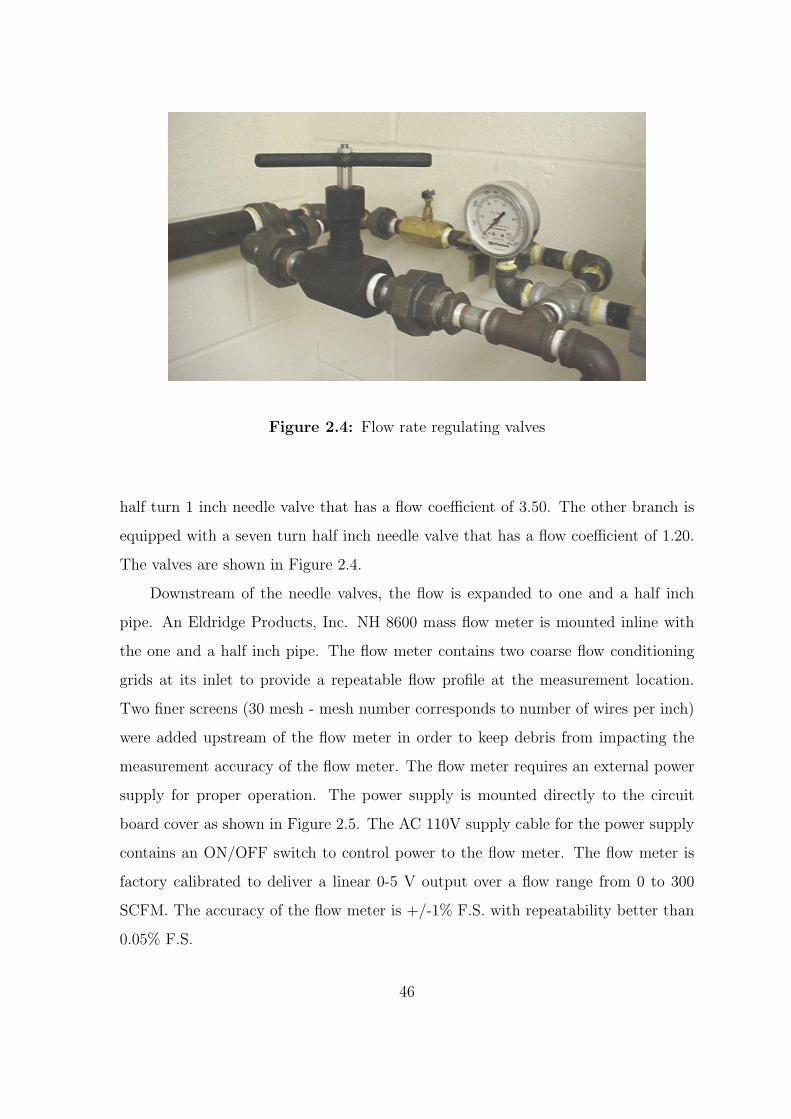
Figure 2.4: Flow rate regulating valves
half turn 1 inch needle valve that has a flow coefficient of 3.50. The other branch is
equipped with a seven turn half inch needle valve that has a flow coefficient of 1.20.
The valves are shown in Figure 2.4.
Downstream of the needle valves, the flow is expanded to one and a half inch
pipe. An Eldridge Products, Inc. NH 8600 mass flow meter is mounted inline with
the one and a half inch pipe. The flow meter contains two coarse flow conditioning
grids at its inlet to provide a repeatable flow profile at the measurement location.
Two finer screens (30 mesh - mesh number corresponds to number of wires per inch)
were added upstream of the flow meter in order to keep debris from impacting the
measurement accuracy of the flow meter. The flow meter requires an external power
supply for proper operation. The power supply is mounted directly to the circuit
board cover as shown in Figure 2.5. The AC 110V supply cable for the power supply
contains an ON/OFF switch to control power to the flow meter. The flow meter is
factory calibrated to deliver a linear 0-5 V output over a flow range from 0 to 300
SCFM. The accuracy of the flow meter is +/-1% F.S. with repeatability better than
0.05% F.S.
46
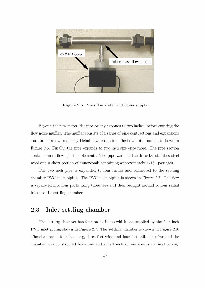
Power supply
Inline mass flow-meter
Figure 2.5: Mass flow meter and power supply
Beyond the flow meter, the pipe briefly expands to two inches, before entering the
flow noise muffler. The muffler consists of a series of pipe contractions and expansions
and an ultra low frequency Helmholtz resonator. The flow noise muffler is shown in
Figure 2.6. Finally, the pipe expands to two inch size once more. The pipe section
contains more flow quieting elements. The pipe was filled with rocks, stainless steel
wool and a short section of honeycomb containing approximately 1/16” passages.
The two inch pipe is expanded to four inches and connected to the settling
chamber PVC inlet piping. The PVC inlet piping is shown in Figure 2.7. The flow
is separated into four parts using three tees and then brought around to four radial
inlets to the settling chamber.
2.3 Inlet settling chamber
The settling chamber has four radial inlets which are supplied by the four inch
PVC inlet piping shown in Figure 2.7. The settling chamber is shown in Figure 2.8.
The chamber is four feet long, three feet wide and four feet tall. The frame of the
chamber was constructed from one and a half inch square steel structural tubing.
47
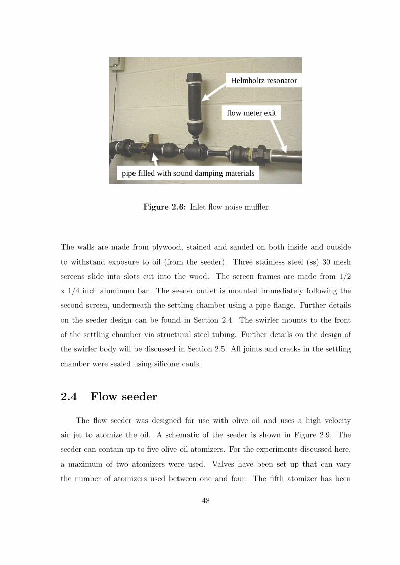
Helmholtz resonator
flow meter exit
pipe filled with sound damping materials
Figure 2.6: Inlet flow noise muffler
The walls are made from plywood, stained and sanded on both inside and outside
to withstand exposure to oil (from the seeder). Three stainless steel (ss) 30 mesh
screens slide into slots cut into the wood. The screen frames are made from 1/2
x 1/4 inch aluminum bar. The seeder outlet is mounted immediately following the
second screen, underneath the settling chamber using a pipe flange. Further details
on the seeder design can be found in Section 2.4. The swirler mounts to the front
of the settling chamber via structural steel tubing. Further details on the design of
the swirler body will be discussed in Section 2.5. All joints and cracks in the settling
chamber were sealed using silicone caulk.
2.4 Flow seeder
The flow seeder was designed for use with olive oil and uses a high velocity
air jet to atomize the oil. A schematic of the seeder is shown in Figure 2.9. The
seeder can contain up to five olive oil atomizers. For the experiments discussed here,
a maximum of two atomizers were used. Valves have been set up that can vary
the number of atomizers used between one and four. The fifth atomizer has been
48
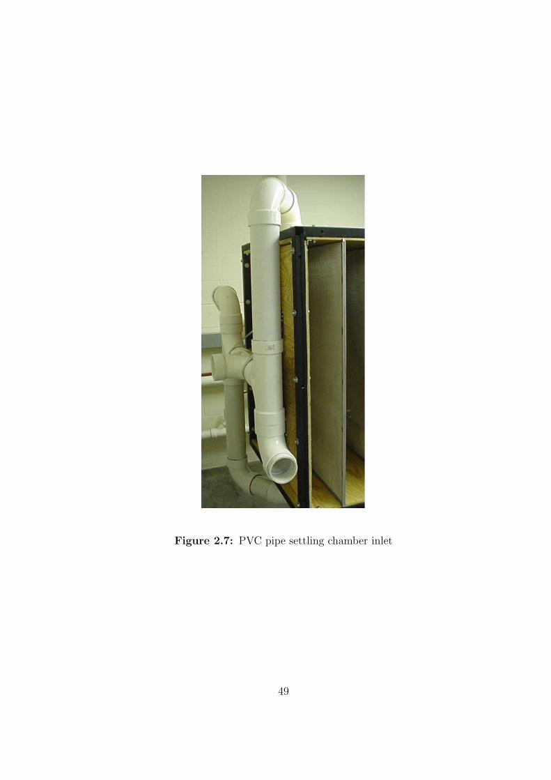
Figure 2.7: PVC pipe settling chamber inlet
49
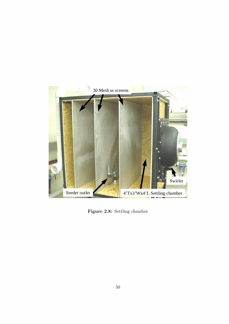
30 Mesh ss screens
Swirler
4’Tx3’Wx4’L Settling chamberSeeder outlet
Figure 2.8: Settling chamber
50
removed because it was not needed. A picture of an atomizer is shown in the inset
of Figure 2.10. Each atomizer consists of a capped aluminum tube. Four radial holes
(0.02” diameter) are drilled into the aluminum tube spaced at 90 degrees. A disk is
mounted just below these four holes. The disk itself also contains four small holes
of the same size. The holes are oriented at 90 degrees to the radial holes, parallel
to the aluminum tube. The air jet exits radially over the disk’s holes and due to
the jet’s locally lower pressure draws oil through the disk’s holes and atomizes the
oil into fine droplets. This mechanism of atomization functions even if the atomizers
themselves are submerged in olive oil. Larger droplets are prevented from exiting the
cavity by the droplet separator plate which only leaves a very small annular area for
the olive oil mist to escape. The thickness of annulus is approximately 0.032 inches.
Additionally, the one inch pipe exit of the seeder is threaded close to the top surface
of the separator plate providing an additional large droplet filter. The design closely
follows that recommended by TSI Inc., manufacturer of complete LDV systems for
LDV operation. A photograph of the seeder is shown in Figure 2.10.
2.5 Swirler
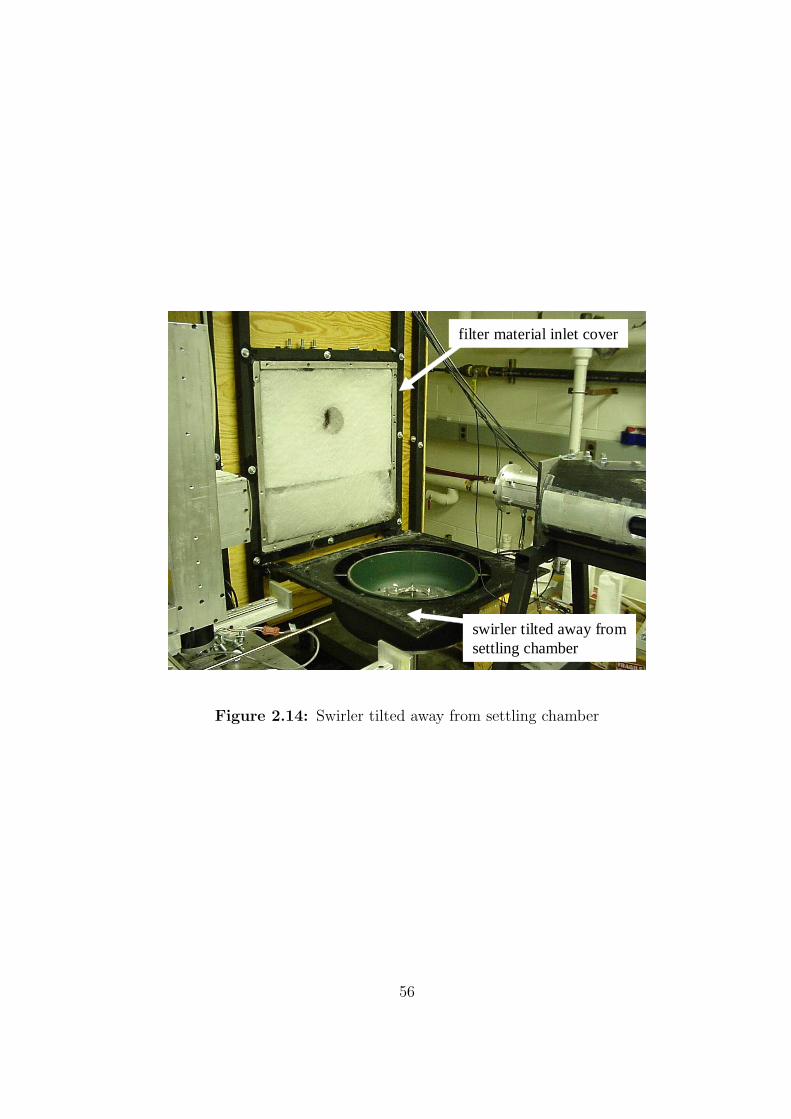
The swirler is bolted to the end of the settling chamber. A photograph of the front
of the swirler is shown in Figure 2.11. The swirler is shown uncovered in Figure 2.12.
In addition to the bolts, the swirler is also connected to the settling chamber via a
rotating joint (shown in Figure 2.13), that allows the swirler, when unbolted to be
tilted away from the settling chamber without removing the swirler all together. The
swirler is shown rotated away from the settling chamber in Figure 2.14.
Some relatively coarse filter material (relative to the HEPA filter in the filter
chamber) is added to the annular swirler inlet to help distribute the flow evenly in
the annulus. The covered inlet can be seen in Figure 2.14 and is also shown in
Figure 2.15.
The swirler body is made from two large carbon steel pipe caps. An exploded
view of the swirler body is shown in Figure 2.17. The outer shell of the swirler is
51
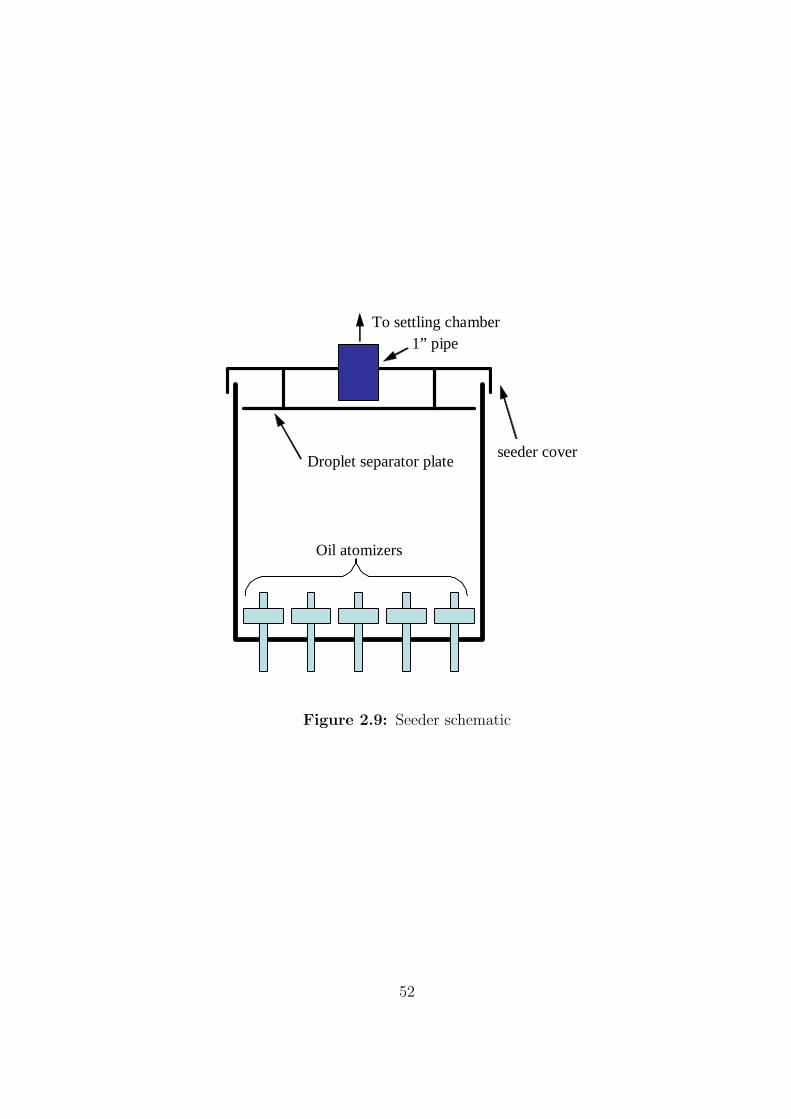
To settling chamber
seeder coverDroplet separator plate
Oil atomizers
1” pipe
Figure 2.9: Seeder schematic
52
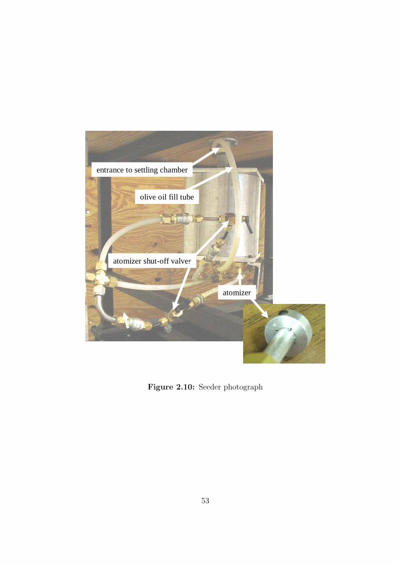
atomizer
olive oil fill tube
entrance to settling chamber
atomizer shut-off valves
Figure 2.10: Seeder photograph
53
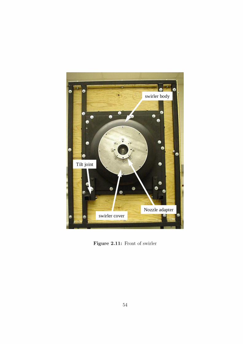
swirler body
Nozzle adapter
Tilt joint
swirler cover
Figure 2.11: Front of swirler
54
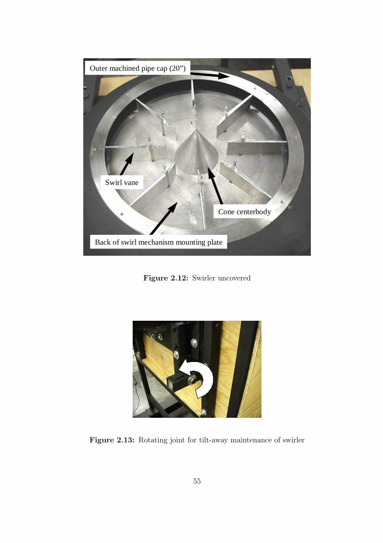
Swirl vane
Cone centerbody
Outer machined pipe cap (20”)
Back of swirl mechanism mounting plate
Figure 2.12: Swirler uncovered
Figure 2.13: Rotating joint for tilt-away maintenance of swirler
55
swirler tilted away fromsettling chamber
filter material inlet cover
Figure 2.14: Swirler tilted away from settling chamber
56
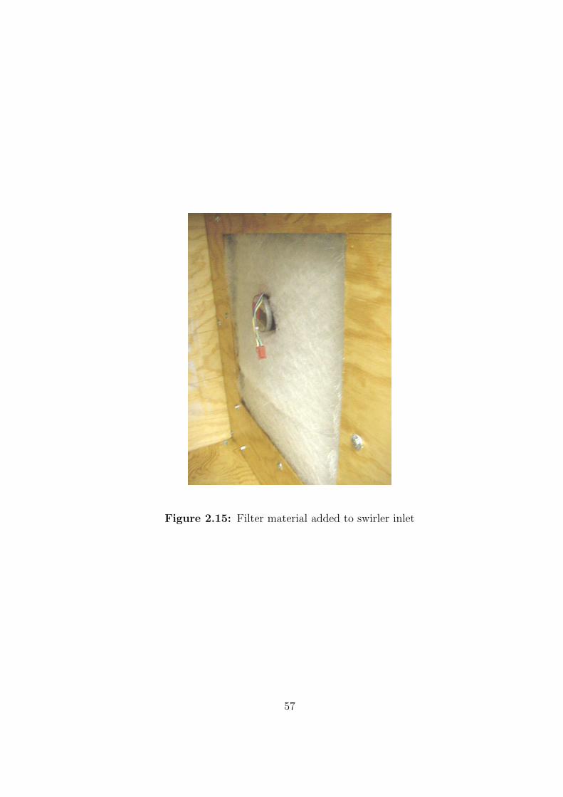
Figure 2.15: Filter material added to swirler inlet
57
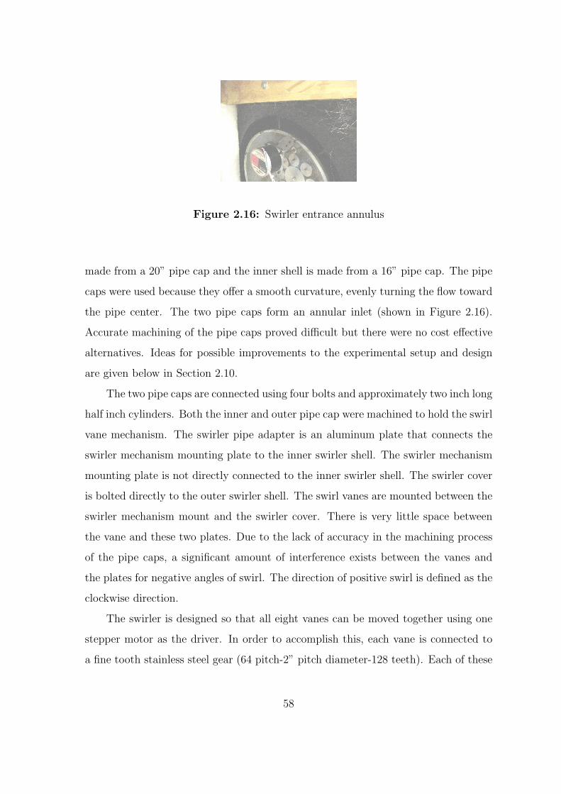
Figure 2.16: Swirler entrance annulus
made from a 20” pipe cap and the inner shell is made from a 16” pipe cap. The pipe
caps were used because they offer a smooth curvature, evenly turning the flow toward
the pipe center. The two pipe caps form an annular inlet (shown in Figure 2.16).
Accurate machining of the pipe caps proved difficult but there were no cost effective
alternatives. Ideas for possible improvements to the experimental setup and design
are given below in Section 2.10.
The two pipe caps are connected using four bolts and approximately two inch long
half inch cylinders. Both the inner and outer pipe cap were machined to hold the swirl
vane mechanism. The swirler pipe adapter is an aluminum plate that connects the
swirler mechanism mounting plate to the inner swirler shell. The swirler mechanism
mounting plate is not directly connected to the inner swirler shell. The swirler cover
is bolted directly to the outer swirler shell. The swirl vanes are mounted between the
swirler mechanism mount and the swirler cover. There is very little space between
the vane and these two plates. Due to the lack of accuracy in the machining process
of the pipe caps, a significant amount of interference exists between the vanes and
the plates for negative angles of swirl. The direction of positive swirl is defined as the
clockwise direction.
The swirler is designed so that all eight vanes can be moved together using one
stepper motor as the driver. In order to accomplish this, each vane is connected to
a fine tooth stainless steel gear (64 pitch-2” pitch diameter-128 teeth). Each of these
58
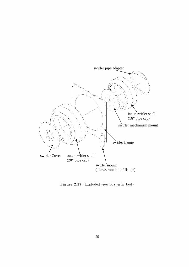
swirler Cover outer swirler shell (20” pipe cap)
swirler flange
swirler mount(allows rotation of flange)
swirler mechanism mount
inner swirler shell(16” pipe cap)
swirler pipe adapter
Figure 2.17: Exploded view of swirler body
59
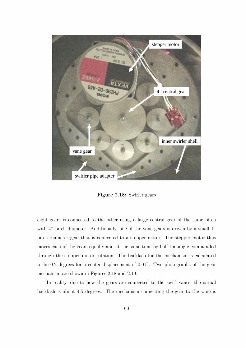
inner swirler shell
swirler pipe adapter
4” central gear
vane gear
stepper motor
Figure 2.18: Swirler gears
eight gears is connected to the other using a large central gear of the same pitch
with 4” pitch diameter. Additionally, one of the vane gears is driven by a small 1”
pitch diameter gear that is connected to a stepper motor. The stepper motor thus
moves each of the gears equally and at the same time by half the angle commanded
through the stepper motor rotation. The backlash for the mechanism is calculated
to be 0.2 degrees for a center displacement of 0.01”. Two photographs of the gear
mechanism are shown in Figures 2.18 and 2.19.
In reality, due to how the gears are connected to the swirl vanes, the actual
backlash is about 4.5 degrees. The mechanism connecting the gear to the vane is
60
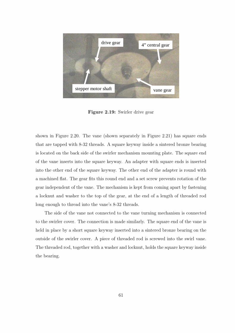
stepper motor shaft
4” central gear
vane gear
drive gear
Figure 2.19: Swirler drive gear
shown in Figure 2.20. The vane (shown separately in Figure 2.21) has square ends
that are tapped with 8-32 threads. A square keyway inside a sintered bronze bearing
is located on the back side of the swirler mechanism mounting plate. The square end
of the vane inserts into the square keyway. An adapter with square ends is inserted
into the other end of the square keyway. The other end of the adapter is round with
a machined flat. The gear fits this round end and a set screw prevents rotation of the
gear independent of the vane. The mechanism is kept from coming apart by fastening
a locknut and washer to the top of the gear, at the end of a length of threaded rod
long enough to thread into the vane’s 8-32 threads.
The side of the vane not connected to the vane turning mechanism is connected
to the swirler cover. The connection is made similarly. The square end of the vane is
held in place by a short square keyway inserted into a sintered bronze bearing on the
outside of the swirler cover. A piece of threaded rod is screwed into the swirl vane.
The threaded rod, together with a washer and locknut, holds the square keyway inside
the bearing.
61
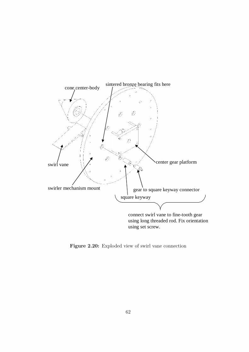
swirl vane
swirler mechanism mount gear to square keyway connector
square keyway
center gear platform
cone center-body
connect swirl vane to fine-tooth gearusing long threaded rod. Fix orientationusing set screw.
sintered bronze bearing fits here
Figure 2.20: Exploded view of swirl vane connection
62
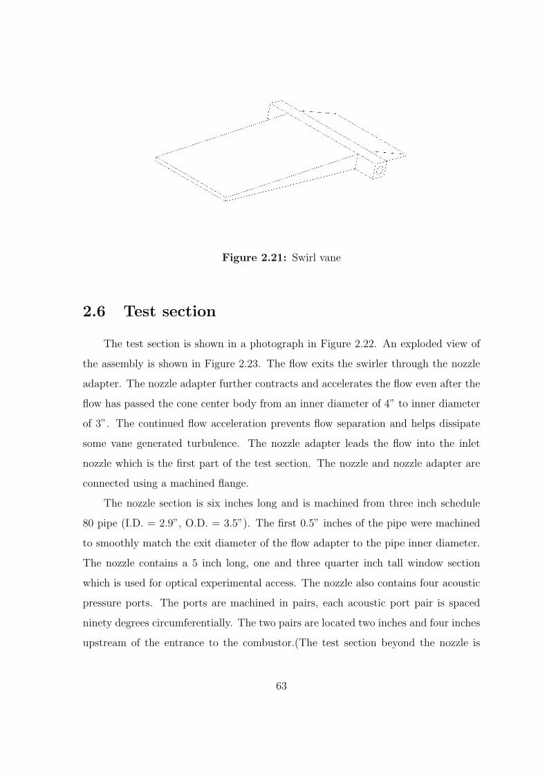
Figure 2.21: Swirl vane
2.6 Test section
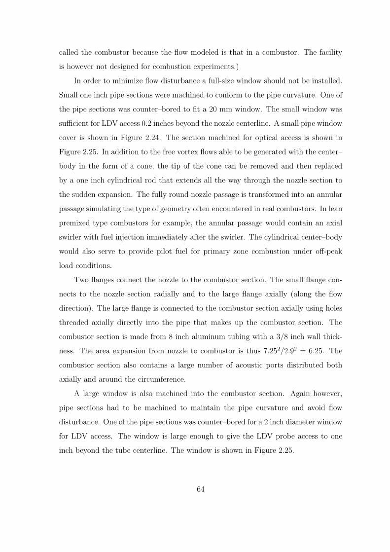
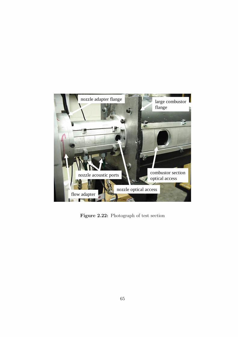
The test section is shown in a photograph in Figure 2.22. An exploded view of
the assembly is shown in Figure 2.23. The flow exits the swirler through the nozzle
adapter. The nozzle adapter further contracts and accelerates the flow even after the
flow has passed the cone center body from an inner diameter of 4” to inner diameter
of 3”. The continued flow acceleration prevents flow separation and helps dissipate
some vane generated turbulence. The nozzle adapter leads the flow into the inlet
nozzle which is the first part of the test section. The nozzle and nozzle adapter are
connected using a machined flange.
The nozzle section is six inches long and is machined from three inch schedule
80 pipe (I.D. = 2.9”, O.D. = 3.5”). The first 0.5” inches of the pipe were machined
to smoothly match the exit diameter of the flow adapter to the pipe inner diameter.
The nozzle contains a 5 inch long, one and three quarter inch tall window section
which is used for optical experimental access. The nozzle also contains four acoustic
pressure ports. The ports are machined in pairs, each acoustic port pair is spaced
ninety degrees circumferentially. The two pairs are located two inches and four inches
upstream of the entrance to the combustor.(The test section beyond the nozzle is
63
called the combustor because the flow modeled is that in a combustor. The facility
is however not designed for combustion experiments.)
In order to minimize flow disturbance a full-size window should not be installed.
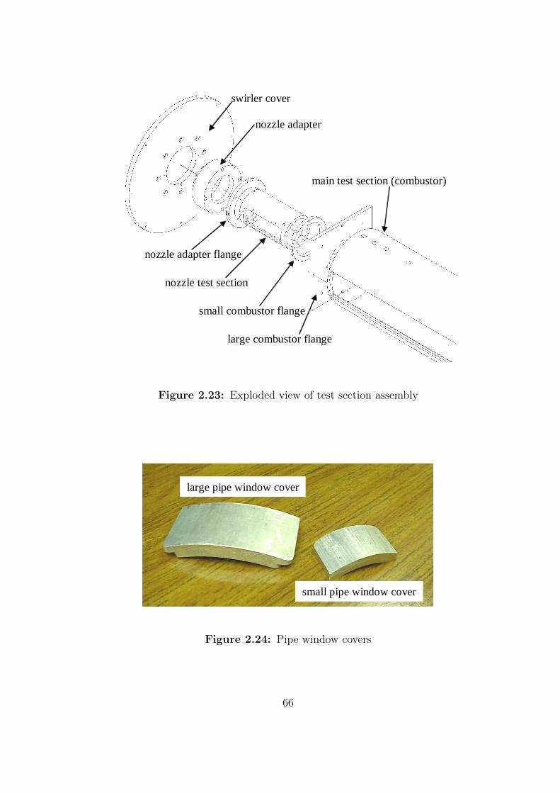
Small one inch pipe sections were machined to conform to the pipe curvature. One of
the pipe sections was counter–bored to fit a 20 mm window. The small window was
sufficient for LDV access 0.2 inches beyond the nozzle centerline. A small pipe window
cover is shown in Figure 2.24. The section machined for optical access is shown in
Figure 2.25. In addition to the free vortex flows able to be generated with the center–
body in the form of a cone, the tip of the cone can be removed and then replaced
by a one inch cylindrical rod that extends all the way through the nozzle section to
the sudden expansion. The fully round nozzle passage is transformed into an annular
passage simulating the type of geometry often encountered in real combustors. In lean
premixed type combustors for example, the annular passage would contain an axial
swirler with fuel injection immediately after the swirler. The cylindrical center–body
would also serve to provide pilot fuel for primary zone combustion under off-peak
load conditions.
Two flanges connect the nozzle to the combustor section. The small flange con-
nects to the nozzle section radially and to the large flange axially (along the flow
direction). The large flange is connected to the combustor section axially using holes
threaded axially directly into the pipe that makes up the combustor section. The
combustor section is made from 8 inch aluminum tubing with a 3/8 inch wall thick-
ness. The area expansion from nozzle to combustor is thus 7.252/2.92 = 6.25. The
combustor section also contains a large number of acoustic ports distributed both
axially and around the circumference.
A large window is also machined into the combustor section. Again however,
pipe sections had to be machined to maintain the pipe curvature and avoid flow
disturbance. One of the pipe sections was counter–bored for a 2 inch diameter window
for LDV access. The window is large enough to give the LDV probe access to one
inch beyond the tube centerline. The window is shown in Figure 2.25.
64
nozzle optical access
large combustorflange
combustor sectionoptical access
nozzle adapter flange
flow adapter
nozzle acoustic ports
Figure 2.22: Photograph of test section
65
nozzle adapter flange
nozzle test section
large combustor flange
small combustor flange
main test section (combustor)
swirler cover
nozzle adapter
Figure 2.23: Exploded view of test section assembly
small pipe window cover
large pipe window cover
Figure 2.24: Pipe window covers
66
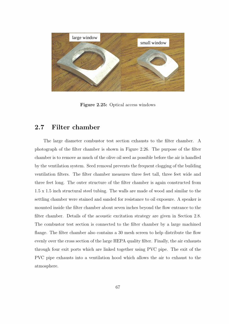
small windowlarge window
Figure 2.25: Optical access windows
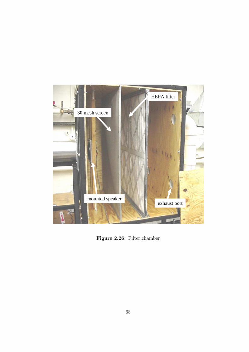
2.7 Filter chamber
The large diameter combustor test section exhausts to the filter chamber. A
photograph of the filter chamber is shown in Figure 2.26. The purpose of the filter
chamber is to remove as much of the olive oil seed as possible before the air is handled
by the ventilation system. Seed removal prevents the frequent clogging of the building
ventilation filters. The filter chamber measures three feet tall, three feet wide and
three feet long. The outer structure of the filter chamber is again constructed from
1.5 x 1.5 inch structural steel tubing. The walls are made of wood and similar to the
settling chamber were stained and sanded for resistance to oil exposure. A speaker is
mounted inside the filter chamber about seven inches beyond the flow entrance to the
filter chamber. Details of the acoustic excitation strategy are given in Section 2.8.
The combustor test section is connected to the filter chamber by a large machined
flange. The filter chamber also contains a 30 mesh screen to help distribute the flow
evenly over the cross section of the large HEPA quality filter. Finally, the air exhausts
through four exit ports which are linked together using PVC pipe. The exit of the
PVC pipe exhausts into a ventilation hood which allows the air to exhaust to the
atmosphere.
67
exhaust port
HEPA filter
mounted speaker
30 mesh screen
Figure 2.26: Filter chamber
68
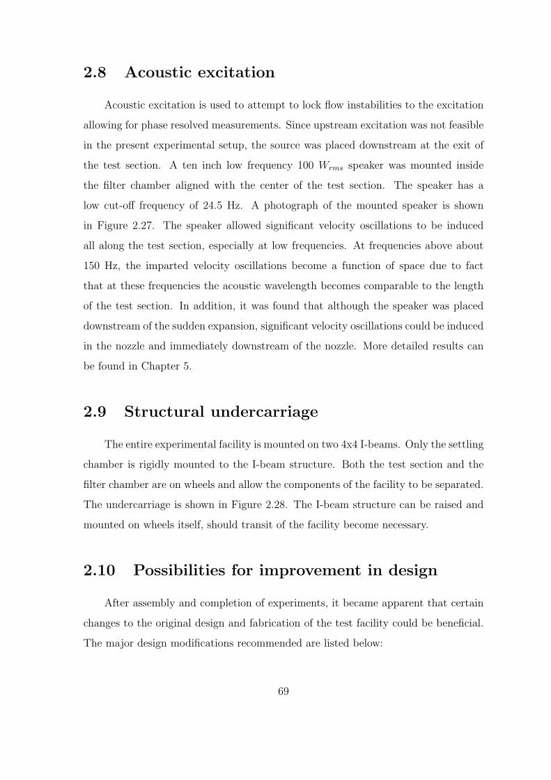
2.8 Acoustic excitation
Acoustic excitation is used to attempt to lock flow instabilities to the excitation
allowing for phase resolved measurements. Since upstream excitation was not feasible
in the present experimental setup, the source was placed downstream at the exit of
the test section. A ten inch low frequency 100 Wrms speaker was mounted inside
the filter chamber aligned with the center of the test section. The speaker has a
low cut-off frequency of 24.5 Hz. A photograph of the mounted speaker is shown
in Figure 2.27. The speaker allowed significant velocity oscillations to be induced
all along the test section, especially at low frequencies. At frequencies above about
150 Hz, the imparted velocity oscillations become a function of space due to fact
that at these frequencies the acoustic wavelength becomes comparable to the length
of the test section. In addition, it was found that although the speaker was placed
downstream of the sudden expansion, significant velocity oscillations could be induced
in the nozzle and immediately downstream of the nozzle. More detailed results can
be found in Chapter 5.
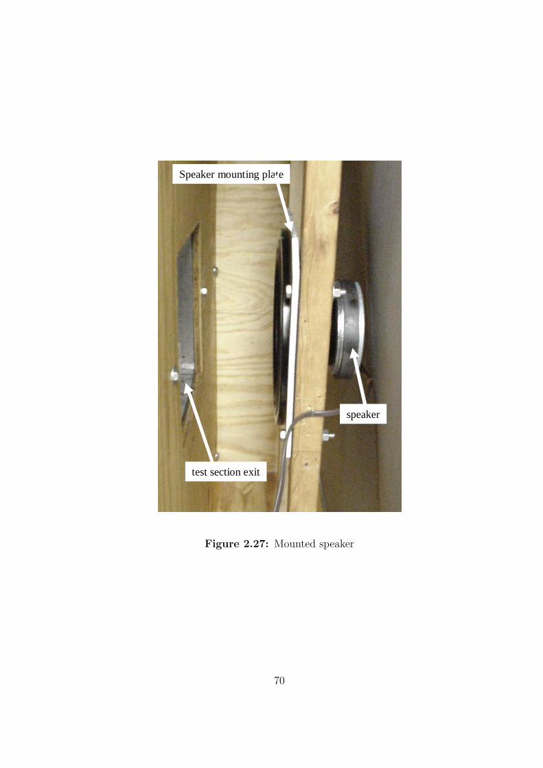
2.9 Structural undercarriage
The entire experimental facility is mounted on two 4x4 I-beams. Only the settling
chamber is rigidly mounted to the I-beam structure. Both the test section and the
filter chamber are on wheels and allow the components of the facility to be separated.
The undercarriage is shown in Figure 2.28. The I-beam structure can be raised and
mounted on wheels itself, should transit of the facility become necessary.
2.10 Possibilities for improvement in design
After assembly and completion of experiments, it became apparent that certain
changes to the original design and fabrication of the test facility could be beneficial.
The major design modifications recommended are listed below:
69
speaker
Speaker mounting plate
test section exit
Figure 2.27: Mounted speaker
70
wheel track4x4 I-beam base
filter chamberon wheels
test sectionon wheels
Figure 2.28: Undercarriage of experimental facility
• It is helpful to have visual access to the settling chamber swirler and filter
chamber. Plexiglass windows should be installed in the chambers and the swirler
cover should be machined out of Lexan (hard plexiglass).
• The large effort expended to obtain smooth turning of the flow into the swirl
vanes can be avoided by simply having the flow enter the swirler radially inside
the settling chamber. The swirl vane mechanism could be more accurately
mounted and swirl vane interference would not be a problem.
• The vane turning mechanism can be improved by removing the square key
way and replacing the adapter with one that has a rounded square female end.
Additionally, a set screw should be used to prevent relative motion between the
swirl vane and the adapter.
• A more precise connecting shaft should be used to hold the adapter, swirl vane
and gear together. The slop between the threaded rod and the adapter hole is
71
another source for backlash of the vane mechanism.
• The seeder should be redesigned for smaller capacity to allow better fine tuning
of the required seed level in a given experiment.
• A second pressure regulator should be installed in the high pressure air line
to minimize the number of adjustments needed for the valves and/or regulator
settings.
72