Embed Size (px)
DESCRIPTION
Chapter 2 Electrical Principles and PLCs. Programmable Logic Controllers and Electrical Principles • Voltage • Current • Resistance • Series Circuits • Parallel Circuits. - PowerPoint PPT Presentation
Citation preview
PowerPoint® Presentation
Chapter 2Electrical Principles and PLCs
Chapter 2Electrical Principles and PLCs
Programmable Logic Controllers and Electrical Principles • Voltage • Current • Resistance • Series
Circuits • Parallel Circuits
Chapter 2 — Electrical Principles and PLCs
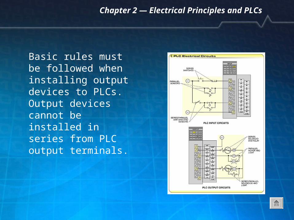
Basic rules must be followed when installing output devices to PLCs. Output devices cannot be installed in series from PLC output terminals.
Chapter 2 — Electrical Principles and PLCs
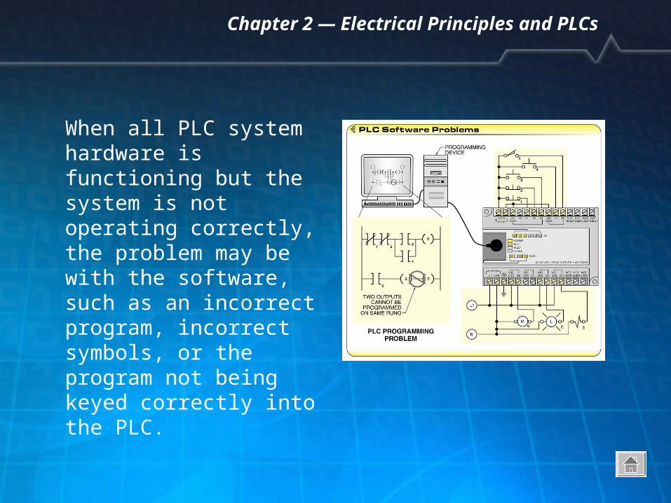
When all PLC system hardware is functioning but the system is not operating correctly, the problem may be with the software, such as an incorrect program, incorrect symbols, or the program not being keyed correctly into the PLC.
Chapter 2 — Electrical Principles and PLCs
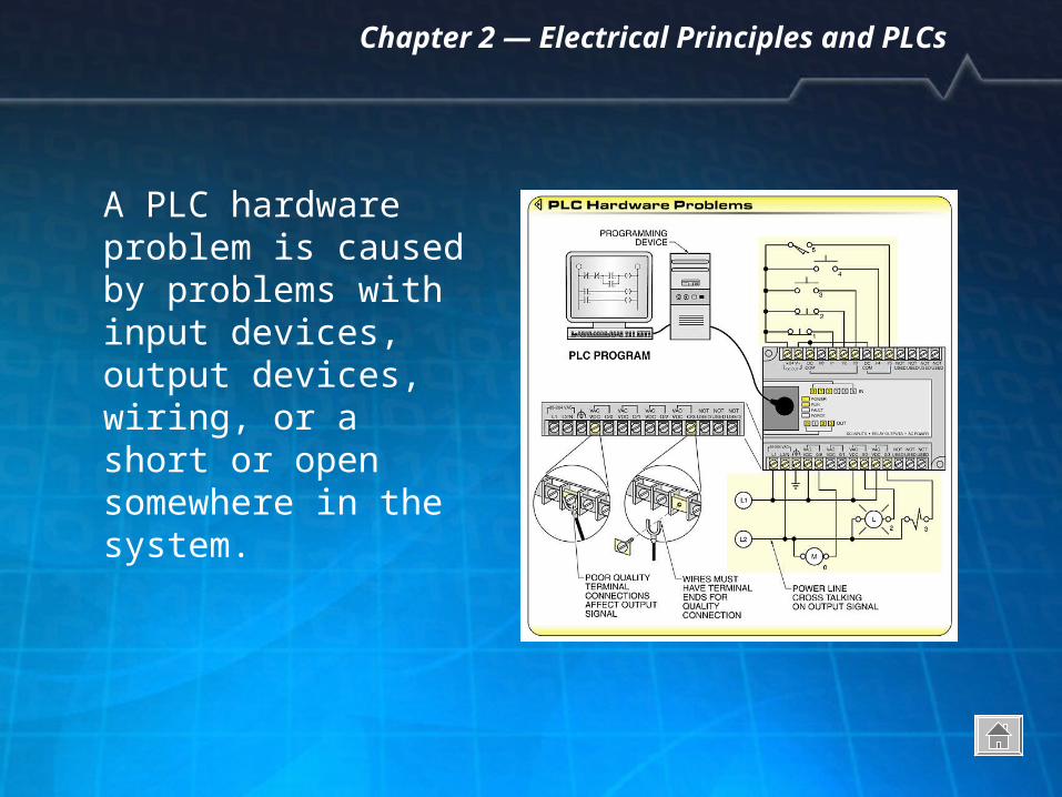
A PLC hardware problem is caused by problems with input devices, output devices, wiring, or a short or open somewhere in the system.
Chapter 2 — Electrical Principles and PLCs
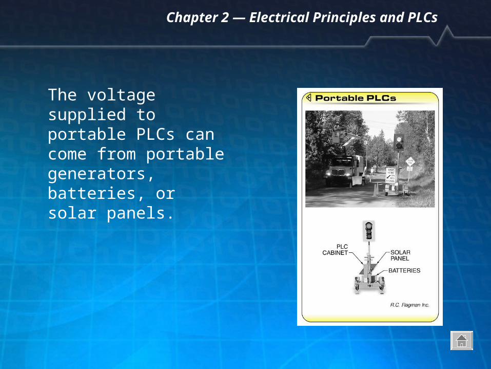
The voltage supplied to portable PLCs can come from portable generators, batteries, or solar panels.
Chapter 2 — Electrical Principles and PLCs
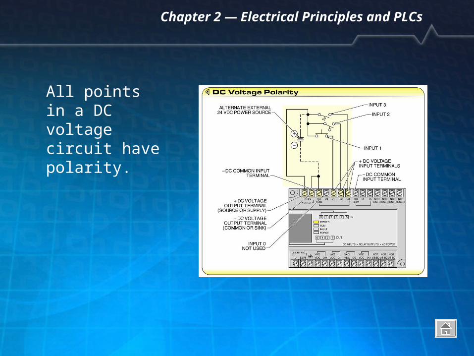
All points in a DC voltage circuit have polarity.
Chapter 2 — Electrical Principles and PLCs
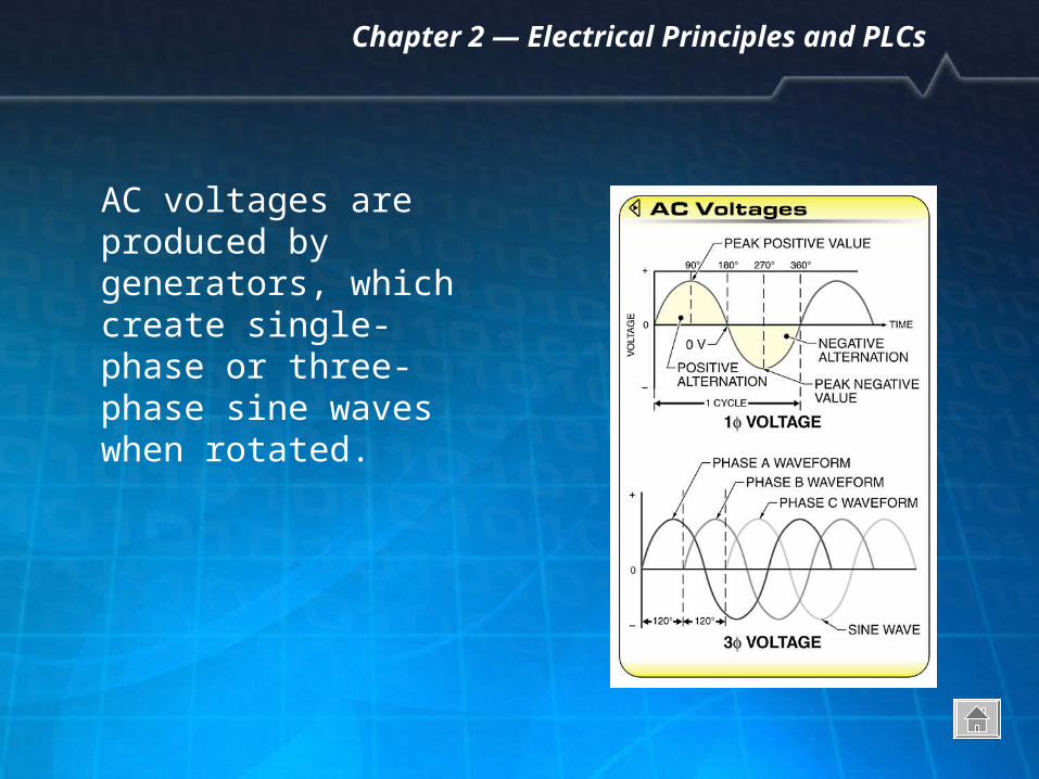
AC voltages are produced by generators, which create single-phase or three-phase sine waves when rotated.
Chapter 2 — Electrical Principles and PLCs
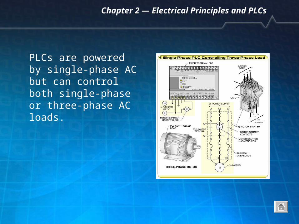
PLCs are powered by single-phase AC but can control both single-phase or three-phase AC loads.
Chapter 2 — Electrical Principles and PLCs
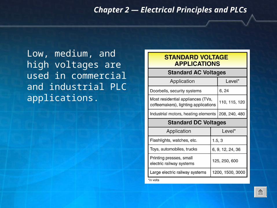
Low, medium, and high voltages are used in commercial and industrial PLC applications.
Chapter 2 — Electrical Principles and PLCs
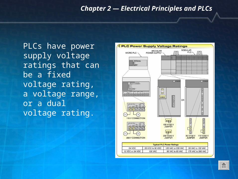
PLCs have power supply voltage ratings that can be a fixed voltage rating, a voltage range, or a dual voltage rating.
Chapter 2 — Electrical Principles and PLCs
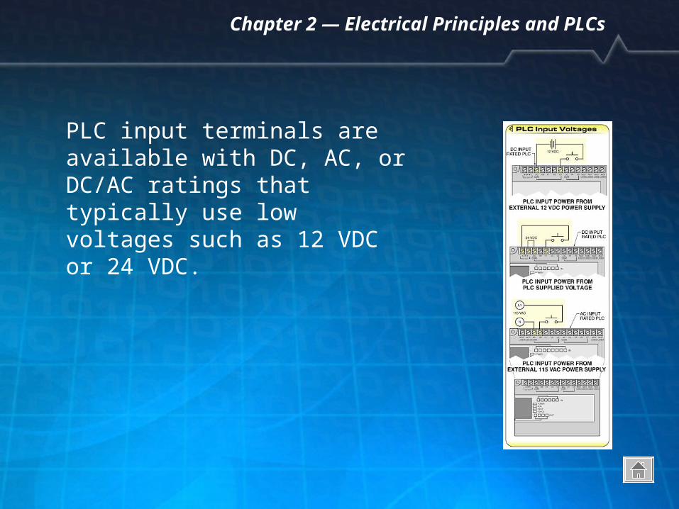
PLC input terminals are available with DC, AC, or DC/AC ratings that typically use low voltages such as 12 VDC or 24 VDC.
Chapter 2 — Electrical Principles and PLCs
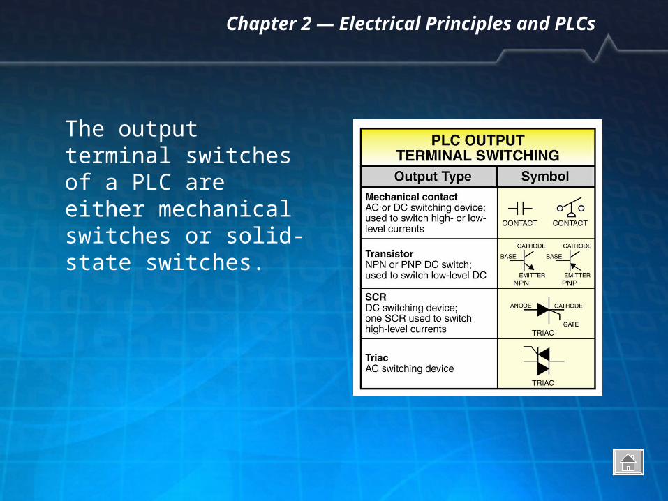
The output terminal switches of a PLC are either mechanical switches or solid-state switches.
Chapter 2 — Electrical Principles and PLCs
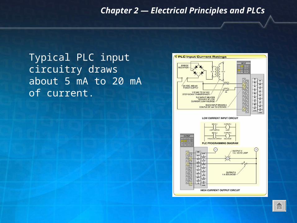
Typical PLC input circuitry draws about 5 mA to 20 mA of current.
Chapter 2 — Electrical Principles and PLCs
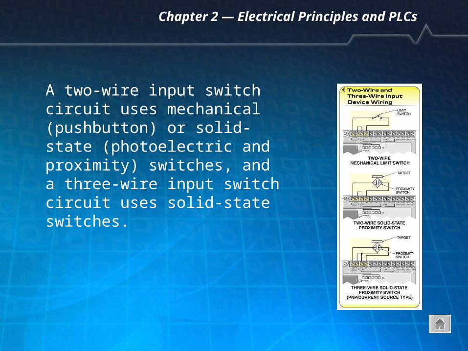
A two-wire input switch circuit uses mechanical (pushbutton) or solid-state (photoelectric and proximity) switches, and a three-wire input switch circuit uses solid-state switches.
Chapter 2 — Electrical Principles and PLCs
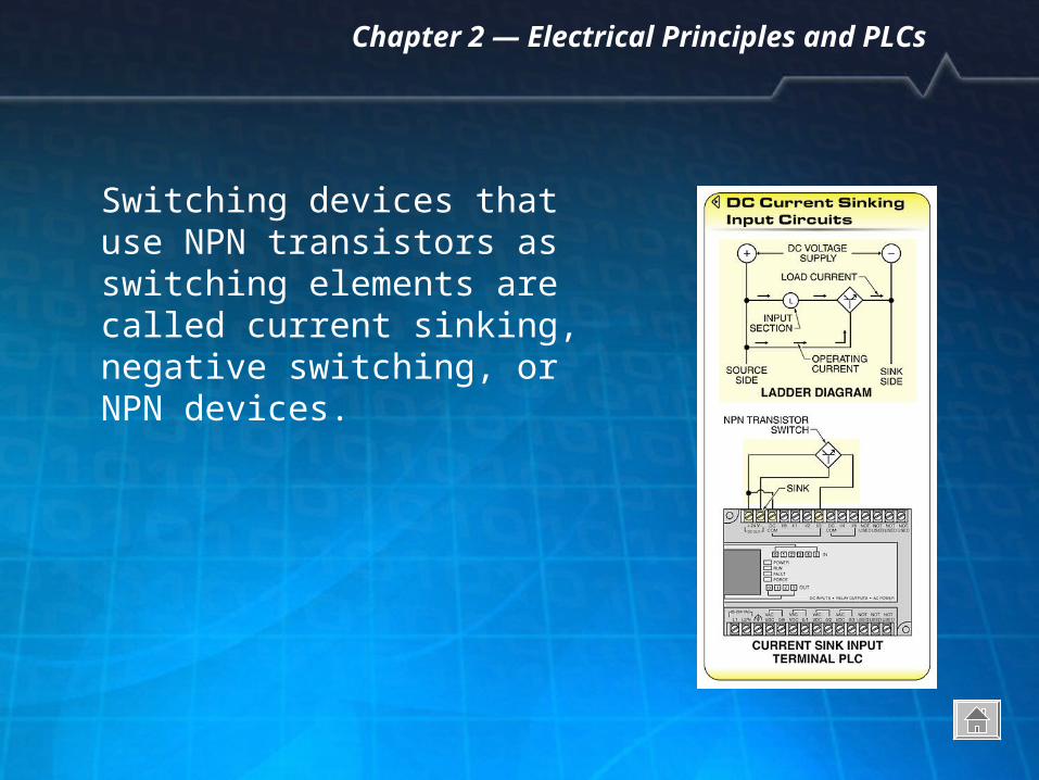
Switching devices that use NPN transistors as switching elements are called current sinking, negative switching, or NPN devices.
Chapter 2 — Electrical Principles and PLCs
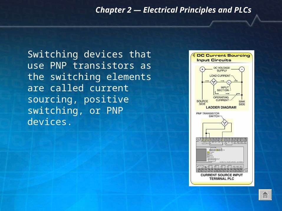
Switching devices that use PNP transistors as the switching elements are called current sourcing, positive switching, or PNP devices.
Chapter 2 — Electrical Principles and PLCs
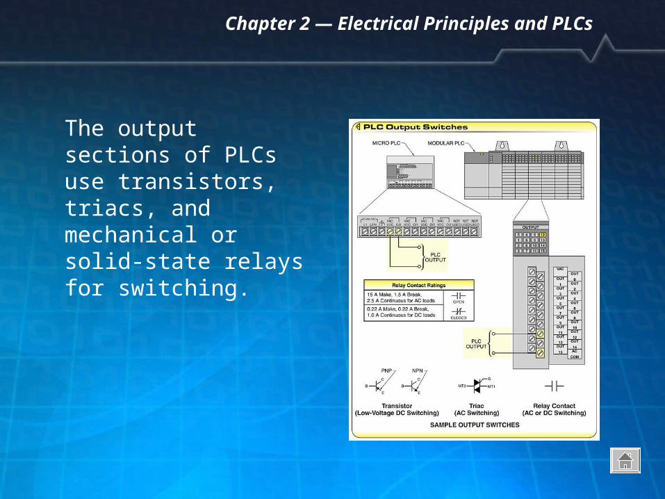
The output sections of PLCs use transistors, triacs, and mechanical or solid-state relays for switching.
Chapter 2 — Electrical Principles and PLCs
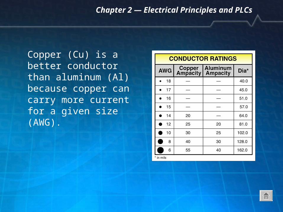
Copper (Cu) is a better conductor than aluminum (Al) because copper can carry more current for a given size (AWG).
Chapter 2 — Electrical Principles and PLCs
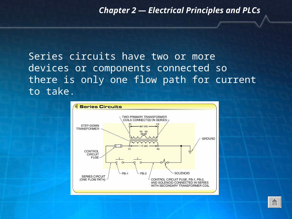
Series circuits have two or more devices or components connected so there is only one flow path for current to take.
Chapter 2 — Electrical Principles and PLCs
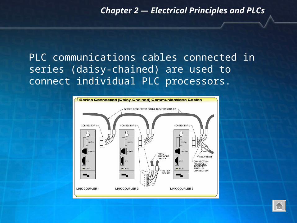
PLC communications cables connected in series (daisy-chained) are used to connect individual PLC processors.
Chapter 2 — Electrical Principles and PLCs
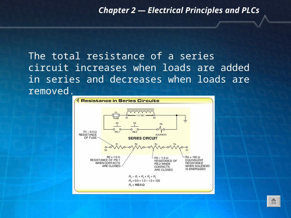
The total resistance of a series circuit increases when loads are added in series and decreases when loads are removed.
Chapter 2 — Electrical Principles and PLCs
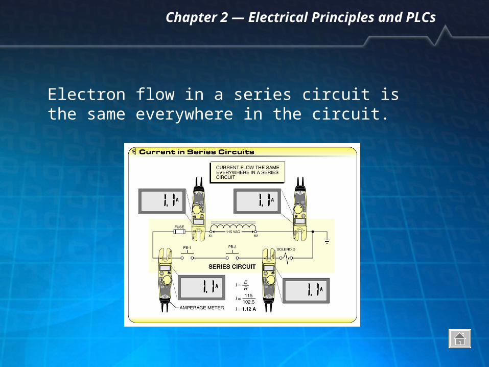
Electron flow in a series circuit is the same everywhere in the circuit.
Chapter 2 — Electrical Principles and PLCs
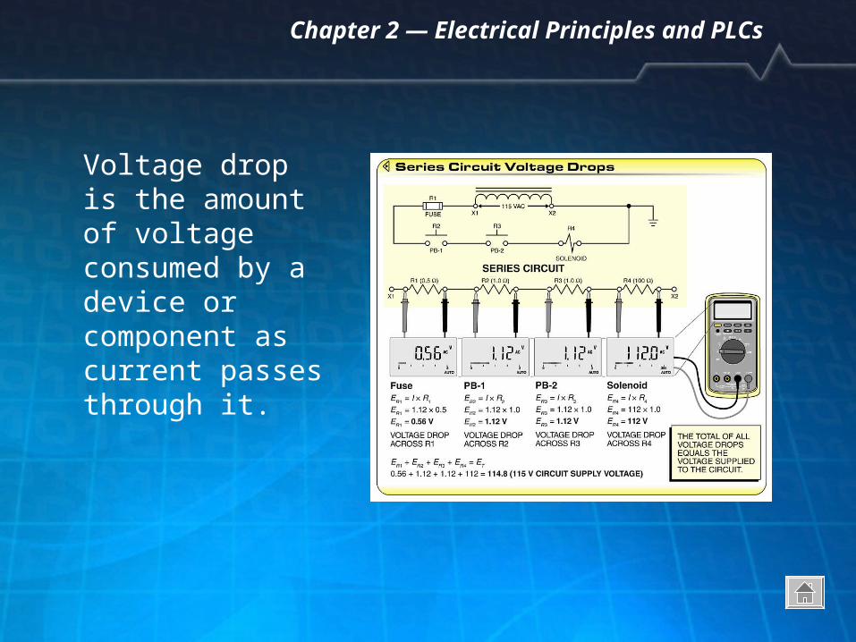
Voltage drop is the amount of voltage consumed by a device or component as current passes through it.
Chapter 2 — Electrical Principles and PLCs
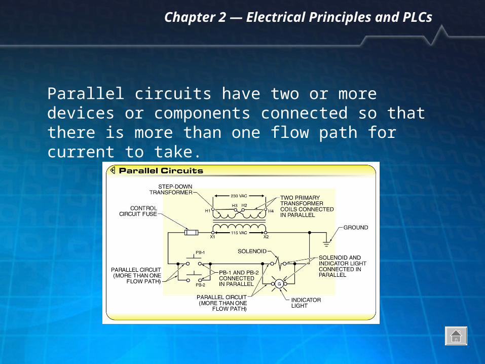
Parallel circuits have two or more devices or components connected so that there is more than one flow path for current to take.
Chapter 2 — Electrical Principles and PLCs
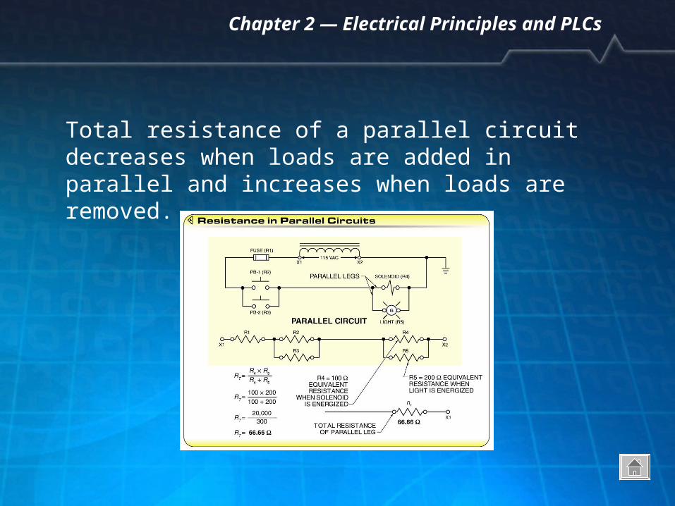
Total resistance of a parallel circuit decreases when loads are added in parallel and increases when loads are removed.
Chapter 2 — Electrical Principles and PLCs
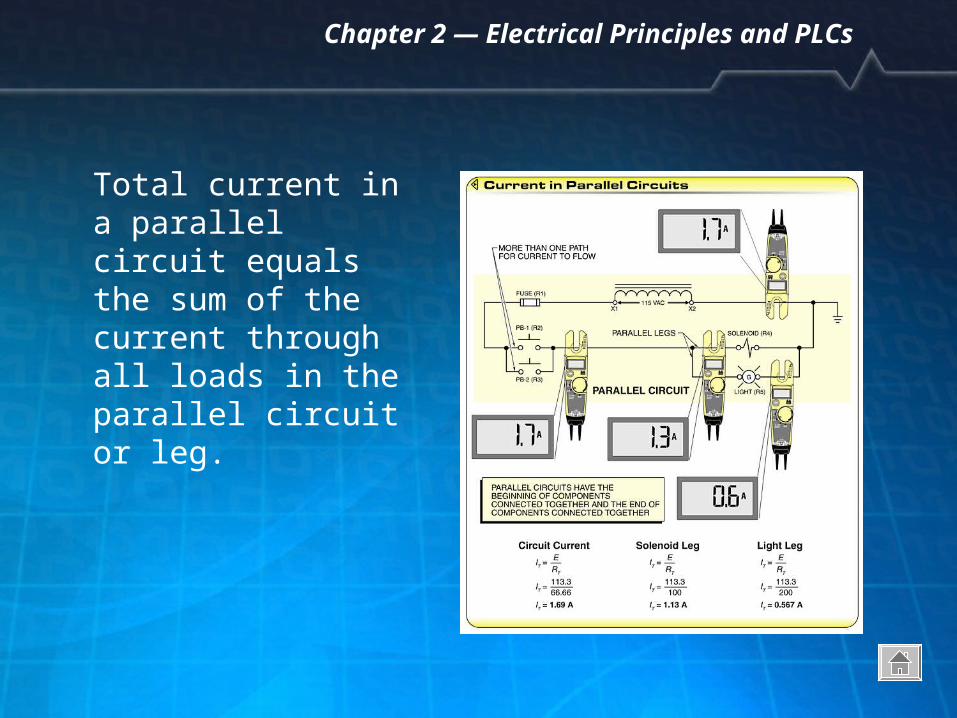
Total current in a parallel circuit equals the sum of the current through all loads in the parallel circuit or leg.
Chapter 2 — Electrical Principles and PLCs
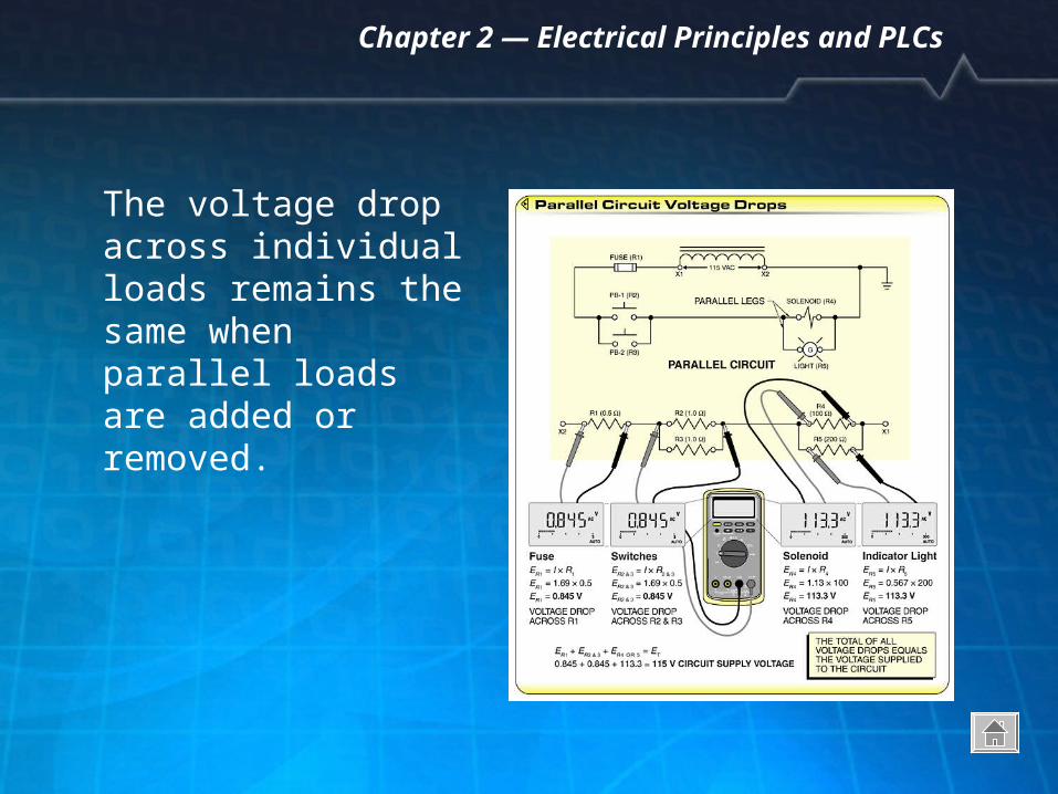
The voltage drop across individual loads remains the same when parallel loads are added or removed.