Embed Size (px)
Citation preview
Chapter 2Earthmoving Materials and
Operations
2-1 INTRODUCTION TO EARTHMOVING
• The Earthmoving Process• Equipment Selection• Production of Earthmoving Equipment
The Earthmoving Process
• Earthmoving is the process of moving soil or rock from one location to another and processing it so that it meets construction requirements of location, elevation, density, moisture content, and so on.
The Earthmoving Process
• Activities involved in this process include :– excavating, – loading, – hauling, – placing (dumping and spreading), – compacting, – grading, and – finishing.
The Earthmoving Process
• The construction procedures and equipment involved in earthmoving are described in Chapters 3 to 6.
• Efficient management of the earthmoving process requires :– accurate estimating of work quantities and job
conditions, – proper selection of equipment, and – competent job management.Production = Volume per cycle × Cycles per
hour (2-1)
Production of Earthmoving Equipment
• The cost per unit of production may be calculated as follows:
Cost per unit of production = Equipment cost per hour ÷ Equipment production per hour. (2-
2)
• Methods for determining the hourly cost of equipment operations are explained in Chapter 17.
Production of Earthmoving Equipment
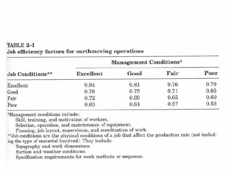
• There are two principal approaches to estimating job efficiency in determining the number of cycles per hour to be used in Equation 2-1. – One method is to use the number of effective
working minutes per hour to calculate the number of cycles achieved per hour. • This is equivalent to using an efficiency factor equal
to the number of working minutes per hour divided by 60.
2-2 EARTHMOVING MATERIALS
• General Soil Characteristics• Soil and Rock
General Soil Characteristics
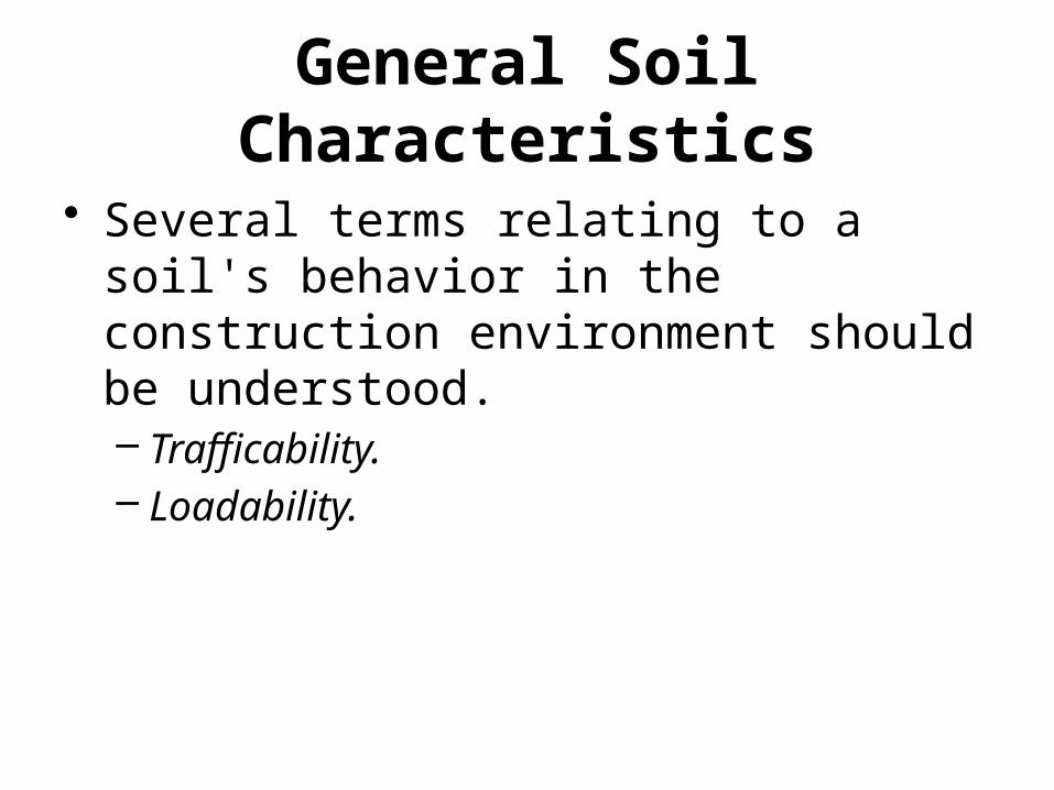
• Several terms relating to a soil's behavior in the construction environment should be understood.– Trafficability.– Loadability.
General Soil Characteristics
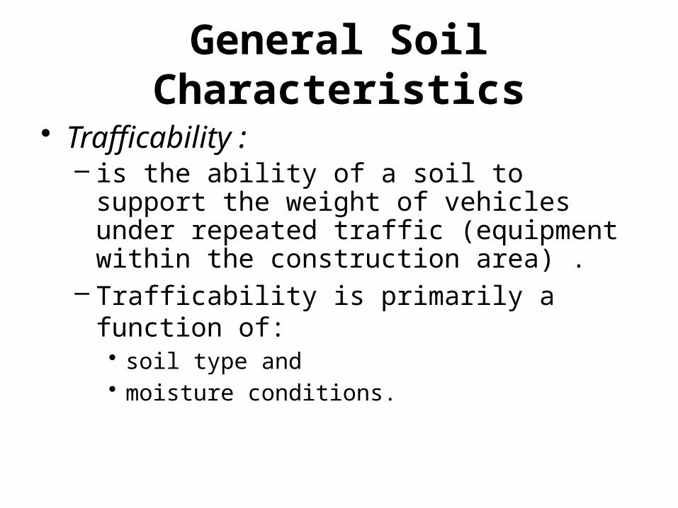
• Trafficability :– is the ability of a soil to support the weight of
vehicles under repeated traffic (equipment within the construction area) .
– Trafficability is primarily a function of:• soil type and • moisture conditions.
General Soil Characteristics
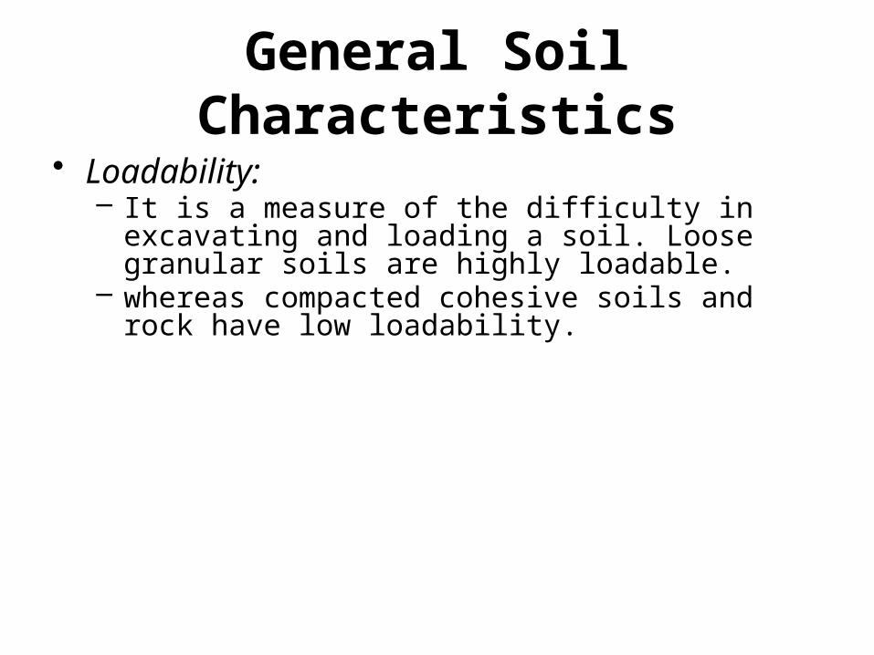
• Loadability:– It is a measure of the difficulty in excavating and
loading a soil. Loose granular soils are highly loadable.
– whereas compacted cohesive soils and rock have low loadability.
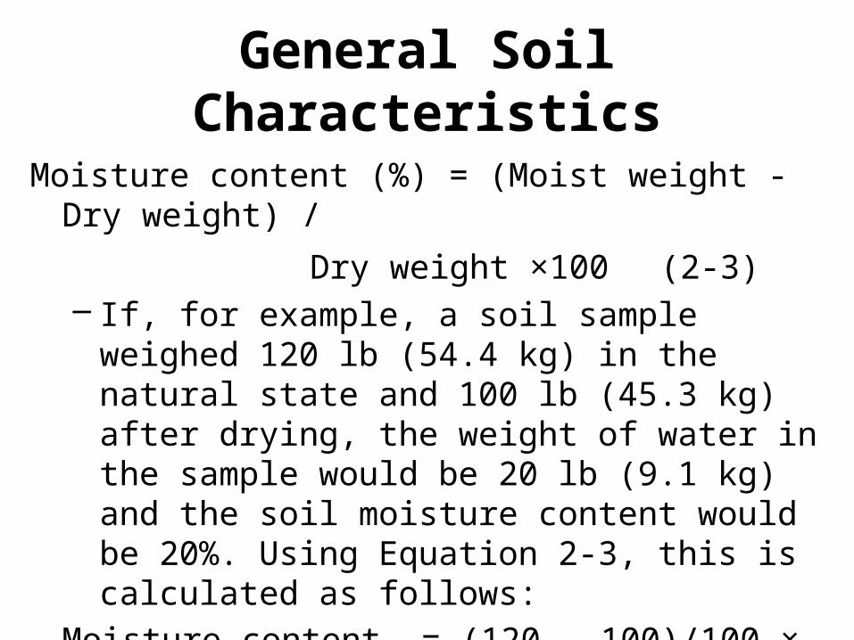
General Soil Characteristics
Moisture content (%) = (Moist weight - Dry weight) /
Dry weight ×100 (2-3)– If, for example, a soil sample weighed 120 lb
(54.4 kg) in the natural state and 100 lb (45.3 kg) after drying, the weight of water in the sample would be 20 lb (9.1 kg) and the soil moisture content would be 20%. Using Equation 2-3, this is calculated as follows:
Moisture content = (120 – 100)/100 × 100 = 20%
[= (54.4 - 45.3) / 45.3 × 100 = 20%]
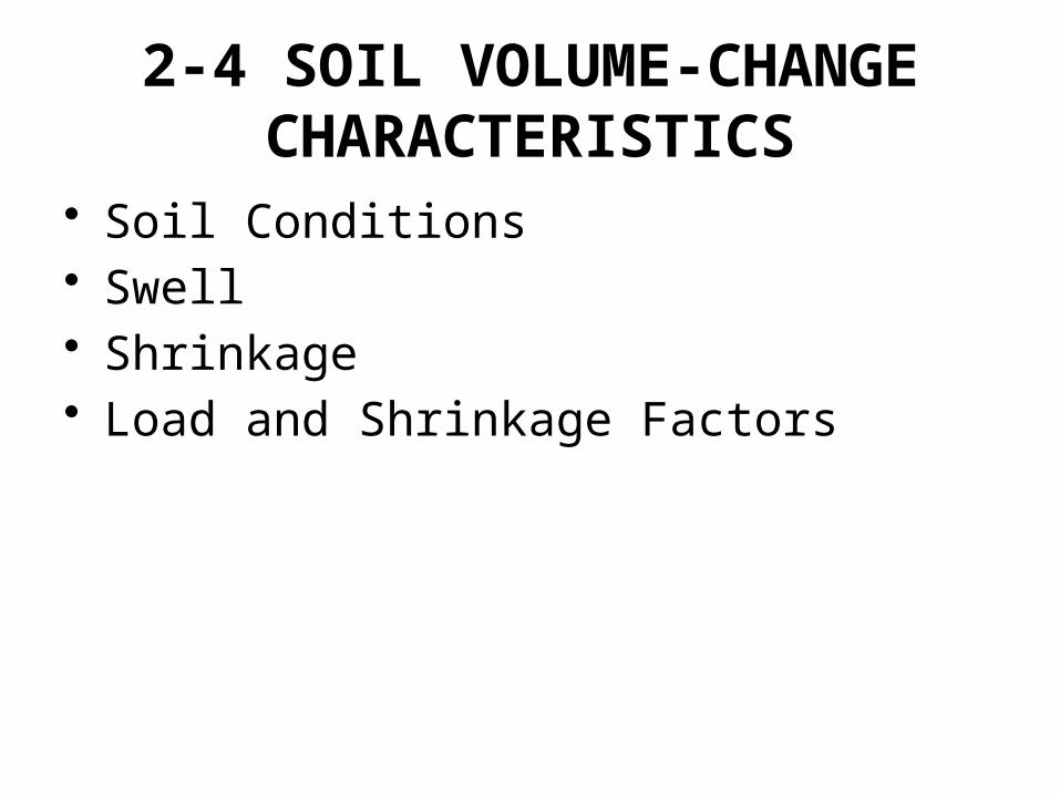
2-4 SOIL VOLUME-CHANGE CHARACTERISTICS
• Soil Conditions• Swell• Shrinkage• Load and Shrinkage Factors
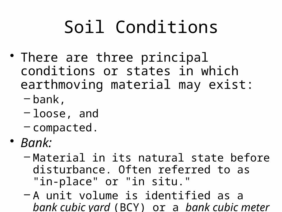
Soil Conditions
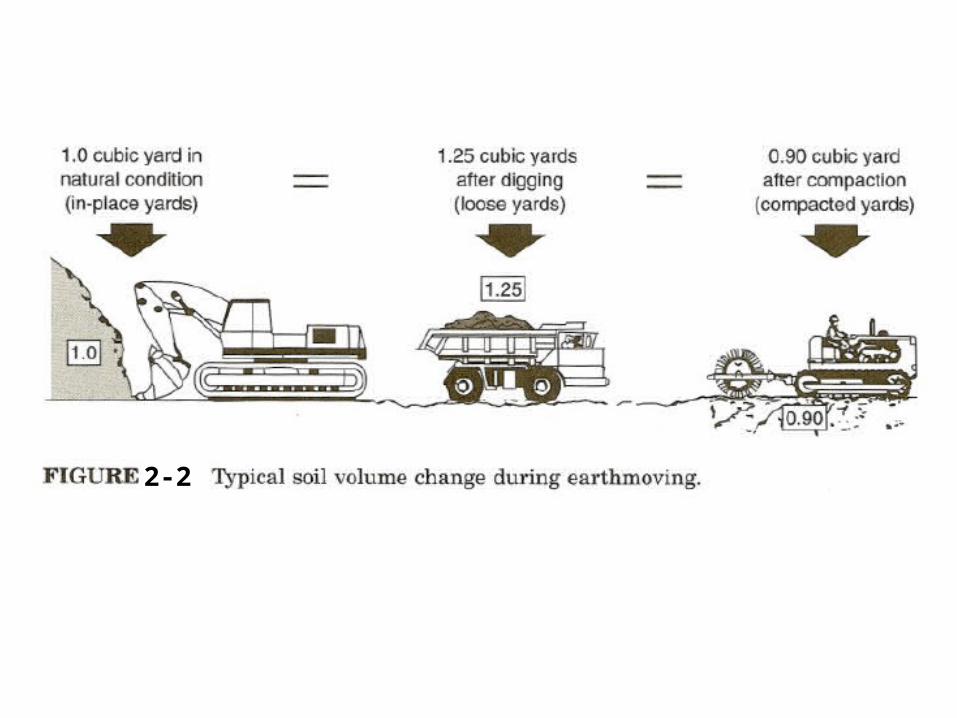
• There are three principal conditions or states in which earthmoving material may exist:– bank, – loose, and – compacted.
• Bank: – Material in its natural state before disturbance.
Often referred to as "in-place" or "in situ." – A unit volume is identified as a bank cubic yard
(BCY) or a bank cubic meter (BCM).
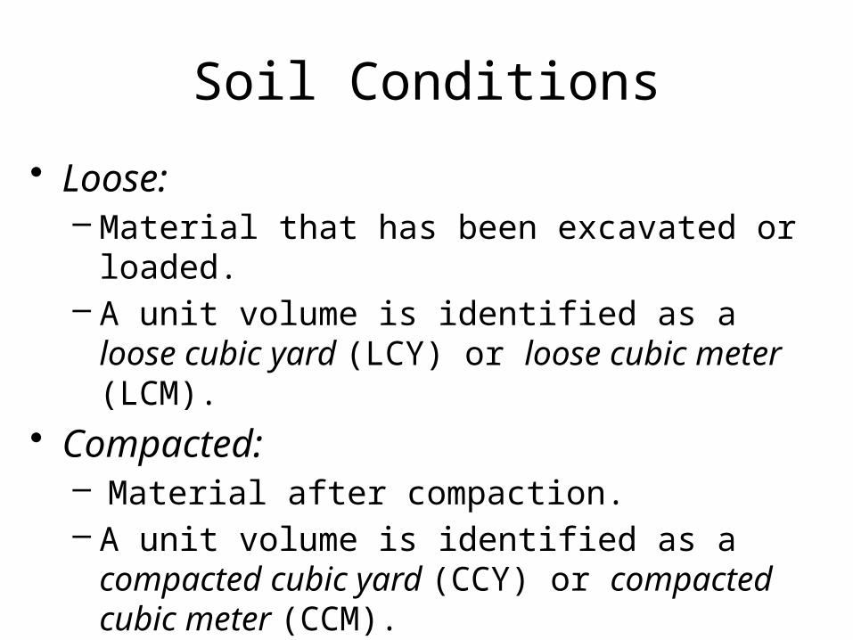
Soil Conditions
• Loose: – Material that has been excavated or loaded. – A unit volume is identified as a loose cubic yard
(LCY) or loose cubic meter (LCM).• Compacted:
– Material after compaction. – A unit volume is identified as a compacted cubic
yard (CCY) or compacted cubic meter (CCM).
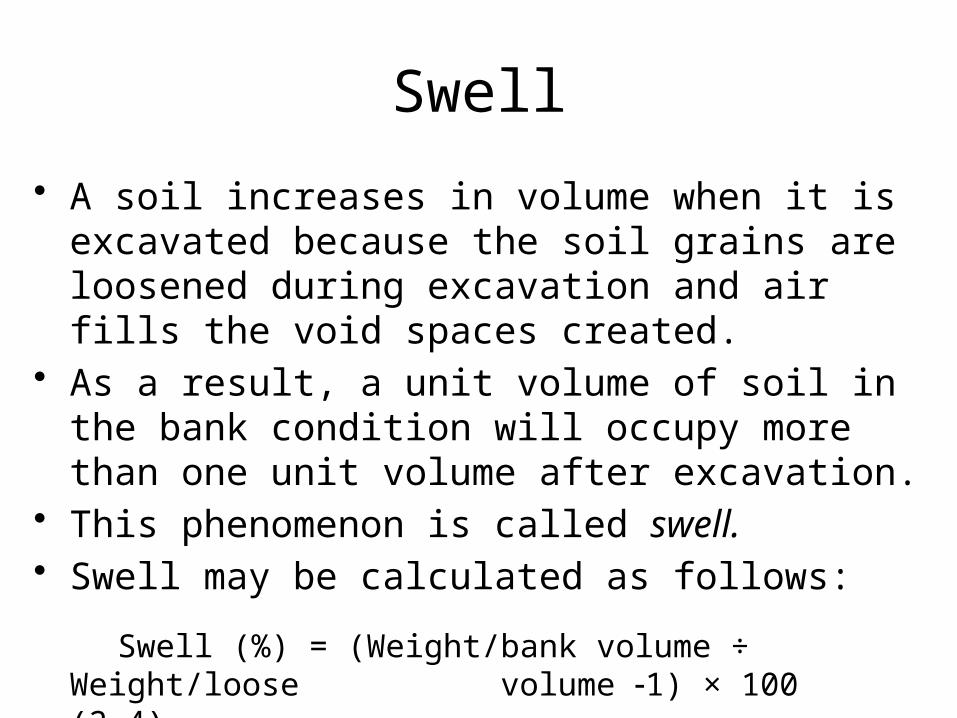
Swell
• A soil increases in volume when it is excavated because the soil grains are loosened during excavation and air fills the void spaces created.
• As a result, a unit volume of soil in the bank condition will occupy more than one unit volume after excavation.
• This phenomenon is called swell. • Swell may be calculated as follows:
Swell (%) = (Weight/bank volume ÷ Weight/loose volume 1) × 100 (2-4)
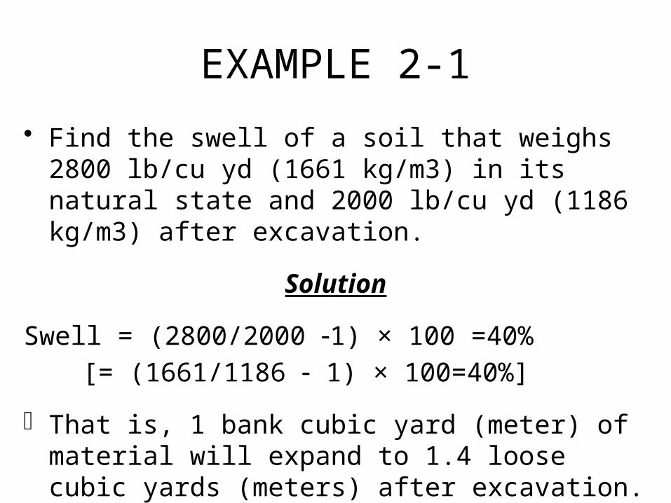
EXAMPLE 2-1
• Find the swell of a soil that weighs 2800 lb/cu yd (1661 kg/m3) in its natural state and 2000 lb/cu yd (1186 kg/m3) after excavation.
Solution
Swell = (2800/2000 1) × 100 =40%
[= (1661/1186 1) × 100=40%]
That is, 1 bank cubic yard (meter) of material will expand to 1.4 loose cubic yards (meters) after excavation.
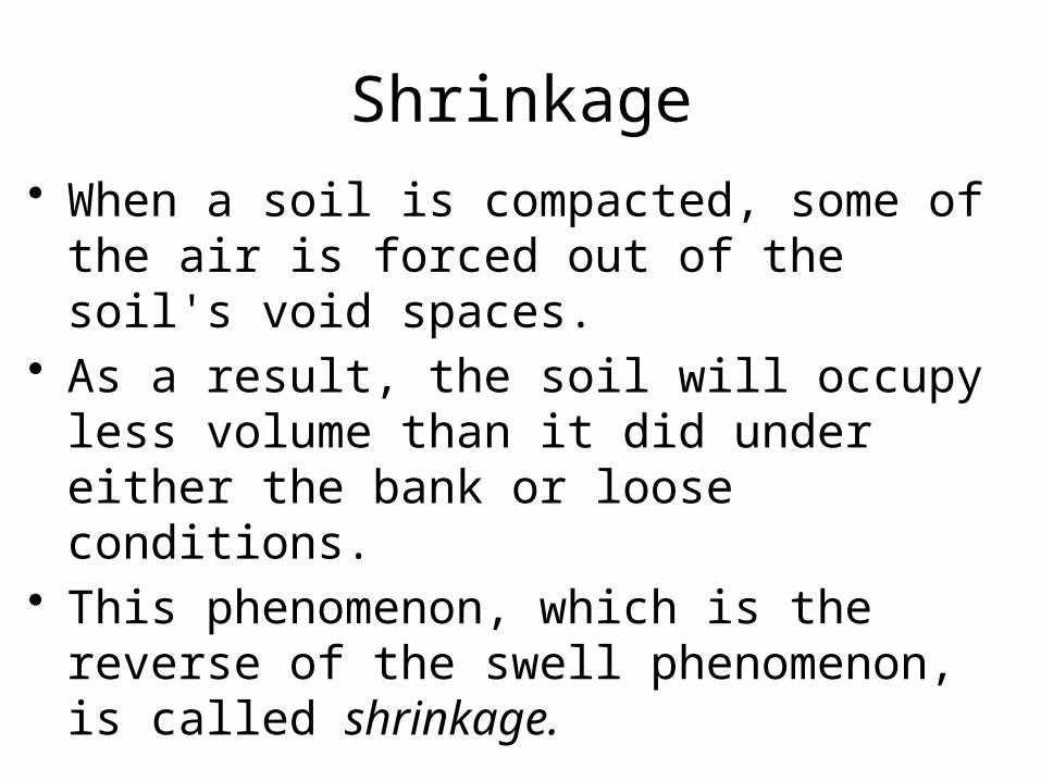
Shrinkage• When a soil is compacted, some of the air is
forced out of the soil's void spaces. • As a result, the soil will occupy less volume
than it did under either the bank or loose conditions.
• This phenomenon, which is the reverse of the swell phenomenon, is called shrinkage.
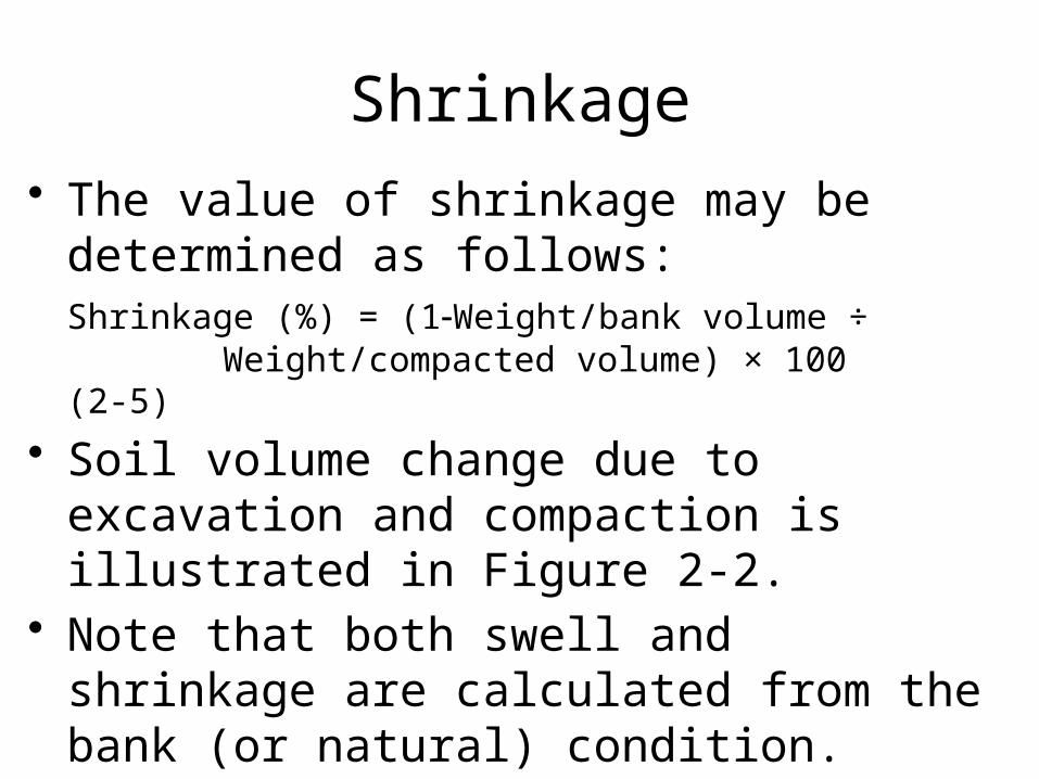
Shrinkage• The value of shrinkage may be determined
as follows:Shrinkage (%) = (1Weight/bank volume ÷
Weight/compacted volume) × 100 (2-5)
• Soil volume change due to excavation and compaction is illustrated in Figure 2-2.
• Note that both swell and shrinkage are calculated from the bank (or natural) condition.
2-2
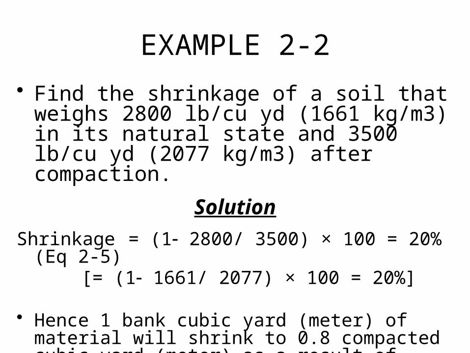
EXAMPLE 2-2
• Find the shrinkage of a soil that weighs 2800 lb/cu yd (1661 kg/m3) in its natural state and 3500 lb/cu yd (2077 kg/m3) after compaction.
Solution
Shrinkage = (1 2800/ 3500) × 100 = 20% (Eq 2-5)[= (1 1661/ 2077) × 100 = 20%]
• Hence 1 bank cubic yard (meter) of material will shrink to 0.8 compacted cubic yard (meter) as a result of compaction.
Load and Shrinkage Factors
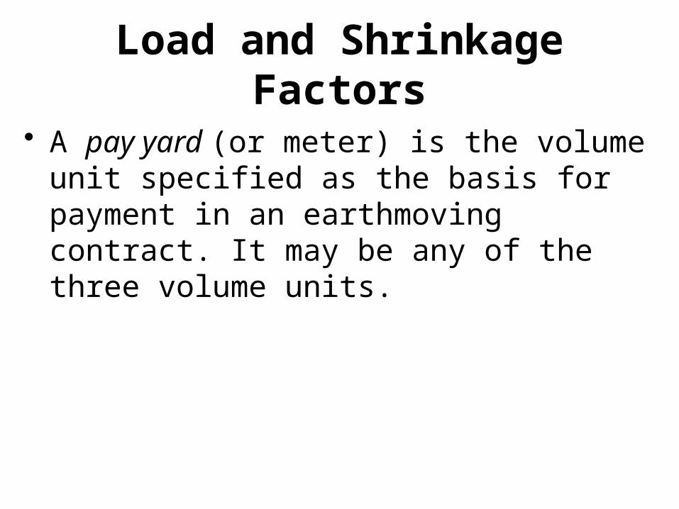
• A pay yard (or meter) is the volume unit specified as the basis for payment in an earthmoving contract. It may be any of the three volume units.
Load and Shrinkage Factors
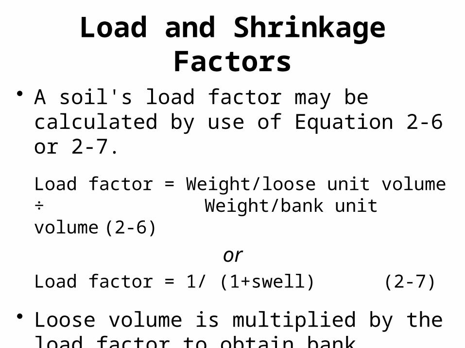
• A soil's load factor may be calculated by use of Equation 2-6 or 2-7.
Load factor = Weight/loose unit volume ÷ Weight/bank unit volume
(2-6)
orLoad factor = 1/ (1+swell) (2-7)
• Loose volume is multiplied by the load factor to obtain bank volume.
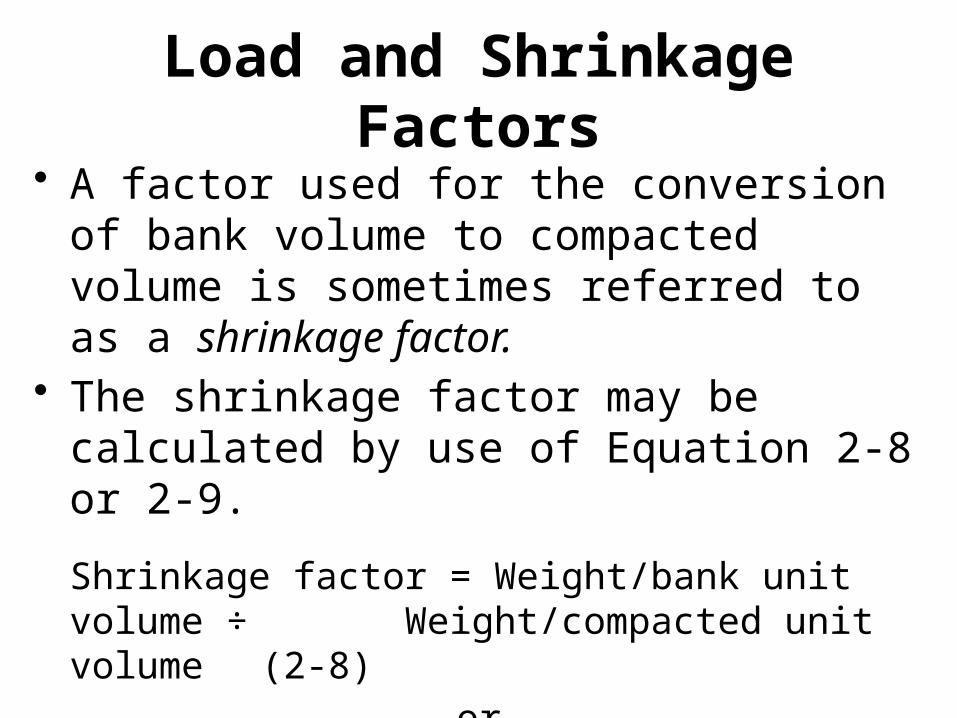
Load and Shrinkage Factors• A factor used for the conversion of bank
volume to compacted volume is sometimes referred to as a shrinkage factor.
• The shrinkage factor may be calculated by use of Equation 2-8 or 2-9.
Shrinkage factor = Weight/bank unit volume ÷ Weight/compacted unit volume (2-8)
or
Shrinkage factor = 1 shrinkage (2-9)
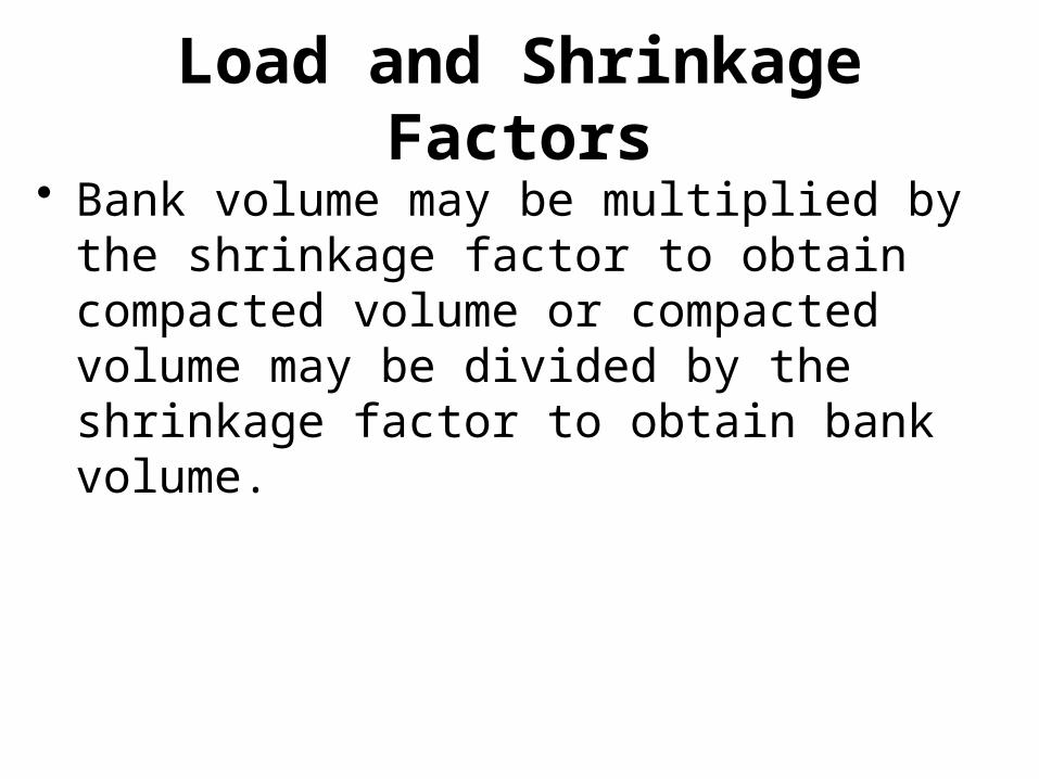
Load and Shrinkage Factors• Bank volume may be multiplied by the
shrinkage factor to obtain compacted volume or compacted volume may be divided by the shrinkage factor to obtain bank volume.
EXAMPLE 2-3
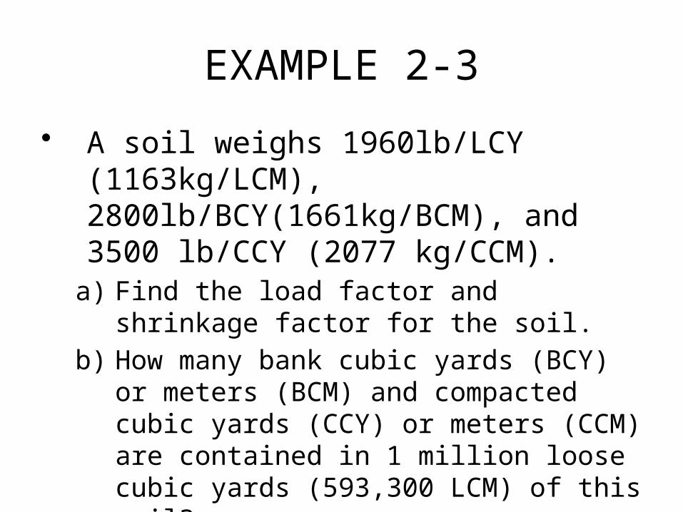
• A soil weighs 1960lb/LCY (1163kg/LCM), 2800lb/BCY(1661kg/BCM), and 3500 lb/CCY (2077 kg/CCM).
a) Find the load factor and shrinkage factor for the soil.
b) How many bank cubic yards (BCY) or meters (BCM) and compacted cubic yards (CCY) or meters (CCM) are contained in 1 million loose cubic yards (593,300 LCM) of this soil?
EXAMPLE 2-3
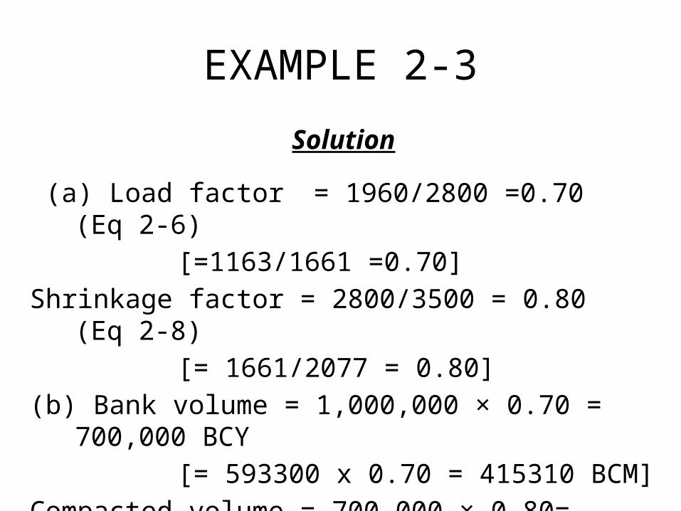
Solution
(a) Load factor = 1960/2800 =0.70 (Eq 2-6)
[=1163/1661 =0.70]
Shrinkage factor = 2800/3500 = 0.80 (Eq 2-8)
[= 1661/2077 = 0.80]
(b) Bank volume = 1,000,000 × 0.70 = 700,000 BCY
[= 593300 x 0.70 = 415310 BCM]
Compacted volume = 700,000 × 0.80= 560,000 CCY
[= 415310 × 0.80 = 332248 CCM]
Load and Shrinkage Factors
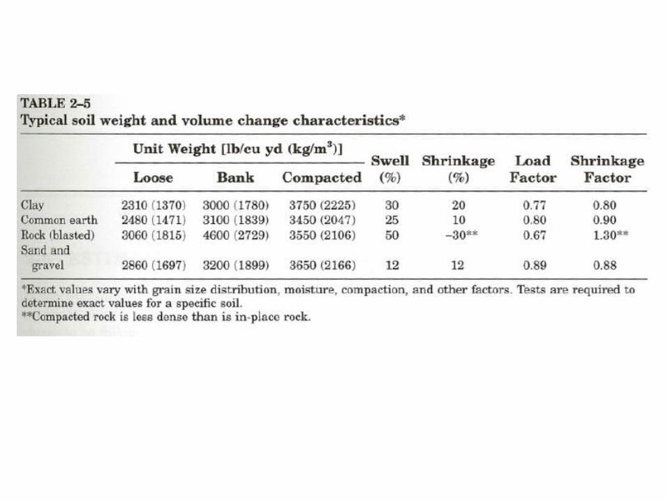
Typical values of unit weight, swell, shrinkage, load factor, and shrinkage factor for some common earthmoving materials are given in Table 2-5.
2-5 SPOIL BANKS
• When planning and estimating earthwork, it is frequently necessary to determine the size of the pile of material that will be created by the material removed from the excavation.
• If the pile of material is long in relation to its width, it is referred to as a spoil bank. Spoil banks are characterized by a triangular cross section.
2-5 SPOIL BANKS
• If the material is dumped from a fixed position, a spoil pile is created which has a conical shape.
• To determine the dimensions of spoil banks or piles, it is first necessary to convert the volume of excavation from in-place conditions (BCY or BCM) to loose conditions (LCY or LCM).
2-5 SPOIL BANKS
• Bank or pile dimensions may then be calculated using Equations 2-10 to 2-13 if the soil's angle of repose is known.
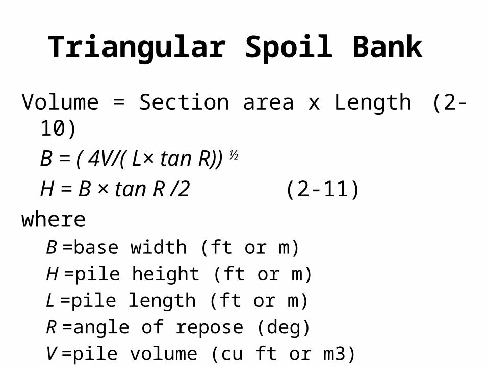
Triangular Spoil Bank
Volume = Section area x Length (2-10)
B = ( 4V/( L× tan R)) ½
H = B × tan R /2 (2-11)
where B =base width (ft or m)
H =pile height (ft or m)
L =pile length (ft or m)
R =angle of repose (deg)
V =pile volume (cu ft or m3)
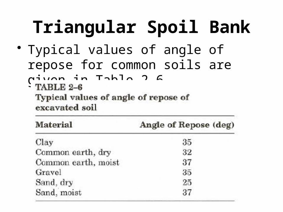
Triangular Spoil Bank• Typical values of angle of repose for
common soils are given in Table 2-6.
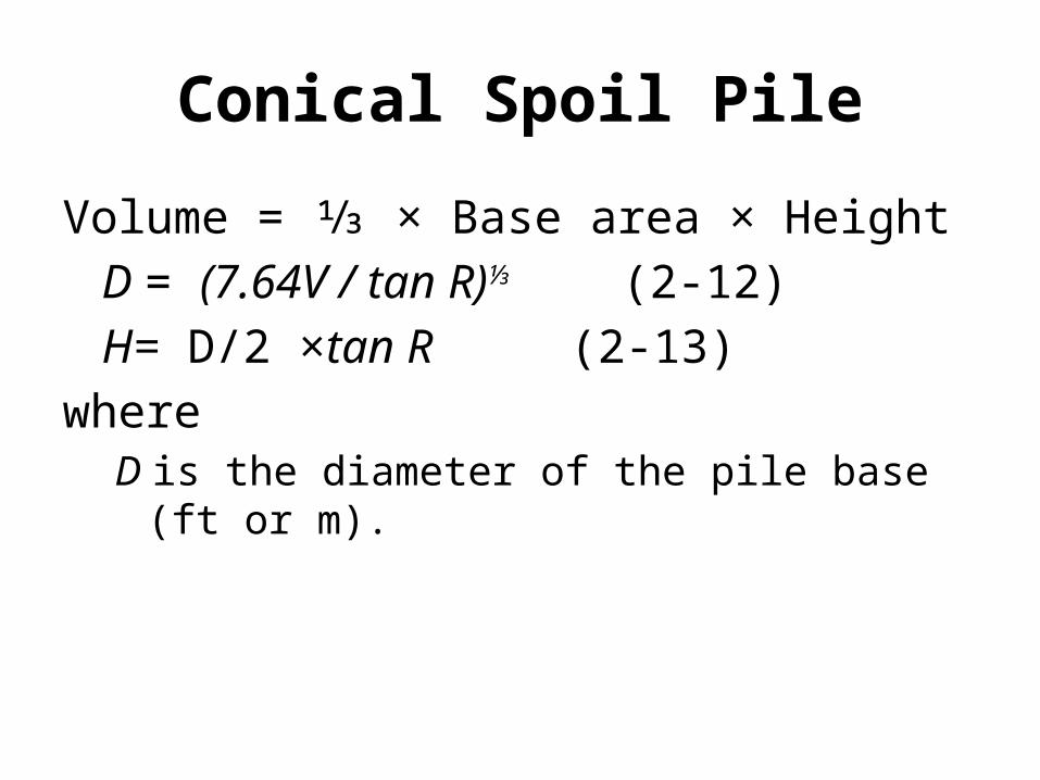
Conical Spoil Pile
Volume = ⅓ × Base area × Height
D = (7.64V / tan R)⅓ (2-12)
H= D/2 ×tan R (2-13)
where D is the diameter of the pile base (ft or m).
2-5 SPOIL BANKS
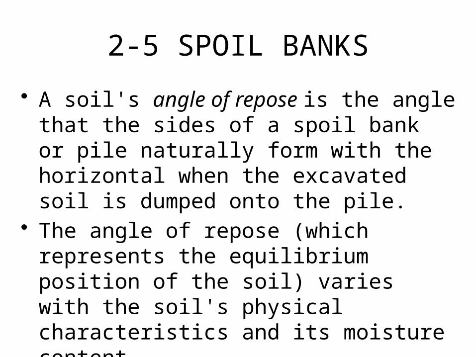
• A soil's angle of repose is the angle that the sides of a spoil bank or pile naturally form with the horizontal when the excavated soil is dumped onto the pile.
• The angle of repose (which represents the equilibrium position of the soil) varies with the soil's physical characteristics and its moisture content.
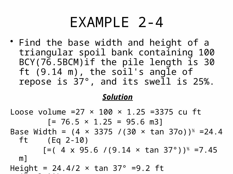
EXAMPLE 2-4• Find the base width and height of a triangular spoil
bank containing 100 BCY(76.5BCM)if the pile length is 30 ft (9.14 m), the soil's angle of repose is 37°, and its swell is 25%.
Solution
Loose volume =27 × 100 × 1.25 =3375 cu ft [= 76.5 × 1.25 = 95.6 m3]
Base Width = (4 × 3375 /(30 × tan 37o))½ =24.4 ft (Eq 2-10)[=( 4 x 95.6 /(9.14 × tan 37°))½ =7.45 m]
Height = 24.4/2 × tan 37° =9.2 ft (Eq 2-11)
[= 7.45/2 × tan 37° = 2.80 m]
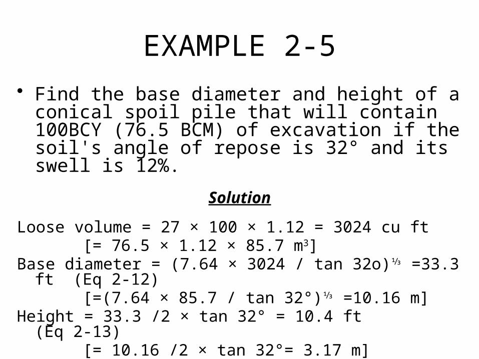
EXAMPLE 2-5
• Find the base diameter and height of a conical spoil pile that will contain 100BCY (76.5 BCM) of excavation if the soil's angle of repose is 32° and its swell is 12%.
Solution
Loose volume = 27 × 100 × 1.12 = 3024 cu ft[= 76.5 × 1.12 × 85.7 m3]
Base diameter = (7.64 × 3024 / tan 32o)⅓ =33.3 ft (Eq 2-12)[=(7.64 × 85.7 / tan 32°)⅓ =10.16 m]
Height = 33.3 /2 × tan 32° = 10.4 ft (Eq 2-13)[= 10.16 /2 × tan 32°= 3.17 m]
2-6 ESTIMATING EARTHWORK VOLUME
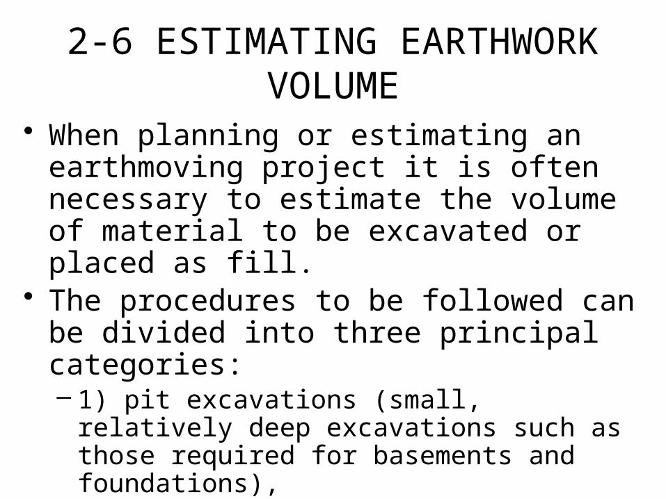
• When planning or estimating an earthmoving project it is often necessary to estimate the volume of material to be excavated or placed as fill.
• The procedures to be followed can be divided into three principal categories:– 1) pit excavations (small, relatively deep
excavations such as those required for basements and foundations),
– 2) trench excavation for utility lines, and – 3) excavating or grading relatively large areas.
2-6 ESTIMATING EARTHWORK VOLUME
• Procedures suggested for each of these three cases will now be described.– The estimation of the earthwork volume involved in the
construction of roads and airfields is customarily performed by the design engineer.
– The usual method is to calculate the cross-sectional area of cut or fill at regular intervals (such as stations [l00 ft or 33 m]) along the centerline.
– The volume of cut or fill between stations is then calculated, accumulated, and plotted as a mass diagram.
2-6 ESTIMATING EARTHWORK VOLUME
– While the construction of a mass diagram is beyond the scope of this book, some construction uses of the mass diagram are described in Section 2-7.
– When making earthwork volume calculations, keep in mind that cut volume is normally calculated in bank measure while the volume of compacted fill is calculated in compacted measure.
– Both cut and fill must be expressed in the same volume units before being added.
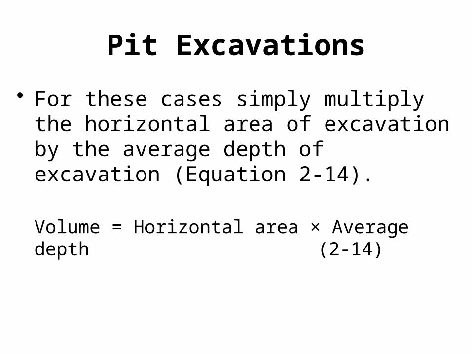
Pit Excavations
• For these cases simply multiply the horizontal area of excavation by the average depth of excavation (Equation 2-14).
Volume = Horizontal area × Average depth
(2-14)
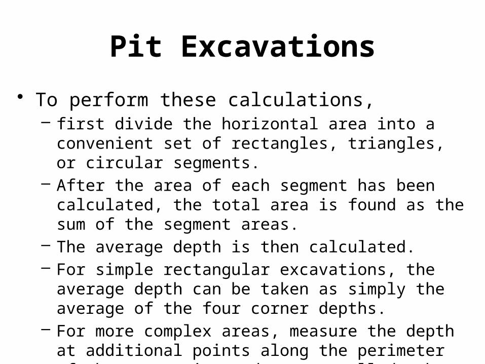
Pit Excavations
• To perform these calculations, – first divide the horizontal area into a convenient set of
rectangles, triangles, or circular segments. – After the area of each segment has been calculated, the
total area is found as the sum of the segment areas. – The average depth is then calculated. – For simple rectangular excavations, the average depth
can be taken as simply the average of the four corner depths.
– For more complex areas, measure the depth at additional points along the perimeter of the excavation and average all depths.
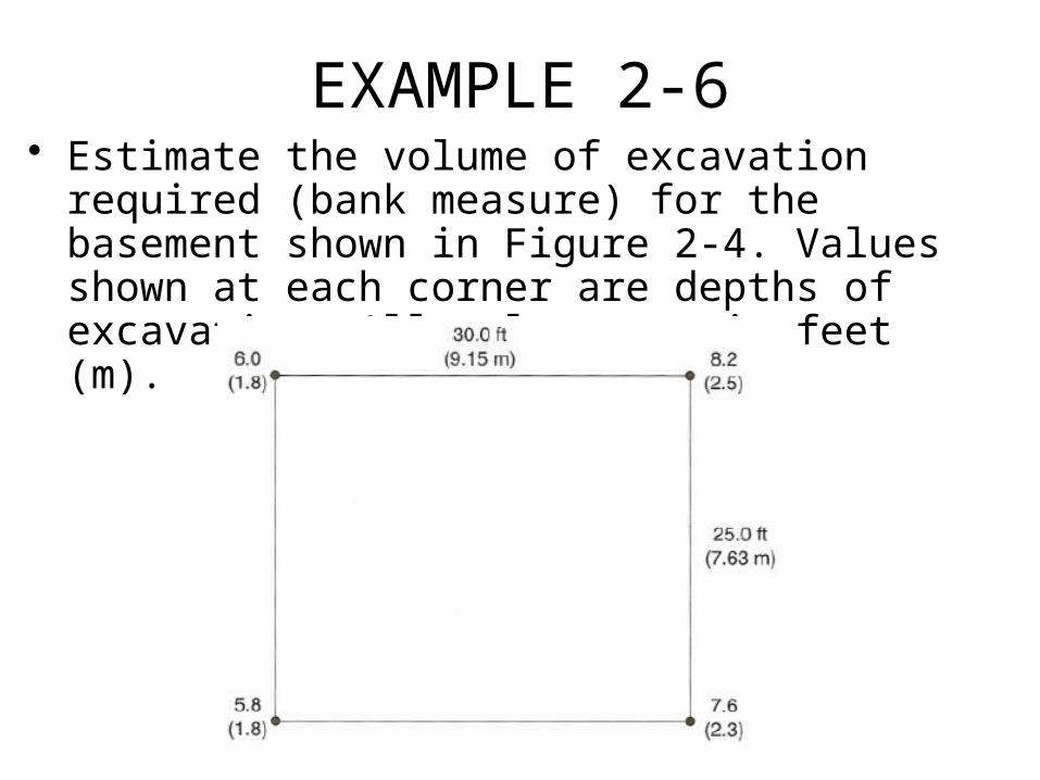
EXAMPLE 2-6• Estimate the volume of excavation required (bank
measure) for the basement shown in Figure 2-4. Values shown at each corner are depths of excavation. All values are in feet (m).
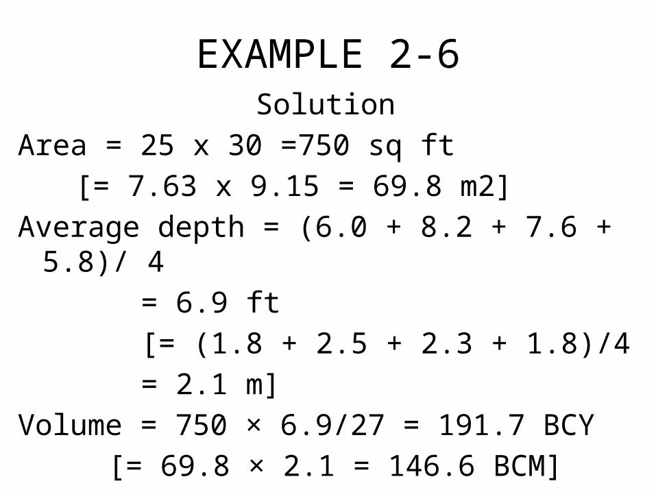
EXAMPLE 2-6Solution
Area = 25 x 30 =750 sq ft
[= 7.63 x 9.15 = 69.8 m2]
Average depth = (6.0 + 8.2 + 7.6 + 5.8)/ 4
= 6.9 ft
[= (1.8 + 2.5 + 2.3 + 1.8)/4
= 2.1 m]
Volume = 750 × 6.9/27 = 191.7 BCY
[= 69.8 × 2.1 = 146.6 BCM]
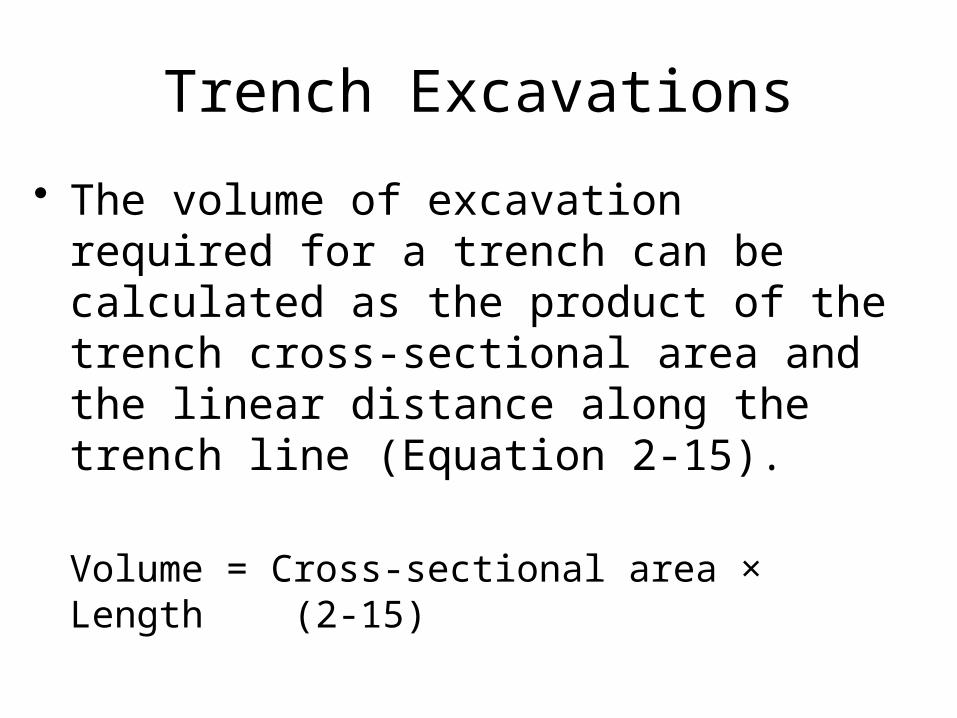
Trench Excavations
• The volume of excavation required for a trench can be calculated as the product of the trench cross-sectional area and the linear distance along the trench line (Equation 2-15).
Volume = Cross-sectional area × Length (2-15)
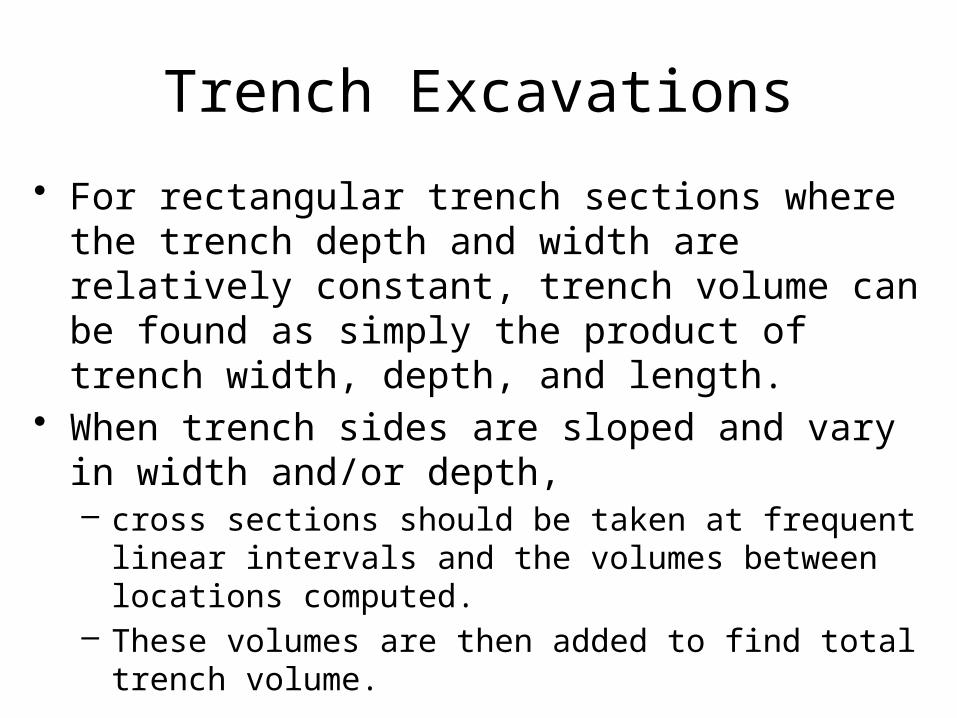
Trench Excavations
• For rectangular trench sections where the trench depth and width are relatively constant, trench volume can be found as simply the product of trench width, depth, and length.
• When trench sides are sloped and vary in width and/or depth, – cross sections should be taken at frequent linear intervals
and the volumes between locations computed. – These volumes are then added to find total trench
volume.
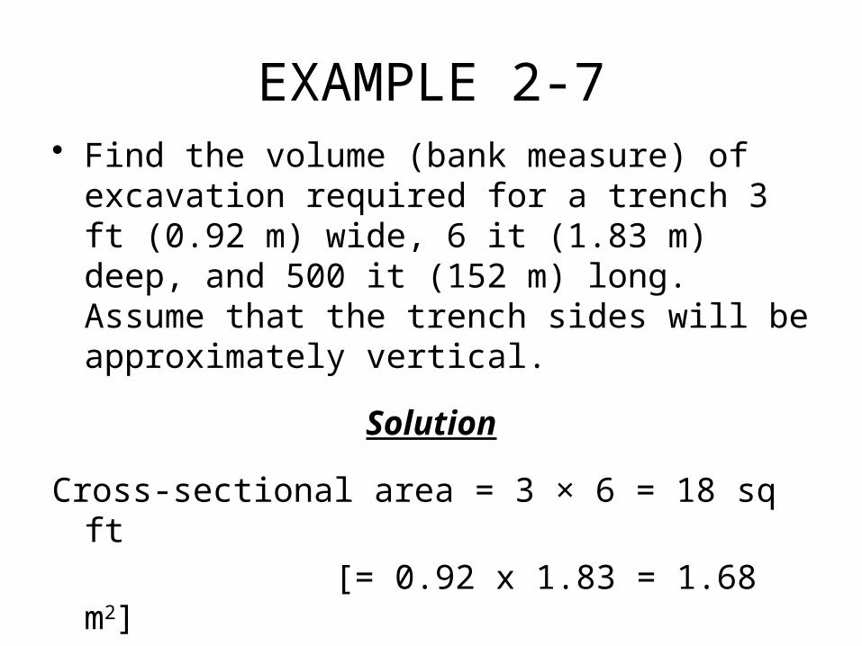
EXAMPLE 2-7• Find the volume (bank measure) of excavation
required for a trench 3 ft (0.92 m) wide, 6 it (1.83 m) deep, and 500 it (152 m) long. Assume that the trench sides will be approximately vertical.
Solution
Cross-sectional area = 3 × 6 = 18 sq ft
[= 0.92 x 1.83 = 1.68 m2]
Volume = 18 ×500/ 27 = 333 BCY
[= 1.68 × 152 = 255 BCM]
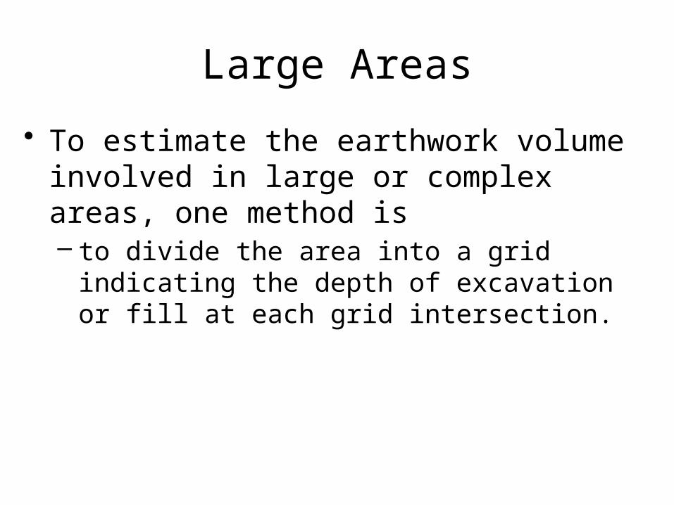
Large Areas
• To estimate the earthwork volume involved in large or complex areas, one method is– to divide the area into a grid indicating the depth
of excavation or fill at each grid intersection.
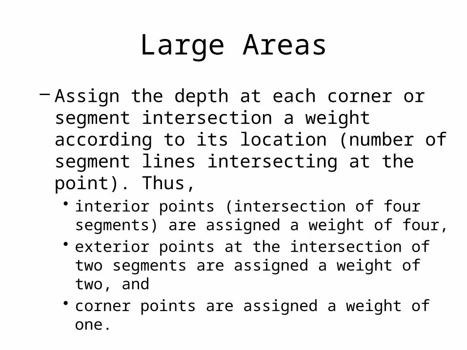
Large Areas
– Assign the depth at each corner or segment intersection a weight according to its location (number of segment lines intersecting at the point). Thus, • interior points (intersection of four segments) are
assigned a weight of four, • exterior points at the intersection of two segments are
assigned a weight of two, and • corner points are assigned a weight of one.
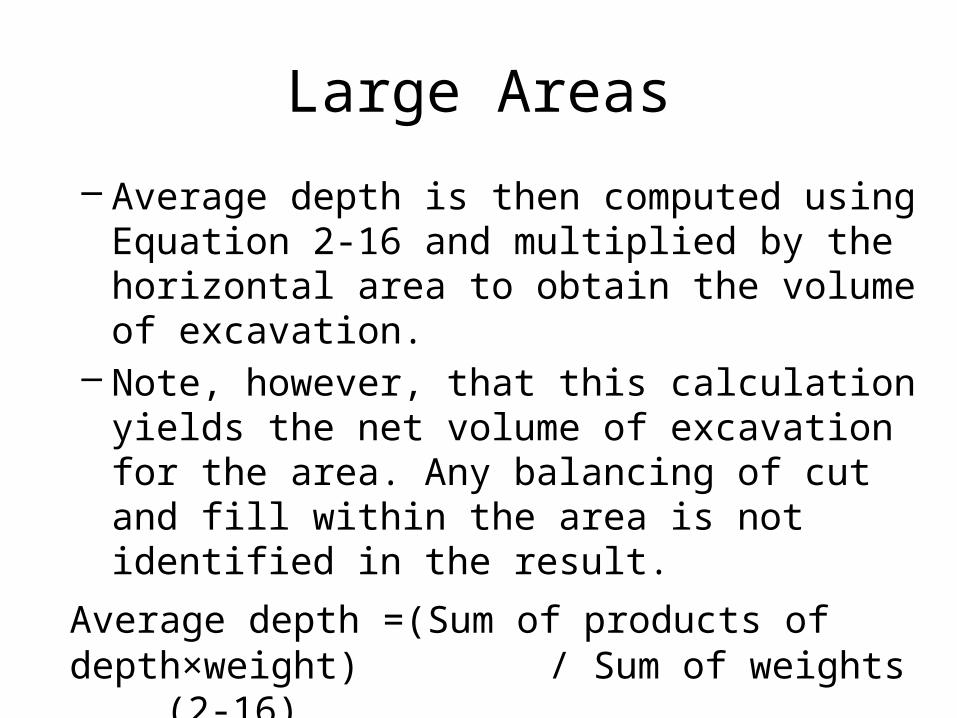
Large Areas
– Average depth is then computed using Equation 2-16 and multiplied by the horizontal area to obtain the volume of excavation.
– Note, however, that this calculation yields the net volume of excavation for the area. Any balancing of cut and fill within the area is not identified in the result.
Average depth =(Sum of products of depth×weight) / Sum of weights (2-
16)
EXAMPLE 2-8
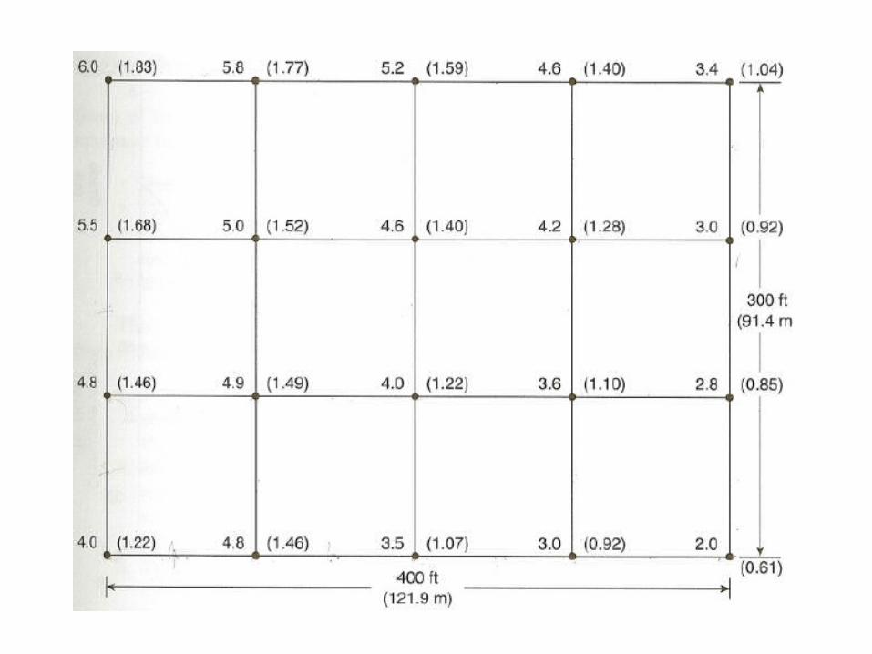
• Find the volume of excavation required for the area shown below. The figure at each grid intersection represents the depth of cut at that location. Depths in parentheses represent meters.
EXAMPLE 2-8
Solution
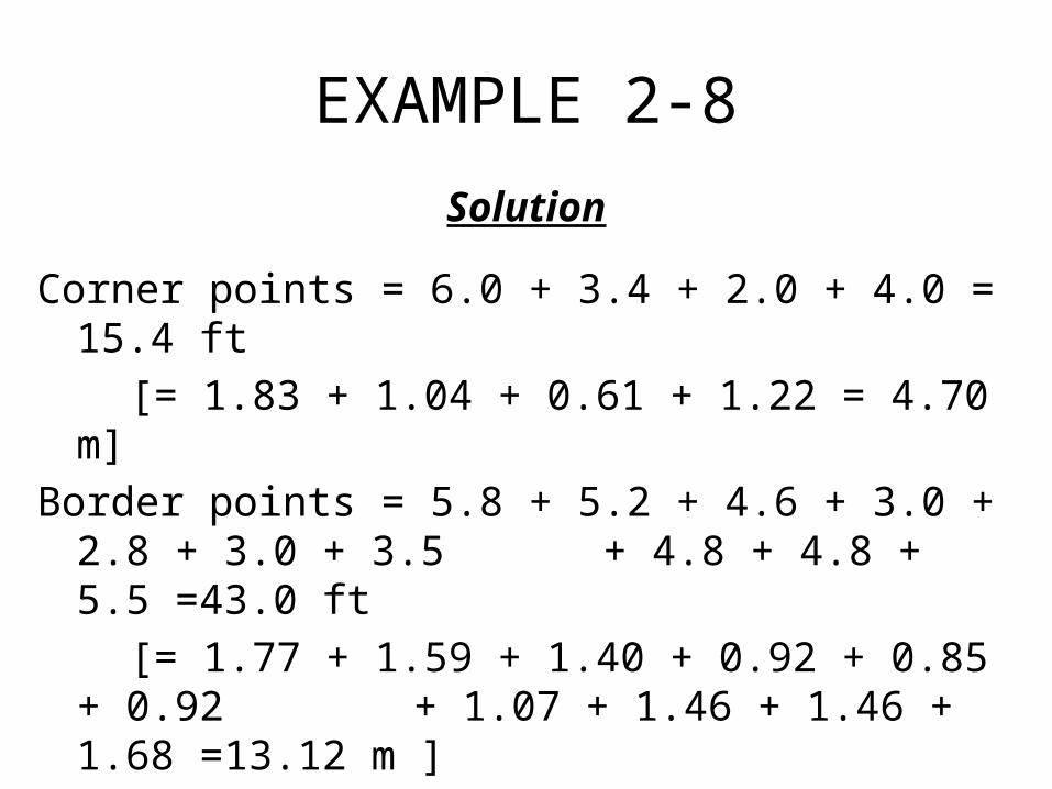
Corner points = 6.0 + 3.4 + 2.0 + 4.0 = 15.4 ft
[= 1.83 + 1.04 + 0.61 + 1.22 = 4.70 m]
Border points = 5.8 + 5.2 + 4.6 + 3.0 + 2.8 + 3.0 + 3.5 + 4.8 + 4.8 + 5.5 =43.0 ft
[= 1.77 + 1.59 + 1.40 + 0.92 + 0.85 + 0.92 + 1.07 + 1.46 + 1.46 + 1.68 =13.12
m ]
Interior points = 5.0 +4.6 +4.2 +4.9 +4.0 +3.6 = 26.3 ft
[= 1.52+ 1.40+ 1.28+ 1.49+ 1.22+ 1.10=8.01 m]

EXAMPLE 2-8
Average depth = {15.4 + 2(43.0) + 4(26.3)}/48 = 3.97 ft
[= {4.70 + 2(13.12) +4(8.01)}/48 = 1.21 m]
Area =300 × 400 = 120,000 sq ft
[= 91.4 × 121.9 = 11,142 m2]
Volume= 120,000 × 3.97/27 = 17,689 BCY
[= 11,142 x 1.21 = 13,482 BCM]
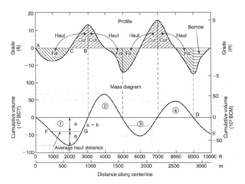
2-7 CONSTRUCTION USE OF THE MASS DIAGRAM
• A mass diagram is a continuous curve representing the accumulated volume of earthwork plotted against the linear profile of a roadway or airfield.
• Mass diagrams are prepared by highway and airfield designers to assist in selecting an alignment which minimizes the earthwork required to construct the facility while meeting established limits of roadway grade and curvature.
Characteristics of a Mass Diagram
• Some of the principal characteristics of a mass diagram include the following.– The vertical coordinate of the mass diagram
corresponding to any location on the roadway profile represents the cumulative earthwork
– volume from the origin to that point. – Within a cut, the curve rises from left to right.
Characteristics of a Mass Diagram
– Within a fill, the curve falls from left to right. A peak on the curve represents a point where the earthwork changes from cut to fill.
– A valley (low point) on the curve represents a point where the earthwork changes from fill to cut.
– When a horizontal line intersects the curve at two or more points, the accumulated volumes at these points are equal. Thus, such a line represents a balance line on the diagram.
Using the Mass Diagram
• Some of the information which a mass diagram can provide a construction manager includes the following.– The length and direction of haul within a balanced
section.– The average length of haul for a balanced section.– The location and amount of borrow (material hauled in
from a borrow pit) and waste (material hauled away to a waste area) for the project.
Using the Mass Diagram
• The following explanation of methods for obtaining this information from a mass diagram will be illustrated using Figure 2-5.1. For a balanced section (section 1 on the figure), project
the end points of the section up to the profile (points A and B). These points identify the limits of the balanced section.
2. Locate point C on the profile corresponding to the lowest point of the mass diagram within section 1. This is the point at which the excavation changes from fill to cut. The areas of cut and fill can now be identified on the profile.
3. The direction of haul within a balanced section is always from cut to fill.
Using the Mass Diagram
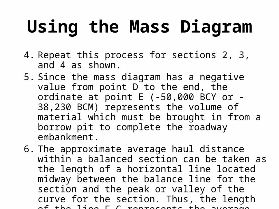
4. Repeat this process for sections 2, 3, and 4 as shown.5. Since the mass diagram has a negative value from
point D to the end, the ordinate at point E (-50,000 BCY or -38,230 BCM) represents the volume of material which must be brought in from a borrow pit to complete the roadway embankment.
6. The approximate average haul distance within a balanced section can be taken as the length of a horizontal line located midway between the balance line for the section and the peak or valley of the curve for the section. Thus, the length of the line F-G represents the average haul distance for section 1, which is 1800 ft or 549 m.