Embed Size (px)
Citation preview
CHAPTER 2:DESIGN OF DIC MEASUREMENTS
SEC. 2.1:MEASUREMENT REQUIREMENTS
SAND2020-9051 TR (slides)SAND2020-9046 TR (videos)
2
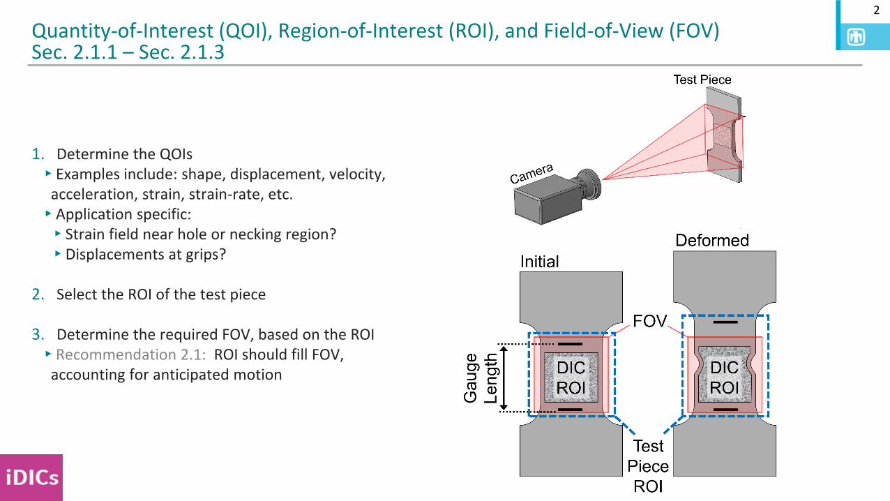
Quantity-of-Interest (QOI), Region-of-Interest (ROI), and Field-of-View (FOV)Sec. 2.1.1 – Sec. 2.1.3
1. Determine the QOIs▸Examples include: shape, displacement, velocity,
acceleration, strain, strain-rate, etc.▸Application specific:▸Strain field near hole or necking region?▸Displacements at grips?
2. Select the ROI of the test piece
3. Determine the required FOV, based on the ROI▸Recommendation 2.1: ROI should fill FOV,
accounting for anticipated motion
3
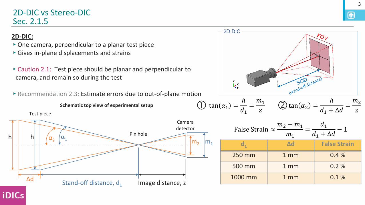
2D-DIC: ▸One camera, perpendicular to a planar test piece▸Gives in-plane displacements and strains
▸Caution 2.1: Test piece should be planar and perpendicular to camera, and remain so during the test
▸Recommendation 2.3: Estimate errors due to out-of-plane motion
2D-DIC vs Stereo-DICSec. 2.1.5
False Strain ≈𝑚2 −𝑚1
𝑚1=
𝑑1𝑑1 + ∆𝑑
− 1
Schematic top view of experimental setup
Test piece
Pin hole
Cameradetector
α1α2h h
Stand-off distance, d1∆d
m2 m1
Image distance, z
tan 𝛼1 =ℎ
𝑑1=𝑚1
𝑧 tan 𝛼2 =ℎ
𝑑1 + Δ𝑑=𝑚2
𝑧
d1 Δd False Strain
250 mm 1 mm 0.4 %
500 mm 1 mm 0.2 %
1000 mm 1 mm 0.1 %
4
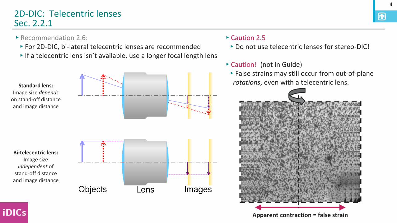
▸Recommendation 2.6:▸For 2D-DIC, bi-lateral telecentric lenses are recommended▸If a telecentric lens isn’t available, use a longer focal length lens
2D-DIC: Telecentric lensesSec. 2.2.1
▸Caution 2.5▸Do not use telecentric lenses for stereo-DIC!
▸Caution! (not in Guide)▸False strains may still occur from out-of-plane
rotations, even with a telecentric lens.
Apparent contraction = false strain
Standard lens: Image size depends
on stand-off distance and image distance
Bi-telecentric lens: Image size
independent of stand-off distance
and image distance
5
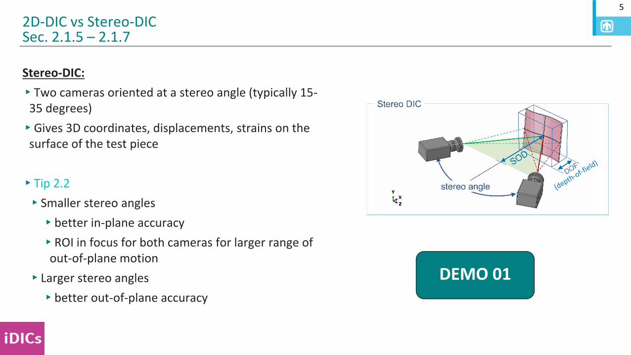
Stereo-DIC:
▸Two cameras oriented at a stereo angle (typically 15-35 degrees)
▸Gives 3D coordinates, displacements, strains on the surface of the test piece
▸Tip 2.2
▸Smaller stereo angles
▸better in-plane accuracy
▸ROI in focus for both cameras for larger range of out-of-plane motion
▸Larger stereo angles
▸better out-of-plane accuracy
2D-DIC vs Stereo-DICSec. 2.1.5 – 2.1.7
DEMO 01
6
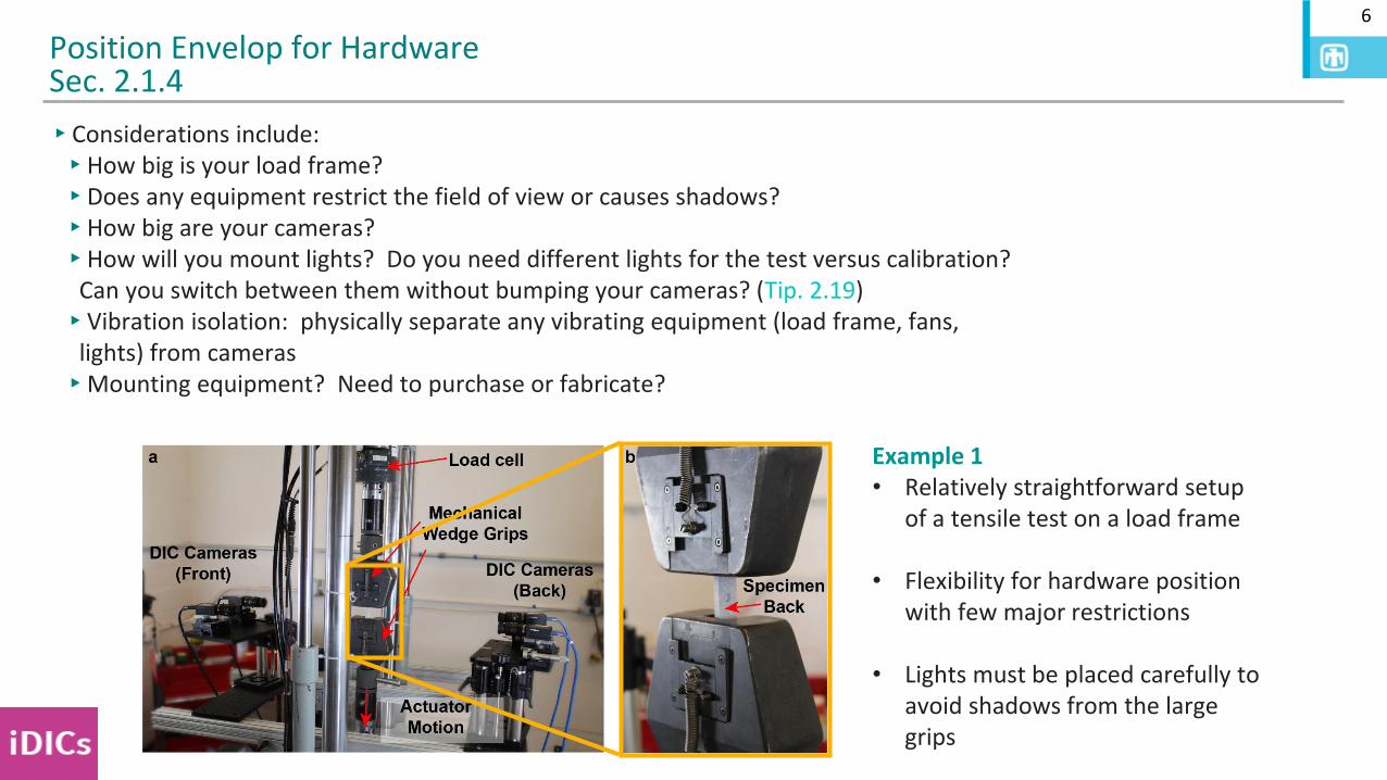
▸Considerations include:▸How big is your load frame?▸Does any equipment restrict the field of view or causes shadows?▸How big are your cameras? ▸How will you mount lights? Do you need different lights for the test versus calibration?
Can you switch between them without bumping your cameras? (Tip. 2.19)▸Vibration isolation: physically separate any vibrating equipment (load frame, fans,
lights) from cameras▸Mounting equipment? Need to purchase or fabricate?
Position Envelop for HardwareSec. 2.1.4
Example 1• Relatively straightforward setup
of a tensile test on a load frame
• Flexibility for hardware position with few major restrictions
• Lights must be placed carefully to avoid shadows from the large grips
7
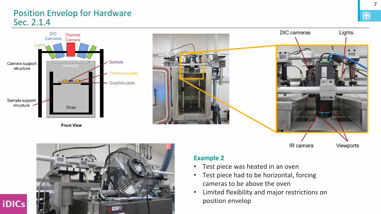
Position Envelop for HardwareSec. 2.1.4
Example 2• Test piece was heated in an oven• Test piece had to be horizontal, forcing
cameras to be above the oven• Limited flexibility and major restrictions on
position envelop
8
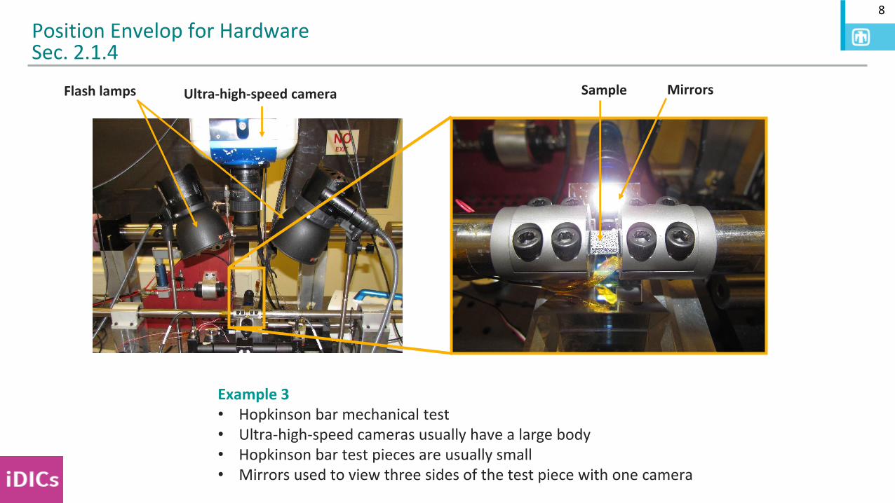
Position Envelop for HardwareSec. 2.1.4
Example 3• Hopkinson bar mechanical test• Ultra-high-speed cameras usually have a large body• Hopkinson bar test pieces are usually small• Mirrors used to view three sides of the test piece with one camera
Ultra-high-speed cameraFlash lamps Sample Mirrors
9
Position Envelop for HardwareSec. 2.1.4
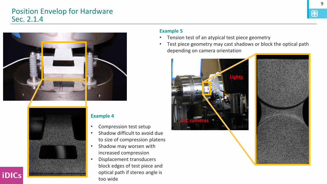
Example 4
• Compression test setup• Shadow difficult to avoid due
to size of compression platens• Shadow may worsen with
increased compression• Displacement transducers
block edges of test piece and optical path if stereo angle is too wide
Example 5• Tension test of an atypical test piece geometry• Test piece geometry may cast shadows or block the optical path
depending on camera orientation
DIC cameras
Lights
10
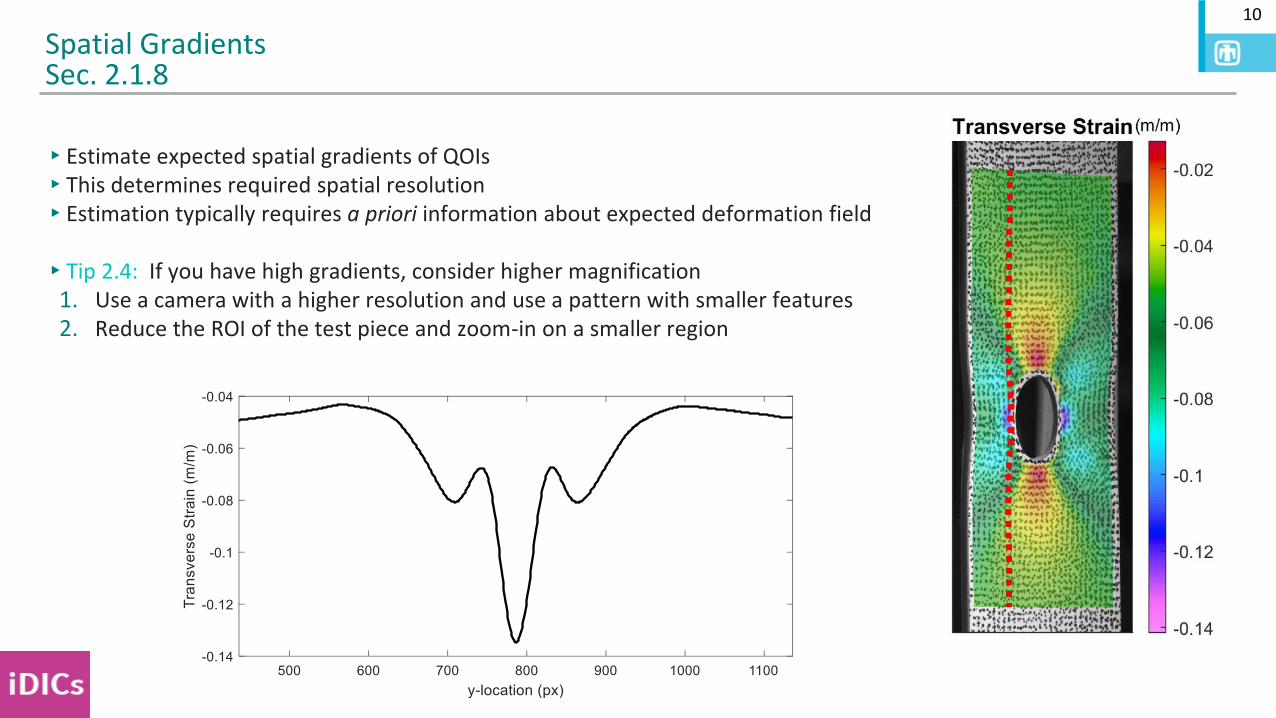
▸Estimate expected spatial gradients of QOIs ▸This determines required spatial resolution▸Estimation typically requires a priori information about expected deformation field
▸Tip 2.4: If you have high gradients, consider higher magnification1. Use a camera with a higher resolution and use a pattern with smaller features2. Reduce the ROI of the test piece and zoom-in on a smaller region
Spatial GradientsSec. 2.1.8
11
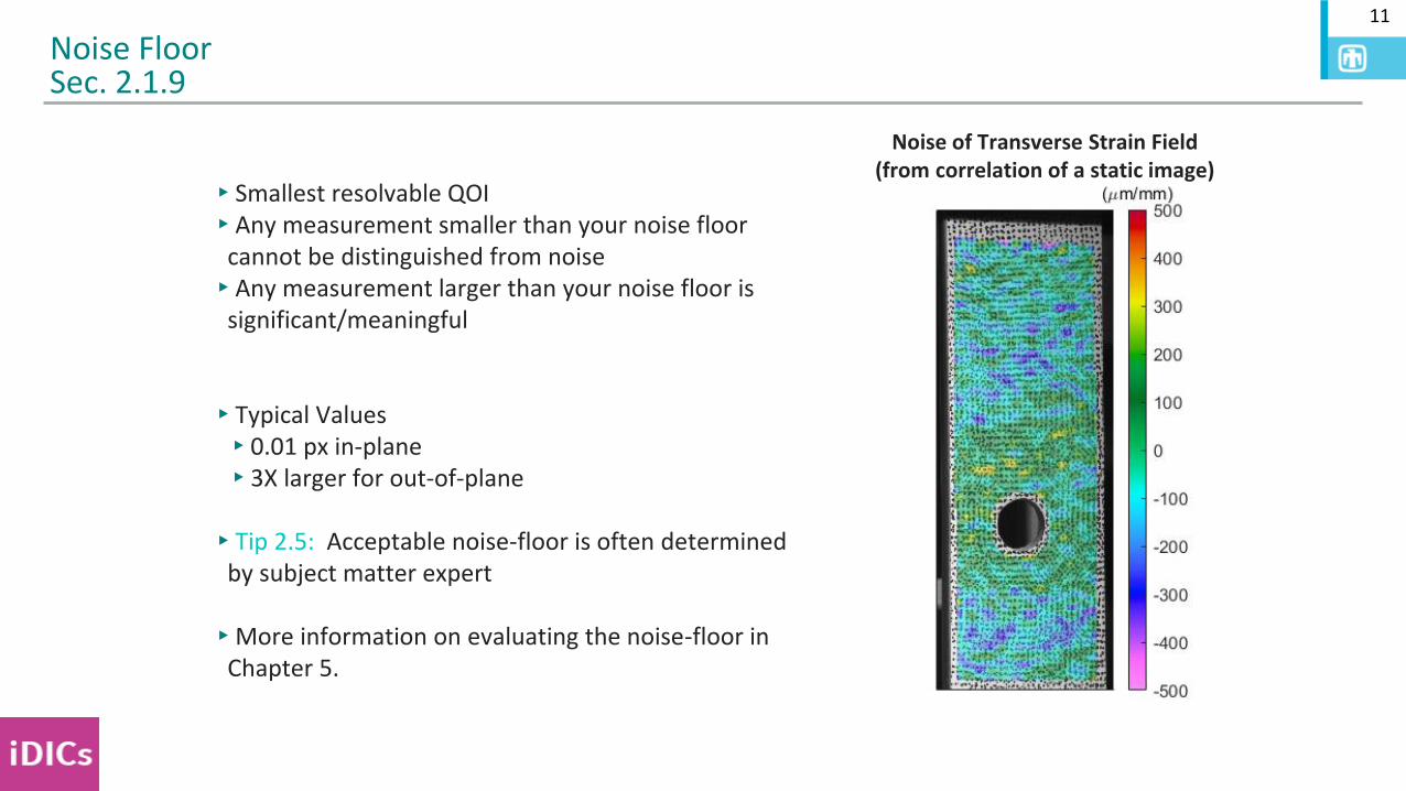
▸Smallest resolvable QOI▸Any measurement smaller than your noise floor
cannot be distinguished from noise▸Any measurement larger than your noise floor is
significant/meaningful
▸Typical Values▸0.01 px in-plane▸3X larger for out-of-plane
▸Tip 2.5: Acceptable noise-floor is often determined by subject matter expert
▸More information on evaluating the noise-floor in Chapter 5.
Noise FloorSec. 2.1.9
Noise of Transverse Strain Field(from correlation of a static image)
12
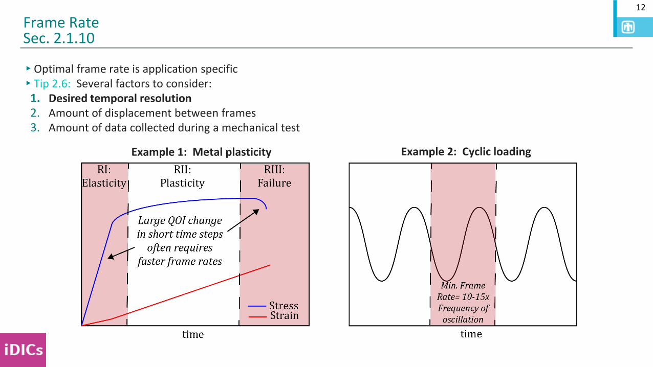
▸Optimal frame rate is application specific▸Tip 2.6: Several factors to consider:
1. Desired temporal resolution2. Amount of displacement between frames3. Amount of data collected during a mechanical test
Frame RateSec. 2.1.10
Example 1: Metal plasticity Example 2: Cyclic loading
13
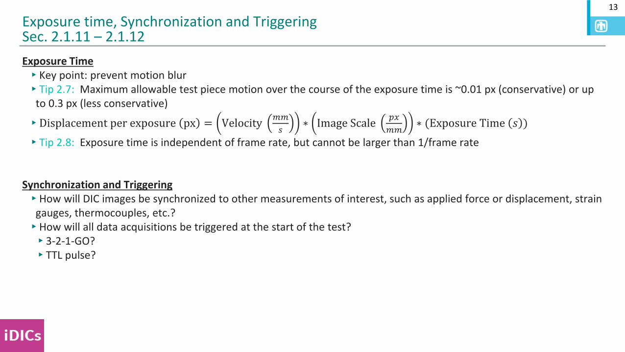
Exposure Time▸Key point: prevent motion blur▸Tip 2.7: Maximum allowable test piece motion over the course of the exposure time is ~0.01 px (conservative) or up
to 0.3 px (less conservative)
▸Displacement per exposure px = Velocity𝑚𝑚
𝑠∗ Image Scale
𝑝𝑥
𝑚𝑚∗ (Exposure Time 𝑠 )
▸Tip 2.8: Exposure time is independent of frame rate, but cannot be larger than 1/frame rate
Synchronization and Triggering▸How will DIC images be synchronized to other measurements of interest, such as applied force or displacement, strain
gauges, thermocouples, etc.?▸How will all data acquisitions be triggered at the start of the test?▸3-2-1-GO?▸TTL pulse?
Exposure time, Synchronization and TriggeringSec. 2.1.11 – 2.1.12
CHAPTER 2:DESIGN OF DIC MEASUREMENTS
SEC. 2.2:EQUIPMENT AND HARDWARE
SAND2020-9051 TR (slides)SAND2020-9046 TR (videos)
15
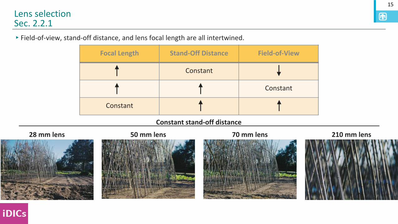
▸Field-of-view, stand-off distance, and lens focal length are all intertwined.
Lens selectionSec. 2.2.1
Focal Length Stand-Off Distance Field-of-View
Constant
50 mm lens28 mm lens 70 mm lens 210 mm lens
Constant stand-off distance
Focal Length Stand-Off Distance Field-of-View
Constant
Constant
Focal Length Stand-Off Distance Field-of-View
Constant
Constant
Constant
16
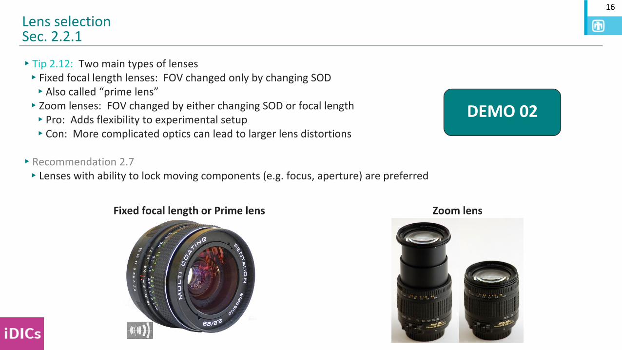
▸Tip 2.12: Two main types of lenses▸Fixed focal length lenses: FOV changed only by changing SOD▸Also called “prime lens”▸Zoom lenses: FOV changed by either changing SOD or focal length ▸Pro: Adds flexibility to experimental setup▸Con: More complicated optics can lead to larger lens distortions
▸Recommendation 2.7▸Lenses with ability to lock moving components (e.g. focus, aperture) are preferred
Lens selectionSec. 2.2.1
Zoom lensFixed focal length or Prime lens
DEMO 02
17
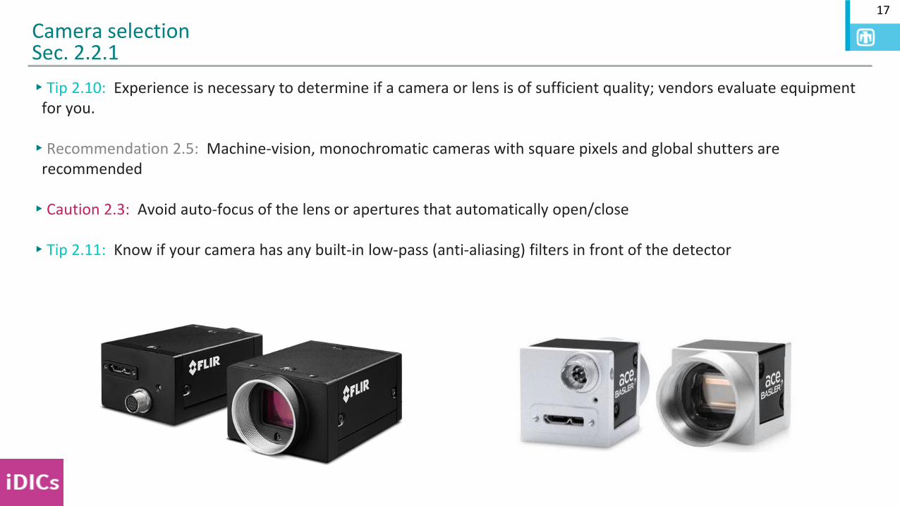
▸Tip 2.10: Experience is necessary to determine if a camera or lens is of sufficient quality; vendors evaluate equipment for you.
▸Recommendation 2.5: Machine-vision, monochromatic cameras with square pixels and global shutters are recommended
▸Caution 2.3: Avoid auto-focus of the lens or apertures that automatically open/close
▸Tip 2.11: Know if your camera has any built-in low-pass (anti-aliasing) filters in front of the detector
Camera selectionSec. 2.2.1
18
▸Caution 2.7: Any relative motion between cameras will induce errors!
▸Include sufficient degrees of freedom for precise adjustment of the cameras/lenses
▸Have a plan for making room for the calibration target
▸Mount camera/lens near its combined center of mass
▸Stabilize and strain relieve cables
▸Ensure camera support structure is stable (can add sandbags)
▸Minimize vibrations being transferred to cameras
General characteristics of mounting system Sec. 2.2.2.1
19
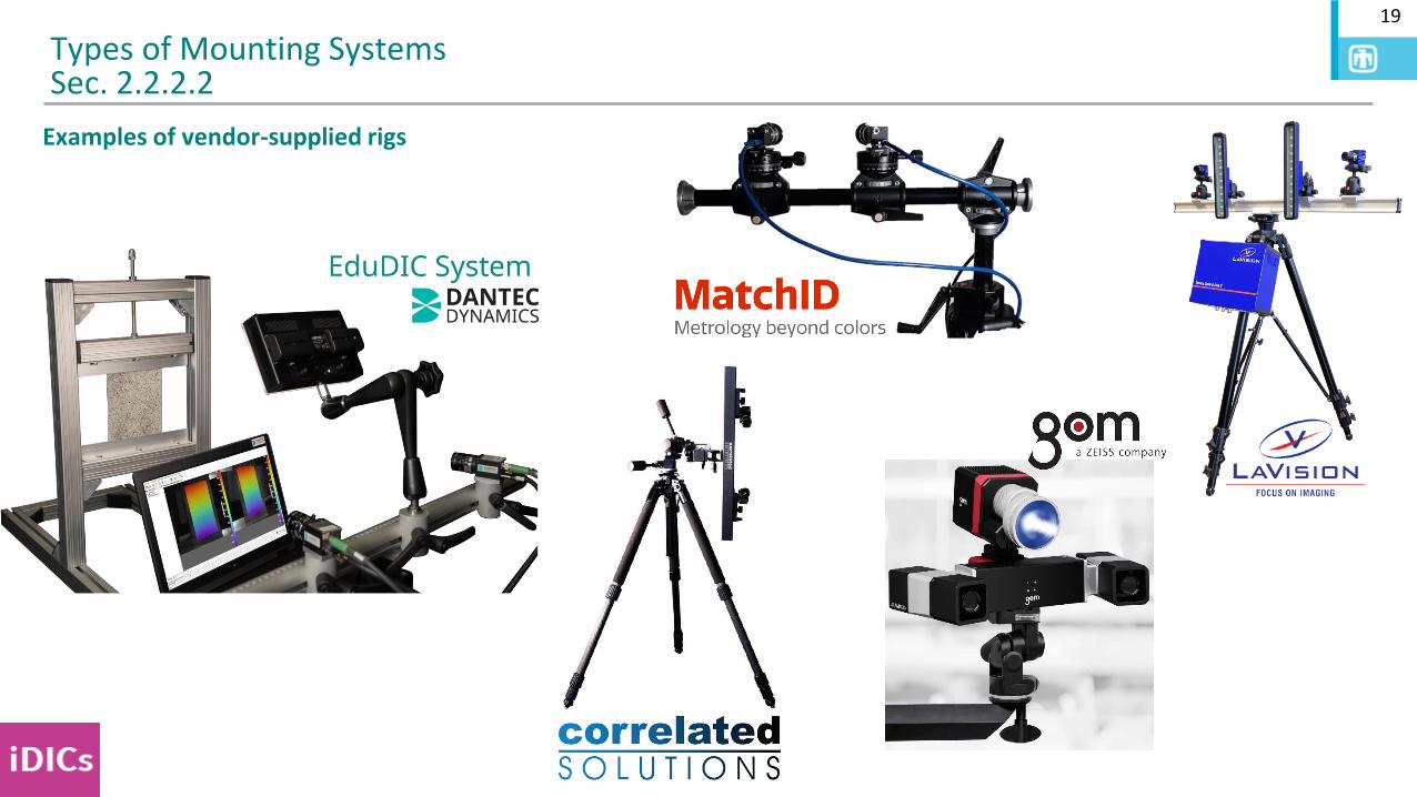
Types of Mounting SystemsSec. 2.2.2.2
Examples of vendor-supplied rigs
20
Build your own mounting system▸This is not an exhaustive list▸iDICs, SEM, SNL, and NIST do not
endorse these companies
Types of Mounting SystemsSec. 2.2.2.2
21
Direction of Deformation
Y
XLong Axis of
Camera Sensor
Stereo plane
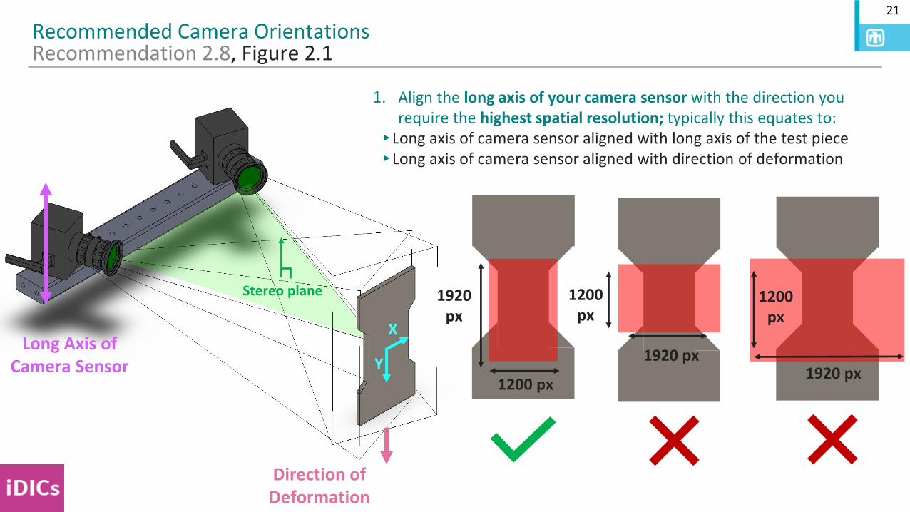
Recommended Camera OrientationsRecommendation 2.8, Figure 2.1
1920 px
1200 px1920 px
1200 px
1. Align the long axis of your camera sensor with the direction you require the highest spatial resolution; typically this equates to:
‣Long axis of camera sensor aligned with long axis of the test piece‣Long axis of camera sensor aligned with direction of deformation
1200 px
1920 px
22
Direction of Deformation
Y
XLong Axis of
Camera Sensor
Stereo plane
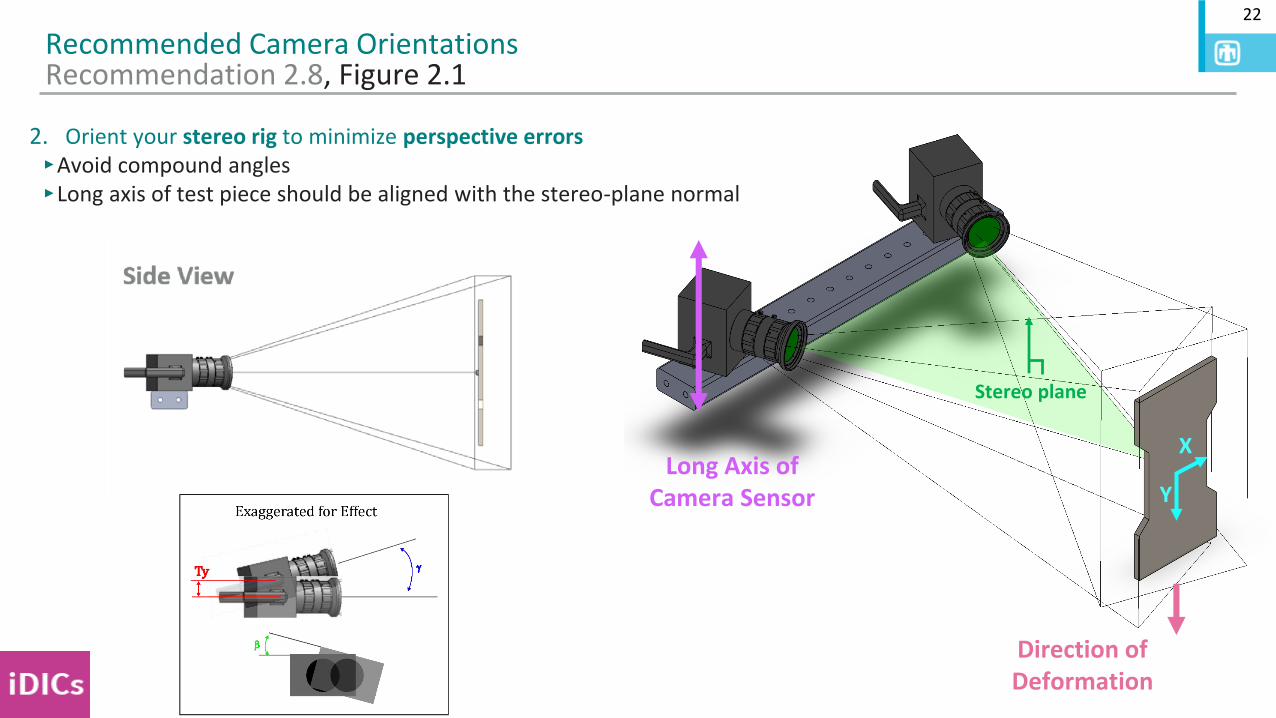
Recommended Camera OrientationsRecommendation 2.8, Figure 2.1
2. Orient your stereo rig to minimize perspective errors‣Avoid compound angles‣Long axis of test piece should be aligned with the stereo-plane normal
23
Direction of Deformation
Y
XLong Axis of
Camera Sensor
Stereo plane
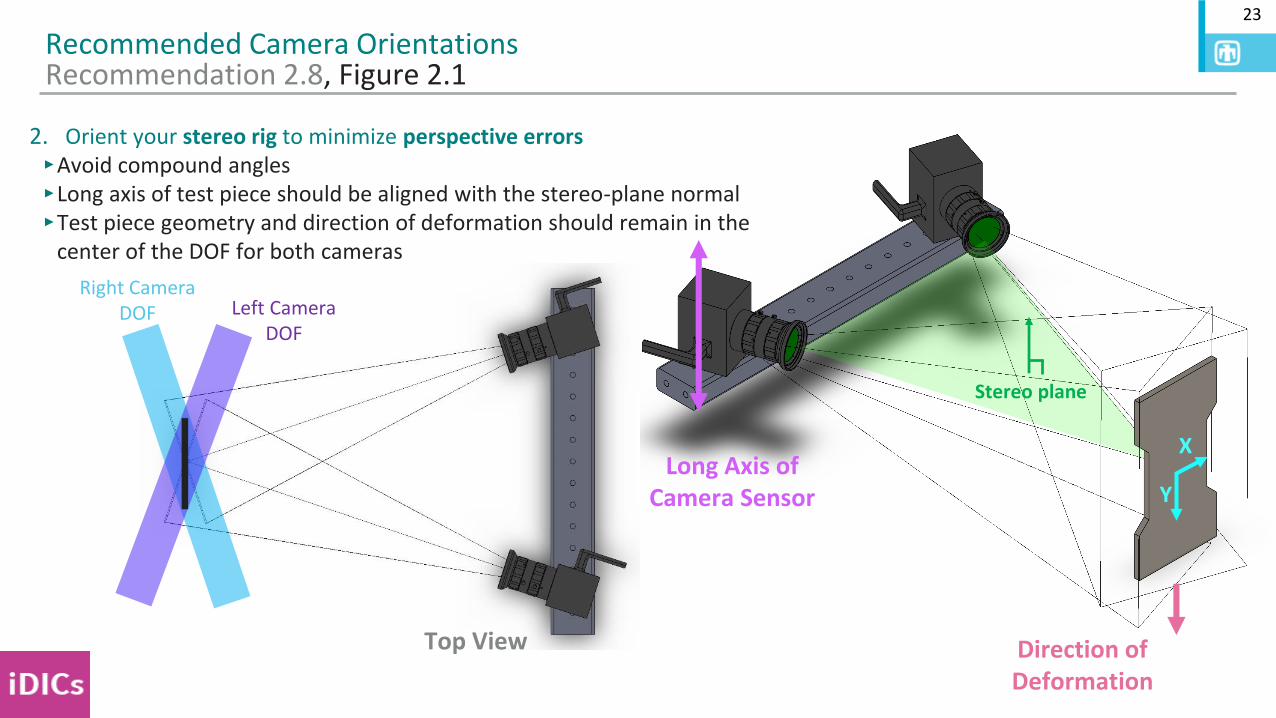
Recommended Camera OrientationsRecommendation 2.8, Figure 2.1
2. Orient your stereo rig to minimize perspective errors‣Avoid compound angles‣Long axis of test piece should be aligned with the stereo-plane normal‣Test piece geometry and direction of deformation should remain in the
center of the DOF for both cameras
Left Camera DOF
Right Camera DOF
Top View
24
Recommended Camera OrientationsRecommendation 2.8, Figure 2.1
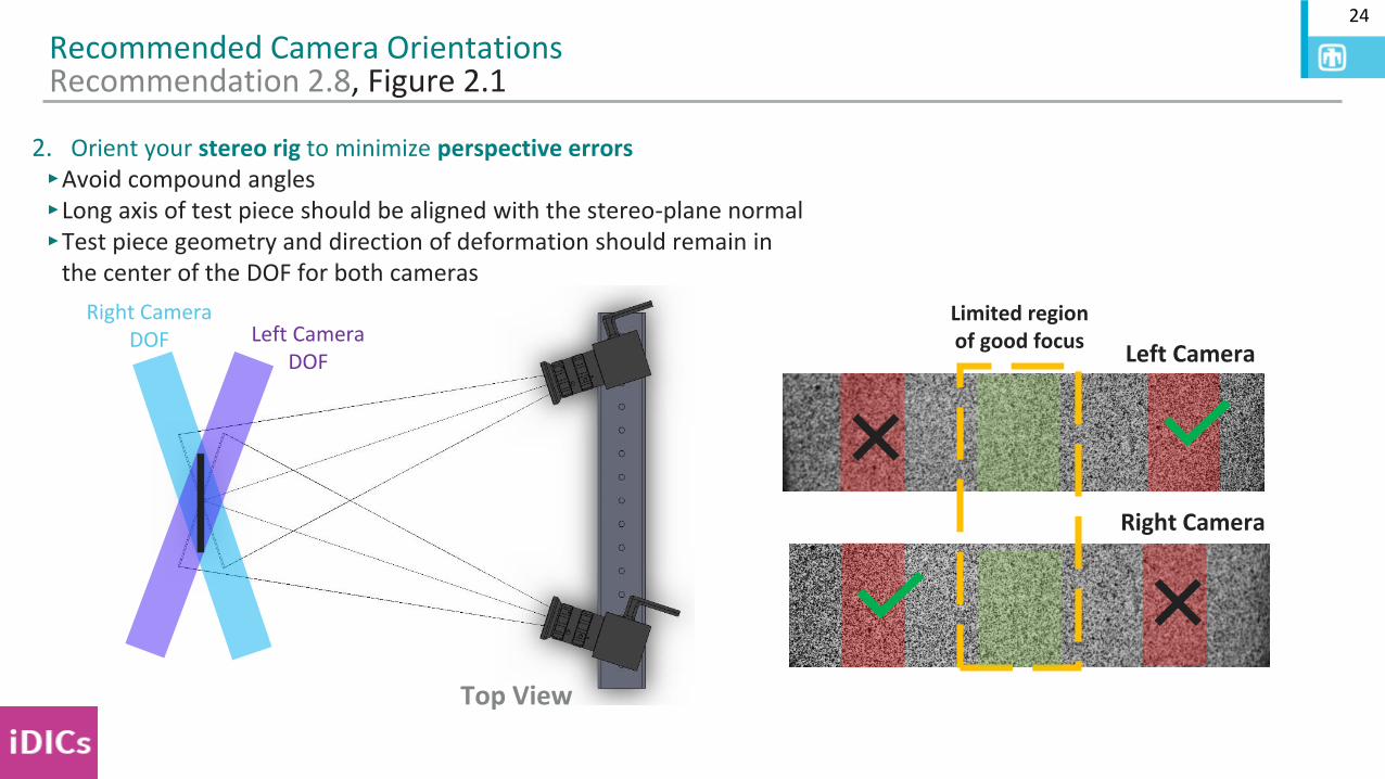
2. Orient your stereo rig to minimize perspective errors‣Avoid compound angles‣Long axis of test piece should be aligned with the stereo-plane normal‣Test piece geometry and direction of deformation should remain in
the center of the DOF for both cameras
Right Camera
Left Camera
Limited region of good focusLeft Camera
DOF
Right Camera DOF
Top View
25
Recommended Camera OrientationsRecommendation 2.8, Figure 2.1
Left Camera DOF
Right Camera DOF
Top View
Left Camera DOF
Right Camera DOF
Top View
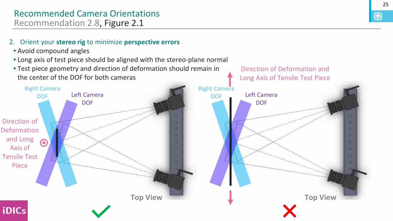
2. Orient your stereo rig to minimize perspective errors‣Avoid compound angles‣Long axis of test piece should be aligned with the stereo-plane normal‣Test piece geometry and direction of deformation should remain in
the center of the DOF for both cameras
Direction of Deformation
and Long Axis of
Tensile Test Piece
Direction of Deformation and Long Axis of Tensile Test Piece
26
Recommended Camera OrientationsRecommendation 2.8
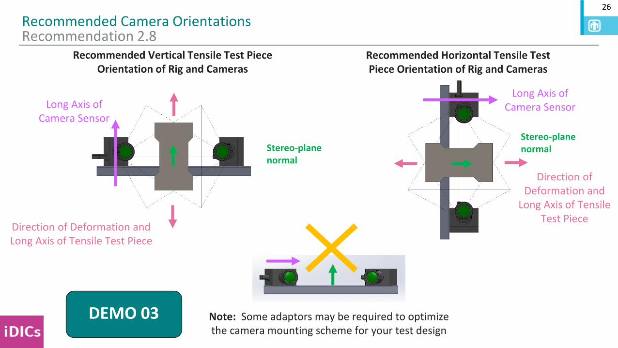
Recommended Vertical Tensile Test Piece Orientation of Rig and Cameras
Direction of Deformation and Long Axis of Tensile Test Piece
Long Axis of Camera Sensor
Note: Some adaptors may be required to optimize the camera mounting scheme for your test design
Recommended Horizontal Tensile Test Piece Orientation of Rig and Cameras
Long Axis of Camera Sensor
Direction of Deformation and
Long Axis of Tensile Test Piece
DEMO 03
Stereo-plane normalStereo-plane
normal
27
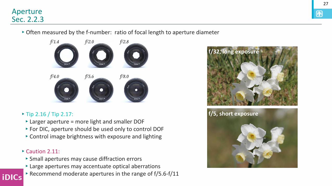
▸Often measured by the f-number: ratio of focal length to aperture diameter
▸Tip 2.16 / Tip 2.17: ▸Larger aperture = more light and smaller DOF▸For DIC, aperture should be used only to control DOF▸Control image brightness with exposure and lighting
▸Caution 2.11: ▸Small apertures may cause diffraction errors▸Large apertures may accentuate optical aberrations▸Recommend moderate apertures in the range of f/5.6-f/11
ApertureSec. 2.2.3
f/32, long exposure
f/5, short exposure
28
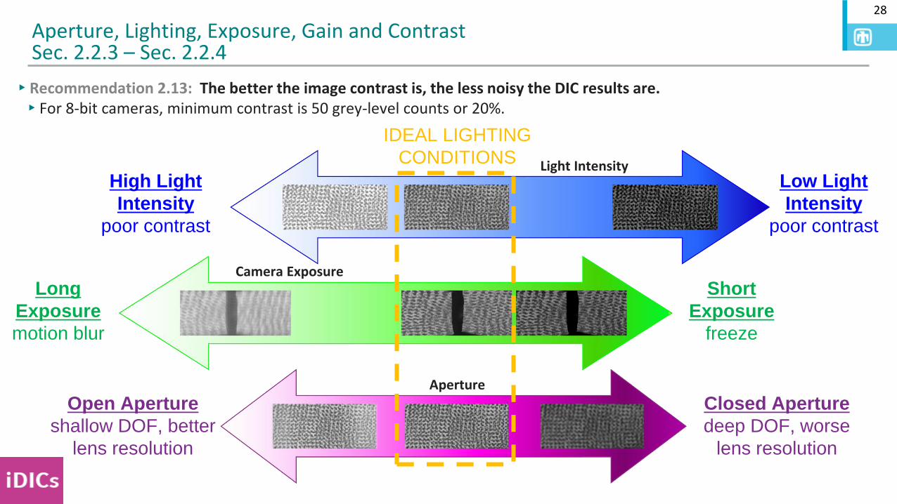
Aperture, Lighting, Exposure, Gain and ContrastSec. 2.2.3 – Sec. 2.2.4
Open Aperture
shallow DOF, better
lens resolution
Closed Aperture
deep DOF, worse
lens resolution
Long
Exposure
motion blur
IDEAL LIGHTING
CONDITIONS
▸Recommendation 2.13: The better the image contrast is, the less noisy the DIC results are.▸For 8-bit cameras, minimum contrast is 50 grey-level counts or 20%.
Light Intensity
Camera Exposure
Aperture
Short
Exposure
freeze
Low Light
Intensity
poor contrast
High Light
Intensity
poor contrast
29
Aperture, Lighting, Exposure, Gain and ContrastSec. 2.2.3 – Sec. 2.2.4
Open Aperture
shallow DOF, better
lens resolution
Closed Aperture
deep DOF, worse
lens resolution
Long
Exposure
motion blur
IDEAL LIGHTING
CONDITIONS
▸Recommendation 2.13: The better the image contrast is, the less noisy the DIC results are.▸For 8-bit cameras, minimum contrast is 50 grey-level counts or 20%.
Light Intensity
Camera Exposure
Aperture
Short
Exposure
freeze
Low Light
Intensity
poor contrast
High Light
Intensity
poor contrast
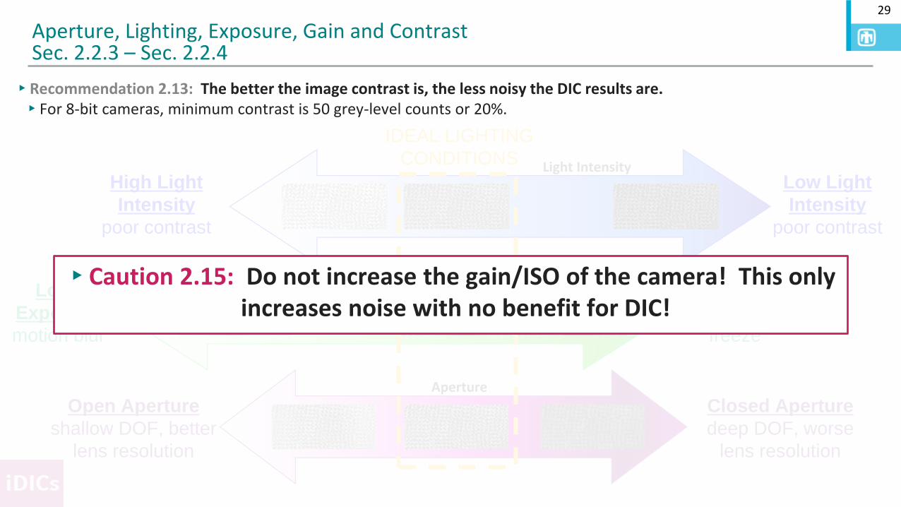
▸Caution 2.15: Do not increase the gain/ISO of the camera! This only increases noise with no benefit for DIC!
30
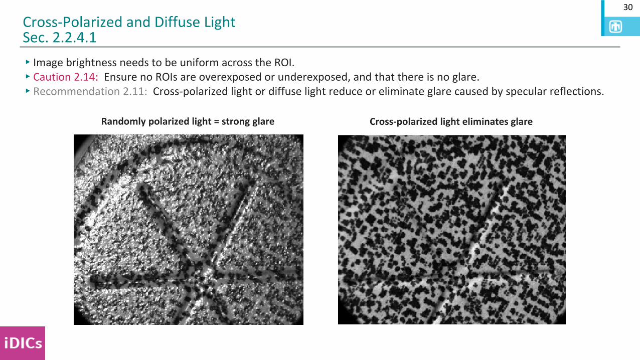
▸Image brightness needs to be uniform across the ROI.▸Caution 2.14: Ensure no ROIs are overexposed or underexposed, and that there is no glare.▸Recommendation 2.11: Cross-polarized light or diffuse light reduce or eliminate glare caused by specular reflections.
Cross-Polarized and Diffuse LightSec. 2.2.4.1
Randomly polarized light = strong glare Cross-polarized light eliminates glare
31
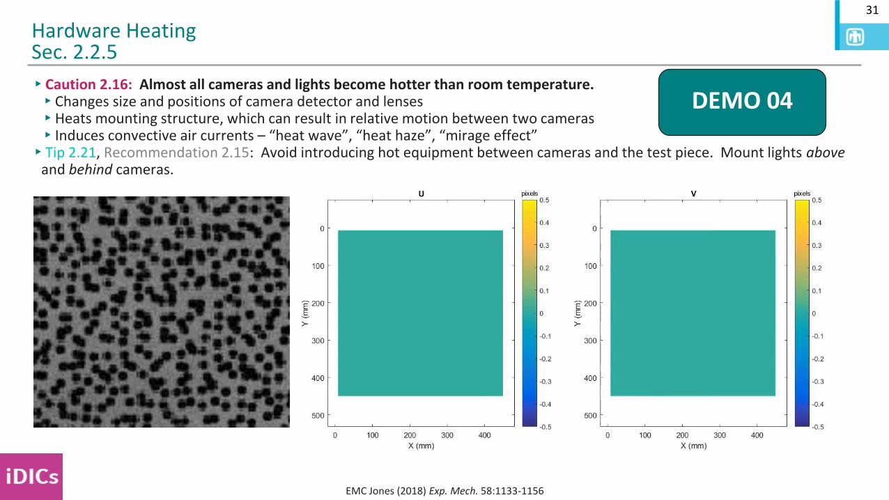
▸Caution 2.16: Almost all cameras and lights become hotter than room temperature.▸Changes size and positions of camera detector and lenses▸Heats mounting structure, which can result in relative motion between two cameras▸Induces convective air currents – “heat wave”, “heat haze”, “mirage effect”
▸Tip 2.21, Recommendation 2.15: Avoid introducing hot equipment between cameras and the test piece. Mount lights aboveand behind cameras.
Hardware HeatingSec. 2.2.5
DEMO 04
EMC Jones (2018) Exp. Mech. 58:1133-1156
CHAPTER 2:DESIGN OF DIC MEASUREMENTS
SEC. 2.3:DIC PATTERN
SAND2020-9051 TR (slides)SAND2020-9046 TR (videos)
33
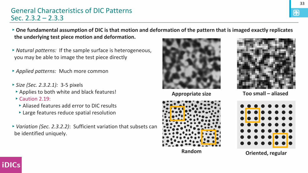
▸One fundamental assumption of DIC is that motion and deformation of the pattern that is imaged exactly replicates the underlying test piece motion and deformation.
General Characteristics of DIC PatternsSec. 2.3.2 – 2.3.3
Appropriate size Too small – aliased
▸Natural patterns: If the sample surface is heterogeneous, you may be able to image the test piece directly
▸Applied patterns: Much more common
▸Size (Sec. 2.3.2.1): 3-5 pixels▸Applies to both white and black features!▸Caution 2.19: ▸Aliased features add error to DIC results▸Large features reduce spatial resolution
▸Variation (Sec. 2.3.2.2): Sufficient variation that subsets can be identified uniquely.
Random Oriented, regular
34
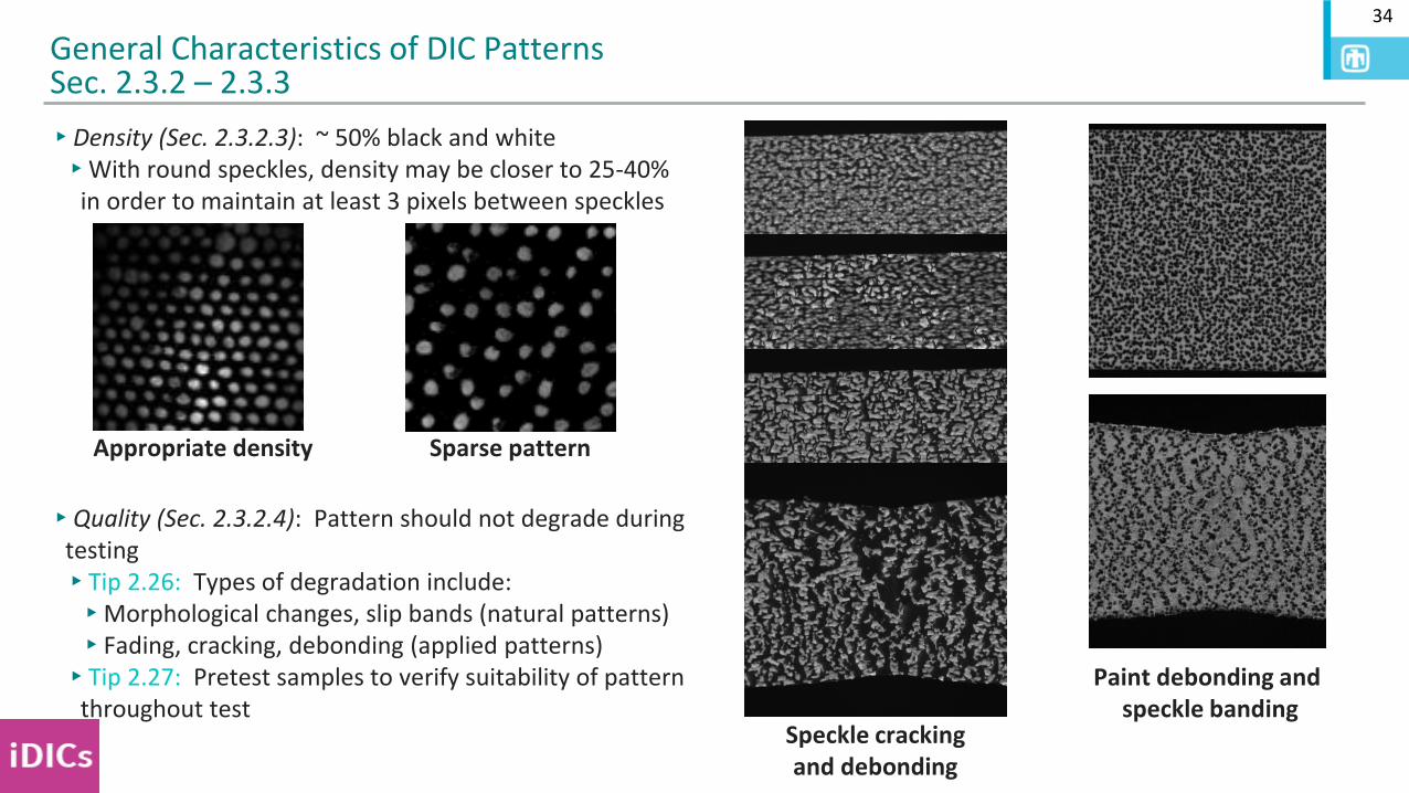
▸Density (Sec. 2.3.2.3): ~ 50% black and white▸With round speckles, density may be closer to 25-40%
in order to maintain at least 3 pixels between speckles
▸Quality (Sec. 2.3.2.4): Pattern should not degrade during testing▸Tip 2.26: Types of degradation include:▸Morphological changes, slip bands (natural patterns)▸Fading, cracking, debonding (applied patterns)▸Tip 2.27: Pretest samples to verify suitability of pattern
throughout test
General Characteristics of DIC PatternsSec. 2.3.2 – 2.3.3
Appropriate density Sparse pattern
Paint debonding andspeckle banding
Speckle crackingand debonding
35
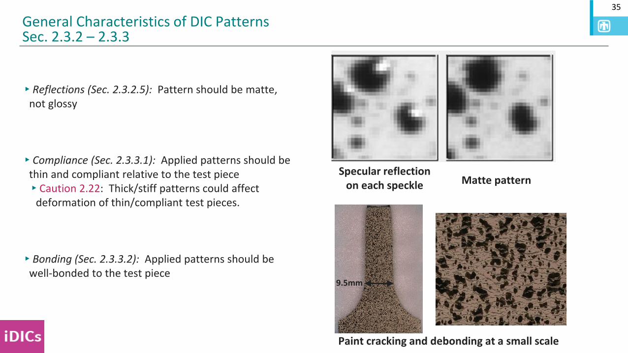
▸Reflections (Sec. 2.3.2.5): Pattern should be matte, not glossy
▸Compliance (Sec. 2.3.3.1): Applied patterns should be thin and compliant relative to the test piece▸Caution 2.22: Thick/stiff patterns could affect
deformation of thin/compliant test pieces.
▸Bonding (Sec. 2.3.3.2): Applied patterns should be well-bonded to the test piece
General Characteristics of DIC PatternsSec. 2.3.2 – 2.3.3
Specular reflection on each speckle Matte pattern
Paint cracking and debonding at a small scale
9.5mm
36
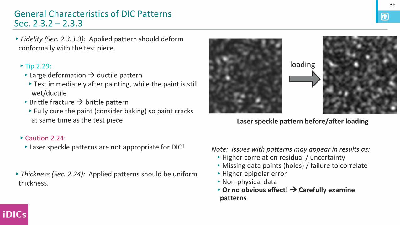
▸Fidelity (Sec. 2.3.3.3): Applied pattern should deform conformally with the test piece.
▸Tip 2.29: ▸Large deformation → ductile pattern▸Test immediately after painting, while the paint is still
wet/ductile▸Brittle fracture → brittle pattern▸Fully cure the paint (consider baking) so paint cracks
at same time as the test piece
▸Caution 2.24:▸Laser speckle patterns are not appropriate for DIC!
▸Thickness (Sec. 2.24): Applied patterns should be uniform thickness.
General Characteristics of DIC PatternsSec. 2.3.2 – 2.3.3
loading
Laser speckle pattern before/after loading
Note: Issues with patterns may appear in results as:▸Higher correlation residual / uncertainty▸Missing data points (holes) / failure to correlate▸Higher epipolar error▸Non-physical data▸Or no obvious effect! → Carefully examine
patterns
37
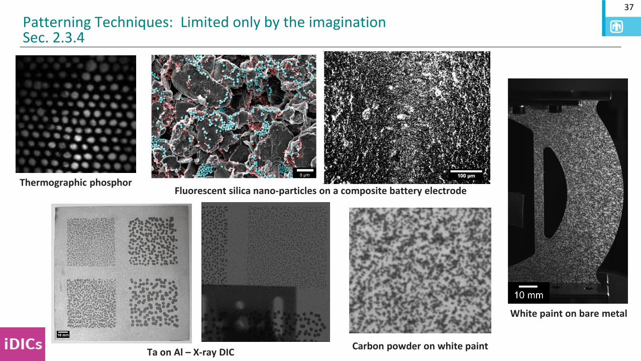
Patterning Techniques: Limited only by the imaginationSec. 2.3.4
Thermographic phosphorFluorescent silica nano-particles on a composite battery electrode
White paint on bare metal
Carbon powder on white paintTa on Al – X-ray DIC