Embed Size (px)
Citation preview

Chapter 2
Contents of the Project

– 7 –
Chapter 2 Contents of the Project
2-1 Basic Concept of the Project
The Project aims to improve the HF broadcasting facilities (Kundu broadcasting) that were
constructed under Japan’s Grant Aid in 1988/1989 with the purpose of providing information
concerning education, sanitation, public health and agriculture, etc. and thereby improving the standard
of living for inhabitants in five targeted provinces.
The anticipated population, that can receive a benefit of Kundu broadcasting in the project
provinces, are as follows.
Planned Broadcasting Station Inhabitant in
the province
Benefit
population
Benefit
population rate
Mt. Hagen (West Highlands Province) 440,025 431,000 98%
Lae (Morobe Province) 539,404 324,000 60%
Kimbe (West New-Britain Province) 184,508 129,000 70%
Vanimo (West-Sepik Province) 185,741 130,000 70%
Goroka (East Highlands Province) 432,972 346,000 80%
Total 1,360,000
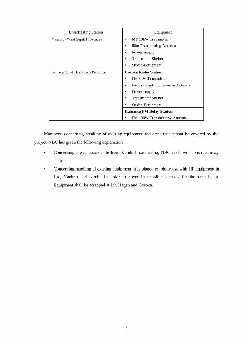
The following equipment shall be supplied by the Project.
Broadcasting Station Equipment
Mt. Hagen (West Highlands Province) • FM 3kW Transmitter
• FM Transmitting Tower & Antenna
• Power-supply
• Studio-Equipment
Lae (Morobe Province) • MF 10kW Transmitter
• 80m Transmitting Antenna
• Power-supply
• Transmitter Shelter
• Recording/Player
Kimbe (West New Britain Province) • MF 10kW Transmitter
• 80m Transmitting Antenna
• Power-supply
• Transmitter Shelter
• Recording/Player
– 8 –
Broadcasting Station Equipment
Vanimo (West Sepik Province) • MF 10kW Transmitter
• 80m Transmitting Antenna
• Power-supply
• Transmitter Shelter
• Studio-Equipment
Goroka Radio Station
• FM 3kW Transmitter
• FM Transmitting Tower & Antenna
• Power-supply
• Transmitter Shelter
• Studio-Equipment
Goroka (East Highlands Province)
Kainantu FM Relay Station
• FM 100W Transmitter& Antenna
Moreover, concerning handling of existing equipment and areas that cannot be covered by the
project, NBC has given the following explanation:
• Concerning areas inaccessible from Kundu broadcasting, NBC itself will construct relay
stations.
• Concerning handling of existing equipment, it is planed to jointly use with HF equipment in
Lae, Vanimo and Kimbe in order to cover inaccessible districts for the time being.
Equipment shall be scrapped at Mt. Hagen and Goroka.

– 9 –
2-2 Basic Design of the Requested Japanese Assistance
2-2-1 Design Policy
(1) Site Selection
As the government based broadcasting corporation of PNG, NBC conducts Karai broadcasting
(nationwide general broadcasting in English) and Kundu broadcasting (provincial broadcasting in
local languages). The Kundu broadcasting is carried out by local stations located in each of the
country's 19 provinces. (two were constructed under PNG own fund and 17 were provided under
Japan’s Grant Aid in 1988/1989).
As a result of basic design study at the eight requested sites, three stations were excepted because
acquisition of construction sites and securing of operation and maintenance funding from
provincial governments, were difficult , and five stations were eventually selected. (See Table 2-1
Study Summary Sheet for an outline of the survey of the eight sites).
Project Target Sites (5 stations) Unsuitable Sites (3 stations)
Mt. Hagen (West Highlands Province)
Lae (Morobe Province)
Kimbe (West New Britain Province)
Vanimo (West Sepik Province)
Goroka (East Highland Province)
Kundiawa (Chimbu Province)
Wabag (Enga Province)
Wewak (East Highlands Province)
(2) Selection of the Broadcasting Mode
Concerning the selection of broadcasting mode, rather than adhering solely to MF broadcasting
as request, it was decided to apply the following criteria taking into account geographical
condition for Kundu broadcasting.
HF broadcasting: This mode shall not be adopted in the Project for the following reasons.
Current HF broadcasting will be suspended in 2015 according to ITU
recommendations. HF broadcasting adopted in the Project will thus have
a remaining service life of 10 years. Moreover, since HF broadcasting has
poor sound quality and is in competition with private broadcasting stations
in Papua New Guinea, it was deemed more appropriate to select MF and
FM at the expense of some geographical coverage in order to attract
listeners.

– 10 –
MF broadcasting: In coastal areas, since transmitting station sites can be secured, MF
broadcasting is the best option (Lae, Kimbe, Vanimo)
The sound quality of MF broadcasting has improved in recent times due to
utilization of pre-emphasis effect with general receiver-transmitter
characteristics. In this sense, MF broadcasting is now able to compete
with FM broadcasting in terms of sound quality. Decision of whether to
select MF broadcasting or FM broadcasting is mainly dictated by
topographical conditions.
As coastal parts of Papua New Guinea stretch over relatively expansive
plains and have high ground conductivity, MF broadcasting is more
advantageous.
FM broadcasting: In highland areas, FM broadcasting is the optimum option because it
enables wide service areas to be secured (Mt. Hagen, Goroka).
This media offers good sound quality and high performance against noise.
However, in order to secure service areas wider than MF broadcasting,
antenna shall be put on high position.
In other words, when the height difference between the service area and
antenna installation height is 100 m, the radio wave coverage is limited to
15 km due to curvature of the globe. However, when higher transmitting
station positions can be secured in mountain areas, a broadcasting service
area can be secured large area.
Mt. Hagen, for example, many people live in valley areas approximately
300 feet (90 m) below the transmitting point. If a 60 m steel tower is
constructed here, the height difference becomes 150 m and service
coverage of approximately 40 km can be expected.
(3) Determination of Transmission Frequency and Output Power
Determination was carried out according to the following items.
1) MF Broadcasting
According to frequencies and transmission output power registered in the ITU

– 11 –
2) FM Broadcasting
Frequency allocation: Width of 200 kHz shall be adopted within the allocable bandwidth
(87.5-108 MHz). Moreover, width of 800 kHz shall be adopted at same transmitting
stations.
Transmitter output power: This shall be determined according to the scope and geographical
features, etc. of target broadcasting areas.
3) Frequency Assignment
All assigned frequencies in 6 sites are authorized in writing by PANGTEL in PNG.
(4) Service Areas
The required field strengths in the service area of broadcasting are as follows:
1) MF broadcasting
Daytime: 60 dBu V/m (1 mV/m) (In consideration of external noise and receiver
performance)
2) FM broadcasting
Monophonic broadcasting: 48 dBu V/m (0.25 mV/m)
Stereophonic broadcasting: 54 dBu V/m (0.5 mV/m) (According to CCIR Rec. 412-3)
(5) Transmitter Equipment Shelters
In the Radio Station Improvement Project that was implemented in 1988/89, the PNG side
constructed transmitting station buildings using its own funds, while the Japan side supplied only
transmitter equipment by Grant Aid. That equipment has now entered the wear and tear stage of
its life cycle, and deterioration of facilities is caused by damp and insect from out side. In
implementing the project, no setting up of administration building for transmitting stations. All
equipment shall be installed in container type shelter to prevent a problem of damp, salt damage
and insect damage come from outside.
(6) Lifespan of Equipment
Average values of equipment lifespan in Japan are as given in the following table.

– 12 –
Equipment Average Life
Sound console 12-14 years
FPU 10-12 years
Emergency generator 18 years
Power receiving facility 21 years
Storage battery 8-9 years
Air conditioning 15 years
Blower 15 years
Radio transmitter 18 years
The above table is based on provision of an appropriate equipment environment and proper
preventive maintenance, and thus cannot be directly applied to PNG.
The lifespan of equipment planned in the Project is as follows.
Equipment Design Life
Span Basis
Sound console 5-7 years Use a professional model with guaranteed parts supply of five years.
FPU 7 years Preventive maintenance is difficult, like in Japan
Emergency generator 12 years Same as above
Power receiving facility 14 years Same as above
Air conditioning 7years Taking climate into account (twice as much usage as in Japan)
Blower 10 years Preventive maintenance is difficult, like in Japan
Radio transmitter 12 years Same as above
(7) Spare Parts Supply Guarantee
Supply of genuine spare parts is guaranteed for 5 years in the case of professional equipment and
10 years in the case of broadcasting equipment. These guarantee periods rise to 7 years and 15
years respectively when it comes to equivalent parts to the above.

− 13 −
Fig. 2-1 Project Outline Drawing
Studio Transmitting Station Station Program
Production FM/STL
Transmitter
Distance between Studio and TX Stn.
FM/STL Receiver
MF/FM Transmitter TX Antenna, Tower
Mt. Hagen
FM
91.5MHz
3kW
Lae
MF
810kHz
10kW
Kimbe
MF
900kHz
10kW
Vanimo
MF
585kHz
10kW
Goroka
FM
91.9KHz
3kW
Studio Equipment
3kW FM TX
E/G 45kVA
Tower 60m
Planned with NBC’s own funding
CD Recorder
1kW FM TX
FM
from Studio E/G
45kVA
10kW MF TX
TX Antenna 80m RX
10km
CD Recorder
TX
STL
E/G
45kVA 10kW MF TX
TX Antenna 80m
RX 0.5km STL
from Studio
Studio Equipment
TX
TX Antenna 80m
2km STL STL
E/G
45kVA 10kW MF TX
RX
from Studio
STL
E/G
45kVA
Studio Equipment
TX 1km STL Tower 60m
Kainantu FM Relay Stn
RX 3kW FM TX
100W
91.1MHz
from Goroka via TELIKOM line

− 14 −
Table 2-1 Study Summary Sheet
Feasibility of MF/FM Transmitting Station Construction Broadcasting Current Conditions and Operation and Maintenance Capacity
Appropriate Broadcasting Mode
Site (Province)
MF FM
Expected Population Coverage
(1,000 people)
Transmitter Installation
Transmitting Tower
Transmitter Output
Broadcasting Conditions and Budget Situation
Future Support Policy of Provincial Government
(Possibility of Commercial Broadcasting)
Operation and
Maintenance Features and Notes
① Kundiawa [ Simbu ]
× Survey of 2
sites Land is small
× No land ― ― ―
• The current operating cost subsidy is small.
• Broadcasting has been suspended for 1.5 months because of non-payment of the electricity tariff.
• The governor is very enthusiastic about enhancing broadcasting.
• Increased operating budget is promised, but doubts remain over operation and maintenance.
Difficult
② Mt. Hagen [ West Highlands ]
× Land is small
Next to station
building
FM: 98% (431)
Inside station building
Self-supporting 60 m, 3 kW
• Operating costs are almost totally secured.
• Broadcasting is suspended from early morning till 08.00 in order to save on electricity expenses.
• Sanitary, economic and social programs are currently broadcast in Kundu Service.
• Commercial broadcasting is scheduled in central commercial areas within the highlands.
Possible
• This area already has two existing FM station, so FM is appropriate.
• Population coverage here is the highest in the country.
• Coffee production area and tourism area
③ Lae [ Morobe ]
× Expected
coverage is low
MF: 60% (323) Shelter Guyed-mast
80 m, 10 kW
• Financial support by the provincial government is clearly indicated.
• There is enough operating budget.
• Equipment renewal using own funds is possible in future.
• The provincial government has promised continued support.
• Closer cooperation with NBC is stressed.
• Commercials are already underway on a trial basis.
Possible
• Population coverage is second highest.
• A commercial city and important base for port transportation
④ Kimbe [ West New Britain ]
× Expected
coverage is low
MF: 70% (129) Shelter Guyed-mast
80 m, 10 kW
• Financial support changes every year.
• In 2001, studio equipment was renewed using provincial funds
• Broadcasting is suspended from early morning till 08.00 in order to save on elect ricity expenses.
• There is a large response from listeners.
• The provincial government has promised support of operating expenses.
• The province understands the importance of broadcasting in education, sanitation, economic development and disaster countermeasure policies.
• Commercials are already underway on a trial basis.
Possible
• Relations are close between the provincial government and NBC.
• This year, damage was incurred by volcanic eruption.
− 15 −
Feasibility of MF/FM Transmitting Station Construction Broadcasting Current Conditions and Operation and Maintenance Capacity
Appropriate Broadcasting Mode
Site (Province)
MF FM
Expected Population Coverage
(1,000 people)
Transmitter Installation
Transmitting Tower
Transmitter Output
Broadcasting Conditions and Budget Situation
Future Support Policy of Provincial Government
(Possibility of Commercial Broadcasting)
Operation and
Maintenance Features and Notes
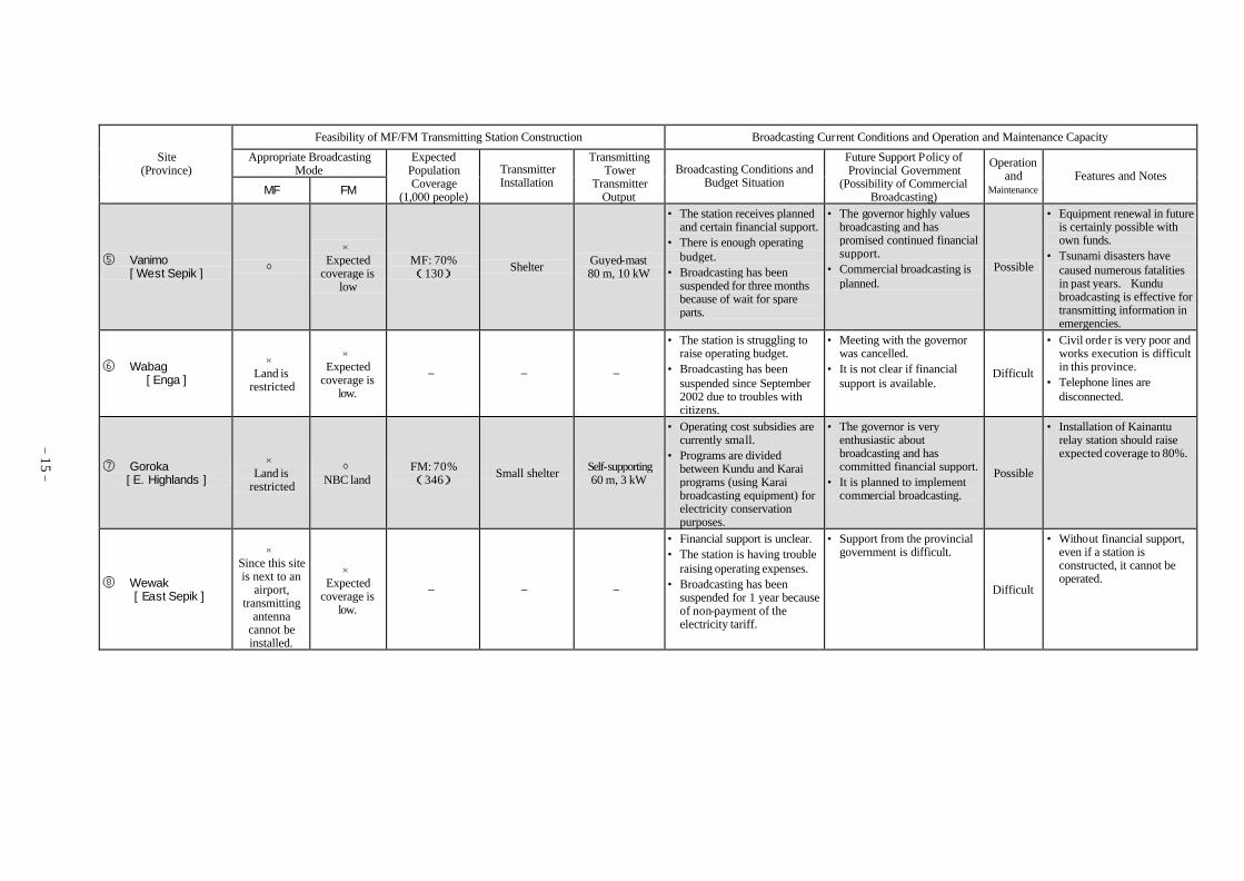
⑤ Vanimo [ West Sepik ]
× Expected
coverage is low
MF: 70% (130) Shelter Guyed-mast
80 m, 10 kW
• The station receives planned and certain financial support.
• There is enough operating budget.
• Broadcasting has been suspended for three months because of wait for spare parts.
• The governor highly values broadcasting and has promised continued financial support.
• Commercial broadcasting is planned.
Possible
• Equipment renewal in future is certainly possible with own funds.
• Tsunami disasters have caused numerous fatalities in past years. Kundu broadcasting is effective for transmitting information in emergencies.
⑥ Wabag [ Enga ]
× Land is
restricted
× Expected
coverage is low.
― ― ―
• The station is struggling to raise operating budget.
• Broadcasting has been suspended since September 2002 due to troubles with citizens.
• Meeting with the governor was cancelled.
• It is not clear if financial support is available.
Difficult
• Civil order is very poor and works execution is difficult in this province.
• Telephone lines are disconnected.
⑦ Goroka [ E. Highlands ]
× Land is
restricted
NBC land
FM: 70% (346) Small shelter Self-supporting
60 m, 3 kW
• Operating cost subsidies are currently small.
• Programs are divided between Kundu and Karai programs (using Karai broadcasting equipment) for electricity conservation purposes.
• The governor is very enthusiastic about broadcasting and has committed financial support.
• It is planned to implement commercial broadcasting.
Possible
• Installation of Kainantu relay station should raise expected coverage to 80%.
⑧ Wewak [ East Sepik ]
×
Since this site is next to an
airport, transmitting
antenna cannot be installed.
× Expected
coverage is low.
― ― ―
• Financial support is unclear. • The station is having trouble
raising operating expenses. • Broadcasting has been
suspended for 1 year because of non-payment of the electricity tariff.
• Support from the provincial government is difficult.
Difficult
• Without financial support, even if a station is constructed, it cannot be operated.

– 16 –
(8) Construction Methods Taking Natural and Social Conditions into Account
1) The six sites in the project cover a wide area including coastline, islands and highland areas,
and detailed consideration will need to be given to works schedules because natural
conditions and even the timing of rainy and dry seasons differ in each region.
2) In particular, construction of MF transmitting antennas as well as radial earth, and FM
transmitting antennas and transmitting towers shall be carried out in low rainfall season in
each area.
3) MF transmitting antennas in coastal and island areas located close to the seashore will need
to have countermeasures against salt damage.
4) In those Project sites that are hot and damp throughout the year, equipment installation sites
shall be adequately prepared so as to enable long-term and stable operation of the
transmitting equipment.
5) Concerning transmitter shelter installation methods and installation places, measures shall
be taken into account against localized torrential rain during the rainy season.
(9) Procurement Plan
• Project equipment is divided between three MF stations and three FM stations.
Concerning FM Transmitter, since domestic production in Japan has been greatly reduced, if
procurement is limited to domestic products only, they will need to be specially ordered and
will be very expensive. Therefore, it is appropriate to also include third-country products
(OECD countries).
• Concerning other transmitter, domestic products shall be adopted.
(10) Local Contractor Utilization Plan
Installation methods that local contractors are familiar with shall be adopted. Moreover, it is
desirable that existence of local agents be made a selecting condition for maintenance of
emergency generator and air conditioners in order to make maintenance more smooth after
completion of the project.
Utilization of local contractors shall be considered in the following works.
• Floor foundation works for transmitter shelters and emergency generator
• Antenna and steel tower foundation works
• Inland transportation

– 17 –
• General labor
(11) Works Period
Works shall be completed within 11 months after the contract.
(12) Socioeconomic Conditions
The receiver ownership situation according to UNESCO statistics is as follows.
Radio Receiver TV
Year Total Owned
Number
Number
/1000 people
Total Owned
Number
Number
/1000 people
1970 80,000 33
1975 110,000 40
1980 180,000 58
1985 230,000 67
1990 280,000 73 9,000 2.3
1991 288,000 73 9,000 2.3
1992 298,000 74 10,000 2.5
1993 310,000 75 12,000 2.8
1994 320,000 76 12,000 2.9
1995 330,000 77 15,000 3.5
1996 400,000 91 40,000 9.1
1997 410,000 91 42,000 9.3
The sales prices of TV sets and radios in supermarkets are as follows:
Portable radio (HF, MF, FM) : 35 kina
Radio cassette (HF, MF, FM) : 240 kina
20 inches TV set : 1052 kina
The following table gives a case of annual salaries at a provincial NBC broadcasting station.
Staff No. Job Description Annual Salary (kina)
No.1 Station manager 24,076.00
No.2 Vice station manager 21,840.00
No.3 Senior staff (grade 7) 14,939.00
No.4 Senior staff (grade 7) 14,939.00

– 18 –
Staff No. Job Description Annual Salary (kina)
No.5 Senior staff (grade 7) 16,474.00
No.6 Senior staff (grade 6) 12,090.00
No.7 Senior staff (grade 5) 9,821.00
No.8 Senior staff (grade 5) 9,821.00
No.9 Senior staff (grade 6) 10,088.00
No.10 Senior staff (grade 4) 8,990.00
No.11 Driver (grade 2) 7,960.00
Judging from the above receiver prices and salary levels, the UNESCO figures for receiver
ownership are too low, because according to interviews carried out in PNG, it seems ownership
also including car radios is far more widespread.
If improvement of radio program content it is made as project object as necessary information for
improving the standard of living of inhabitants, education, health and agriculture etc., it should be
possible to increase the number of audiences.
(13) Policy for the Operation and Maintenance by the Implementing Agency
Following the revision of the low in 1996, the Kundu broadcasting utility has been operated
under irregular funding with the central government furnishing personnel expenses and provincial
governments covering operation and maintenance costs.
In the Project, in order to ensure definite financial support from provincial governments and to
stabilize operation and maintenance of Kundu broadcasting, the Study Team met with provincial
governors and officials to confirm the necessity of Kundu broadcasts in each province and secure
commitment for financial support.
– 19 –
2-2-2 Basic Plan
2-2-2-1 Equipment Plan
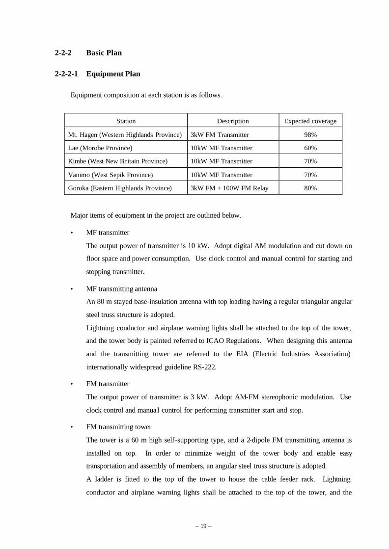
Equipment composition at each station is as follows.
Station Description Expected coverage
Mt. Hagen (Western Highlands Province) 3kW FM Transmitter 98%
Lae (Morobe Province) 10kW MF Transmitter 60%
Kimbe (West New Br itain Province) 10kW MF Transmitter 70%
Vanimo (West Sepik Province) 10kW MF Transmitter 70%
Goroka (Eastern Highlands Province) 3kW FM + 100W FM Relay 80%
Major items of equipment in the project are outlined below.
• MF transmitter
The output power of transmitter is 10 kW. Adopt digital AM modulation and cut down on
floor space and power consumption. Use clock control and manual control for starting and
stopping transmitter.
• MF transmitting antenna
An 80 m stayed base-insulation antenna with top loading having a regular triangular angular
steel truss structure is adopted.
Lightning conductor and airplane warning lights shall be attached to the top of the tower,
and the tower body is painted referred to ICAO Regulations. When designing this antenna
and the transmitting tower are referred to the EIA (Electric Industries Association)
internationally widespread guideline RS-222.
• FM transmitter
The output power of transmitter is 3 kW. Adopt AM-FM stereophonic modulation. Use
clock control and manua l control for performing transmitter start and stop.
• FM transmitting tower
The tower is a 60 m high self-supporting type, and a 2-dipole FM transmitting antenna is
installed on top. In order to minimize weight of the tower body and enable easy
transportation and assembly of members, an angular steel truss structure is adopted.
A ladder is fitted to the top of the tower to house the cable feeder rack. Lightning
conductor and airplane warning lights shall be attached to the top of the tower, and the

– 20 –
tower body is painted referred to ICAO Regulations.
• FM Relay station
Out put power of FM repeater transmitter is 100W, and program signal is transmitted from
Goroka station using TELICOM line. Clock control and manual operation shall be used to
start and stop of the repeater.
• Transmitter shelter
In consideration of room temperature rise caused by heat dissipation of Equipment and
radiation of sunlight, adopt sealed circuit air-cooling with room temperature set at 26 °C.
Air conditioners, ventilation equipment, fluorescent lights and sockets shall be set up,
however, shelters shall only accommodate transmitters and peripheral equipment and shall
not combine office functions.
• Engine generator
No automatic functions are adopted for starting and stopping. During power outages,
station staff will start generator manually, and the reverse procedure is followed to stop
generator when power is restored.
In particular, concerning emergency generator installed in highland areas, it is given to
reduced capacity resulting from high altitude.
Moreover, main fuel tanks shall have enough capacity to hold a 7-day supply taking into
account broadcasting time, frequency of power outages and methods of refueling.
• Studio Equipment
Studio equipment consists of DAT, CD Rec/Rep and CD Rep based around 12 ch audio
mixer. The purpose is to improve the sound quality of studio production and enable
continuous transmission of spot programs.
Equipment Notes
Audio mixer Input 12ch (Stereophone 8ch Monophonic 4ch)
Digital audiotape
recorder/player
Utilizing free write and erase functions to record general studio
programs and other materials for program production.
CD Rec/Rep
CD Player
Utilize the paging function to freely access to required programs.
The objective is to edit general program recorded on DAT into one
day's programs.
Other Headphones, ADA, Jack panels, Racks

– 21 –
Moreover, concerning stations where network studio equipment has already been installed
by NBC (Lae, Kimbe), it has been decided to install only CD recorders/players.
2-2-2-2 Basic Plan of Equipment for Each Station
(1) Mt. Hagen (West Highlands Province) Improvement Plan
Attach an FM transmitting station to the existing studio and build a 60m steel tower with a 2
dipole 2:2 antenna (1:1:1:1), in order to secure expected coverage of 98%.
The equipment composition is as follows:
Audio equipment for studio 1 set
3 kW FM transmitter 1 set
Transmitting tower 60 m 1 set
Transmitting antenna 2 dipole (1:1:1:1) 1 set
Engine generator 45 kVA 1 set

– 22 –
Table 2-2 Mt. Hagen FM Station Equipment
Name of Equipment Quantity Description
A Network Studio Equipment 1 Audio Mixer with Console 1 set with console
Input 12 (Mono 4, stereo 8), Prog. Output 2(mono 1, stereo 1)
2 Dig ital Audio Tape Rec/Rep 1 set DAT format 3 Compact Cassette Tape Rec/Rep 1 set 4 CD Rec/Rep 2 sets Rec: CD-R/CD-RW, Rep:CD/CD-R/CD-RW 5 CD Player 1 set 6 Telephone Pick-up 1 set With Telephone Set 7 Audio Monitor Speaker 1 set For mixing 2, for MCR output 2 8 Headphone 2 sets For both ears 9 Audio Distribution Amplifier 1 lot More than 4 output for 1 input, necessary
numbers for system construction
10 Audio Jack Panel 1 lot Necessary numbers for system construction
11 Patch Code 1 set 30cm cable bounded 5 cables × 4, 60cm cable bounded 5 cables × 4
12 Equipment Rack 1 set
13 Equipment Wagon 1 set
14 Microphone 1 set Dynamic type 2, Condenser type 1
15 Microphone Stand 1 set DJ type 1, Desk type 1, Boom type 1
16 Cough Box 2 sets
17 Earphone 2 sets For single ear
18 Microphone Cable 1 set 5m × 3
19 Microphone Connector Panel 1 set With Box
20 On-air Lamp 2 sets
21 Guest Table 1 set
22 Chair for Operation 3 sets For Studio staff
23 Clock 1 set Wall type, Quartz

– 23 –
Name of Equipment Quantity Description
B Transmitting Station 1 Program Input and Monitoring Equipment 1 set Line transformer, limiting amplifier, level meter,
audio monitor 2 FM Transmitter 1 set 3kW, 91.5MHz 3 Output Change-over Switch 1 set For antenna/dummy load 4 Dummy Load 1 set 3kW 5 Feeder Cable 1 set With Dehydrator 6 Transmitting Antenna 1 set 2 dipole antenna (1:1:1:1), Power divider, FM
Transmitting tower with obstruction light & obstruction marking by ICAO (60m height)
7 Clock 1 set Wall type, quartz 8 Monitor Receiver 2 sets FM band for transmitter and studio side 9 Air Conditioner 1 set Cooling only, Wall type (8,000kcal/hour), for
new TX room
10 Power Distribution Facility 1 set Isolation transformer (35kV), automatic voltage regulator (30kVA), power distribution board
11 Exhaust Fan With hood & shutter (45m3/min, operation at
more than 40°C), for new TX room
12 Engine Generator 1 set Outdoor type engine generator (45kVA), with sunshade, fuel tank, fuel pump, city power/generator power change-over switch
13 Measuring Instrument 1 set Audio Character Test Equipment 1 Audio frequency band, level & distortion,
measurement with Oscillator Oscilloscope 1 150mm, more than 2 channel Variable Attenuator 1 Audio frequency band VHF Electric Field Strength Meter 1 VHF band FM Liner Detector 1 FM Demodulator 1 Circuit Tester 1 Voltage: AC/DC, current: DC, resistance Insulation Resistance Tester 1 500V/100MΩ Clump Meter 1 AC/DC Current
14 Tool Set 1 set 30 kinds of tool
15 Standard Accessories 1 set
16 Essential Spare Parts 1 set
17 Consumable Spare Parts 1 set CD-R/CD-RW disc, digital audio tape, compact cassette tape
18 Installation Materials 1 set Co-axial feeder, copper plate for earthling work,
earthing wire, audio cable, power cable, all kinds of connector

– 24 –
(2) Lae (Morobe Province) Improvement Plan
Broadcasting frequency is used 810kHz assigned by ITU. New MF antenna is installed on land
170m away from the existing antenna (for Karai broadcasting), in order to reduce mutual
interference. Also, install rejection coils in the existing and new ATU station in order to
eliminate induced power. Transmitter output is 10 kW and aim for a service area of 60%. Use
the existing TELICOM lines as program lines. Receive FM signals from Lae station when the
FM station there planned by NBC is completed, and use this line as the main program line and
the existing Telecom line as backup. Install an FM receiver in order to receive FM signals from
Lae station.
Concerning the studio, no additional installation is required because a studio constructed under
support by the provincial government can be used. However, two CD Rec/Rep are installed for
spot program transmission.
The equipment composition is as follows:
CD Rec/Rep 2 sets
FM receiver 1 set
10 kW MF transmitter 1 set
MF Transmitting antenna 1 set
(top loading type) 80 m
Engine generator 45 kVA 1 set
Transmitter shelter 1 set

– 25 –
Table 2-3 Lae MF Station Equipment
Name of Equipment Quantity Description
A Network Studio Equipment 1 CD Rec/Rep 2 sets Rec: CD-R/CD-RW, Rep:CD/CD-R/CD-RW
B Studio Transmitter Link 1 FM Receiver 1 set FM band, Monaural output 2 FM Receiving Antenna 1 set Yagi antenna with supporting , Feeder cable
C Transmitting Station 1 Program Input and Monitoring Equipment 1 set Line transformer, line equalizer, limiting
amplifier, level meter, audio monitor 2 Medium Frequency Transmitter 1 set 10kW, 810kHz 3 Output Change-over Switch 1 set For antenna/dummy load 4 Dummy Load 1 set 15kW 5 Feeder Cable 1 set with Dehydrator 6 Antenna Tuning Unit 1 set Outdoor type, feeder/antenna matching, with
existing TX frequency (675kHz) Rejecter 7 Medium Frequency Transmitting Antenna 1 set Angle truss type, top loading. Base insulated
guyed mast with obstruction light & obstruction marking by ICAO (80m height), radial earth (120 wires, radius 80m)
8 Clock 1 set Wall type, quartz 9 Monitor Receiver 1 set Medium frequency band for studio side
10 Air Conditioner 1 set Cooling only, wall type (8,000kcal/hour), for TX shelter
11 Power Distribution Facility 1 set Isolation transformer (45kVA), automatic
voltage regulator (40kVA), power distribution board
12 Transmitter Shelter 1 set Approx. size: 6m (D) × 2.5m (W) × 2.5m (H),
with exhaust fan and Sunshade
13 Engine Generator 1 set Outdoor type engine generator (45kVA) with sunshade, fuel tank, fuel pump , city power/generator power change-over switch
14 Tool Set 1 set 30 kinds of tool
15 Standard Accessories 1 set

– 26 –
Name of Equipment Quantity Description 16 Essential Spare Parts 1 set
17 Consumable Spare Parts 1 set CD-R/CD-RW disc
18 Installation Materials 1 set Co-axial feedercopper plate for earthing work, earthing wire, audio cable, power cable, all kinds of connector

– 27 –
(3) Kimbe (West New Britain Province) Improvement Plan
Broadcasting frequency is used 900kHz assigned by ITU. New MF antenna is install existing
transmitting station. Transmitter output is 10 kW and aim for a service area of 70%. Also, a
UHF 470MHz band STL wireless line is provided for transmitting programs between studio and
transmitting station.
Concerning the studio, no additional installation is required because a studio constructed under
support from the provincial government can be used. However, two CD Rec./Rep for
commercial sending-out shall be installed.
The equipment composition is as follows:
CD Rec/Rep 2 sets
STL equipment 1 set
10 kW MF transmitter 1 set
MF Transmitting antenna 1 set (top loading type) 80 m
Engine generator 45 kVA 1 set
Transmitter shelter 1 set

– 28 –
Table 2-4 Kimbe MF Station Equipment
Name of Equipment Quantity Description
A Network Studio Equipment 1 CD Rec/Rep 2 sets Rec: CD-R/CD-RW, Rep: CD/CD-R/CD-RW
B Studio Transmitter Link 1 Transmitter 1 set 470MHz band FM 2 Transmitting antenna 1 set Corner reflector antenna with Supporting pole,
Feeder cable 3 Receiver 1 set 470MHz band FM 4 Receiving Antenna 1 set Corner reflector antenna with supporting pole,
Feeder cable 5 Limiting Amplifier 1 set
C Transmitting Station 1 Program input and monitoring equipment 1 set Line transformer, line equalizer, limiting
amplifier, level meter, audio monitor 2 Medium frequency transmitter 1 set 10kW, 900kHz 3 Output change-over switch 1 set For antenna/dummy load 4 Dummy load 1 set 15kW 5 Feeder cable 1 set With dehydrator 6 Antenna tuning unit 1 set Outdoor type, feeder/antenna matching 7 Medium frequency transmitting antenna 1 set Angle truss type, top loading. Base insulated
guyed mast with obstruction light & obstruction marking by ICAO (80m height), radial earth (120 wires, radius 80m)
8 Clock 1 set Wall type, quartz 9 Monitor Receiver 1 set Medium frequency band for studio side
10 Air Conditioner 1 set Cooling only, wall type (8,000 kcal/hour) for TX shelter
11 Power Distribution Facility 1 set Isolation transformer (45kVA), automatic
voltage regulator (40kVA), power distribution board
12 Transmitter Shelter 1 set Approx. size: 6m (D) × 2.5m (W) × 2.5m (H)
with exhaust fan and Sunshade

– 29 –
Name of Equipment Quantity Description 13 Engine Generator 1 set Outdoor type engine generator (45kVA ) with
sunshade, fuel oil tank, fuel oil pump, city power/generator power change-over switch
14 Measuring Instrument 1 set Audio Character Test Equipment 1 Audio frequency band, level & d istortion
measurement with Oscillator Oscilloscope 1 150mm, more than 2 channel Variable Attenuator 1 Audio frequency band Medium Frequency Electric Field Strength
Meter 1 MF band
Circuit Tester 1 Voltage: AC/DC, Current: DC, resistance Insulation Resistance Tester 1 500V/100MΩ Clump Meter 1 AC/DC current
15 Tool Set 1 set 30 kinds of tool
16 Standard Accessories 1 set
17 Essential Spare Parts 1 set
18 Consumable Spare Parts 1 set CD-R/CD-RW disc
19 Installation Materials 1 set Co-axial feeder, copper plate for earthling work, earthing wire, Audio cable, power cable, all kinds of connector

– 30 –
(4) Vanimo (West Sepik Province) Improvement Plan
Broadcasting frequency is used 585kHz assigned by ITU. New MF antenna is installed on the
position of 130 m away from the existing antenna (for Karai broadcasting), in order to reduce
mutual interference. Moreover, in order to handle the frequency of use, this new MF antenna
shall be a top loading type utilizing part of the top branch line, and antenna gain shall be
increased by uniformly extending the antenna height. Also, install rejection coils in the existing
and new ATU in order to eliminate induced power. Transmitter output is 10 kW and aim for a
service area of 70%. Also, a 470 MHz band STL wireless line shall be provided for transmitting
programs between studio and transmitting station.
The equipment composition is as follows:
Audio equipment for studio 1 set
STL equipment 1 set
10 kW MF transmitter 1 set
MF Transmitting antenna (top loading type) 80 m 1 set
Engine generator 45 kVA 1 set
Transmitter shelter 1 set

– 31 –
Table 2-5 Vanimo MF Station Equipment
Name of Equipment Quantity Description
A Network Studio Equipment 1 Audio Mixer 1 set With Console
Input 12 (mo no 4, stereo 8), Prog. Output (mono 1, stereo 1)
2 Digital Audio Tape Rec/Rep 1 set DAT format 3 Compact Cassette Tape Rec/Rep 1 set 4 CD Rec/Rep 2 sets Rec: CD-R/CD-RW, Rep: CD/CD-R/CD-RW 5 CD Player 1 set 6 Telephone Pick-up 1 set With Telephone set 7 Audio Monitor Speaker 1 set For mixing 2, for MCR output 2 8 Headphone 2 sets For both ears 9 Audio Distribution Amplifier 1 lot More than 4 output for 1 input, necessary
numbers for system construction
10 Audio Jack Panel 1 lot Necessary numbers for system construction
11 Patch Code 1 set
12 Equipment Rack 1 set
13 Equipment Wagon 1 set
14 Microphone 1 set Dynamic type 2, condenser type 2
15 Microphone Stand 1 set DJ type 1, desk type 1, boom type 1
16 Cough Box 2 sets
17 Earphone 2 sets For single ear
18 Microphone Cable 1 set 5m × 3
19 Microphone Connector Panel 1 set With Box
20 On-air Lamp 2 sets
21 Guest Table 1 set
22 Chair for Operation 3 sets For studio stuff
23 Clock 1 set Wall type, quartz

– 32 –
Name of Equipment Quantity Description
B Studio Transmitter Link 1 Transmitter 1 set 470MHz band FM 2 Transmitting Antenna 1 set Corner reflector antenna with Supporting pole,
Feeder cable 3 Receiver 1 set 470MHz band FM 4 Receiving Antenna 1 set Corner reflector antenna with, Feeder cable 5 Limiting Amplifier 1 set
C Transmitting Station 1 Program Input and Monitoring Equipment 1 set Line transformer, line equalizer, limiting
amplifier, level meter, audio monitor 2 Medium Frequency Transmitter 1 set 10kW, 585kHz 3 Output Change-over Switch 1 set For antenna/dummy load, 4 Dummy Load 1 set 15kW 5 Feeder Cable 1 set With Dehydrator 6 Antenna Tuning Unit 1 set Outdoor type, feeder/antenna matching with
existing TX frequency (1,593kHz) rejecter 7 Medium Frequency Transmitting Antenna 1 set Angle truss type, top loading, Base insulated
guyed mast with obstruction light & obstruction marking by ICAO (80m height), radial earth (120 wires, radius 80m)
8 Clock 1 set Wall type, quartz 9 Monitor Receiver 1 set Medium frequency band, for studio side
10 Air Conditioner 1 set Cooling only, wall type (8,000kcal/hour) for TX shelter
11 Power Distribution Facility 1 set Isolation transformer (45kVA), automatic
voltage regulator (40kVA), power distribution board
12 Transmitter Shelter 1 set Approx. size: 6m (D) × 2.5m (W) × 2.5m (H)
with exhaust fan and Sunshade
13 Engine Generator 1 set Outdoor type engine generator (45kVA) with sunshade, fuel tank, fuel pump, city power/generator power change-over switch
14 Tool Set 1 set 30 kinds of tool
15 Standard Accessories 1 set

– 33 –
Name of Equipment Quantity Description 16 Essential Spare Parts 1 set
17 Consumable Spare Parts 1 set CD-R/CD-RW disc, digital audio tape, compact cassette tape
18 Installation Materials 1 set Co-axial feeder, cooper plate for earthing work,
earthing wire, audio cable, power cable, all kind of connector
– 34 –
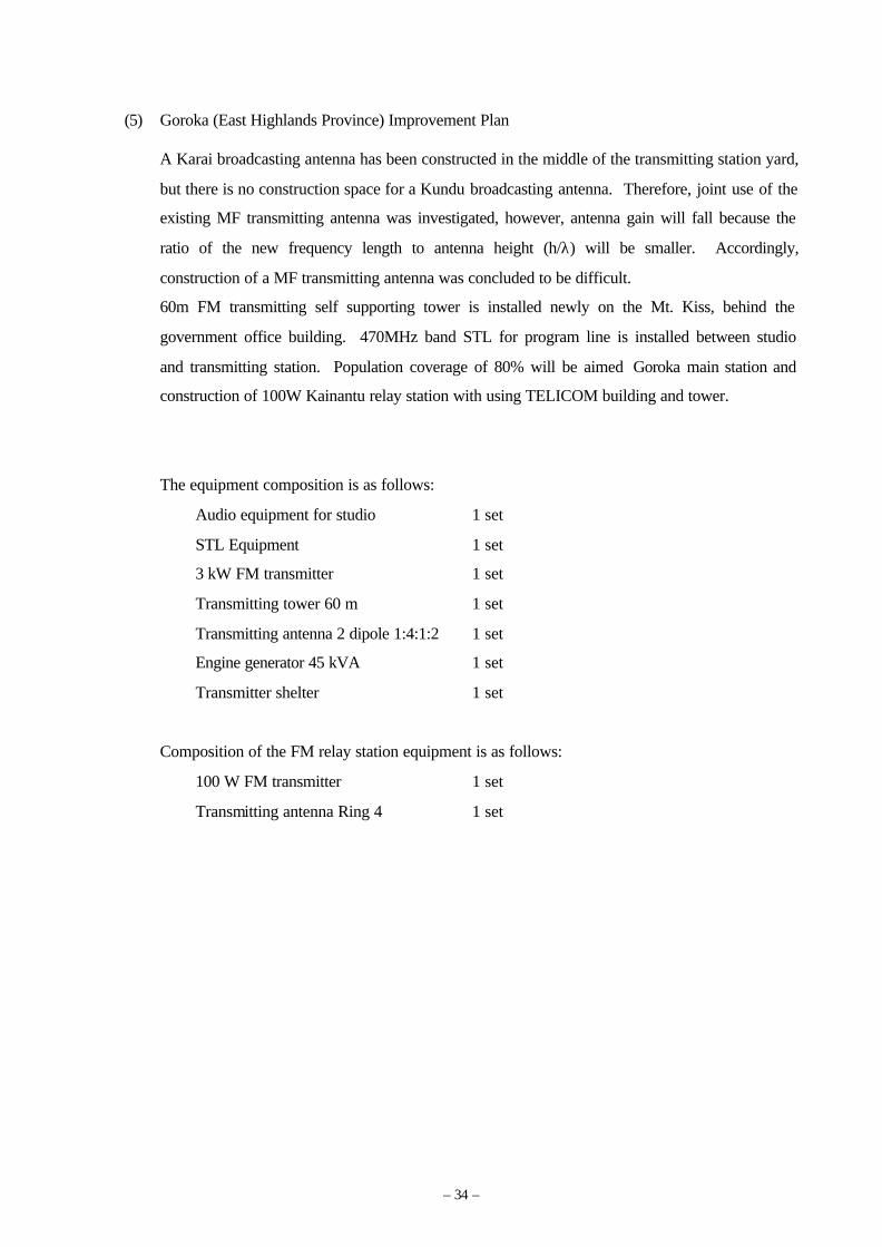
(5) Goroka (East Highlands Province) Improvement Plan
A Karai broadcasting antenna has been constructed in the middle of the transmitting station yard,
but there is no construction space for a Kundu broadcasting antenna. Therefore, joint use of the
existing MF transmitting antenna was investigated, however, antenna gain will fall because the
ratio of the new frequency length to antenna height (h/λ) will be smaller. Accordingly,
construction of a MF transmitting antenna was concluded to be difficult.
60m FM transmitting self supporting tower is installed newly on the Mt. Kiss, behind the
government office building. 470MHz band STL for program line is installed between studio
and transmitting station. Population coverage of 80% will be aimed Goroka main station and
construction of 100W Kainantu relay station with using TELICOM building and tower.
The equipment composition is as follows:
Audio equipment for studio 1 set
STL Equipment 1 set
3 kW FM transmitter 1 set
Transmitting tower 60 m 1 set
Transmitting antenna 2 dipole 1:4:1:2 1 set
Engine generator 45 kVA 1 set
Transmitter shelter 1 set
Composition of the FM relay station equipment is as follows:
100 W FM transmitter 1 set
Transmitting antenna Ring 4 1 set

– 35 –
Table 2-6 Goroka FM Station Equipment
Name of Equipment Quantity Description
A Network Studio Equipment 1 Audio Mixer 1 set With console
Input 12 (mono 4, stereo 8), Prog. output (mono 1, stereo 1)
2 Digital Audio Tape Rec/Rep 1 set DAT format 3 Compact Cassette Tape Rec/Rep 1 set 4 CD Rec/Rep 2 sets Rec: CD-R/CD-RW, Rep: CD/CD-R/CD-RW 5 CD Player 1 set 6 Telephone Pick-up 1 set With Telephone set 7 Audio Monitor Speaker 1 set For mixing 2, for MCR output 2 8 Headphone 2 sets For both ears 9 Audio Distribution Amplifier 1 lot More than 4 output for 1 input, necessary
numbers for system construction
10 Audio Jack Panel 1 lot Necessary numbers for system construction
11 Patch Code 1 set 30cm cable bounded 5 cable × 4, 60cm cable bounded 5 cable × 4
12 Equipment Rack 1 set
13 Equipment Wagon 1 set
14 Microphone 1 set Dynamic type 2, Condenser type 1
15 Microphone Stand 1 set DJ type 1, Desk type 1, Boom type 1
16 Cough Box 2 sets
17 Earphone 2 sets For single ear
18 Microphone Cable 1 set 5m × 3
19 Microphone Connector Panel 1 set With Box
20 On-air Lamp 2 sets
21 Guest Table 1 set
22 Chair for Operation 3 sets For Studio stuff
23 Clock 1 set Wall type, Quartz
– 36 –
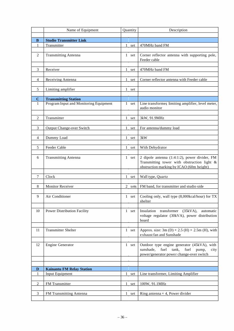
Name of Equipment Quantity Description
B Studio Transmitter Link 1 Transmitter 1 set 470MHz band FM 2 Transmitting Antenna 1 set Corner reflector antenna with supporting pole,
Feeder cable 3 Receiver 1 set 470MHz band FM 4 Receiving Antenna 1 set Corner reflector antenna with Feeder cable 5 Limiting amplifier 1 set
C Transmitting Station 1 Program Input and Monitoring Equipment 1 set Line transformer, limiting amplifier, level meter,
audio monitor 2 Transmitter 1 set 3kW, 91.9MHz 3 Output Change-over Switch 1 set For antenna/dummy load 4 Dummy Load 1 set 3kW 5 Feeder Cable 1 set With Dehydrator 6 Transmitting Antenna 1 set 2 dipole antenna (1:4:1:2), power divider, FM
Transmitting tower with obstruction light & obstruction marking by ICAO (60m height)
7 Clock 1 set Wall type, Quartz 8 Monitor Receiver 2 sets FM band, for transmitter and studio side 9 Air Conditioner 1 set Cooling only, wall type (8,000kcal/hour) for TX
shelter
10 Power Distribution Facility 1 set Insulation transformer (35kVA), automatic voltage regulator (30kVA), power distribution board
11 Transmitter Shelter 1 set Approx. size: 3m (D) × 2.5 (H) × 2.5m (H), with
exhaust fan and Sunshade
12 Engine Generator 1 set Outdoor type engine generator (45kVA), with sunshade, fuel tank, fuel pump, city power/generator power change-over switch
D Kainantu FM Relay Station 1 Input Equipment 1 set Line transformer, Limiting Amplifier 2 FM Transmitter 1 set 100W, 91.1MHz 3 FM Transmitting Antenna 1 set Ring antenna × 4, Power divider
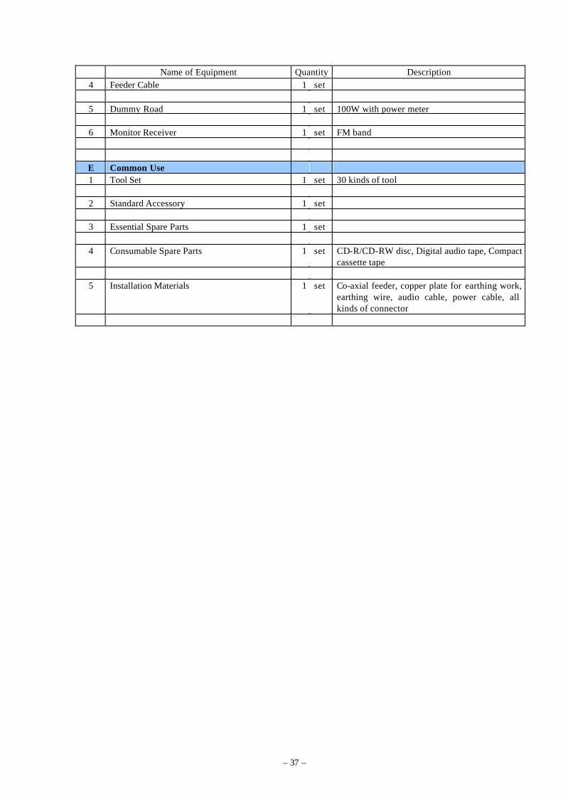
– 37 –
Name of Equipment Quantity Description 4 Feeder Cable 1 set 5 Dummy Road 1 set 100W with power meter 6 Monitor Receiver 1 set FM band
E Common Use 1 Tool Set 1 set 30 kinds of tool 2 Standard Accessory 1 set 3 Essential Spare Parts 1 set 4 Consumable Spare Parts 1 set CD-R/CD-RW disc, Digital audio tape, Compact
cassette tape 5 Installation Materials 1 set Co-axial feeder, copper plate for earthing work,
earthing wire, audio cable, power cable, all kinds of connector

– 38 –
2-2-3 Basic Design Drawing
(1) Mt. Hagen FM Radio Station
• Site Layout of FM Transmitting Station
• Block Diagram of Program Production System
• Block Diagram of Network Studio
• Equipment Layout of Network Studio
• Block Diagram of FM Transmitting Station
• General View of FM Transmitting Antenna
• Schematic Diagram of FM Power Supply System
• Equipment Layout of FM Transmitter Room
• General View of FM Transmitting Tower
(2) Lae MF Radio Station
• Site Layout of MF Transmitting Station
• Block Diagram of Program Production System
• Block Diagram of MF Transmitting Station
• General View of MF Transmitting Antenna
• Schematic Diagram of MF Power Supply System
• Equipment Layout of MF Transmitter Shelter
• Equipment Layout of MF Transmitter Shelter (Section)
(3) Kimbe MF Radio Station
• Site Layout of MF Transmitting Station
• Block Diagram of Program Production System
• Block Diagram of MF Transmitting Station
• General View of MF Transmitting Antenna
• Schematic Diagram of MF Power Supply System
• Equipment Layout of MF Transmitter Shelter
• Equipment Layout of MF Transmitter Shelter (Section)

– 39 –
(4) Vanimo MF Radio Station
• Site Layout of MF Transmitting Station
• Block Diagram of Program Production System
• Block Diagram of Network Studio
• Equipment Layout of Network Studio
• Block Diagram of MF Transmitting Station
• General View of MF Transmitting Antenna
• Schematic Diagram of MF Power Supply System
• Equipment Layout of MF Transmitter Shelter
• Equipment Layout of MF Transmitter Shelter (Section)
(5) Goroka FM Radio Station
• Site Layout of FM Transmitting Station
• Block Diagram of Program Production System
• Block Diagram of Network Studio
• Equipment Layout of Network Studio
• Block Diagram of FM Transmitting Station
• General View of FM Transmitting Antenna
• Schematic Diagram of FM Power Supply System
• Equipment Layout of FM Transmitter Shelter
• Equipment Layout of FM Transmitter Shelter (Section)
• General View of FM Transmitting Tower
(6) Kainantu FM Relay Station
• Site Layout of FM Relay Station
• Block Diagram of FM Relay Station
• General View of FM Transmitting Antenna
• Equipment Layout

– 41 –
Fig. 2-2 Mt. Hagen FM Radio Station Site Layout of FM Transmitting Station S=1:400
New Transmitter Room
Cable Rack
FM Transmitting Tower
Engine Generator, Fuel Tank

Fig. 2-3 Mt. Hagen FM Radio Station Block Diagram of Program Production System
– 43 –
Production Studio
Equipment Karai Program
Kundu Program
New
Existing
(Stereo) (Stereo) To New Transmitter Room
Kundu Program
Network Studio
Equipment
Power Supply
for Studio Equipment
Master Control
Equipment

Fig. 2-4 Mt. Hagen FM Radio Station Block Diagram of Network Studio
– 44 –
(
M
M
M
FU
FU
HYB
TEL
DAT
CCT
CDR
CDP
Network Line
AD
A
CDR
PA L R
Mixing Monitor Speaker
PA L R
MCR Monitor Speaker
MCR
MCR
Stereo Line Monaural Line
Telephone Line
Audio Mixer

Fig. 2-5 Mt. Hagen FM Radio Station Equipment Layout of Network Studio S=1:50
– 45 –
4,6
30
6,320
Guest Table
FU
FU
Chair
Equipment Rack
SP
SP
Equipment Wagon
M
M M
-
Chair
Audio Mixer
Chair

Fig. 2-6 Mt. Hagen FM Radio Station Block Diagram of FM Transmitting Station
– 46 –
PIE FM TX COS
E/G
DHY
A/C
P D B
A V R
ITF COS
New Transmitter Room
Kundu Program
(Stereo)
City Power
415/240V3φ 4W
Feeder Cable
D/L
FM Antenna
60m Transmitting Tower
3kW
45kVA
Sunshade

– 47 –
Fig. 2-7 Mt. Hagen FM Radio Station General View of FM Transmitting Antenna
2,000
A-A’ Plan A’ A
N
FM 2 Dipole Antenna 1:1:1:1
Transmitting Tower
Face A (1 stack)
Face B (1 stack)
Face D (1 stack)
Face C (1 stack)

Fig. 2-8 Mt. Hagen FM Radio Station Schematic Diagram of FM Power Supply System
– 48 –
ITF
E/G
45kVA
E/G
COS ITF
City Power
415/240V 3φ, 4W
AVR
A V 3kW FM TX
35kVA INPUT
(ON/OFF)
(ON/OFF) BY-PASS
INTER LOCK
OV
OV
PIE
Measuring Equipment
Dummy Load
Obstruction Light
DHY
A/C
Exhaust Fan
Utility
AVR/PDB
Spare
30kVA

S=1:50
– 49 –
Fig. 2-9 Mt. Hagen FM Radio Station Equipment Layout of FM Transmitter Room
3kW D/L
3kW FM TX
AVR& PDB
COS
New Transmitter Room
A/C
ITF
PIE
Cable Rack
To Transmitting Antenna
4,700
Record Library
2,80
0
Network Studio

– 50 –
Fig. 2-10 Mt. Hagen FM Radio Station General View of FM Transmitting Tower S=1:400
8,000
45,
000
FM Transmitting Antenna 2 Dipole 1:1:1:1
Cable Rack
Obstruction Light
Obstruction Light
60,
000
15,
000
2,000

– 51 –
Fig. 2-11 Lae MF Radio Station Site Layout of MF Transmitting Station S=1:2,000
Anchor Block
Guy Wire
MF Antenna
100m
ATU
Feeder Cable
Transmitter Shelter, Engine Generator,
Fuel Tank
Radial Earth Field
Existing MF Antenna
Existing TX House
Existing HF Antenna
– 53 –
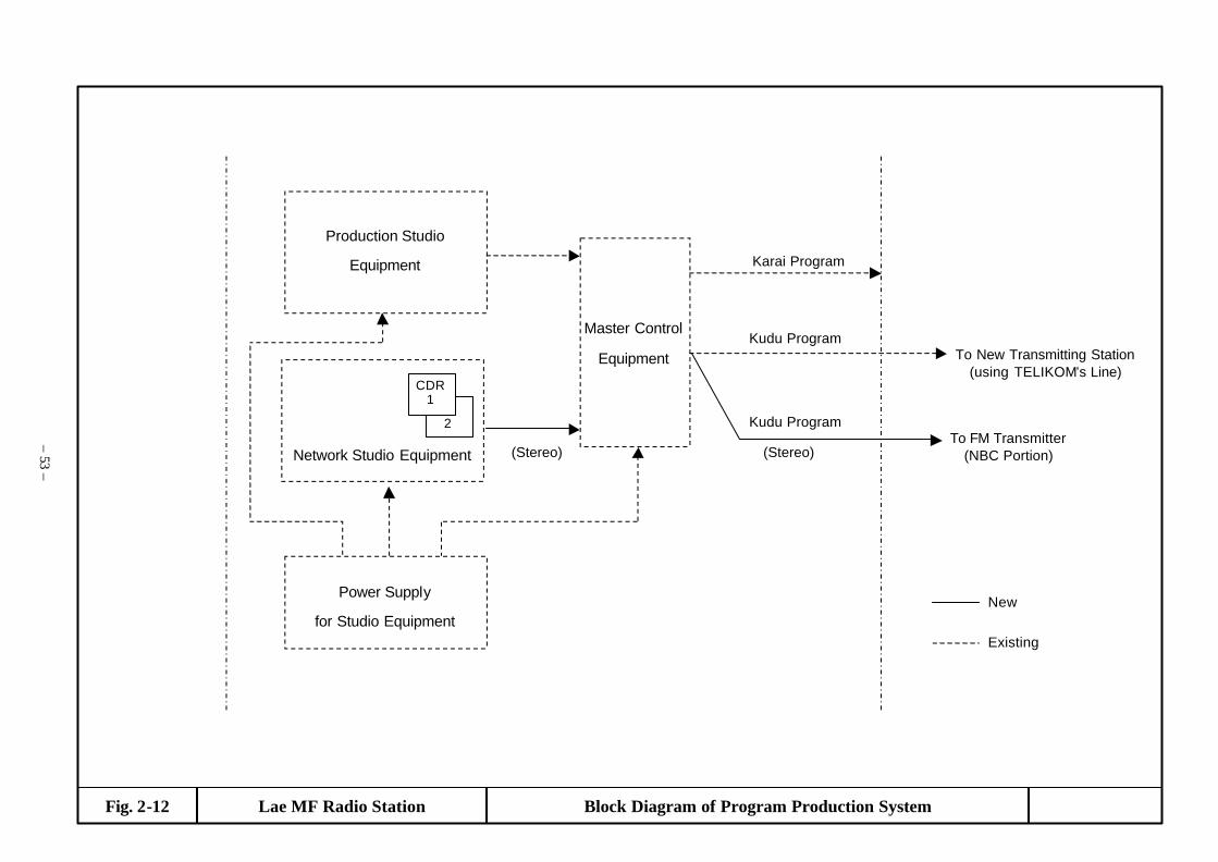
Fig. 2-12 Lae MF Radio Station Block Diagram of Program Production System
Network Studio Equipment
Production Studio
Equipment Karai Program
Kudu Program
New
Existing
(Stereo) (Stereo) To FM Transmitter
(NBC Portion)
Kudu Program
Power Supply
for Studio Equipment
Master Control
Equipment
2
CDR 1
To New Transmitting Station (using TELIKOM’s Line)

– 54 –
Fig. 2-13 Lae MF Radio Station Block Diagram of MF Transmitting Station
PIE MF TX COS
E/G
DHY
A/C
P D B
A V R
ITF COS
Sunshade Transmitter Shelter
Telephone Line
Kundu Program
City Power
ATU Feeder Cable
MF Antenna (H=80m)
Radial Earth D/L
10kW
45kVA
FM RX
415/240V 3φ 4W
FM Lae (NBC’s Portion)

– 55 –
Fig. 2-14 Lae MF Radio Station General View of MF Transmitting Antenna S=1:500
APPROX. 3,000
55,000
GL
20,0
00
20,0
00
Top Loading Mast
Mast Base
Anchor Block
Obstruction Light
Guy Insulator
Obstruction Light
Base Insulator
Less than 0.1λ
Guy Wire
20,0
00
20,0
00
80,0
00
Mast

– 56 –
Fig. 2-15 Lae MF Radio Station Schematic Diagram of MF Power Supply System
ITF
E/G
45kVA
E/G
COS ITF
City Power
AVR
A V 10kW MF TX
45kVA INPUT (ON/OFF)
(ON/OFF) BY-PASS
INTER LOCK
OV
OV
PIE
DHY
A/C
AVR/PDB
415/240V 3φ 4W
40kVA
Measuring Equipment
Dummy Road
Obstruction Light
Exhaust Fan
Utility
Spare

– 57 –
Fig. 2-16 Lae MF Radio Station Equipment Layout of MF Transmitter Shelter S=1:50
A/C A A'
To Antenna
B'
B
APPROX. 6,000
AP
PR
OX
. 2,5
00
10kW D/L
COS
PIE 10kW MF TX
ITF
AVR& PDB
Power Line Program Line
Entrance
Feeder Cable (lay underground)
– 58 –
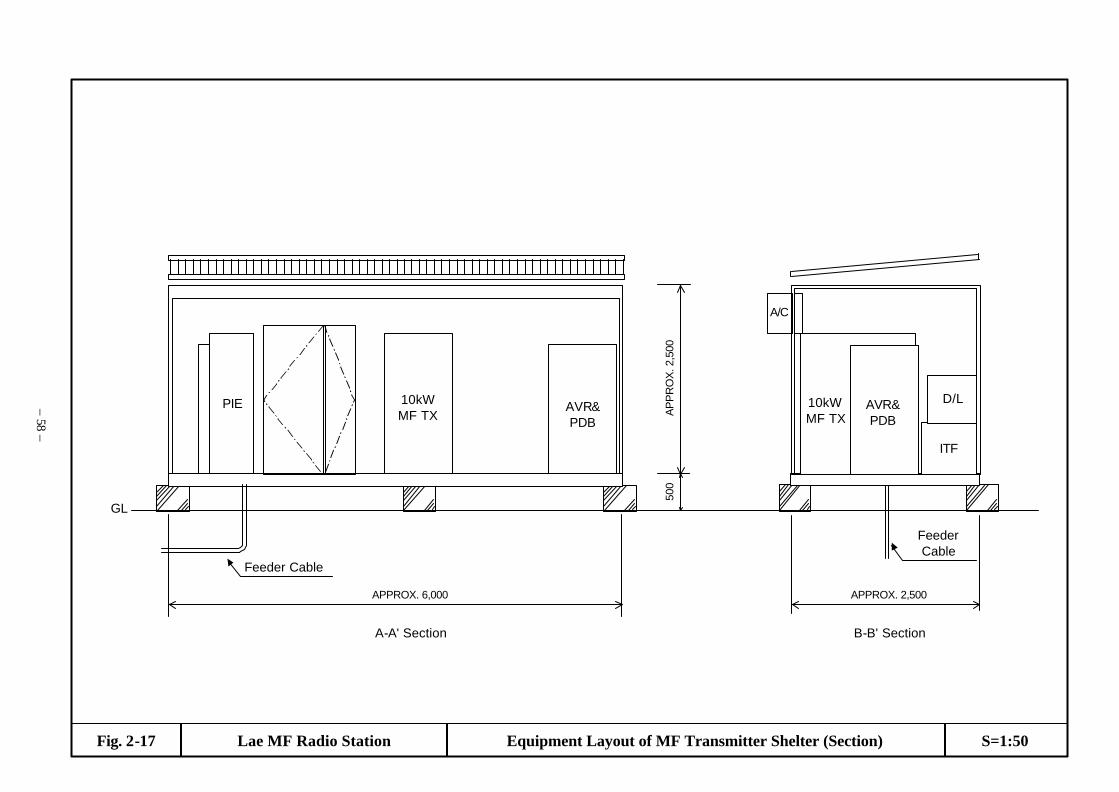
Fig. 2-17 Lae MF Radio Station Equipment Layout of MF Transmitter Shelter (Section) S=1:50
B-B' Section
APPROX. 6,000
AP
PR
OX
. 2,5
00
A/C
GL
A-A' Section
PIE AVR& PDB
10kW MF TX
APPROX. 2,500
500
AVR& PDB
10kW MF TX
D/L
ITF
Feeder Cable
Feeder Cable

− 59 −
Fig. 2-18 Kimbe MF Radio Station Site Layout of MF Tranmitting Station S=1:2,000
Existing TX House
Existing HF Antenna
Transmitter Shelter, Engine Generator,
Fuel Tank
Radial Earth Field
MF Antenna
Anchor Block Guy Wire
ATU
Feeder Cable
To H
oski
nsTo
Tal
asea

− 61 −
Fig. 2-19 Kimbe MF Radio Station Block Diagram of Program Production System
Production Studio
Equipment
Karai Program
Kundu Program
New
Existing
To New Transmitting
Station Kundu Program
Network Studio Equipment
Power Supply
for Studio Equipment
Master Control
Equipment
2
CDR 1
TELIKOM’s Line
STL
TX

− 62 −
Fig. 2-20 Kimbe MF Radio Station Block Diagram of MF Transmitting Station
PIE MF TX COS
E/G
DHY
A/C
P D B
A V R
ITF COS
Sunshade Transmitter Shelter
Telephone Line
Kundu Program
City Power
ATU Feeder Cable
MF Antenna (H=80m)
Radial Earth D/L
10kW
45kVA
STL RX
415/240V 3φ 4W
– 63 –
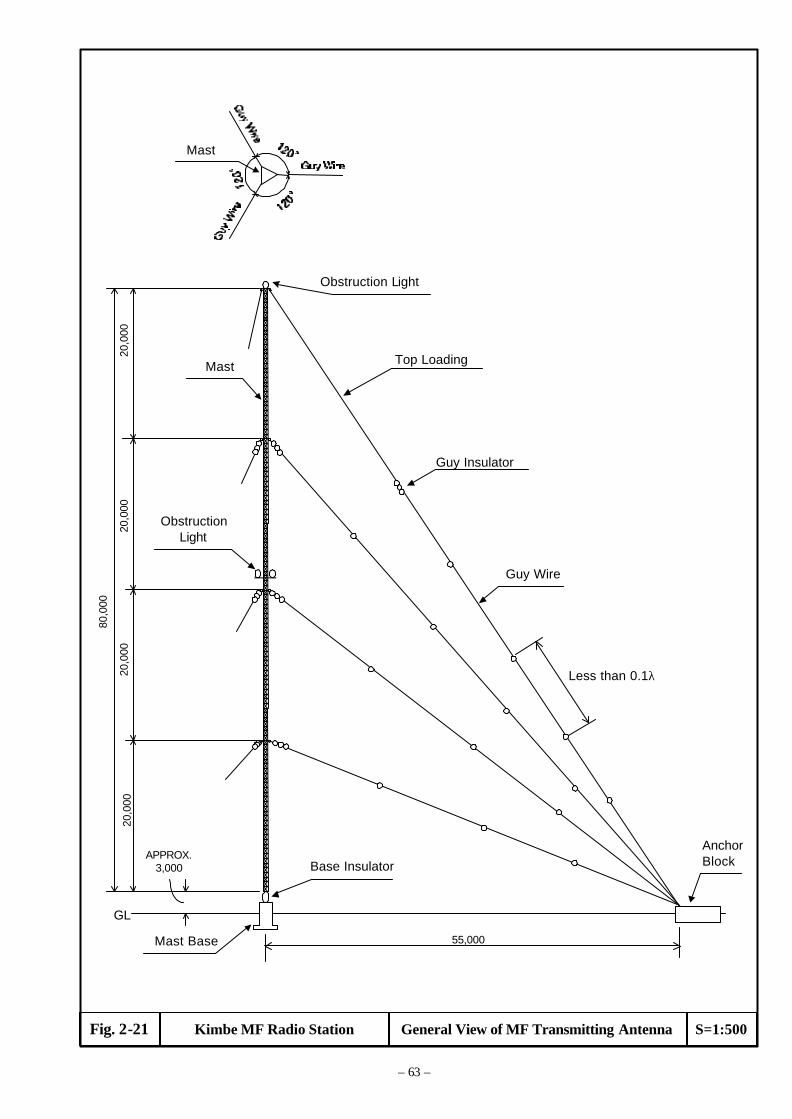
Fig. 2-21 Kimbe MF Radio Station General View of MF Transmitting Antenna S=1:500
APPROX. 3,000
55,000
GL
20,0
00
20,0
00
Top Loading Mast
Mast Base
Anchor Block
Obstruction Light
Guy Insulator
Obstruction Light
Base Insulator
Less than 0.1λ
Guy Wire
20,0
00
20,0
00
80,0
00
Mast

− 64 −
Fig. 2-22 Kimbe MF Radio Station Schematic Diagram of MF Power Supply System
ITF
E/G
45kVA
E/G
COS ITF
AVR
A V 10kW MF TX
45kVA INPUT (ON/OFF)
(ON/OFF) BY-PASS
OV
OV
PIE
A/C
AVR/PDB
415/240V 3φ 4W
City Power INTER LOCK
DHY 40kVA
Measuring Equipment
Dummy Load
Obstruction Light
Exhaust Fan
Utility
Spare

− 65 −
Fig. 2-23 Kimbe MF Radio Station Equipment Layout of MF Transmitter Shelter S=1:50
A/C A A'
To Antenna
B'
B
APPROX. 6,000
AP
PR
OX
. 2,5
00
10kW D/L
COS
PIE 10kW MF TX
ITF
AVR& PDB
Power Line Program Line
Entrance Feeder Cable
(lay underground)

− 66 −
Fig. 2-24 Kimbe MF Radio Station Equipment Layout of MF Transmitter Shelter (Section) S=1:50
B-B' Section
APPROX. 6,000
AP
PR
OX
. 2,5
00
A/C
GL
A-A' Section
PIE AVR& PDB
10kW MF TX
APPROX. 2,500
500
AVR& PDB
10kW MF TX
D/L
ITF
Feeder Cable
Feeder Cable

– 67 –
Fig. 2-25 Vanimo MF Radio Station Site Layout of MF Transmitting Station S=1:2,000
Radial Earth Field
Anchor Block
Guy Wire
MF Antenna
ATU
Feeder Cable
Transmitter Shelter, Engine Generator,
Fuel Tank
Existing HF Antenna
Existing MF Antenna
Existing TX House

– 69 –
Fig. 2-26 Vanimo MF Radio Station Block Diagram of Program Production System
Production Studio
Equipment
Karai Program
Kundu Program
New
Existing
To New Transmitting Station Kundu
Program
Network Studio
Equipment
Power Supply
for Studio Equipment
Master Control
Equipment TELIKOM’s
Line
STL
TX

– 70 –
Fig. 2-27 Vanimo MF Radio Station Block Diagram of Network Studio
(
M
M
M
FU
FU
HYB
TEL
DAT
CCT
CDR
CDP
Network Line
AD
A
CDR
PA L R
Mixing Monitor Speaker
PA L R
MCR Monitor Speaker
MCR
MCR
Stereo Line Monaural Line
Telephone Line
Audio Mixer
– 71 –
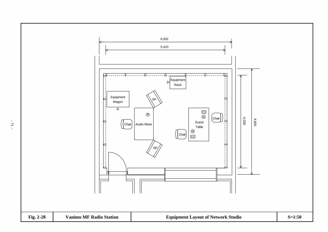
Fig. 2-28 Vanimo MF Radio Station Equipment Layout of Network Studio S=1:50
Guest Table
FU
FU
Chair
Equipment Rack
SP
SP
Equipment Wagon
M
M M
Audio Mixer - -
4,800
4,208
6,002
5,410
Chair
Chair

– 72 –
Fig. 2-29 Vanimo MF Radio Station Block Diagram of MF Transmitting Station
PIE MF TX COS
E/G
DHY
A/C
P D B
A V R
ITF COS
ATU
D/L
10kW
45kVA
STL RX
415/240V 3φ 4W
Sunshade Transmitter Shelter
Telephone Line
Kundu Program
City Power
Feeder Cable
MF Antenna (H=80m)
Radial Earth

– 73 –
Fig. 2-30 Vanimo MF Radio Station General View of MF Transmitting Antenna S=1:500
APPROX. 3,000
55,000
GL
20,0
00
20,0
00
Top Loading Mast
Mast Base
Anchor Block
Obstruction Light
Guy Insulator
Obstruction Light
Base Insulator
Less than 0.1λ
Guy Wire
20,0
00
20,0
00
80,0
00
Mast

– 74 –
Fig. 2-31 Vanimo MF Radio Station Schematic Diagram of MF Power Supply System
ITF
E/G
45kVA
E/G
COS ITF
AVR
A V 10kW MF TX
45kVA INPUT
(ON/OFF)
(ON/OFF) BY-PASS
OV
OV
PIE
AVR/PDB
415/240V 3φ 4W
A/C
City Power INTER LOCK
DHY 40kVA
Measuring Equipment
Dummy Load
Obstruction Light
Exhaust Fan
Utility
Spare

– 75 –
Fig. 2-32 Vanimo MF Radio Station Equipment Layout of MF Transmitter Shelter S=1:50
A/C A A'
To Antenna
B'
B
APPROX. 6,000
AP
PR
OX
. 2,5
00
10kW D/L
COS
PIE 10kW MF TX
ITF
AVR& PDB
Power Line Program Line
Entrance
Feeder Cable (lay underground)
– 76 –
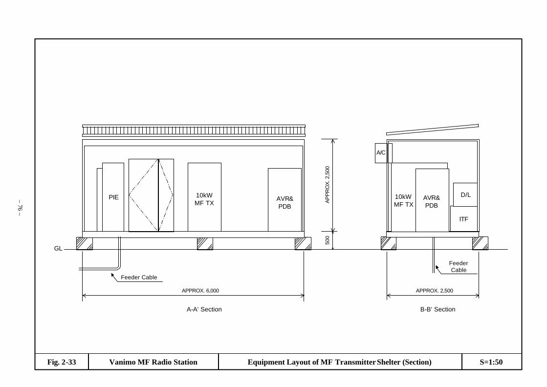
Fig. 2-33 Vanimo MF Radio Station Equipment Layout of MF Transmitter Shelter (Section) S=1:50
B-B' Section
APPROX. 6,000
AP
PR
OX
. 2,5
00
A/C
GL
A-A' Section
PIE AVR& PDB
10kW MF TX
APPROX. 2,500
500
AVR& PDB
10kW MF TX
D/L
ITF
Feeder Cable
Feeder Cable

– 77 –
Fig. 2-34 Goroka FM Radio Station Site Layout of FM Transmitting Station S=1:500
FM Transmitting Tower
Transmitter Shelter
Engine Generator, Fuel Tank
Cable Rack

– 79 –
Fig. 2-35 Goroka FM Radio Station Block Diagram of Program Production System
(Stereo)
Production Studio
Equipment Karai Program
Kundu Program
New
Existing
Kundu Program Network Studio
Equipment
Power Supply
for Studio Equipment
Master Control
Equipment To Kainantu FM Relay Station (using TELICOM’s Line)
STL
(Stereo)
To Transmitter Shelter TX

– 80 –
Fig. 2-36 Goroka FM Radio Station Block Diagram of Network Studio
(
M
M
M
FU
FU
HYB
TEL
DAT
CCT
CDR
CDP
Network Line
AD
A
CDR
PA L R
Mixing Monitor Speaker
PA L R
MCR Monitor Speaker
MCR
MCR
Stereo Line Monaural Line
Telephone Line
Audio Mixer

– 81 –
Fig. 2-37 Goroka FM Radio Station Equipment Layout of Network Studio S=1:50
Chair Guest Table
FU
FU
Chair
Equipment Rack
SP
SP
Equipment Wagon
M
M M
Chair
Audio Mixer
4,800
4,208
6,002
5,410

– 82 –
Fig. 2-38 Goroka FM Radio Station Block Diagram of FM Transmitting Station
COS
E/G
DHY
A/C
P D B
A V R
ITF COS
D/L
45kVA
415/240V 3φ 4W
City Power
Feeder Cable
FM Antenna
60m Transmitting Tower
Sunshade New Transmitter Room
FM TX
3kW STL RX
PIE

– 83 –
Fig. 2-39 Goroka FM Radio Station General View of FM Transmitting Antenna
A-A’ plan
2,000
AP
PR
OX
. 3,0
00
A’ A
N
Face D (2 stacks)
Transmitting Tower
FM 2 Dipole Antenna 1:4:1:2
Face A (1 stack)
Face C (1 stack)
Face B (4 stacks)
AP
PR
OX
. 3,0
00
AP
PR
OX
. 3,0
00

– 84 –
Fig. 2-40 Goroka FM Radio Station Schematic Diagram of FM Power Supply System
ITF
E/G
45kVA
E/G
COS ITF
City Power
415/240V3φ, 4W AVR
A V 3kW FM TX
35kVA INPUT
(ON/OFF)
(ON/OFF) BY-PASS
INTER LOCK
OV
OV
PIE
Measuring Equipment
Dummy Load
Obstruction Light
DHY
A/C
Exhaust Fan
Utility
AVR/PDB
Spare
30kVA

– 85 –
Fig. 2-41 Goroka FM Radio Station Equipment Layout of FM Transmitter Shelter S=1:50
A/C
A A'
B'
B
APPROX. 3,000
AP
PR
OX
. 2,5
00
3kW D/L
3kW FM TX
ITF
AVR& PDB
Entrance
COS
Cable Rack
To Antenna
PIE

– 86 –
Fig. 2-42 Goroka FM Radio Station Equipment Layout of FM Transmitter Shelter (Section) S=1:50
B-B' Section
APPROX. 3,000 APPROX. 2,500
AP
PR
OX
. 2,5
00
A/C
GL
A-A' Section
PIE 3kW FM TX
ITF
AVR& PDB
3kW FM TX
AVR&
PDB
COS
500
PIE
ITF
– 87 –
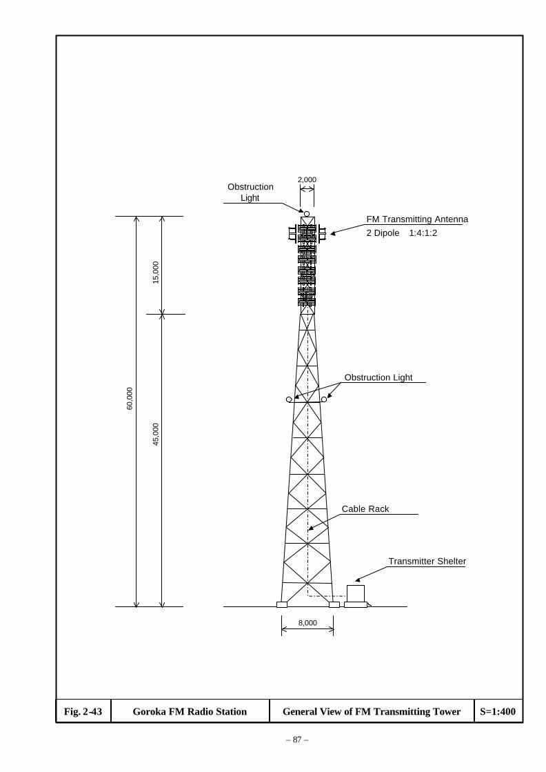
Fig. 2-43 Goroka FM Radio Station General View of FM Transmitting Tower S=1:400
8,000
45,
000
FM Transmitting Antenna 2 Dipole 1:4:1:2
Cable Rack
Obstruction Light
Obstruction Light
60,
000
15,
000
2,000
Transmitter Shelter

– 88 –
Fig. 2-44 Kainantu FM Relay Station Site Layout of FM Relay Station S=1:100
4,60
0
Installation Area for FM Transmitter
2,500
TELICOM Repeater Station
TELICOM Tower
H=30m
100 100 9,250 100
2,00
0
1,300
3,000
700
700
6,30
0
6,300
Cable Rack
(Existing)

– 89 –
Fig. 2-45 Kainantu FM Relay Station Block Diagram of FM Relay Station
AC 240V, 1φ, 50Hz
Transmitter Floor (inside of TELICOM Repeater Station)
Uninterrupted Power Supply
Feeder Cable
FM Antenna
TELICOM Tower
TELIKOM’s Line
Kundu Program
FM TX
100W
LIM
Input Equipment
LT

– 90 –
Fig. 2-46 Kainantu FM Relay Station General View of FM Transmitting Antenna S=1:200
TELICOM Repeater Station
A’ A
4,00
0 26
,000
30,0
00
Cable Rack
3,000
3,000 6,300
700×700
TELICOM Tower
FM Transmitting Antenna Ring Antenna 4 stacks
FM Transmitting Antenna
TELICOM Tower
A-A’ Plan

– 91 –
Fig. 2-47 Kainantu FM Relay Station Equipment Layout S=1:50
9,520
4,60
0
610x610
1,200x800
840x620
2,450 1,460 1,460
1,340
750x650
800x1680
1,030
600x400
310
1,310x680
FM TX
100W
Installation Area
390
680
2,34
0
380
760
2,00
0
1,300

– 92 –
2-2-4 Implementation Plan
2-2-4-1 Implementation Policy
(1) Consideration of Works Progress in Six Sites
The Project entails installation of three MF transmitting stations in coastal areas, and three FM
transmitting stations (including a repeater station) in highland areas. Two or three working
parties shall simultaneously implement the works. The distance between the FM transmitting
station construction sites in Goroka and Mt. Hagen is approximately 180 km, and overland
transportation from Lae is available. However, the MF station sites of Vanimo and Lae are
separated by approximately 800 km, and the sites of Lae and Kimbe (New Britain Island) by
approximately 390 km. Not only are these sites widely dispersed, but also it is necessary to rely
on marine transportation from Lae.
In consideration of these special circumstances, it is important to formulate detailed
implementation plan, transportation plan and process schedule, and consultant to take an
initiative in securing coordination and cooperation with the client and contractor.
(2) Procurement of Construction Materials and Skilled Workers
As mentioned above, the dispersed location of construction sites, make it very difficult to procure
not only high quality local construction contractors, but also skilled workers such as formwork
carpenters, electrical engineers and antenna installation workers, and construction machines and
materials.
Accordingly, it will be necessary to either contract works out to established contractors based on
Port Moresby, or to permanently employ skilled workers and dispatch them to the sites.
(3) Dispatch of Technical Expert
In Papua New Guinea, it is very difficult to secure personnel for positions that require very
special technology, for example, installation of broadcasting equipment, construction of
transmitting towers and antennas, and so on. Therefore, concerning execution of these works,
these personnel shall be dispatched from Japan in order to implement work while at the same
time transferring technology to the local technicians.

– 93 –
2-2-4-2 Implementation Conditions
(1) Consideration of Natural Conditions
Natural conditions on the five sites are various, and even the rainy and dry seasons are different.
Therefore, it is necessary to formulate the works schedule in consideration of these conditions.
MF antenna installation works will be carried out in coastal and island areas for the transmitting
antennas and radial earths, etc.
In highland areas, FM broadcasting will be adopted, however, it will be appropriate to implement
steel tower works in the dry season from May to June.
Concerning humidity, relative humidity in both morning and afternoon is at between 70-90%
throughout the year in coastal areas. In highland areas, on the other hand, relative humidity
changes greatly from 60% to 90% between the morning and afternoon. As for island areas,
humidity changes between morning and afternoon according to the season, however, it is
generally stable at between 75-85%.
Since average temperatures on the Project sites are high, tropical region specifications shall be
adopted in design of Project equipment. Concerning transmitter shelters, specifications that take
air tightness and temperature control into account shall be adopted.
Moreover, since average monthly rainfall of 640 mm has been recorded in coastal areas during
the rainy season, the effects of heavy rainfall shall be countered by installing transmitter shelters
at GL +800 mm and so on.
(2) Construction Machine, Materials and Labor Procurement Plan
Only basic materials can be procured at the project sites. Since heavy construction machines
and special materials can only be obtained in the capital city of Port Moresby and the second city
of Lae, it will be necessary to implement preliminary survey and collect information as well as
procure skilled workers and conduct site preparations, etc.
– 94 –
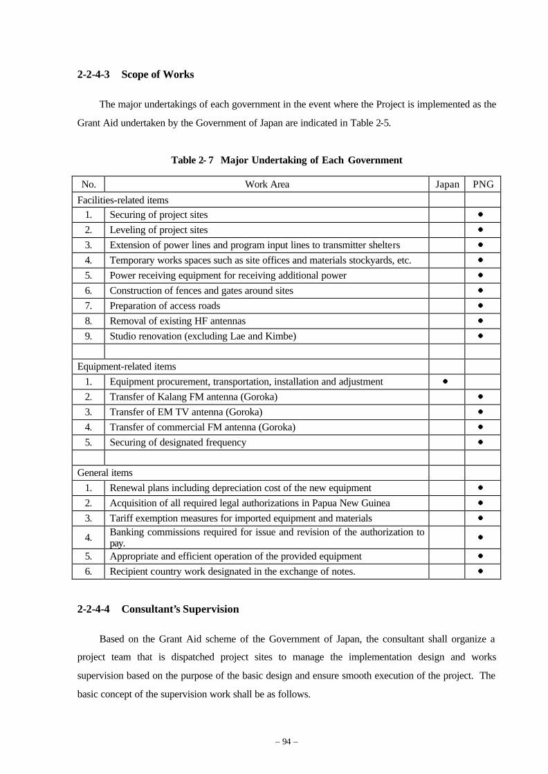
2-2-4-3 Scope of Works
The major undertakings of each government in the event where the Project is implemented as the
Grant Aid undertaken by the Government of Japan are indicated in Table 2-5.
Table 2- 7 Major Undertaking of Each Government
No. Work Area Japan PNG
Facilities-related items 1. Securing of project sites
2. Leveling of project sites
3. Extension of power lines and program input lines to transmitter shelters
4. Temporary works spaces such as site offices and materials stockyards, etc.
5. Power receiving equipment for receiving additional power
6. Construction of fences and gates around sites
7. Preparation of access roads
8. Removal of existing HF antennas
9. Studio renovation (excluding Lae and Kimbe)
Equipment-related items
1. Equipment procurement, transportation, installation and adjustment
2. Transfer of Kalang FM antenna (Goroka)
3. Transfer of EM TV antenna (Goroka)
4. Transfer of commercial FM antenna (Goroka)
5. Securing of designated frequency
General items
1. Renewal plans including depreciation cost of the new equipment
2. Acquisition of all required legal authorizations in Papua New Guinea
3. Tariff exemption measures for imported equipment and materials
4. Banking commissions required for issue and revision of the authorization to pay.
5. Appropriate and efficient operation of the provided equipment
6. Recipient country work designated in the exchange of notes.
2-2-4-4 Consultant’s Supervision
Based on the Grant Aid scheme of the Government of Japan, the consultant shall organize a
project team that is dispatched project sites to manage the implementation design and works
supervision based on the purpose of the basic design and ensure smooth execution of the project. The
basic concept of the supervision work shall be as follows.

– 95 –
(1) Basic Concept of Supervision
To maintain close communications with agencies and officials in both countries and aim for
Project completion based on the implementation schedule.
• offer appropriate guidance and advice to related officials to ensure that equipment is
installed meeting the project specifications.
• carry out enough guidance to NBC on operation and maintenance of equipment.
• offer appropriate guidance and advice on equipment and maintenance of after completion of
installation.
(2) Contents of Consultant’s Supervision
• Contract related work
Consultant shall prepare and carry out ① tender document, ② handling of bidders from
announcement of tender through to opening of bids, ③ assessment of tenders and selection
of contractor, ④ holding of contract negotiations, and ⑤ witnessing of the contract, etc.
and report on the progress and results of such as work to the client at appropriate stage.
• Confirmation and inspection of items submitted by equipment suppliers
The consultant shall confirm the contents of shop drawings and materials samples submitted
by equipment suppliers, and implement inspections where necessary.
• Confirmation of Implementation Plan
The consultant shall examine and confirm the implementation plan such as work schedule
submitted by contractor, and offer guidance to contractor, and submit report to the
implementing agency.
• Cooperation Regarding Payment Approval Procedure
Concerning contract fees to be paid to contractors, the consultant shall examine all requests
for payment, etc. that are submitted by the contractor, and issue the necessary certificates.
• Witnessing of Inspections
Consultant shall inspect the quality and completion work in each installation stage, and also,
witness for all test, including inspections and final inspection that are implemented on the
contract.
Also, consultant reports all necessary items concerning work’s progress payment procedures
and completion and handing over to related agencies in the Government of Japan side.

– 96 –
The consultant work shall be completed after obtaining approval from the client.
(3) Supervision Staffing Plan
Although the Project is an equipment supply, since it deals with radio transmitting stations, works
include numerous foundation and installation works for steel towers, antennas, transmitter
shelters and engines generator, etc. Moreover, the said works shall be completed efficiently
with uniform quality at five different sites scattered around PNG. Lae, one of five sites, is the
second largest city in PNG, so it will be possible to procure subcontractors, laborers and materials,
etc., however, remaining four sites will be in a much more difficult condition.
The consultant will monitor the overall execution situation while keeping close communications
with contractor and local government officials, and patrol between five construction sites to
ensure the quality of works according to the overall implementing schedule.
Accordingly, consultants have been assigned so that one supervisor is stationed at each site to
oversee foundation works and steel tower and antenna installation works, and one more
supervisor is assigned to oversee transmitters, installation of studio equipment and program
transmission equipment according to the stage of works. However, since works will be
simultaneously done at five sites at peak times, the plan has been compiled so that one supervisor
for facilities and one supervisor for equipment shall be assigned timely to sites as required.
Requirement for the selection of the supervision staff in both fields shall be possession abundant
experience, appropriate technical judgment, wide perspective, and coordinating capacity.
2-2-4-5 Quality Control Plan
The consultant shall carry out quality control in the Project implementation stage based on the
purport of the basic design. Quality control here is defined as ‘the system of means for economically
producing goods and services that comply with buyer requirements’, and this definition shall be
adopted as the basic line of thinking for Project implementation.
The consultant shall implement the following quality control work.
(1) Quality Control Plan for Installation Work
1) Quality control items for concrete work shall be as follows:
• Cement: confirm quality by carefully checking plant shipping certificates and the
contents of plant work result.

– 97 –
• Decision of mixing proportions:
carry out trial kneading and determine the mix proportions
of kneaded materials to ensure that the designated strength
and workability are secured.
• Concrete strength: consign a public or private test agency to carry out
compression testing when the concrete is 1 and 4 weeks
old.
• Concrete placement: check that the required workability is secured before
placement by inspecting slump and airflow.
• Curing after placement: confirm that appropriate curing by water sprinkling is
carried out after placement.
2) Imported reinforcing bars can be procured in PNG, however, the manufacturer ’s ‘Mill
Sheet’ guaranteeing quality is frequently not attached. Therefore, the strength of bars shall
be confirmed by consigning tensile testing to public or private test agencies.
3) Concerning steel tower and MF antenna materia ls, the quality and strength of materials, bolt
strength and precision, etc. shall be confirmed based on Mill Sheets and materials presented
by manufacturers.
4) Concerning transmitter shelters, working drawings presented before fabrication shall be
checked, and inspections shall be carried out at the fabricating factory.
(2) Quality Control Plan for Equipment and Materials Procurement
1) To review the working drawings, shop drawings, technical materials and samples, etc.
submitted by the contractors, and make sure that contents conform with the plans and
standards, etc. contained on design drawings and specifications.
2) Before shipping materials and equipment from factories, consign pre-shipping inspections
to a reputable inspection agency:
• Checking of the contract equipment and materials list with shipping documents,
• Checking of shipping documents with actual equipment and materials,
• Issue of inspection certificates.

– 98 –
2-2-4-6 Procurement Plan
(1) Materials Procurement Plan
Procurement destinations in Japan’s Grant Aid are limited as a rule to Japan or the recipient
country, however, procurement considering after service in PNG is desirable.
Foundation works materials will be procured in Papua New Guinea. The following table gives
an outline of materials procurement divisions.
Source Materials
PNG Third Country Japan
Reason for Selection
Sand ü Supply of mountain sand is possible.
Cement ü Local products have a proven quality record.
Reinforcing bars ü Local products have a proven quality record.
Steel-frame ü Securing of quality and performance and certainty of supply
Timber ü There are no problems in terms of quality.
Steel tower ü Securing of quality and performance and certainty of supply
Transmitter shelter ü Securing of quality and performance and certainty of supply
Transformer ü Securing of quality and performance and certainty of supply
Main panel ü Securing of quality and performance and certainty of supply
Distribution panel ü Securing of quality and performance and certainty of supply
Engine generator ü After-sales service
Oil tank ü Securing of quality and performance and certainty of supply
Power line and cable ü Securing of quality and performance and certainty of supply
(2) Equipment Procurement Plan
Equipment shall be procured in Papua New Guinea or Japan, however, since it is not possible to
obtain appropriate performance guarantees, quality assurance and after-sales service in Papua
New Guinea, Japanese products will make up the bulk of equipment.
Since almost existing equipment of NBC are made in Japan, they have a good reputation for high
levels of performance, quality and after service and are easy to use. So, NBC is strongly
requesting that Japanese equipment shall be supplied.

– 99 –
However, the Japanese market for transmitters has finished shifting over to solid-state
transmitters, and shipments of FM transmitters are almost non-existent as there are still no
direction for terrestrial digital sound broadcasting. Therefore, transmitter manufacturers no
longer produce FM transmitters.
In these circumstances, since it is not advisable in terms of economy and time to persist on
Japanese products, procurement from third countries shall also be considered for FM transmitters
and peripheral equipment.
(3) Equipment and Materials Transportation Plan
The first landing port for Project equipment and materials will be Lae Port in Morobe Province.
To Kimbe, equipment and materials can be transported along the coast by small boat from Lae to
Kimbe. Concerning transportation to Vanimo, since landing facilities at this port are not
completed, equipment and materials shall be landed at Wewak by small boat from Lae and
transported overland to Vanimo Station.
Transportation lead-times from Japan to the Project sites are as follows.
• Lae (Morobe Province) Approx. 45 days
• Goroka (East Highlands Province) Approx. 50 days
• Mt. Hagen (West Highlands Province) Approx. 50 days
• Vanimo (West Sepik Province) Approx. 50 days
• Kimbe (West New Britain Province) Approx. 60 days
2-2-4-7 Implementation Schedule
The Project implementation schedule is as indicated on the following page.
It is estimated that 15 months will be required from the consultant contract through to completion
and handing-over of facilities and equipment
1) Detail design and tendering : 4 months
2) Procurement and installation of Equipment : 11 months

– 100 –
Table 2- 8 Work Implementation Schedule
1 2 3 4 5 6 7 8 9 10 11 12
Implem
entation D
esign and Tendering
Procurem
ent and Installation of Equipm
ent
Legend: Work in Japan Work in PNG
(Final Confirmation of Project)
(Preparation of Tender Documents)
(Approval of Tender Documents)
(Tender Work)
[ Lae ]
[ Vanimo ]
[ Kimbe ]
[ Mt. Hagen ]
[ Goroka ]
Acceptance Test and Handing Over
gennchi
(Total 4 months)
Factory Inspection
(Total 11 months)
Transport (Steel Tower& MF Antenna)
Transport (Equipment)
Equipment Manufacturing (Steel Tower& MF Antenna)
Equipment Manufacturing (Equipment)
Pile Works
Foundation
Erection Woks
Equipment & Material Works
gennchi Foundation
Erection Woks
Equipment & Material Works
Foundation
Erection Woks
Equipment & Material Works
Foundation
Erection Woks
Equipment & Material Works
Foundation
Erection Woks
Equipment & Material Works

– 101 –
2-3 Obligations of Recipient Country
Obligations of the Papua New Guinea side in the event where the Project is implemented under
the Grant Aid scheme of the Government of Japan are as follows.
(1) Securing of Project Sites
Land problems frequently develop into serious disputes in Papua New Guinea. Some of the
Project sites in this project are on existing stations, however, it is necessary to confirm newly
official letters for the sites.
Project Site Notes
Mt. Hagen
(West Highlands Province) NBC land
Lae
(Morobe Province)
None in particular
Kimbe
(West-New Britain
province)
The provincial government has given verbal permission concerning
extension of the NBC development period for the MF antenna
construction site, however, written permission is required.
Vanimo
(West Sepik Province)
A project road is designated within the NBC land. Revision of the
project road route will be confirmed in writing.
Goroka
(East Highlands Province)
Mt. Kiss behind the government offices building has been newly
designated. Corroboration will be required.
Kainantu relay station
(Goroka)
Lease the TELICOM satellite station building and steel tower.
Permission is required to use the building and steel tower.
(2) Preparation of Project Sites
Leveling of construction sites shall be completed before the start of site works in the Project.
(3) Temporary Works Space for Site Offices and Stockyards, etc.
Temporary office sites and materials stockyards shall be secured on each transmitter site.
(4) Power Receiving Equipment for Additional Power
It is planned that Vanimo (West Sepik Province) will jointly use a HF transmitter for the time
being. In this case, power supply to the new facility will be added on existing power receiving
facility.

– 102 –
(5) Site Fences and Gates
There is a possibility that the Project transmitting stations will be unmanned at night due to
reductions of maintenance staff. In order to prevent theft and sabotage of equipment, fences and
gates around the stations must provide adequate protection.
(6) Preparation of Access Roads
It is forecast that equipment works will take place in the rainy season. In order to promote
smooth works progress, the foundations of roads leading from main roads to Project sites shall be
consolidated with gravel, etc.
(7) Removal of Existing HF Antennas
Since the HF antenna poles that will no longer be needed at Kimbe, Lae and Vanimo will
obstruction MF propagation, they shall be removed.
(8) Acquisition of All Legal Authorizations in Papua New Guinea
In Papua New Guinea, decentralization has been in progress since 1996 and revisions are
expected in all tax systems. NBC must meet with officials of the Ministry of Information,
Ministry of Finance and Ministry of Construction, etc. and make sure that all necessary
procedures concerning building office registration, project tax, income tax and building permits,
which could potentially hinder the Project, are complete by the start of the works.
(9) Tariff Exemption Measures for Import of Equipment and Construction Materials
Project equipment and materials will be trans-shipped via Lae to Kimbe and Vanimo. They will
also be transported to Goroka and Mt. Hagen in highland regions.
NBC shall conduct prior explanations to related ministries and agencies and promote the Project
to ensure that no problems occur in transportation at transit points.
(10) Bank Commissions Concerning Issue and Revision of Authorization to Pay
The authorization to pay will be issued according to banking arrangement between the
representative bank on the Papua New Guinea side and the representative bank on the Japan side.
The bank commissions amount to around 0.1% of the total grant and must be prepared at the
expense of the local side.

– 103 –
(11) Appropriate and Efficient Operation of Supplied Facilities and Equipment
The local side must save appropriate funds to cover equipment operation and maintenance
expenses including depreciation costs, so that it is able to renew equipment at its own expense
following the stable operation term after installation.
(12) Execution of Other Work Prescribed in the Exchanged Notes
See Appendices 4 “Minutes of Discussion dated November 1, 2002”.
(13) Cost estimate of works to be prepared by PNG side
Total amount of the cost to be prepared by PNG side is 495,000kina.
Breakdown of the cost is as follows.
1) PNG Cost Burden: 495,000 kina (15,300,000 yen)
① Leveling of Project sites: 130,000 kina (4,000,000 yen)
② Gate and fence building and renovation of buildings: 175,000 kina (5,500,000 yen)
③ Laying of power lines to transmitter rooms: 125,000 kina (3,800,000 yen)
④ Laying of program line to transmitter rooms: 65,000 kina (2,000,000 yen)
Above cost have been estimated by NBC.
2) Execution period: implementation design and execution and procurement are as
indicated in the Work Implementation Schedule.

– 104 –
2-4 Project Operation Plan
2-4-1 Operation and Maintenance for Kundu Broadcasting Stations
NBC headquarters are composed of the departments of Personnel, Engineering, Kundu
broadcasting, Karai broadcasting, News and Accounting.
Kundu broadcasting Department manages regional broadcasting stations to operate Kundu
service in each of the country’s 19 provinces. This department has 210 staff members including the
Director at headquarters and 11 staff members at each of the regional broadcasting stations. Each
regional broadcasting station has a Station Manager, program production staff, engineers, drivers and
secretaries, etc.
Since decentralization in 1996, NBC regular staff expenses have been covered by the budget of
NBC headquarters, while provincial governments have covered operation and maintenance expenses at
the regional broadcasting stations.
According to NBC, average of operation and maintenance expenses (excluding expenses of
equipment purchase) are planned approximately 250,000 Kina per regional station.
Actual operating conditions at each station are as follows.
Station Staff TX Equipment Provincial Government’s
Assistance
Mt. Hagen
(West-Highlands Province)
Regular: 11
Casual: 2
HF :10kW 2001:K 71,000.00
2002:K 252,000.00
Lae
(Morobe Province)
Regular: 11
Casual: 4
HF :10kW
MW :10kW
2002:K 576,800.00
2003:K 500,000.00
Kimbe
(West-New Britain Province)
Regular: 11
Casual: 2
HF :10kW 2001:K 286,736.00
2002:K 274,248.00
Vanimo
(West Sepik Province)
Regular: 11
Casual: 2
HF :10kW
MW :10kW
2001:K 48,000.00
2002:K 40,000.00
Goroka
(East Highlands Province)
Regular: 11
Casual: 3
HF :10kW
MW :10kw
2001: -
2002:K 60,000.00
NBC plans to cover all operation and maintenance budget including current Kundu broadcasting
budget supplied by provincial government from central Government budget. And it is currently in
negotiations with related Government agencies with a view to achieving this issue.

– 105 –
2-4-2 Operation and Maintenance Cost
Operation and maintenance cost that will need to be borne on the PNG side after completion and
handing over of the Project is estimated as follows. However, equipment expenses for expansion of
maintenance vehicles and facilities are not included in the estimations.
(1) Personnel Expenses
The staff plan of 11 members at regional stations was put into the calculation.
(2) Power Tariff
Concerning transmitting stations, only equipment operation cost constructed in the Project was
estimated. Concerning operation time of transmitting stations and studios, 12 hours (9 hours
broadcasting time + 3 hours preparation time) was assumed.
MF Station Power
consumption (kW)
Broadcasting Hours
Number of days
Unit price / kWh (Kina)
Total (Kina)
MF Station
10kW MF Station 60 12 365 0.3 78,840
Studio 50 12 365 0.3 65,700
FM Station
3kW FM Station 30 12 365 0.3 39,420
Studio 50 12 365 0.3 65,700
Relay Station
100W Rep Station 1 9 365 0.3 986
Telephone charges were estimated as follows.
Area Unit price /min.
(Kina) Hour Times / Year Total (Kina)
In Distric t 0.3 3 3285 2,956.5
Neighbor’ 0.6 5 365 1,095.0
Long Dist 0.9 10 48 432.0
International 4.0(Ave.) 5 12 240.0
Total 4,723.5 (Approx. 5,000.0)
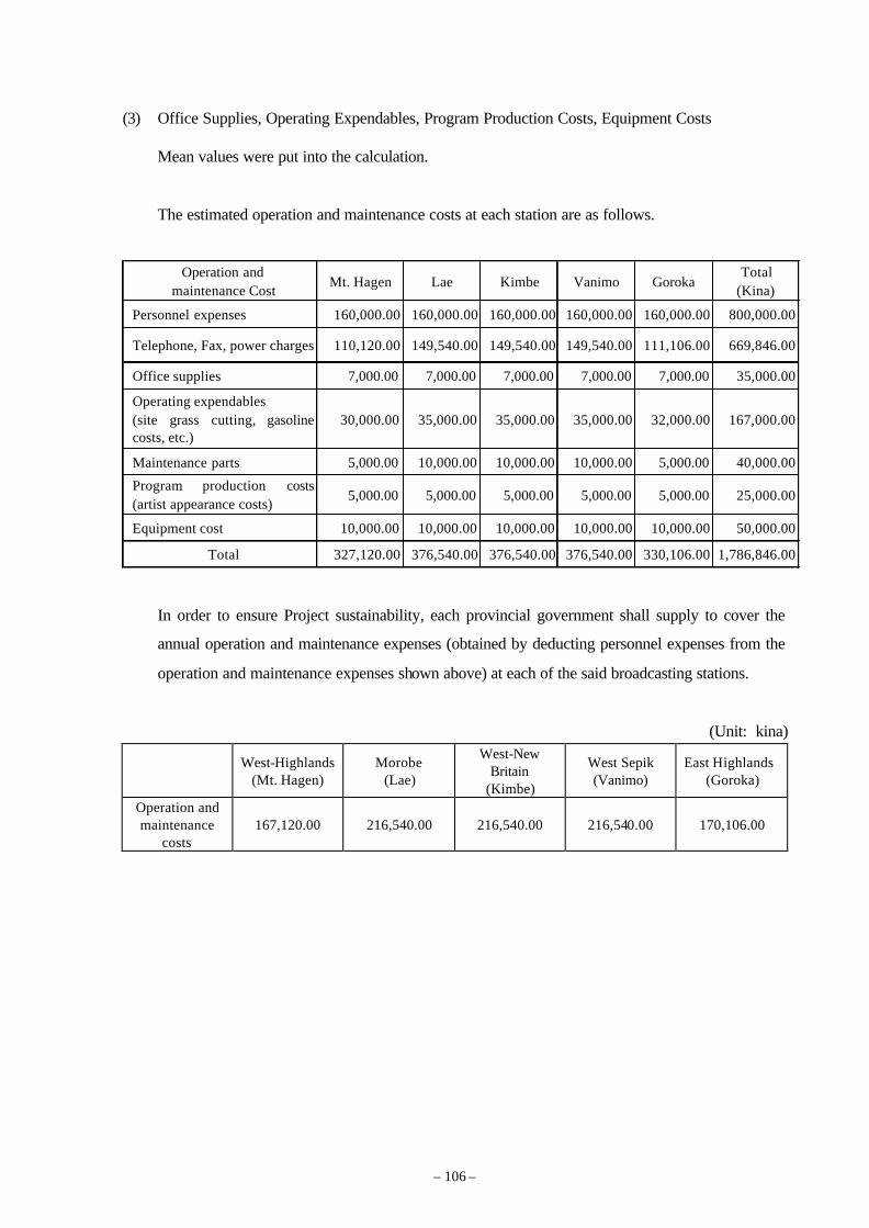
– 106 –
(3) Office Supplies, Operating Expendables, Program Production Costs, Equipment Costs
Mean values were put into the calculation.
The estimated operation and maintenance costs at each station are as follows.
Operation andmaintenance Cost
Mt. Hagen Lae Kimbe Vanimo GorokaTotal
(Kina)
Personnel expenses 160,000.00 160,000.00 160,000.00 160,000.00 160,000.00 800,000.00
Telephone, Fax, power charges 110,120.00 149,540.00 149,540.00 149,540.00 111,106.00 669,846.00
Office supplies 7,000.00 7,000.00 7,000.00 7,000.00 7,000.00 35,000.00
Operating expendables(site grass cutting, gasolinecosts, etc.)
30,000.00 35,000.00 35,000.00 35,000.00 32,000.00 167,000.00
Maintenance parts 5,000.00 10,000.00 10,000.00 10,000.00 5,000.00 40,000.00
Program production costs(artist appearance costs)
5,000.00 5,000.00 5,000.00 5,000.00 5,000.00 25,000.00
Equipment cost 10,000.00 10,000.00 10,000.00 10,000.00 10,000.00 50,000.00
Total 327,120.00 376,540.00 376,540.00 376,540.00 330,106.00 1,786,846.00
In order to ensure Project sustainability, each provincial government shall supply to cover the
annual operation and maintenance expenses (obtained by deducting personnel expenses from the
operation and maintenance expenses shown above) at each of the said broadcasting stations.
(Unit: kina)
West-Highlands
(Mt. Hagen) Morobe
(Lae)
West-New Britain
(Kimbe)
West Sepik (Vanimo)
East Highlands (Goroka)
Operation and maintenance
costs 167,120.00 216,540.00 216,540.00 216,540.00 170,106.00