Embed Size (px)
Citation preview

Chapter 2 Catalysis — Method Overview
Outline
This chapter introduces the Catalysis method for software development of object and component-based systems, building on the modeling notations of the Unified Modeling Language (UML).
Software development methods differ in three broad aspects: constructs, scope, and principles. The constructs provide the building blocks with which to describe problems and their solutions; scope defines which portions of the software devel-opment lifecycle are addressed; and the principles are the tenets underlying the intended usage of the method itself. These three aspects of any method are then integrated into an overall development process.
Catalysis has a small, con-sistent core of constructs, scopes, and principles.
Catalysis is based on a three primary modeling constructs that can be combined and applied recursively following three consistent principles, to support descrip-tions at any three essential levels or scopes from business or domain models through to detailed design and implementation. Section 2.2, Section 2.1 and Sec-tion 2.3 introduce these modeling constructs, levels or scopes, and principles.
It directly supports the needs of CBD.
The Catalysis approach is particularly well suited to building components with objects. Section 2.4 introduces some requirements for the modeling and design of component interfaces. Section 2.5 walks through an example of applying Cataly-sis to component-based interface specification and design. Section 2.6 shows Catalysis support for the architectural elements in CBD — the collaboration.
It applies from business to code.
Catalysis applies its core set of constructs from the business level to code. Section 2.7 illustrates Catalysis at the level of a business model. Section 2.8 discusses the powerful facility called frameworks that Catalysis uses to create generic and re-usable descriptions of patterns at all levels. Section 2.9 outlines a development process based on the method. Finally and Section 2.10 summarizes how the method fits into the landscape of today’s methods.
© Desmond D’Souza & Alan Cameron Wills 1998/May/11 09:53 2-47 of 90

2.1 Three Constructs, plus Frameworks
There are 3 principal con-structs, whose recurring patterns are described by ‘frameworks’
Catalysis is based upon just three primary modeling concepts: type, collaboration, and refinement. Upon this basis we build a great variety of patterns of models and designs, from individual classes and types, through design patterns and architectural descriptions, to business and problem-domain models. Types and refinement will be familiar to those accustomed to precision in abstract modeling techniques; collabora-tions and frameworks are perhaps more novel, and add an important degree of expressive power.
2.1.1 Collaboration — interactions among a group of objects
Collaborations define joint behaviors.
The most interesting aspects of design and architecture involve partial descriptions of groups of objects and their interactions with to each other. A collaboration describes how a group of objects interact. For example, a trading system may involve a buyer, seller, and broker. Their collaborative behavior may be described in terms of the detailed interaction protocols between them, or more abstractly in terms of a single high-level action, trade.
A collaboration defines a set of actions between typed objects playing certain roles with respect to other objects in that col-laboration. It can abstract details of multi-party interactions and of detailed dialogs between participants. It provides a unit of scoping, i.e. constraints and rules that apply within vs. outside the group of collaborators; and of refinement i.e. more detailed realizations of joint behavior.
Figure 8: Three modeling constructs, with patterns as frameworks
Purpose
specifies external behavior of an object
specifies behavior of a group of objects
relate different levels of description of behaviormap or trace from realization to abstraction
recurring patterns of collaborations, types, designs, etc.define generically, “plug-in” to specialize
Collaboration
Type
Refinement
ModelConstruct
Fram
ework
Type1
Type2
action Type3
action
2-48 Three Constructs, plus Frameworks

Chapter 5, Interaction Models — Use Cases, Actions, and Collaborations (p.205) describes modeling of interactions among a group of objects.
2.1.2 Type — external behavior of one object
A type describes the behavior of an object, but not its implementation.
A type defines what an individual object does by specifying its externally visible behavior. Whereas a class describes one implementation of an object, a type does not prescribe implementation; rather, it specifies the external behavior that any correct implementation must exhibit. Hence, a type is not the same as a class.
For example, a simple Calendar object for tracking appointments and events can be implemented in many ways, with different internal representations of the dates and events on that calendar. These different implementations could all exhibit the same externally visible behavior — captured in a specification of the Calendar type.
Precise description of behavior needs an abstract model of the state of any correct implementation, and of any information exchanged via input or output parameters. Catalysis uses a type model to provide this abstraction. Types characterize visible behavior of any object, component, or system in terms of con-ceptual attributes, and operations that affect these attributes. For a simple type, these attributes and their types may be listed
textually; more complex types may have a type model drawn graphically, and even factored into multiple separate descriptions.
Chapter 3, Static models — Object Attributes and Invariants (p.93) will describe how attributes are used to abstract variations in the implementation of object state, and Chapter 4, Behavior Models — Object Types and Operations (p.129) describes how opera-tion specifications can describe externally visible behavior of an object, independent of different algorithmic implementations.
2.1.3 Refinement — layers of abstraction
Refinement is a relation-ship between abstraction and realization.
A refinement is a relationship between two descriptions of the same thing (types, col-laborations, type and class, etc.) where one — the realization — conforms to the guaran-tees of the other — the abstraction. The two descriptions are at different levels of detail, but all guarantees made by the more abstract description are retained, perhaps in a different form, in the more concrete version. A refinement is usually accompanied by a mapping that justifies this claim by showing how the abstraction is, in fact, met by the realization; together with reasons for specific design choices made. Software design is the process of creating a refinement of some desired or specified behavior.
Refinement takes many forms.
There are several kinds of refinement. A component design — a realization — conforms to the component specification — its abstraction. A class that implements its behaviors in terms of a particular representation conforms to a type that specifies behavior in terms of an abstract model of state. Similarly, a par-ticular sequence of fine-grained actions may realize a single more abstract action. Refinement in Catalysis is far more gen-
eral than the standard ideas of sub-classing and sub-typing.
Type
type-model attributes
operations
abstraction
realization
mapping
Three Constructs, plus Frameworks 2-49

For example, an abstract model of a person may use an attribute money; more detailed models, or implementations, may be based on personal bank accounts, credit cards, and cash. The appropriate mappings would show how the different realizations map to the simple abstract attribute money, and how the behavior descriptions at the abstract level still hold for each realizations. Similarly, an abstract action getCash, may be refined to many possible sequences of interactions, such as an ATM-based insert-Card, enterPIN, withdrawCash.
Refinement is the formal basis for traceability
A significant part of a Catalysis development process consists of refining or abstracting a description — creating a series of re-factorings, extensions and transformations that ultimately shows the implementing code to conform to the highest-level requirements abstraction (though not necessarily produced in top-down order!). Re-engineering, on either the large scale of a business process, or a simpler re-factoring of a design, con-sists of first abstracting the existing design to a more general requirement, and then refining it to a new design, e.g. with new features or better performance.
Refinement is a focus in design reviews
In Catalysis, a “design review” is largely concerned with refinement; what did you set out to build, and how did you build it? It addresses the reasons for the design choices you made, and examines the mappings from your design realization to the abstrac-tion, to check that the design fulfils all requirements stated in the abstraction.
Catalysis uses packages to separate different levels of abstrac-tion, permitting re-use of abstract models by multiple inde-pendent realizations. A package groups together a set of definitions — including types, actions, collaborations — that can then be imported into other packages, making its defini-tions visible in the importing package.
Chapter 7, Abstraction, Refinement, and Testing (p.265) will discuss refinement in detail; basic forms of refinement will be introduced in Section II, Modeling with Objects (p.91).
2.1.4 Frameworks — generic re-usable models and designs
All three constructs show recurring patterns
Specifications, models, and designs, all built with the three preceding constructs, all show recurring patterns of structure and behavior. For example, the type model for a component that schedules instructors for seminars, and one that sched-ules machine time for production lots, both look remarkably similar at an abstract level — a generic type-model. The col-laborations for processing an order for a book at an on-line book store, and for accept-ing a request to schedule a seminar, are also similar in structure — a generic collaboration. The design transformations involved in designing an editor where you select a shape before editing it are similar to those in designing seminar requests, where you select the seminar topic before making your request — a generic refine-ment.
Frameworks define pat-terns that can be applied in many different con-texts.
The key to such patterns are the relationships between elements, as opposed to indi-vidual types or classes. An application of such a pattern specializes all the elements in parallel and mutually compatible ways, as opposed to an individual specialization of each element. Catalysis provides a fourth construct to capture the essence of such pat-
package-1
package-3package-2
pattern
2-50 Three Constructs, plus Frameworks

terns: frameworks. A framework is described as a generic package. A framework is applied by importing its package, and substituting problem-specific elements for the generic model elements as appropriate.
A framework defines patterns in generic terms by using placeholders for elements. It can be applied to a family of related types to generate different models and designs. A framework may be a model for a single object or a collaboration; or a static relation-ship between objects; or a single type; or a class; or a package of related classes; or a particular way of transforming a specification to a design.
Chapter 10, Model Frameworks and Template Packages (p.389) describes how frameworks are defined in Catalysis, and shows how frameworks provide an enormous degree of extensibility to modeling constructs by abstracting and summarizing recurring pat-terns, even providing the ability to define entirely new kinds of model elements.
Three Constructs, plus Frameworks 2-51

2.2 Three Levels of Modeling
Catalysis addresses three levels of modeling: the problem domain or business, the component or system specification (externally visible behavior), and the internal design of the component or system (internal structure and behavior).
2.2.1 Problem Domain or Business: the “Outside”
The problem domain level describes concepts without concern for soft-ware boundaries.
“Domain” or “business” covers whatever concepts are of primary relevance to your clients and their problems (not necessarily business in the sense of something that makes money) i.e. the outside environment in which any target software systems will be deployed. If you are designing a multiplexor in a telecommunication system, your users are the designers of the other switching components, and the business model will be about things like packets, addresses, etc. If you are redesigning the ordering process of a company, the business model is about orders, suppliers, people’s roles, etc. If you are being asked to design a graphical editor, your business is about docu-ments and the shapes thereon.
As-is and to-be domain models lead to compo-nent specifications.
It is sometimes useful to distinguish an as-is model of the domain — which describes how things currently work, from a to-be model — which is a re-design of the as-is model. The to-be model will introduce new software components, or changes to exist-ing ones, that will need to be individually specified in the next level of component spec-ification.
There may be many views of a business. The concerns of the marketing director and the personnel manager may overlap. Even where they share some concepts, one may have a more complex view of them than the other. The modeling constructs support separating and joining of such views.
Figure 9: Three recursive levels of description
Domain/BusinessDomain/Business
Component SpecComponent Spec
Internal DesignInternal Design
Goal
Specify Solution: “Boundary”scope and define component responsibilitiesdefine component/system interfacespecify desired component operations
Identify Problem: “Outside”establish problem domain terminologyunderstand business process, roles, collaborationsbuild as-is and to-be models
Implement the Spec: “Inside”define internal architecturedefine internal components and collaborationsdesign the insides of the system/component
Level/Scope
2-52 Three Levels of Modeling

Chapter 15, How to build a Business Model (p.549) describes how to go about building a business model.
2.2.2 Component Specification: the “Boundary”
A component specifica-tion describes external behavior of a component.
A component (or system) specification describes the external behavior required of the component or system in the context of the domain or business model that describes its environment. Catalysis uses a type specification to describe behavior visible at the boundary between the component and its environment. The type specification itself may appear in the form of a type-model, operation specifications, and state-charts.
A component is specified as a type.
A type specification defines the actions, often identified in the problem domain model, that a component or object participates in. These actions are defined in terms of its effect on some attributes that characterize the state of that component, and any information exchanged with that component. Some attributes are more complex than others, and may be drawn graphically in a type-model.
A type model may be of sufficiently complex that it’s elements have “interesting” state transitions. In such a case, one might build one or more statecharts to describe the states and transitions between states caused by the actions. State-charts provides an alternative, fully integrated, view of action specifications.
Chapter 11, Components and Connectors (p.437) discusses more general component models, in which the kinds of the “connectors” between components can themselves be extended to include new forms of component interaction, such as properties and events. Chapter 16, How to Specify a Component (p.581) describes how to go about writ-ing a component specification.
2.2.3 Component Internal Design: the “Insides”
A component is inter-nally designed as a col-laboration of other components.
The internal design of a component (or entire system) describes how the component is assembled from smaller parts that interact to provide the required overall behavior. Each component is itself designed as an interacting group of finer-grained compo-nents, until one reaches parts that already exist, implemented in a library or provided by a programming language or implementation generator. The design is described as a collaboration, and must conform to the specification of that component. Note that the context for the internal design is provided by the type-model in the component specification.
At some point during internal design, one may also take into consideration the tech-nology being used to implement the component or system, and make trade-offs on performance, maintainability, reliability, etc. Hardware (solitary or distributed) and software (database, user interface, programming language, tiered architectures) choices affect how the system is implemented.
Chapter 17, How to Implement a Component (p.629) describes how to do the internal design of a component. Chapter 18, How to Reverse-Engineer Types (p.671) shows how, given an existing design and implementation, to reverse-engineer a more abstract external model and specification of its behavior.
Three Levels of Modeling 2-53

2.3 Three Principles
Catalysis is founded on three core principles — abstraction, precision, and pluggable parts — which underlie the application of the method and its constructs.
2.3.1 Abstraction
To abstract means to describe just those issues or decisions that are important for a pur-pose, while deferring details that are not relevant.
The word “abstract” often has connotations like “theoretical” and “esoteric”, “academic”, and even “impractical”. In our context, however, it means sep-arating the most important
aspects of a problem from the details, enabling us to tackle first things first. As such, it is essential to dealing with complexity.
Important decisions should be made early.
Think of a software development project as a stream of decisions. Some of them depend on others. There would be no point in trying to design the database tables before establishing what the system is going to do. In other words, some decisions are more important than others: making them is a prerequisite to getting the others right.
Some of the important abstractions include:
• Business model and rules — what context our design is operating in.
• Requirements — what must be done, as opposed to how it is to be achieved.
Figure 10: Three principles in Catalysis
Intent
expose gaps and inconsistencies earlymake abstract models accurate , not fuzzy
focus on essential aspects , deferring othersuncluttered description of requirements and
architecture
all work done by adapting and composing partsmodels, architectures, and designs are assets
Abstraction
Precision
Pluggable Parts
Principle
Abstract
• Deal with far-reaching requirements and architecture decisions uncluttered by detail
• Layered models — from business rules and processes to code
• Methodical refinement and composition of components
2-54 Three Principles

• Overall schemes of interaction, rather than detailed protocols.
• Architecture — the big decisions about major components and how they will interact. (Not necessarily the exact identities of the major components, but at least what roles they will play, what they will be required to do. Requirements again!)
• Concurrency — what functions can be performed simultaneously, and how they will avoid interference while working in co-ordination.
How many projects have we seen where some of the important choices don’t get made — don’t even get noticed — until way down the line, often in coding? (And almost as many where people are worrying about trivial problems, to avoid tackling the big issues!)
We need a way to clearly describe abstractions
We need a language for talking about the important decisions, separately from all the clutter of performance and platform that full implementations involve. Normal pro-gramming languages are not useful for this task: they are intended for expressing solutions rather than problems. For this reason, requirements and other high-level descriptions are usually written in a mixture of prose and ad hoc diagrams. However, informal prose and ad hoc diagrams are rarely accurate (or even correct) representa-tions of the systems that we intend to build.
2.3.2 Precision
Whereas code is precise, natu-ral language and ad hoc dia-grams are not. How often do groups of analysts or design-ers discuss requirements around a whiteboard and leave with different interpreta-tions of the problem to be solved? We too often produce
reams of documents ridden with latent bugs, ambiguities, incompleteness, inconsis-tency, and overspecification. Documentation that is concise and accurate is far more likely to be useful.
Code is precise, but not abstract enough for some purposes.
During implementation, the unforgiving precision of the programming language forces any gaps and inconsistencies to the surface. It is for this reason that many of us feel confident about a design only when the code has been written. Unfortunately, code also makes us deal with a great many detailed programming language and plat-form-specific issues.
And abstract does not imply inaccurate.
Abstract descriptions are not necessarily ambiguous. If I say “I am quite old, really”, that’s ambiguous! You might think I am geriatric, or perhaps I am a teenager pleased at nearing the age of eighteen. But if I say “I’m over the age of 21”, that is abstract, but perfectly precise. There is no question about what I am prepared to tell you, nor about what I am not prepared to give away.
Precision enhances test-ability
Abstract high-level descriptions that are not clearly defined are often impossible to either refute or defend convincingly. The same holds for code-level description of interfaces. At the requirements level, precise descriptions help provide a vocabulary
Precise
• Expose gaps and inconsistencies early by being precise enough to be refutable
• Trace requirements explicitly through models
• Tool support at semantic level well beyond diagrams & databases
Three Principles 2-55

that all involved parties can agree on. When architectural decisions are captured with some precision, we can review detailed designs for conformance to those decisions. At the level of code interfaces, precision directly feeds into the generation of tests. Although being precise takes some effort, when appropriately used, it enhances test-ability and confidence at all levels.
Precise abstractions are the ideal combination.
Given a precise notation for abstractions, it becomes possible to decide whether or not a given design conforms to the abstraction. It also becomes possible to trace exactly how each piece of an implementation realizes each requirement, and to build tools that help keep track of the propagation of changes in either requirements or imple-mentations.
2.3.3 Pluggable Parts
Building good soft-ware is about designing and plugging together components. Each component is a piece of design or implementation effort that is cohe-
sive as a unit. It can be built, moved around, stored in a library, or incorporated in a variety of designs.
Software built without well defined components will be inflexible — difficult to change in response to changes in the world in which it works. If you don’t use previ-ously built components in your designs, then you’re doomed to continually cover the same old ground every time you write a new application; and to make a lot of the same mistakes. And changes will be a lot more difficult to incorporate. This holds at all levels, from code to requirements.
Good components can be adapted and re-used
Components use other components. A good component is one that can be made to work with a wide variety of other components, the key idea behind polymorphism. Such a design only makes sense if you can express accurately what you expect of the other components to which it may be coupled. Plug-compatibility relies on unambig-uously specified interfaces.
Component assembly spans requirements to code
This idea of adapting and using components to produce other components should apply at all levels of development, from business models, through components that encapsulate models and generic problem specifications, to assembling binary compo-nents to produce a running system. Every step of a Catalysis development process, from business models to code, adapts and assembles other pieces of models, specifica-tions, designs, and code.
Pluggable Parts
• Get the most from each piece of design work
• Fast, more reliable development by re-use
• Re-use not just classes — also frameworks, patterns, and specifications
2-56 Three Principles

2.4 Interfaces of Objects and Components
Component-based development is the art and science of assembling components so that they interact with each other as intended, to provide some higher-level of func-tionality. The goal is to build systems by plugging together the right combination of components in the right configuration. Each component offers, and requires, specific services via its interfaces.
2.4.1 Objects present multiple interfaces — real world and code
Real world objects play multiple roles
Objects in the physical world participate in many interactions, playing different roles in each one. A person who stays at a hotel plays the role of a hotel guest in his interac-tion with the front desk and room service. The same person when traveling to and from the hotel plays the role of a passenger in his interaction with the airline and its passenger related services.
Each role requires a dif-ferent interface
Each such role played requires specific behaviors from this person i.e. the interface or apparent type of this person varies across the different roles played. The relevant actions of a person as a guest would include making a hotel reservation, checking into and out of the hotel, using hotel services while checked in. Thus, the apparent type of this person in the context of its hotel interactions is different from its type in the con-text of its travels. This would be reflected in code for a model of this “real” world.
Figure 11: Multiple roles for real world objects
Passenger check Baggage board deplane
Guest check In room Service check Out
What Type? What Type?
AirlineHotel
Figure 12: An object in code also has multiple types — Java example
interface Guest {checkIn ();roomService();checkOut ();
}
interface Passenger {checkBaggage ();board ();deplane ();
}
interface Guest {checkIn ();roomService();checkOut ();
}
interface Passenger {checkBaggage ();board ();deplane ();
}class Both implements Guest, Passenger {
// implementation …. }
class Both implements Guest, Passenger {
// implementation …. }
object:Both
Guest
Passenger
HotelAirline
Interfaces of Objects and Components 2-57

An object in code also plays multiple roles
Interesting objects in code can also play multiple roles. Suppose we implement a class Customer which represents a customer in our software. Any instance of this class will play different roles with respect to other software components, either due to different roles from the business domain itself (as illustrated above), or due to different techni-cal services required in the software itself. For example, it may provide one set of operations for its appearance on a user interface — via its Displayable interface; and another set of operations for being saved and restored from some persistent storage medium — via its Persistent interface.
interface Displayable {// a Displayable object must support two operationsdisplay (Surface on); // display onto a Surfacemove (Delta by); // move by a Delta
}
interface Persistent {// a Persistent object must support two operationssave (Storage to); // save its contents onto a Storagerestore (Storage from); // restore its contents from a Storage
}
It’s implementation sup-ports multiple interfaces
class Customer implements Displayable, Persistent {// a customer is both a Displayable and a Persistent object
....}
2.4.2 Components demand precise interfaces
Components are described by their inter-faces
When we assemble components we do so based on the interfaces they support, with-out knowledge about their internal design and implementation. Except for the most trivial components, simply plugging parts together without well specified interfaces is unlikely to yield the desired result1. And, even though some users of well designed components, for example user-interface widgets, can use them without knowing the precise details of their interfaces, the designers of kits of such components must define clear interfaces; so must those who specify standard components and architec-tures for standardized services, publish those specs, and certify implementations.
1. A style sometimes called plug-and-pray!
2-58 Interfaces of Objects and Components
Interfaces may be checked at compile and run-time.
A central part of an interface definition will be the list of messages the component understands. When components are coupled together, compilers and run-time sys-tems can check that each provides at least the services expected by the other.
But signatures are hardly enough.
But a list of signatures is not enough. While names can be suggestive, they can easily be ambiguous, and are not enough to document what one component expects of the other. So interfaces should be accompanied by other documentation — traditionally written in a natural language.
Consider this progres-sion of interfaces.
Consider these three black boxes in turn. Each of these could be a complete system, or a component used within a larger system. For example, the Editor could be one part of an email application that dealt with structured text and graphics.
We need meaningful names.
Could you use the Thingami box? Probably not, because you don’t have a clue about what it or its operations mean; it has no suggestive names.
But suggestive names, on their own, are quite ambiguous.
How about the Editor box? You might say “Sure!”, since you can guess at the mean-ings of the different terms. However, your guess might be different from mine, or from someone who claims to implement such a box. Without additional specification we would not know if adding an element replaces another or simply moves it; in either case, are the elements automatically laid out after the edit? Clearly, suggestive names and signatures are not enough to describe what a component provides.
Figure 13: Widely used components must have precise interface specifications
?certify and publish
“Type” specwhat is expected ofany “plug-in”
will work with...
is one implementation of...
Figure 14: Signatures are not enough to specify an interface
Thingami
frob (Thing, int)Thing fritz(int)
NuclearReactorCore
add (ControlRod, int)ControlRod remove(int)
Editor
spellCheck()layout()addElement(…)delElement(…)
Interfaces of Objects and Components 2-59

Unstructured informal specs leave many prob-lems latent until coding.
Natural language is ambiguous. How often have you found that a requirement has been understood differently by writer and readers? Natural language often leads to this. Moreover, attempts to write precise natural language specifications frequently results in verbose, equally error-prone descriptions. How often have you found that it is only when you get to coding that you notice essential decisions are missing from the specification? It is the precision of program code that exposes the gaps and incon-sistencies. We need a precise way of writing interface specifications without losing the more readable narrative.
No one will use a reactor based on signatures alone!
The NuclearReactorCore box underscores this point. Although we all know what the operations should do, the implications of a wrong guess or a misunderstanding would surely (hopefully!) stop us from using such a box without a much more thor-ough description of the assumptions, guarantees, safety conditions, etc. for using its operations.
Widely reused compo-nents need precise inter-faces.
If we are to move towards reuse of non-trivial components, and hope for meaningful tool support for designing with components, we will need more precise descriptions of their behaviors. For components we expect to be widely used, it is worth spending more effort on precise interface definitions. Even in the world of COM components we are starting to see the results of poor characterization of interfaces. Users often purchase some OCX based upon some marketing literature, insert it into their applica-tion, and attempt to use it — only to realize that their “guesses” about precisely how it behaves were wrong. When you purchase the executable code for any component, it should be accompanied by the specification of each of the interfaces it implements.
Interface specs must be both abstract and precise
Our specification must be independent of implementations, since the whole point of component-ware is to permit many different implementations — i.e. they must be abstract. At the same time, the specifications must adequately cover all expected aspects of behavior expected of any implementation — i.e. they must be precise.
2-60 Interfaces of Objects and Components

2.5 Component-ware — an example
In this section we will show how a Catalysis type-model lets us capture abstract inter-face specifications in a precise way without compromising alternative implementa-tions, how a component can be internally designed to conform to such a specification, and how the decisions can be effectively separated and layered.
2.5.1 Types — Specifying Component Interfaces
Start with an informal specification of each operation
In order to precisely describe an interface of an object — i.e. its type — we start with a list of its operations. Thus, an object of type Editor must support the operations listed1. For each operation we document, informally at first, the effect of invoking that operation and the conditions under which those effect are guaranteed.
Type-model provides vocabulary for describ-ing operations
The specification of each operation invariably uncovers a set of terms — the vocabu-lary needed to describe those operations. These terms — word, contents, dictionary, etc. — must be defined as well. We formalize this vocabulary as the type model of the edi-tor. It states that the state of the editor can be abstractly modeled as an attribute con-tents that is a set of elements, and an attribute dictionary that is a set of words. Words are themselves elements in the editor’s contents, which also contains some composite elements that are themselves comprised of other elements (e.g. paragraphs, tables)
Model ≠ implementationThe type model does not prescribe an implementation for Editor; it simply defines a vocabulary for specifying behavior. Any correct implementation of this specification will have some representation for the terms contents, element, word, dictionary, etc. The concrete form in which they are implemented may differ, but the implementation will have some (possibly indirect) mapping to the terms of the specification. Hence, the type model will be a valid abstract model of any correct implementation.
1. This example does not explicitly represent documents, for simplicity.
Figure 15: Type model and (informal) operation specifications
spellCheck()layout()addElement(…)delELement(…)
Editor «type»
*
ElementpreferredSizeposition
Word Composite
*
*
dictionary
contents
type-model = vocabulary
every element is positionedso that its preferred size canbe accommodated
every word in contents iscorrect by the dictionary
Editor Type Specification
operations specified in termsof the type model
type specificationusually in separatepackage
Component-ware — an example 2-61

Operation specs and model can be formalized
The specifications of the operations can now be made as formal as required1, based on the terms provided by the type model. Here is a simplistic specification of spell check.
Editor:: spellCheck ()post // every word in contents
contents #forAll (w: Word |// has a matching entry in the dictionarydictionary #exist (dw: Word | dw.matches(w))
)
2.5.2 Collaborations — Designing from Components
We implement a type using smaller compo-nents
The Editor type is itself implemented as an assembly of smaller components. To design something that conforms to a type specification, we bring together components that collaborate in such a way as to behave jointly as required by the type specifica-tion. One possible design decomposes the editor into a spelling checker, layout man-ager, and editor core.
Component partitioning depends on many fac-tors.
Many factors influence such internal component partitioning:
• Separable functionality: layout is separable from spelling checking and from actual editing of the document structure. Spelling checking verifies (or modifies) the spelling of words in the document. Layout computes optimized positions and sizes for structured elements in the document, including line and page breaks, floating graphics and tables, etc.
• Available components: spelling checking is such a commonly required service that an entire market of 3rd party spelling checkers exists. Provided that these dif-ferent implementations all conform to some minimal specification, we can design our editor to use a bought component.
• Encapsulating variability: there may be many different algorithms for computing the layout of a document, with different trade-offs in aesthetic quality and com-putation times.
1. We use the Object Constraint Language (OCL) defined as a standard in the UML.
Figure 16: Designing from Components
E-Corenext word
replace word
maximum sizeresize
children
Spell Checker
spellCheck()
Layout Manager
layout()dictionary
words
Editor
spellCheck()layout()addElement(…)delELement(…)
Editor Internal Design
internal design in a separate package from the specification
2-62 Component-ware — an example

• Parallel development: by separating out components and designing their inter-faces early, we enable parallel development by different teams of people.
• Potential for reuse: even if there are no spelling checkers available, we could design a spelling checker component that was not specific to our editor, and re-use it in many other contexts.
We must design the internal interactions between these components to provide the overall functionality required of the editor. In the process, we must once again specify the interfaces each component offers to the others. We have described these in Figure 17 directly at the level of operations nextWord and replaceWord on each com-ponent; however, Catalysis would have permitted us to defer this design decision, and instead describe an abstract action checkWord involving both the spell checker and the editor core.
Internal components also offer multiple interfaces.
In this design, the component called EditorCore has separate collaborations with the spelling checker and the layout manager, through two very different interfaces it implements. Each interface will, in turn, be specified as a type, just like the editor itself. As shown in Figure 16, the terms from the original type model — dictionary, word, etc. — appear in different forms in each of the design components.
In this case, the editor core must support an interface to the spelling checker through which the spelling checker requests one word at a time, and optionally replaces the last word checked, i.e., the editor appears like a straightforward sequence of words. In contrast, its interface to the layout manager needs a model of the nested structure of all elements in the document with their sizes and positions, rather than a sequence of words.
2.5.3 Component Pluggability
The reason for writing precise specifications of a component interface is to ensure pluggability of components, with obvious advantages.
Figure 17: Interaction Design: Sequence Diagram for spellCheck
: SpellChecker : EditorCore
spellChecknextWord
replaceWord
nextWord
Component-ware — an example 2-63

Component interfaces enable pluggability and re-use
Our EditorCore will work with any spelling checker, now that we have defined the type of the Editor to SpellChecker interface. Similarly, the spelling checker can work with anything that provides the interface that the editor core must implement — the SpellCheckable interface — through which it appears like a simple sequence of words. We can thus use any spelling checker with the editor core, and can use a spell-ing checker with any component — such as a database record, or spreadsheet, or a range in a spreadsheet — that implements1 the SpellCheckable interface.
2.5.4 Refinement — Abstract Action and Detailed Dialog
Detailed actions uncover new interaction paths
In the process of designing this component, we realize that spell-checking does not necessarily apply to a complete document. The user may abort a spell-check before it completes, or may only spell check a particular selection. This was not foreseen in the original component specification. Moreover, the original specification was not at the level of individual user-interface actions, such as abort.
Figure 18: Each component implements multiple types and interfaces
Figure 19: Any implementation can by plugged-in
E-CoreSC LM
Layout Managermaximum Sizeresizechildren
Layoutable
Elemsize
descendants *Spell-Checker next word
replace word
SpellCheckable
Wordseq *
curr
Spell Checkable
next Wordreplace Word
Wordseq *
DB RecordE-CoreAcme Spell Bee
SpellChecker
1. An interesting re-phrasing would be “that can masquerade as...”.
2-64 Component-ware — an example

An abstract action can cover multiple paths
We do not want treat these as separate actions at the abstract level, or even as an exception to an action. Instead, to simplify the specification, we introduce an action that spell checks some region — which could be the entire document, or a selection, or some portion of either one until an abort; we can then use this specification for any partial or complete spell check. Of course, our type model will be extended to include a precise definition of the concept of a region that contains certain words.
Editor::spellCheck (r: Region)post // every word in that region
r.words #forAll (w: Word | // has a matching entry in the dictionarydictionary #exist (dw: Word | dw.matches(w))
)
There is a mapping from detailed sequences to abstract action
At the more detailed level, the user may initiate a spell check (optionally on a selected region), accept some number of proposed corrections, and may abort that spell check before completion. Any valid sequence of detailed user actions — including start spell check, accept corrections, and abort — has a mapping to the abstract spellCheck spec-ification, with the region, r, being defined by the detailed sequence. The mapping can be formalized, and will be an important part of a design review.
Terms in the original specification are defined in the design
The original specification of the type Editor introduced terms such as dictionary, con-tents, word, position, etc. In our design these terms may be refactored and renamed across the design components. However, no matter what internal design we choose, there must be a mapping from the design to the specification; it would be impossible to implement the Editor without anything corresponding to a dictionary.
2.5.5 Refinement — Type and Class
Distinguish specs from implementations
There is a essential separation between a type specification with its associated type model, and a particular implementation of that specification. Since the UML notation for a type model resembles a traditional class model, it is a common mistake to inter-pret it as a set of implementation choices in terms of classes, data members, pointers between classes, etc.
The spec is an abstraction of every correct imple-mentation
However, the type model is an abstraction of any such implementation class, such as the one below. This is a Java class that implements both the SpellCheckable and Lay-outable types. The implementor has made the appropriate trade-offs and chosen a stored representation that can sup-port both interfaces — a hierarchical tree of all elements. Since the spell-checking functions only care about words, we have implemented a special iterator1 spellPosition that traverses the tree and only returns elements that are words. The nextWord and replaceWord operations use this special iterator.
class EditorCoreClass implements SpellCheckable, Layoutable {// store a tree of all elements — graphics, words, characters, tables, etc.private ElementTree contents;
1. An iterator is a small object that acts as an index into some collection. It provides access to the element at the current index position, and can be moved forward in the collection.
contents
para-1 table
word1
word2
fig1
row1row2
word3fig2
Component-ware — an example 2-65

// this iterator traverses all elements in the contents tree in depth-first orderprivate DepthFirstIterator elementIterator = contents.root();// this iterator only visits Word elements, ignoring othersprivate WordIterator spellPosition = new WordFilter (elementIterator);// return the “next” word in the treepublic Word nextWord () {
Word w = spellPosition.word();spellPosition.next();return w;
}// replace the last visited word with the replacementpublic void replaceWord (Word replacement) {
spellPostion.replaceBefore (replacement);}
}
An implementation must conform to a specification
This implementation does not store a sequence of words, although the type model in Figure 18 on page 64 is described in terms of such a sequence. Does that make this implementation incorrect? Clearly not. Any correct implementation must conform to the specification. This means that any guarantees made by the specification should hold true for the implementation. In this case, the vocabulary used in the specification is not directly represented in the implementation, so one needs a mapping between the implementation and the specification. Informally, the “sequence of words” is the depth first ordering of the contents tree, with all non-word elements discarded. This mapping could be expressed precisely in OCL:
wordSeq = contents.asDepthFirstSequence #select (e | e.isKindOf (Word))
An internal design review of the editor’s design would inspect this mapping, and question it against the required behaviors of nextWord and replaceWord.
2.5.6 The Advantage of Refinement
Refinement is a funda-mental concept
We have briefly illustrated two of the refinements supported by Catalysis. Refinement is a fundamental part of our approach. It allows us to create precise yet abstract descriptions of some interface or interaction, and convincingly refute or defend that description even at much more detailed levels of design.
What code changes necessitate updated models?
The idea of refinement also addresses a very real problem in object-oriented and com-ponent-based software development, where problem domain models, component specification models, design models, and implementation are all based on similar con-structs:
I have just made a change to my implementation. Must I update my external design docu-ments? Are my analysis models now invalid?
Many projects have no clear answer
We have seen some projects where the design and analysis models are interpreted as not much more than graphical drawings of the implementation. Other projects have a somewhat vague notion of the analysis models being more abstract than the code, but no precise separation between them. As a result, there are no clear rules about what changes must propagate up from the implementation to the more abstract descrip-tions. As a result, these models are eventually abandoned and “only the code tells the truth”.
2-66 Component-ware — an example

A code change may sim-ply need a different map-ping.
The simple answer is: if you can redefine your mappings so that things said in the analysis model are still true of the new implementation (via the new mappings), your analysis models are still valid. When the design is changed, the analysis or specifica-tion does not need to be updated if we can re-define the mappings appropriately. This simple measure de-couples documentation and models between analysis and design, and makes it easier to maintain correct and useful abstract descriptions of an evolving design and implementation.
The flexible mappings of a refinement are the focus of design reviews
This provides considerable flexibility with regard to design approaches. One could create an object-oriented design in which there is a simple mapping from types to classes, or one could group types together to form components and frame-works, including wrappers for legacy systems, or one could devise a transformational approach in which types are trans-formed to an implementation according to a set of architec-tural rules, or any other approach in which a refinement mapping can be defined. The relationship between the parts holds for top-down, bottom-up, or any combination of development process. Refine-ment also provides a sound basis for use-case driven development, in which abstract actions are refined to detailed external and internal interactions, as we will show in subsequent chapters. And lastly, refinement is a major focus during design reviews.
2.5.7 Recursive Process
The process continues recursively to some level of ‘primitives’
We recursively continue with the partitioning components, designing interfaces and interactions, and implementing the next level of components. One design of the SpellChecker could use a Dictionary component, with very basic operations like lookup, and learn. And this process continues until we reach the level of existing class or component libraries, or primitive types and constructs in the programming lan-guage itself.
specification
design-1
new
design-2
mapping
further abstraction
Figure 20: Component design continues recursively
Spell-Checker
Checker-Core
Dictionary
lookup()learn ()
Moby’sDictionary
Spell Checker Design
Component-ware — an example 2-67

2.6 Component Architecture
Component interfaces represent roles
Our design process focuses on the interfaces and interactions of objects. The familiar picture of an object as a jelly donut, with the data in the core and the services on the outside, becomes modi-fied as we start thinking of an object as offering many, possibly different, sets of services. In a component-centric design, it is quite feasible to have a component offer many different services for the different problem domain roles it plays and the different technical infrastruc-ture services required.
2.6.1 Collaborations as design units
Interface-based design leads to collaborations as a design unit
Such interface centric design leads us naturally into treating collaborations as design units. Each interface that a component provides only makes sense in the context of related services and interactions with other components; specifically, in the context of related interfaces of those other components. Hence it is logical to group these related interfaces together into a design unit that defines one architectural design of a certain service. We call this unit a collaboration.
A collaboration is a par-tial design of a group of objects
Collaborations are design units that can be individually defined, and composed to make bigger ones. Each collaboration defines how a group of objects can interact with each other to jointly provide a certain behavior. A collaboration can often be consid-ered as a design of a particular service; several such services are composed within any particular application. For example, we can decompose our editor design as shown in Figure 22.
Figure 21: Collaborations can be de-composed and re-composed
Composition of 1+2
Passenger Guest
Guest
Collaboration 2Collaboration 1
Passenger
2-68 Component Architecture

Spelling checking is a collaboration
If we took our design for spelling checking and abstracted from specifics of the editor, we get a collaboration for spelling checking. This collaboration could be documented in the implementation code as a pair of related interfaces in a Java package, and it could be used in contexts other than the editor as an architectural design unit for spelling checking. This design could also be associated with a default implementation of one or both interfaces.1
2.6.2 Composing collaborations
A particular design com-bines collaborations in a specific way
The design of our editor thus consists of two distinct collaborations; one for spelling checking, the other for layout. The EditorCore component could be implemented by a class (perhaps making use of other classes, either by composition or class inheritance) that implemented its interfaces in both collaborations.
// EditorCore implements 2 interfaces, one for its role in each “service” collaborationclass EditorCore implements SpellCheckable, Layoutable {
Figure 22: Collaborations in the Editor design
E-Corenext word
replace word
maximum sizeresize
children
Spell Checker
spellCheck()
Layout Manager
layout()
Figure 23: Spell Checking: a collaboration in code
1. We will show later how frameworks can be used to make this architectural element much more generic and re-usable.
package patterns.Spellings;
interface SpellChecker {void attach (SpellCheckable target);void spellCheck ();
}
interface SpellCheckable {Word nextWord ();void replaceWord (Word replacement);
}
Spellings
Component Architecture 2-69

// the operations for one rolepublic Word nextWord ();public void replaceWord (Word replacement);
// the operations for the other rolepublic Enumeration children();public void resize (Element toResize, Rectangle size);...
}
Of course, there is no intrinsic reason why this composition of collaboration should be
unique to the editor. We could use it as a pure design element without any implemen-tation by replacing the EditorCore class with a corresponding interface.
2.6.3 Application architecture from collaborations
Each collaboration is an architectural element
In a component-based implementation, the components themselves are not the most interesting part of the application architecture. Rather, each collaboration is an archi-tectural element, and the choice and composition of collaborations — the way the col-laborations overlay the component boundaries and interact with each other — defines the architecture of the application.
Each can be used in dif-ferent contexts
Our spelling checking and layout collaborations could be used in a variety of other component systems, such as a database application in which records can be spell-checked and automatically laid out, in addition to being persistent. The application architecture of these applications would share this common architectural element.
Figure 24: Composing collaborations
Spellings
SpellCheckableSpellChecker
Layout
LayoutManagerLayoutAble
Editor-Structure
E-Core
the two collaborations work together through the Editor
LayoutManagerSpellChecker
2-70 Component Architecture

Application, technical, and component architec-ture can be separated.
The “application architecture” is defined by the primary collaborations that realize the application services, and how those collaborations are composed in application components. It is often common, at least for large business systems, to distinguish the “technical architecture”, which describes infrastructure components and collabora-tions across a multi-tiered architecture, including databases, user-interfaces, and con-nectivity. And both descriptions rely on some underlying “component architecture” — which defines the different kinds of components and connectors between them, and some standard set of infrastructure services provided to all components.
Chapter 13, Architecture (p.509) discusses these underlying elements of architectural descriptions.
2.6.4 Composing Code Components
Collaborations interact when composed — a challenge for code re-use.
Each collaboration could come with an implementation as well — in fact, most object-oriented frameworks are collaborations with a default, incomplete implementation. When collaborations are composed with implementation code, the challenge is to enable the parts — which had no knowledge of each other when conceived of or con-structed — to interact with each other in the resulting system.
Spell check can trigger a re-layout
For example, our spelling checker and layout manager may seem to be mostly inde-pendent of each other. In fact, a replaceWord operation through the spelling checker interface could well trigger a layout manager operation, if the new word is sufficiently different in size from the one it replaced.
Component models such as JavaBeans make this easier with events.
Emerging component technologies, such as Java Beans, use an event model to make such compositions simpler. Each component, in addition to providing services via methods and accessible properties, is also designed to notify other interested compo-nents when it undergoes certain state changes.
For example, one of the events that may be published via the Layoutable interface could be:
Figure 25: Any collaboration is a reusable architectural element
Record Persistence
StoreStorable
Layout and Spelling
S-L LayoutManagerSpellChecker
DB-Record-with-Layout-and-Spelling
S-L LayoutManagerSpellChecker
Store
Component Architecture 2-71

elementSizeChanged (ElementSizeEvent);
Using JavaBeans, the LayoutManager could register interest in this event. Informally this event would be specified as:
Whenever the size of any element has changed, this event is raised. Information about the change — e.g. which element has changed, and what change it under-went — is part of the event parameter.
Events are transitions signalled as outputs
Note that this event is specified as a state change, independently of spell-checking. In fact, it could be triggered by many different operations. When the two collaboration were combined the EditorCore would need to implement two types. We would relate the attributes in the two models, SpellCheckable and Layoutable, and the length of a word would relate to its size as an Element. Since replacing a word in the editor could potentially change the size of the corresponding element (word, line, or paragraph), it could cause this event to be raised. The LayoutManager could now simply respond to this event as it needed.
Figure 26: JavaBeans component model
methodsproperties
events
2-72 Component Architecture

2.7 A business example
2.7.1 Collaborations at the business level
Collaborations exist at the business level
A business collaboration is an interaction between objects playing certain roles in the business. The actions in a collaboration may be described at different levels. Actions which comprise meaningful business tasks — called use-cases in UML — can involve numerous interactions among the interacting objects, or it may be a single interaction. In the example below, purchase is a use case that will actually involve multiple inter-actions between the Buyer and Seller.
2.7.2 Refinement of a business collaboration
Business collaborations can also be refined
The operation of a business, like that of any software component, can be described at many different levels of abstraction. The more detailed levels conform to the more abstract ones under suitable mappings. The figure below shows how a single abstract action purchase is refined into some sequence of finer grained actions order, deliver, pay, while the role of Seller in the abstract action is simultaneously refined into finer grained roles.
Figure 27: A high-level business collaboration
Buyer
Seller
Purchasing
purchase
return
spec: buyer has receivedgoods from seller, and haspaid for them
spec: ……
A business example 2-73

The realization conforms to the abstraction, with a suitable mapping
The refined model conforms to the abstract one, by way of a suitable mapping or inter-pretation. Specifically, the Seller in the abstract model corresponds to the co (company) attribute of each of the Seller, Shipper, and A/R in the detailed model. A sequence of order, notify, deliver, and pay in the detailed model maps to a single purchase action in the abstract, and each of the attributes in the abstract model has a corresponding map-ping from the detailed one. Figure 28 informally depicts this mapping.
Re-engineering combines an abstraction step with a re-refinement
It is useful to place the re-engineering of any design — whether of a business process or of software — in this context of refinement. In this framework, any re-design con-sists of distinct activities:
• Abstract out the essential parts of the current design; these are things the cur-rent design and the new design will both satisfy.
• Set the additional requirements for the new design; better performance, added functionality, etc.
• Refine the essential model into a new one which also meets the additional requirements.
Recursive process spans the business/system boundary. A business model may be described as a collaboration, and a software component can be part of a business model. Business-driven software development can then be done in the framework of recursively describing, abstracting, and (re)designing collaborations and types. Figure 29 shows the levels at which we would utilize (1) a problem domain (or busi-ness) collaboration model in which the system is one of the roles (2) a type model that describes the system, and (3) a collaboration model showing internal interactions among designed components.
Figure 28: Refinement of business collaboration
BuyerSeller
purchaseRefinement
order, notify, deliver, pay = purchaseBuyer = Buyer
Seller = Sales.co = Shipper.co = A/R.co
Buyer
order
payA/R
Sales
Shipper
delivernotify
2-74 A business example

2.7.3 The Golden Rule of OO Development
Build a system that mir-rors the real world; and keep it that way.
An object-oriented design is one in which the structure of the designed system mir-rors the structure of the world in which it works. Many of the advertised benefits of object technology come from this. It is to this end that languages supporting object-oriented design provide mechanisms that simulate the “real” world’s dynamic inter-action between state-storing entities; and this is the reason that object technology orig-inates in simulation techniques and languages (such a Simula).
The golden rule of object-oriented development is to build a system that mirrors the “real” world; and keep it that way. This is also called continuity or seamlessness..
The problem domain is the “real” world that is being modeled by the (software) sys-tem. A problem domain, such as an airline reservation system, might comprise con-cepts like passenger, airplane, date, time, flight, departure location, and destination
Figure 29: Business and component modeling use similar constructs
2. Type
1. Collaboration
3. Collaboration
Figure 30: Objects offer continuity from domain to code
Domain Specification
DesignCode
airportairplane route airplane
airportroute
airplane
airportroute
airplane
airportroute
class Airplane {…}
class Route {…}
class Airport {…}
A business example 2-75
location. In Catalysis these concepts are reflected in all three levels of description: the business or problem domain model, component or system specification, and compo-nent or system design. There will be artifacts that represent passengers, airplanes, dates, times, flights, and locations at all three levels of description.
The golden rule applies from the problem domain or business level to the implementation
At the problem domain (or business) level the “real” world is described in terms of the roles in the problem domain (business) and the processes in which they are involved. At the component or system specification level these artifacts, the roles and processes, are described in terms of a type model and the operations upon that type model. To get to the component or system design level, one describes the type model and operations in terms of class or components and their attributes and operations. Finally one implements these classes and components using a programming lan-guage. So, there is traceability and continuity from the problem domain (business) model all the way down to the implementation of the system.
Many of the advertised benefits of object technology come from this “continuity”:
• The resulting system relates well to the end users. It is easy to learn because it deals in the terms they are familiar with and the relationships are as they expect.
• Changes are easier to make because users express their requirements in terms that are easy to trace through to the model and implementation.
• The same business model can be used for many projects within the same busi-ness; and of course, much of the code can also be generalized and re-used.
And refinement provides for exceptions
But the continuity cannot be achieved naively. There are always reasons, ranging from re-use to performance optimizations, for the implementation structure to differ from the domain structure. By utilizing the refinement offered by Catalysis, continuity and traceability can be retained despite such changes.
2-76 A business example

2.8 Frameworks
Built-in notations cap-ture certain patterns
Almost all modeling activity uncovers recurring patterns of types, classes, attributes, operations, and refinements. The most basic recurring patterns have “built-in” nota-tions. For example, an association between any two types, multiplicity constraints on an association, and one type being a sub-type of another, are all patterns that show up very often. Rather than repeatedly defining these constructs, they are given a distin-guished notation that is defined only once in a way generic to the wide variety of actual problem domain types and attributes they will be applied to1.
Patterns recur at much higher levels
However, such patterns also recur at much higher levels of abstraction, including design patterns and domain-specific problem specification models. These, no less than some pre-defined set of constructs, should be abstracted and defined just once, in a way generic to a wide variety of applications.
For example, the type specification for a component that schedules instructors for seminars could look much like one that schedules machine time for production lots. If carefully abstracted, the resulting model could well be applied to the allocation of flight crews to airline flights. Similarly, the roles and activities in order processing could look remarkably similar for a very wide variety of things being ordered. In Catalysis, we want to extract these patterns without the usual loss of precision.
A framework abstracts some group of types.
Individual types can be abstracted to a supertype. However, many abstractions and specializations involve multiple types. For example, our simple Dictionary used in the Spell Checker could be made more reusable if it was not limited to checking of Words. However, we would still require that whatever kinds of elements a particular Dictio-nary was using, they should support a comparison operation with the desired proper-ties. We can model this in a framework that can be instantiated for different kinds of dictionaries based on the kinds of elements they handled. Clearly, by replacing the element appropriately, we are also specializing the dictionary itself; its interface directly uses Element, yielding a different interface for each Element type.
A framework is defined as a generic package
In the framework in Figure 31, a dictionary consists of a set of Elements, where an Ele-ment can be any type that provides an ability to determine whether an instance of itself is the sameAs another Element. The angle brackets, “<“ and “>”, indicate that any type conforming to the specified type can be substituted. The framework is defined in a separate package, and may be imported with appropriate substitutions.
1. An appendix in this book describes how these seemingly fundamental constructs are them-selves described as generic frameworks in Catalysis.
Figure 31: Dictionary framework
Dictionary
boolean lookup (Element)learn (Element)
<Element>
boolean sameAs (Element)*
Frameworks 2-77

The framework also abstracts relationships.
Relationships between types can also be abstracted to a framework. Consider first a part of the model for a seminar scheduling application, where rooms are allotted to seminar sessions if the room facilities meet the needs of that session. The specifics of this problem are quite different from one for factory floor automation, where we allo-cate time slots on a machine to production jobs if the machine has processing capabil-ity needed by that job.
This framework abstracts pairings of jobs and resources.
We can abstract this out in terms of generic resources and jobs. However, when apply-ing this framework, we must use resources and jobs that are mutually compatible, i.e. it would not make sense to allocate rooms to production lots!
The resulting model at the framework level defines an abstract yet precise version of the relationships between these types, as shown in Figure 33. The actual definition of a framework relationship such as meets or capability would be very problem specific, being quite different for assigning rooms to seminars and assigning machines to lots. However, the relationships must definitely be defined for any resource-allocation problem, and must satisfy the rules specified in this framework as invariants.
Figure 32: Framework abstraction
allocate room toseminar session if...
allocate machine timeto production lots if ...
generalize
allocate resourcesto jobs if ...
plug in
room session time lot
Figure 33: Resource Allocation framework
invJob:: //only allocate resource whose capability matches requirements
allocated <> nil implies allocated.capability.meets(self.requirement)Resource:: //do not double-book any resource i.e. at most 1 job per date
Date #forAll(d | self.schedule #select (j | j.when.includes(d)) #size <=1
** meets
**
*
*
0, 1
requirement capability
schedule allocated<Job>
when: DateRange
<Resource>
<Capability><Requirement>
ResourceAllocation
2-78 Frameworks
The framework is applied by substituting domain types and rela-tions.
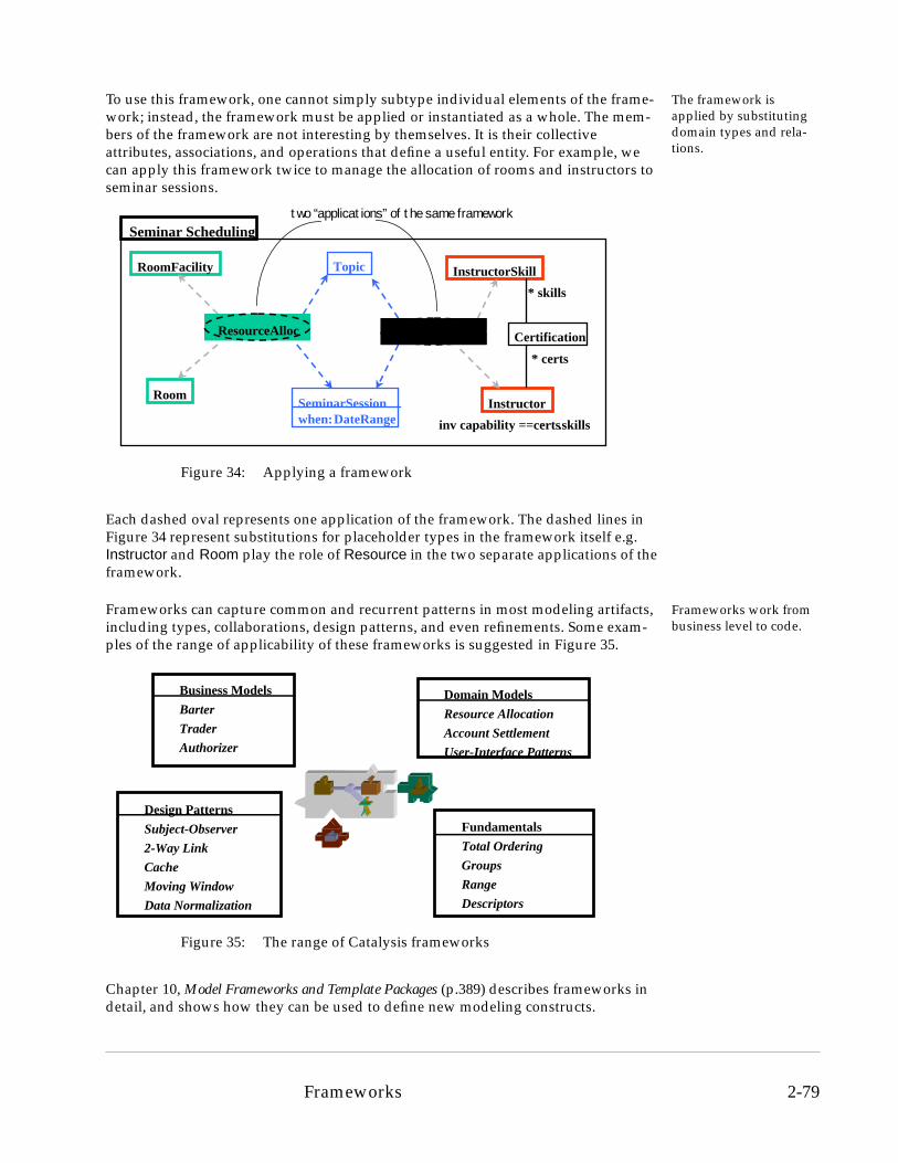
To use this framework, one cannot simply subtype individual elements of the frame-work; instead, the framework must be applied or instantiated as a whole. The mem-bers of the framework are not interesting by themselves. It is their collective attributes, associations, and operations that define a useful entity. For example, we can apply this framework twice to manage the allocation of rooms and instructors to seminar sessions.
Each dashed oval represents one application of the framework. The dashed lines in Figure 34 represent substitutions for placeholder types in the framework itself e.g. Instructor and Room play the role of Resource in the two separate applications of the framework.
Frameworks work from business level to code.
Frameworks can capture common and recurrent patterns in most modeling artifacts, including types, collaborations, design patterns, and even refinements. Some exam-ples of the range of applicability of these frameworks is suggested in Figure 35.
Chapter 10, Model Frameworks and Template Packages (p.389) describes frameworks in detail, and shows how they can be used to define new modeling constructs.
Figure 34: Applying a framework
Topic
SeminarSessionwhen: DateRange
Room
RoomFacility
Instructor
InstructorSkill
inv capability == certs.skills
Certification
* skills
* certs
ResourceAlloc ResourceAlloc
Seminar Schedulingtwo “applications” of the same framework
Figure 35: The range of Catalysis frameworks
Business Models
Barter
Trader
Authorizer
Domain Models
Resource Allocation
Account Settlement
User-Interface Patterns
Design Patterns
Subject-Observer
2-Way Link
Cache
Moving Window
Data Normalization
Fundamentals
Total Ordering
Groups
Range
Descriptors
Frameworks 2-79

2.9 The Software Development Process
A idealized development process must be adapted to situation specifics
The Catalysis software development process is similar to that proposed by some other object-oriented methods. In practice, it also has an opportunistic element. The activi-ties of the process may be exercised in different orders, based on factors such as project management decisions (e.g., division of labor), understanding of the problem (e.g., one area of the problem may proceed to implementation while another is still being analyzed), risk-management decisions (e.g. early prototypes to test the technical architecture). The Catalysis process is presented here as an idealized process, as if a project could be developed from conception to completion without making an error (what a fantasy!), whether conceptual, structural, or technological.
There are just 3 primary levels.
The Catalysis process is divided into three levels of development: the problem domain or business level, the component specification level, and the component design level. Section 2.9.4 will outline how these three basic levels of development correspond to separate activities when developing a typical business-application, including its user-interface and database.
“external vs. internal” is clearer than “analysis vs. “design”
The terms “analysis” and “design” are usually very vaguely defined, with analysis having to do more with the problem or “what”, and design being more concerned with the “how”. Because their definitions are fuzzy, it easy to get into fruitless discus-sions about what activities are analysis and design. It is more helpful to start with a distinction between “external” decisions — any decision, no matter how high-level or detailed, that is significant to an external software component, or human user; and “internal” decisions — any decision that is irrelevant to an external client. The former we call “specification”, the latter we call “internal design”, or “implementation”.
There is always an ele-ment of “external” or “business” design
Loosely, analysis is concerned about external issues, starting from identifying and understanding the problem, to specifying each component of an envisioned solution; design about internal decisions. However, externally visible decisions will often have some design flavor; we consider these to constitute “external design” or “business design”. Chapter 14, Process Overview (p.521) will discuss the relationship with more traditional terms, such as “analysis” and “design”, in some more detail.
2.9.1 Problem Domain or Business Level: the “Outside”
The goal is to clarify problem domain terms
At the problem domain or business level the emphasis is on understanding the prob-lem domain and how the system to be developed fits into the problem domain. For the sake of brevity, this level is referred to as the problem domain level.
Storyboards and mind-maps for brainstorming
Many projects can benefit from early brainstorming tech-niques applied to the problem domain itself. These include storyboards (sketches of different situations and scenarios in the problem domain) and mind-maps (a structured representa-tion of related terms). The problem domain includes any tar-get system itself and its environment. The mind map is a
concise representation of the important concepts of the problem domain. The notation for the mind map is simply concepts or phrases with lines between them, and can include rich pictures or storyboards based on the domain. The concepts may be verbs,
call phone
caller service
has
receiversymptom
2-80 The Software Development Process

nouns, or phrases. If desired, one may place a term and direction on a line to clarify its meaning. The notation has no deeper semantic meaning than two concepts connected by a line are in some way related to each other. However, the mind-map can easily be evolved into a problem domain collaboration model. Creating a mind map helps identify the terminology of the problem domain.
Formal domain collabo-ration model — as-is and to-be
Once some of the terminology has been established one can create a problem domain collaboration model. This model identi-fies the actors in the domain (those who do something) and their interactions (their actions, or use-cases, and information exchanged). The actors typically represent the roles of people (e.g., buyer) or software systems (e.g., inventory system). There are two types of problem domain collaboration models that one might be interested in creating: an “as-is” model or a “to-be” model. The “as-is” model describes the problem domain (or business) as it currently exists. The “to-be” model describes the problem domain (or business) as it is intended to be when the new system(s) are implemented. These two models also form the basis of deployment and transition plans for the systems.
System context for com-ponent of interest
Having established the new problem domain, one needs to define the scope of a given system or component to be devel-oped. This is accomplished by creating a system context dia-gram. A system context diagram is a collaboration model in which the system to be developed is portrayed as one of the actors, and every external actor and action is shown, at least at an abstract level. This helps precisely define the boundaries of what will be called “the system”. The actions in which the system is an actor are those that must be developed as part of the system.
Scenarios provide con-crete usage paths
To aid in developing the above collaboration models a devel-oper might find it useful to define some scenarios, each of which would illustrate a sequence in which the actions take place. And often, the development of the scenarios aids in identifying actions that have not yet been depicted in the col-laboration model. It is possible, and often very helpful, to formalize the actions using the same techniques of scenarios, snapshots, and a type model, as are used in Section 2.9.2. This yields problem domain terminology that is already considerably “debugged”, simplifying downstream work.
2.9.2 Component Specification Level: the “Boundary”
We want a precise behav-ior specification
At this level we want to describe the externally visible behavior of the system unam-biguously. We could be describing either a small or large component, or a complete system. The desired result is a specification of the interface(s) of the system.
The entire system is spec-ified as a type
The starting point for component specification is the system context diagram of the problem domain level. The system being developed is represented as a type, where a type con-sists of a type model and a set of operations on that type model. The initial definition of the type involves identifying each action in which the system to be developed participates and
abcdefghijkl
Type
1 *
The Software Development Process 2-81

specifying it as an operation on the type. It is likely that these operations will be refined into multiple operations during the development of the system specification, as is common with a use-case driven approach.
Complex systems are also partitioned by sub-ject areas
For complex systems we need some basis to factor out the specification itself into sep-arate parts and to meaningfully structure the analysis effort and documentation. We use the concept of a subject area — a broad area of usage or function that helps parti-tion the system behavior, so that one area may be analyzed somewhat separately from the others. A system operation will usually be assigned to one subject area. If an oper-ation appears in two subject areas, each describes just the effects of the operation within that subject area. Subject areas let us separate different aspects or qualities of the requirements, structuring a specification document into more focused sections that separate different constraints on behavior based on the nature of constraint rather than what is being constrained. Subject areas in analysis will not necessarily be imple-mented as separate components.
Operations are specified informally, at first.
For each operation that has been identified one writes an informal specification in which one indicates (a) the inputs required by the operation, (b) the changes in the object itself and outputs returned to the initiator or sent to outside actors, and (c) the conditions under which the behavior is guaranteed.
The specification is for-malized in systematic steps.
After developing an informal specification for an operation, one proceeds to formalize the specification. To formalize an operation, one does the following:
• Identify inputs and outputs — returned values or sent events.
• Identify attributes — terms used in the specification of the operations that are either derived from inputs to the operation, or presumed part of the state of the component itself. Attributes represent an abstraction of the state of that object and of any information exchanged with it.
• Identify types for input parameters, output parameters, and attributes based upon what you need to say about them in the operation specification.
• Formalize the operation specification to specify outputs and state changes in attributes strictly in terms of inputs and object attributes.
• Review and improve the informal specification.
An implementation-independent model
The attributes of the type are described as model types, with attributes and associa-tions between model types, and invariants that relate valid values of attributes. The associations have a cardinality to indicate the multiplicity of one model type relative to another. Operations are specified precisely in terms of these attributes, but neither the attributes nor the operation specifications represent implementation decisions.
Scenarios and snapshots help build the model
To aid in the development of the system specification it is helpful to develop scenarios, which can be depicted as sequence diagrams. A sequence diagram illustrates a specific ordering of interactions. To aid in identifying how the attributes of the system are affected by an operation one can create a series of snapshots. A snapshot shows the subset of attribute values presumed to exist before an operation, or
resulting upon completion of an operation. By looking at two snapshots, one from before the execution of an operation and one after the execution of an operation, it
actor actorsystem
2-82 The Software Development Process
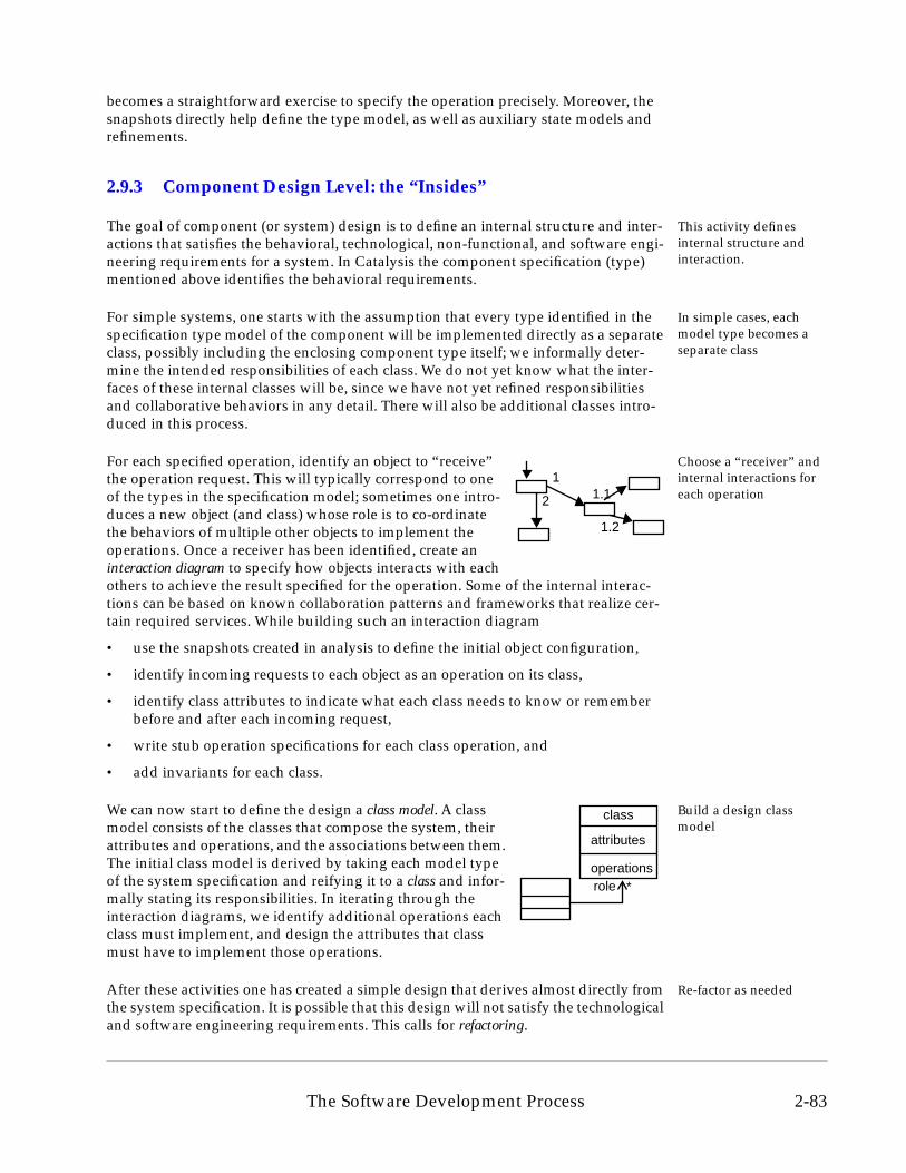
becomes a straightforward exercise to specify the operation precisely. Moreover, the snapshots directly help define the type model, as well as auxiliary state models and refinements.
2.9.3 Component Design Level: the “Insides”
This activity defines internal structure and interaction.
The goal of component (or system) design is to define an internal structure and inter-actions that satisfies the behavioral, technological, non-functional, and software engi-neering requirements for a system. In Catalysis the component specification (type) mentioned above identifies the behavioral requirements.
In simple cases, each model type becomes a separate class
For simple systems, one starts with the assumption that every type identified in the specification type model of the component will be implemented directly as a separate class, possibly including the enclosing component type itself; we informally deter-mine the intended responsibilities of each class. We do not yet know what the inter-faces of these internal classes will be, since we have not yet refined responsibilities and collaborative behaviors in any detail. There will also be additional classes intro-duced in this process.
Choose a “receiver” and internal interactions for each operation
For each specified operation, identify an object to “receive” the operation request. This will typically correspond to one of the types in the specification model; sometimes one intro-duces a new object (and class) whose role is to co-ordinate the behaviors of multiple other objects to implement the operations. Once a receiver has been identified, create an interaction diagram to specify how objects interacts with each others to achieve the result specified for the operation. Some of the internal interac-tions can be based on known collaboration patterns and frameworks that realize cer-tain required services. While building such an interaction diagram
• use the snapshots created in analysis to define the initial object configuration,
• identify incoming requests to each object as an operation on its class,
• identify class attributes to indicate what each class needs to know or remember before and after each incoming request,
• write stub operation specifications for each class operation, and
• add invariants for each class.
Build a design class model
We can now start to define the design a class model. A class model consists of the classes that compose the system, their attributes and operations, and the associations between them. The initial class model is derived by taking each model type of the system specification and reifying it to a class and infor-mally stating its responsibilities. In iterating through the interaction diagrams, we identify additional operations each class must implement, and design the attributes that class must have to implement those operations.
Re-factor as neededAfter these activities one has created a simple design that derives almost directly from the system specification. It is possible that this design will not satisfy the technological and software engineering requirements. This calls for refactoring.
1
2 1.1
1.2
class
attributes
operations*role
The Software Development Process 2-83

Design re-factoring improves the design
Refactoring a design requires many activities, some of which might correspond to conflicting goals (e.g., the old time vs. space trade-off, re-use of existing components). Some refactoring activities that one might consider are:
• Factor all the operations of an object into different views for different clients. Define each view as a separate type. Write specifications for each type.
• Migrate common operations and related data into super-classes or delegatee classes.
• Decide if one class will implement all those types or many linked classes.
• Distinguish essential dependencies vs. alternate co-ordination mechanisms.
• Define components, with services provided, required, and events raised.
• Extract patterns of interactions as collaborations between types.
• Identify variation points; separate into a distinct object and compose.
• Refactor common code into composed classes or superclasses.
One might do all or none of the above refactoring activities depending on the require-ments of their project. After refactoring, one should have a design that is easily imple-mentable using the technologies selected by the project (e.g., programming language, distributed computing paradigm, persistent storage paradigm, etc.).
Complex systems will first be partitioned into larger components
In the case of complex systems, design will typically proceed in stages. We might first factor the system into large-grained components, based on considerations such as those in Section 2.5.2. We design the initial interactions between these components and specify each of their interfaces as a type with a type model. This design can then be related back to the external specification type model; it should constitute a valid refinement, and we can map from the design to the specification. Individual compo-nents are specified and designed internally in a recursive manner.
2.9.4 Typical Large Business Systems
A typical large business system will have human users and a back-end database. The development process for these systems still goes through the levels outlined earlier, but there are some specific activities that are commonly required within the levels.
User-Interface design starts early.
Figure 36 outlines some of these distinct activities, and how they map to the three essential levels we discussed. The domain level is similar to before, focused on build-ing a clear, precise glossary of problem domain terms. System specification proceeds much as before, but has an added element of user-interface design. The normal arti-facts of system specification — a type model and operation specs — are now accom-panied with prototypes of user-interfaces, illustrating the screens, dialog flows, and information presented and required, for general usability testing. These user-interface bits are kept consistent with the type-model and reviewed through the scenarios. Detailed design of the screens and widgets comes much later.
2-84 The Software Development Process

Technical architecture is a separate concern.
The design of a system or large component is often broken into separate levels. The technical architecture issues — hardware and software platforms and tools, infra-structure components such as middle-ware and data-bases, the choice of standards to conform to, such as applications-management interfaces, and the choice of component architecture, such as JavaBeans or COM — are decided, after careful evaluation against requirements such as throughput, scalability and response time.
Application architecture is high-level design
The application architecture is the design of application logic itself as a collection of collaborating components, with the original specification model types now split across different components. These components may range from custom-built to com-mon off-the shelf components such as spread-sheets, calendars, and contact-manag-ers, to purchased domain-specific components like factory-floor schedulers.
Database design is a sep-arate activity
The design of the database portion should start at this stage, and includes mapping of the design object model, transaction boundaries, etc. Depending upon the choice of database and supporting tools in the technical architecture, this initial activity may or may not take significant effort. Database performance tuning, however, will usually take some effort.
And the overall process is recursive, as before.
Individual application components are designed and built down to the level of pro-gramming language interfaces and classes, pre-existing components, or to a point where the implementation can be mechanically generated from the detailed design.
Figure 36: Development process for typical business system
RequirementsRequirements Domain ModelsDomain Models
System ContextSystem ContextUnderstand the business problem,system context and requirements.
System SpecificationSystem Specification ScenariosScenarios
Type Model and Op SpecsType Model and Op SpecsDescribe external behavior of target system using problem domain model
Architectural DesignArchitectural Design Platform, Physical ArchitecturePlatform, Physical Architecture
Logical Application ArchitectureLogical Application Architecture
Partition technical and applicationarchitecture components and their connectors to meet design goals
UI DesignUI Design
dialog flow, prototype, usability
DB DesignDB Design
class mapping,transactions, etc.
Component Internal DesignComponent Internal Design
Design interfaces and classes for each component; build and test
Interface and Class SpecsInterface and Class Specs
Implementation and TestImplementation and Test
Dictio
nary
Dictio
nary
domain/busines
component spec
component desi
The Software Development Process 2-85

2.10 Catalysis in Perspective
What problems are addressed?
Catalysis has addressed some of the challenges facing object and component-based development. This section outlines some of the problems addressed.
Data-driven vs. Behavior-driven Approaches
There is no conflict between these two in Catalysis
Our approach to defining a type solves the long-standing controversy between behav-ior-driven and data-driven methodologies. Several methods, including OMT and the UML, have been criticized by “behaviorists” for what is perceived as a data-centric approach. Using our approach this becomes a non-issue. In Catalysis these two views are inseparable. In order to describe the behavior of a component you will need an underlying vocabulary for its state and for any information exchanged with it, which should relate to clients’ concerns rather than any implementation. Formalize this vocabulary as a type model model in terms of a set of attributes.
Thus, in Catalysis, specification of behavior will always uncover a corresponding abstract type model of ‘data’; conversely, and description of ‘data’, no matter how abstract or concrete, should be justified by some requirement on externally visible behavior. Any correct implementation will have some mapping from its concrete rep-resentation choices to the attributes in the type-model.
Component based development
Components of any scales are supported
Catalysis enables component based development in a couple of different ways. Firstly, Catalysis can characterize an object of any size as an object, entirely independent of its internal implementation, without any loss of precision in the interface specification. Multiple interfaces of a component can be described readily, using type models suited to each interface. And the component specifications are precise enough to be used as the basis of a test specification; a correct implementation can be shown to map to the specification.
You can re-use and com-pose more than code
Secondly, components are not merely about pieces of code. They can include models, designs, specifications, and frameworks — any encapsulated units that can be com-posed with others. Catalysis permits any coherent unit of design work to be pack-aged, and to be made generic to enable re-use in many different situations. Collaborations in Catalysis permit architectural elements to be re-used across differ-ent applications. The technology of model frameworks in Catalysis provdies a way to characterize recurring patterns at all levels of development.
Activity-driven Modeling
From activities to APIs using refinement
The focus on abstract actions and collaborations in Catalysis lets you describe interac-tions independent of detailed protocols between participants or API level calls between software systems. This, combined with the ability to defer details about initi-ators and receivers of action requests, lets us focus on high-level actions, even at the
2-86 Catalysis in Perspective

level of business activities. The ability to refine permits a seamless transition from activity models, through component interfaces, and to the internal designs of compo-nents.
Traceability from Requirements to Code
Precise abstraction enables traceability
Catalysis support for refinement lets you separate abstract models from their many possible realizations. The abstract descriptions typically defer internal structure or algorithmic sequences of interactions of a component, or details of interaction dialogs and responsibilities of different parties. The abstract models are still precise enough to be traced to, and even refuted or defended, against concrete realizations.
Re-use of Design Patterns and Frameworks
Recurring patterns: abstract and re-apply
Recurring patterns of all kinds — including design patterns, specifications, problem domain specific requirements, and typical refinements and their mappings — can be characterized as frameworks in Catalysis. The abstract descriptions can, again with-out loss of precision, be used in different situations and applications by adapting them to a particular problem and ‘applying’ the framework.
Practical Rigor
Early avaibility of rigor when needed
Rigor and precision is not an end in itself. However, Catalysis practitioners know that when it is judiciously practiced, it can uncover critical questions and issues that would otherwise have gone unnoticed until coding or testing. All diagrams in Cataly-sis have precise semantics, and can be translated into a textual equivalent. And effec-tive abstraction is achieved without resorting to the dangerous fuzziness that often accompanies high-level ‘analysis’ and ‘architecture’ descriptions.
Practical Tool Support
Tool support beyond drawings
Last, but not least, Catalysis enables a new level of tool support for standard notations and diagrams. The semantics of the diagrams, and the clear underlying relationships between different diagrams at the same or different levels of abstraction, combined with the definition of refinement relationships between parts, makes it practical for development tools to support much more than just drawings and document genera-tion. The systematic nature of Catalysis development, with its clear separation and relationship between artifacts, makes it possible to also use currently popular object-modeling UML tools on a Catalysis process by simply following simple usage guide-lines.
2.10.1 Catalysis and Standards
Catalysis has contributed to current standards
The Unified Modeling Language (UML) and metamodel has adopted significant modeling constructs from Catalysis, including types, behavior specifications, refine-ments, collaborations, and frameworks. Catalysis has also contributed to the IBM interoperability metamodel submitted to the OMG, and to the OPEN project. The appendices contain a section discussing the relationship between Catalysis and UML.
Catalysis in Perspective 2-87

Applying a use-case driven development process is also discussed in Chapter 5, Interac-tion Models — Use Cases, Actions, and Collaborations (p.205), as well as in Section VI, How To Apply Catalysis (p.519).
The Catalysis approach complements the viewpoint-based separation advocated by the RM-ODP standards, due to its basis on refinement, and the ability to ‘join’ multi-ple partial definitions of the same, or overllaping, phenomena.
The following table shows what Catalysis adds with respect to several object-oriented analysis and design methods.
2.10.2 Catalysis Support
The following table shows what support is currently available for the Catalysis method as of late 1997, when there were several projects using the method.
With Respect To Catalysis Adds
OMT Full Model Consistency, Views and Pattern Synthesis, Multiple Types per Object, Rigor and Refinement, Architectural Components.
Fusion Full Model Consistency, Views and Pattern Synthesis, Multiple Types per Object, Rigor and Refinement, Architectural Components, Inte-grated State Modeling.
Booch Full Model Consistency, Views and Pattern Synthesis, Multiple Types per Object, Rigor and Refinement, Architectural Components, Anal-ysis and Specification.
Objectory Formalization of Use-case, Rigor and Refinement, Multiple Types per Object, Views and Pattern Synthesis.
UML Simple and consistent core, Model Consistency, Views and Pattern Synthesis, Rigor and Refinement, Architectural Components, Frame-works, Precise semantics, Development Process.
Tools Commercial tool support for notation and some consistency checks, with more complete semantic support following. Cataly-sis enables a new level of tool support for synthesizing, tracing, and re-using modeling frameworks at all levels.
Literature Case studies, meta-model, reference cards, semantics, published papers, text book, extensive on-line information on the Catalysis web-site.
Consulting, Training Full-length training courses, consulting and mentoring support, and immersion programs. Train-the-trainer and course licensing also available.
Project Experience Used successfully on projects ranging from real-time systems, manufacturing automation, information management systems, desktop business applications, and enterprise modeling.
2-88 Catalysis in Perspective

2.11 Summary
The Catalysis software development method is based on the principles of abstraction, precision, and pluggable components. These principles can be applied at all levels of software development from problem domain or business modeling through system design and implementation.
The constructs of Catalysis — types, collaborations, and refinement — support the separation of interface from implementation, which enables the method to describe components (objects) and systems independent of their implementation. These con-structs also facilitate the description of frameworks, which can be plugged in to busi-ness models, analysis models, design models, or implementations. The constructs can be used at all levels of software development. Refinement through multiple abstrac-tions and realizations ensures that an implementation conforms to the description of a problem domain or business. And Catalysis frameworks provide a powerful tool to extract and re-use recurring patterns at all levels of description.
The Catalysis process in practice will always be somewhat opportunistic. There is no prescribed order in which the activities of the Catalysis process must be undertaken, although skeletal steps provide a good reference point, and different ‘reference’ paths may be tailored to different project needs. However, at all times the relationships between the project artifacts are well defined, and consistency criteria can be used for reviews, inspections, and automated checking. On completion of a project the artifacts should demonstrate traceability (via refinement and conformance) from the problem domain (business) models to the implementation.
Catalysis compares favorably with other object-oriented methods. It supports features of other recent methods while adding more abstract and expressive features to better support building systems using distributed components and frameworks, as well as providing the clear separation of concerns that becomes important for rapid iterative application development. It does this while retaining a simple and small core.
Catalysis artifacts can be described using the Unified Modeling language (UML) nota-tion. So, tools that support UML can be used to develop Catalysis artifacts. However, Catalysis enables a much higher level of tool support than that provided by most cur-rent tools.
Summary 2-89

2-90 Summary