Embed Size (px)
Citation preview
CHAPTER 2
BASIC ADMINISTRATION AND TRAINING Every time you advance in pay grade, you increase your responsibility for administration and training. This chapter deals briefly with some of your administrative responsibilities and then touches on certain aspects of your responsibility for training others.
LEARNING OBJECTIVES When you have completed this chapter, you will be able to do the following:
1. Describe the procedures for preparing fuel, oil, and water reports. 2. Explain the procedures for drawing fluid samples. 3. Describe Engineering Operational Sequencing System (EOSS) manuals. 4. Describe Engineering Operational Procedures (EOPs.) 5. Describe Engineering Operational Casualty Control (EOCC.) 6. Explain the Quality Assurance (QA) Program.
ENGINEERING RECORDS AND LOGS As an Engineman (EN), you will be primarily concerned with updating logs and similar records. Some of the logs and records are official, legal records. Others are used to upkeep the ship’s equipment. The standard forms for the logs and records are prepared by the various systems commands and the Chief of Naval Operations (CNO). The forms are for issue to forces afloat and are available as indicated in the Unabridged Navy Index of Publications and Forms, NPFC PUB 2002 D. These forms are revised as conditions warrant and personnel ordering them must be sure they order the most current forms. If you need similar forms for local use, ensure that an existing standard form will not serve the purpose before you request that a special form be prepared and printed.
Legal Engineering Records The Engineering Log and the Engineer’s Bell Book are the only legal records compiled by the engineering department. The Engineering Log is a midnight-to-midnight record of the ship’s engineering department. The Engineer’s Bell Book is a legal record of any orders regarding change in the movement of the propellers.
Engineering Log The Engineering log is a complete daily record which covers important event and data pertaining to the Engineering Department and the operation of the ship’s propulsion plant. The log must show the following information:
1. The total engine miles steamed for the day 2. Draft and displacement upon getting underway 3. The disposition of the engines, boilers, and principal auxiliaries and any changes in their
disposition 4. Any injuries to engineering department personnel 5. Any casualties to engineering department machinery, equipment, or material
6. Other matters specified by competent authority Depending on your training and watch position, you may have to either make entries in the Engineering Log or both make and verify such entries. Whatever the case, each entry must be made according to instructions given in (1) the Engineering Log, NAVSHIPS 3120/2D; (2) the Naval Ships’ Technical Manual (NSTM), Chapter 090; and (3) directives issued by the type commander (TYCOM). Each entry must be a complete statement using standard phraseology. The TYCOM’s directives may contain other specific requirements pertaining to the Remarks section of the Engineering Logs for ships of the type. The original Engineering Log, prepared neatly and legibly in ink, is a legal record. Do NOT keep a rough log. Keep the Engineering Log current. Enter each event onto the Engineering Log as it happens. No erasures are permitted in the log. When a correction is necessary, draw a single line through the original entry so that the entry remains legible. The correct entry must be clear and legible. Corrections, additions, or changes are made only by the person required to sign the log for the watch this person then initials the margin of the page. The engineering officer of the watch (EOOW) should prepare the remarks for the log and should sign the log before being relieved at the end of the watch or duty day. The engineer officer verifies the accuracy and completeness of all entries and signs the log daily. The log sheets must be submitted to the engineer officer in time to allow him or her to check and sign them before noon of the day following the date of the log sheet(s). The commanding officer (CO) approves the log and signs it on the last calendar day of each month and on the date he or she relinquishes command. Completed pages of the log, filed in a post-type binder, are numbered consecutively. They begin with the first day of each month and run through the last day of the month. When the CO (or engineer officer) directs a change or addition to the Engineering Log, the person directed must comply unless he or she believes the proposed change or addition to be incorrect. In that event, the CO or engineer officer will personally enter comments and sign the log. After the log has been signed by the CO, it may not be changed without his or her permission or direction.
Engineer’s Bell Book The Engineer’s Bell Book, NAVSHIPS 3120/1, is a record of all bells, signals, and other orders received by the throttleman for movement of the ship’s propellers. Entries are made in the Bell Book by the throttleman (or an assistant) as soon as an order is received. Entries are usually made by the assistant when the ship is entering or leaving port, or engaging in any maneuver that is likely to involve numerous or rapid speed changes. This procedure allows the throttleman to devote his or her undivided attention to answering the signals. The Bell Book is maintained in the following manner:
1. A separate bell sheet is used for each shaft each day, except where more than one shaft is controlled by the same throttle station. In that case, the same bell sheet is used to record the orders for all shafts controlled by the station. All sheets for the same date are filed together as a single record.
2. The time of receipt of the order is recorded in column number 1. 3. The order received is recorded in column 2. Minor speed changes (generally received via
revolution indicator) are recorded by entering the number of revolutions per minute (rpm) ordered. Major speed changes (normally received via engine order telegraph) are recorded using the following symbols:
a. 1/3: ahead 1/3 speed b. 2/3: ahead 2/3 speed
c. I: ahead standard speed d. II: ahead full speed e. III: ahead flank speed f. Z: stop g. B1/3: back 1/3 speed h. B2/3: -back 2/3 speed i. BF: back full speed j. BEM: back emergency speed
4. The number of revolutions corresponding to the major speed change ordered is entered in column 3. When the order received is recorded as rpm in column 2 (minor speed changes), no entry is made in column 3.
5. The shaft revolution counters reading (total revolutions) at the time of the speed changes is recorded in column 4. The shaft revolution counter reading—as taken hourly on the hour while underway—also is entered in column 4.
For ships and craft equipped with controllable reversible pitch propellers, the propeller pitch in feet and fractions of feet set in response to a signaled speed change, rather than the shaft revolution counter readings, is recorded in column 4. The entries for astern pitch are preceded by the letter B. Each hour, on the hour, entries are made of counter readings. These entries help in calculating engine miles steamed during the time the propeller pitch remained constant at the last value set in response to a signaled order. On ships with gas turbine propulsion plants, a bell logger provides an automatic printout each hour. This printout is also provided whenever propeller rpm or pitch is changed by more than 5 percent, when the engine order telegraph is changed, or when the controlling station is shifted. Provision must be made for manual logging of data in the event the bell logger is out of commission (OOC). Before going off watch, the EOOW signs the Bell Book on the line following the last entry for his or her watch. The next officer of the watch continues the record immediately thereafter. In machinery spaces where an EOOW is not stationed, the bell sheet is signed by the watch supervisor.
The Bell Book is maintained by bridge personnel in ships and craft equipped with controllable reversible pitch propellers and those in which the engines are directly controlled from the bridge. When control is shifted to the engine room, however, the Bell Book is maintained by the engine-room personnel. The last entry made in the Bell Book on the bridge shows the time that control is shifted. The first entry made in the Bell Book in the engine room shows the time that control is taken by the engine room. Similarly, the last entry made by engine-room personnel show when control is shifted to the bridge. When the Bell Book is maintained by the bridge personnel, it is signed by the officer of the deck (OOD). Alterations or erasures are not permitted in the Bell Book. An incorrect entry is corrected by drawing a single line through the entry and recording the correct entry on the following line. Deleted entries are initialed by the EOOW, the OOD, or the watch supervisor, as appropriate.
NOTE A common practice is to have the throttleman sign the Bell Book before it is signed by the EOOW or his or her relief.
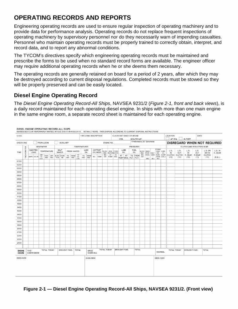
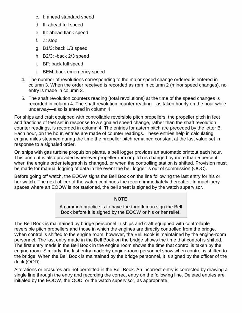
Figure 2-1 — Diesel Engine Operating Record-All Ships, NAVSEA 9231/2. (Front view)
OPERATING RECORDS AND REPORTS Engineering operating records are used to ensure regular inspection of operating machinery and to provide data for performance analysis. Operating records do not replace frequent inspections of operating machinery by supervisory personnel nor do they necessarily warn of impending casualties. Personnel who maintain operating records must be properly trained to correctly obtain, interpret, and record data, and to report any abnormal conditions. The TYCOM’s directives specify which engineering operating records must be maintained and prescribe the forms to be used when no standard record forms are available. The engineer officer may require additional operating records when he or she deems them necessary. The operating records are generally retained on board for a period of 2 years, after which they may be destroyed according to current disposal regulations. Completed records must be stowed so they will be properly preserved and can be easily located.
Diesel Engine Operating Record The Diesel Engine Operating Record-All Ships, NAVSEA 9231/2 (Figure 2-1, front and back views), is a daily record maintained for each operating diesel engine. In ships with more than one main engine in the same engine room, a separate record sheet is maintained for each operating engine.
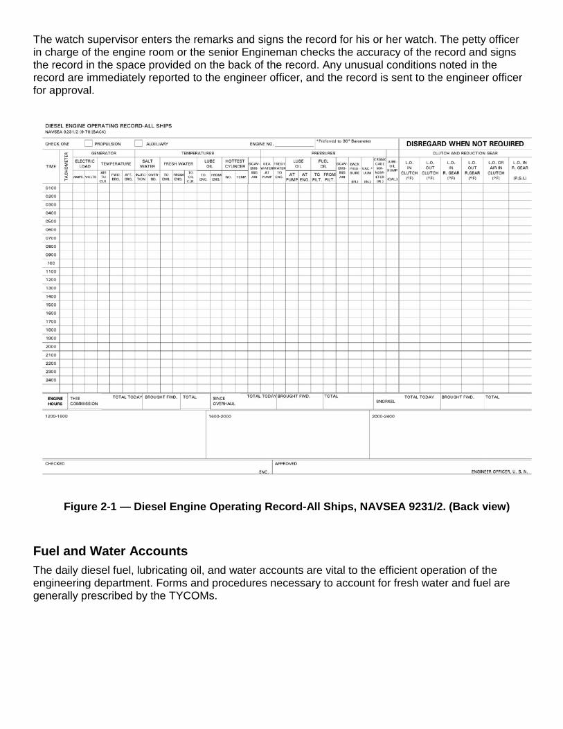
Figure 2-1 — Diesel Engine Operating Record-All Ships, NAVSEA 9231/2. (Back view)
The watch supervisor enters the remarks and signs the record for his or her watch. The petty officer in charge of the engine room or the senior Engineman checks the accuracy of the record and signs the record in the space provided on the back of the record. Any unusual conditions noted in the record are immediately reported to the engineer officer, and the record is sent to the engineer officer for approval.
Fuel and Water Accounts The daily diesel fuel, lubricating oil, and water accounts are vital to the efficient operation of the engineering department. Forms and procedures necessary to account for fresh water and fuel are generally prescribed by the TYCOMs.
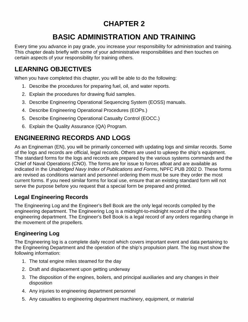
Figure 2-2 — Fuel and Water Report, NAVSEA 9255/9.
Fuel and Water Reports The Fuel and Water Report, NAVSEA 9255/9 (Figure 2-2, frames 1 and 2), is a report submitted daily to the CO. This report indicates the amount of fuel oil and water on hand as of midnight. The Fuel and Water Report also includes the previous day’s feed and potable water consumption figures and results of water tests. The original and one copy are submitted to the OOD in sufficient time for submission to the CO or command duty officer with the 1200 reports. The copy is retained by the OOD.
Daily Boat Fueling Record The Daily Boat Fueling Record is a routine record of daily fueling, which is highly recommended for any ship that carries or maintains a number of boats. Use of this schedule will help prevent special fueling at unusual hours and will keep the boats ready for unexpected calls. The following list contains the recommended headings for this record:
• Boat number
• Fuel capacity in gallons
• Gallons on hand
• Approximate fuel consumption in gallons per hour
• Operating hours of fuel remaining
• Fueled or not fueled to capacity
Disposal of Engineering Records and Reports Before you destroy any of the engineering department records, study the Disposal of Navy and Marine Corps Records, USN and USNS Vessels, SECNAVINST P5212.5(series). This publication provides the procedures for disposing of records. For each department aboard the ship, these instructions list the permanent records that must be kept and the temporary records that may be disposed of according to an established schedule. Both the Engineering Log and Engineer’s Bell Book must be preserved as permanent records on board ship for a 3-year period unless they are requested by a naval court or board, or by the Navy Department. In such case, copies (preferably photostatic) of records that are sent from the ship are certified by the engineer officer as being true copies and are put in the ship’s files. At regular intervals, such as each quarter, records that are over 3 years old are destroyed. When a ship that is less than 3 years old is decommissioned, the current books are retained on board. If a ship is scrapped, the current books are forwarded to the nearest Naval Records Management Center. All reports forwarded to, and received from, Naval Sea Systems Command (NAVSEA) or another superior command may be destroyed when they are 2 years old, if they are no longer required. Finally, to control the volume of paper work, reports should only be kept on board ship if they
1. Are required, 2. Serve a specific purpose, or 3. May provide repair personnel with information not found in publications or manuals.
Equipment and Instrument Tag-Out Whenever you make repairs, you will be required to isolate and tag-out that equipment or section of the system. The program provides a procedure to be used when a component, piece of equipment, system, or portion of a system must be isolated because of some abnormal condition. The tag-out program also provides a procedure to be used when an instrument becomes unreliable or is not operating properly. The major difference between equipment tag-out and instrument tag-out is that tags are used for equipment tag-out and labels are used for instrument tag-out. Tag-out procedures are described in Standard Organization and Regulations of the U.S. Navy, OPNAVINST 3120.32(series), and represent the minimum requirements for tag-out. These procedures are mandatory and are standardized aboard ships and repair activities. The following definitions are used in the tag-out bill:
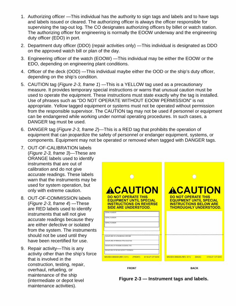
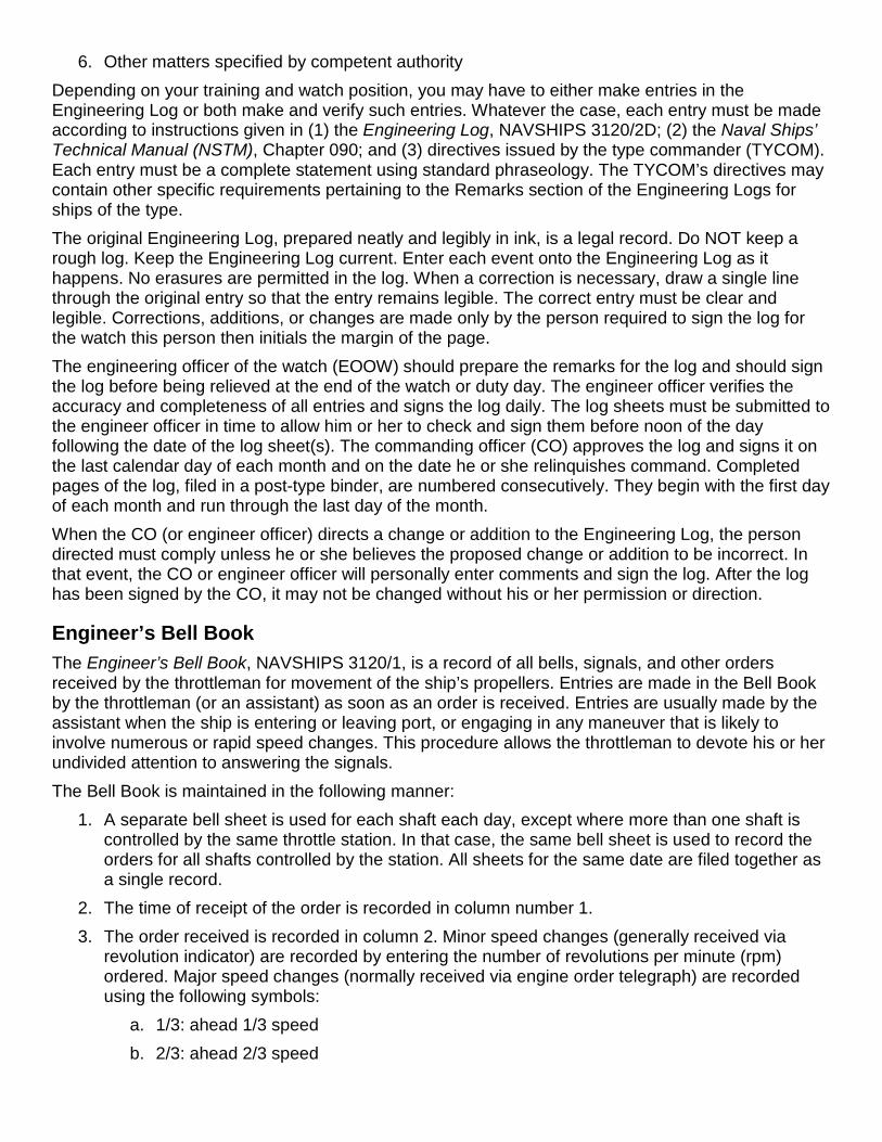
Figure 2-3 — Instrument tags and labels.
1. Authorizing officer —This individual has the authority to sign tags and labels and to have tags and labels issued or cleared. The authorizing officer is always the officer responsible for supervising the tag-out log. The CO designates authorizing officers by billet or watch station. The authorizing officer for engineering is normally the EOOW underway and the engineering duty officer (EDO) in port.
2. Department duty officer (DDO) (repair activities only) —This individual is designated as DDO on the approved watch bill or plan of the day.
3. Engineering officer of the watch (EOOW) —This individual may be either the EOOW or the EDO, depending on engineering plant conditions.
4. Officer of the deck (OOD) —This individual maybe either the OOD or the ship’s duty officer, depending on the ship’s condition.
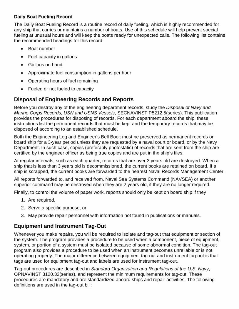
5. CAUTION tag (Figure 2-3, frame 1) —This is a YELLOW tag used as a precautionary measure. It provides temporary special instructions or warns that unusual caution must be used to operate the equipment. These instructions must state exactly why the tag is installed. Use of phrases such as “DO NOT OPERATE WITHOUT EOOW PERMISSION” is not appropriate. Yellow tagged equipment or systems must not be operated without permission from the responsible supervisor. The CAUTION tag may not be used if personnel or equipment can be endangered while working under normal operating procedures. In such cases, a DANGER tag must be used.
6. DANGER tag (Figure 2-3, frame 2)—This is a RED tag that prohibits the operation of equipment that can jeopardize the safety of personnel or endanger equipment, systems, or components. Equipment may not be operated or removed when tagged with DANGER tags.
7. OUT-OF-CALIBRATION labels (Figure 2-3, frame 3)—These are ORANGE labels used to identify instruments that are out of calibration and do not give accurate readings. These labels warn that the instruments may be used for system operation, but only with extreme caution.
8. OUT-OF-COMMISSION labels (Figure 2-3, frame 4) —These are RED labels used to identify instruments that will not give accurate readings because they are either defective or isolated from the system. The instruments should not be used until they have been recertified for use.
9. Repair activity—This is any activity other than the ship’s force that is involved in the construction, testing, repair, overhaul, refueling, or maintenance of the ship (intermediate or depot level maintenance activities).
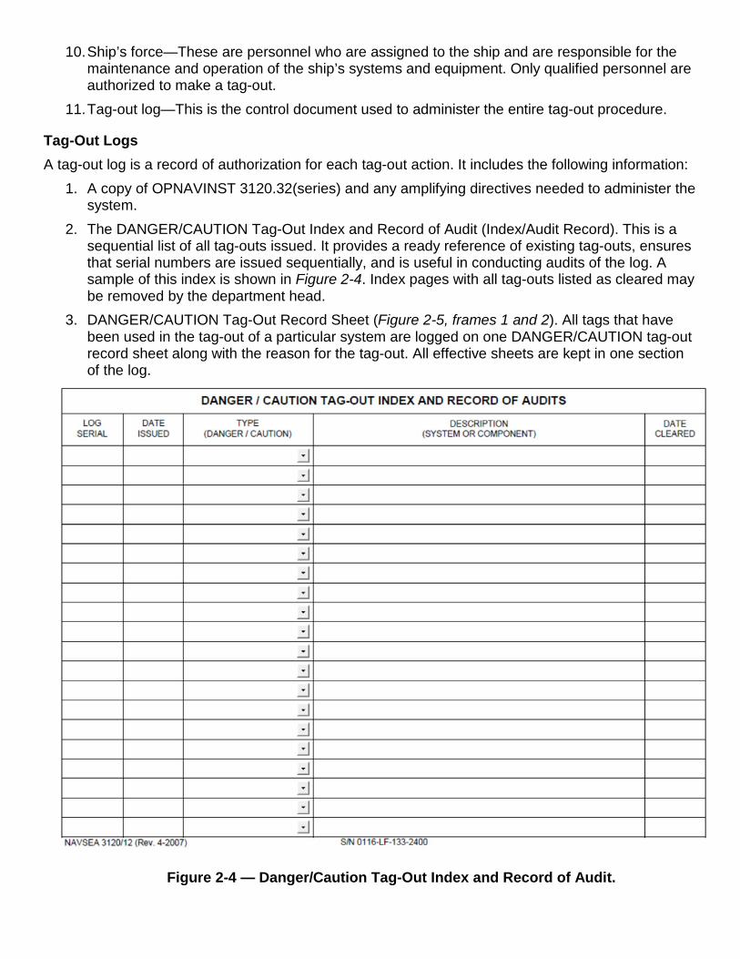
Figure 2-4 — Danger/Caution Tag-Out Index and Record of Audit.
10. Ship’s force—These are personnel who are assigned to the ship and are responsible for the maintenance and operation of the ship’s systems and equipment. Only qualified personnel are authorized to make a tag-out.
11. Tag-out log—This is the control document used to administer the entire tag-out procedure.
Tag-Out Logs A tag-out log is a record of authorization for each tag-out action. It includes the following information:
1. A copy of OPNAVINST 3120.32(series) and any amplifying directives needed to administer the system.
2. The DANGER/CAUTION Tag-Out Index and Record of Audit (Index/Audit Record). This is a sequential list of all tag-outs issued. It provides a ready reference of existing tag-outs, ensures that serial numbers are issued sequentially, and is useful in conducting audits of the log. A sample of this index is shown in Figure 2-4. Index pages with all tag-outs listed as cleared may be removed by the department head.
3. DANGER/CAUTION Tag-Out Record Sheet (Figure 2-5, frames 1 and 2). All tags that have been used in the tag-out of a particular system are logged on one DANGER/CAUTION tag-out record sheet along with the reason for the tag-out. All effective sheets are kept in one section of the log.
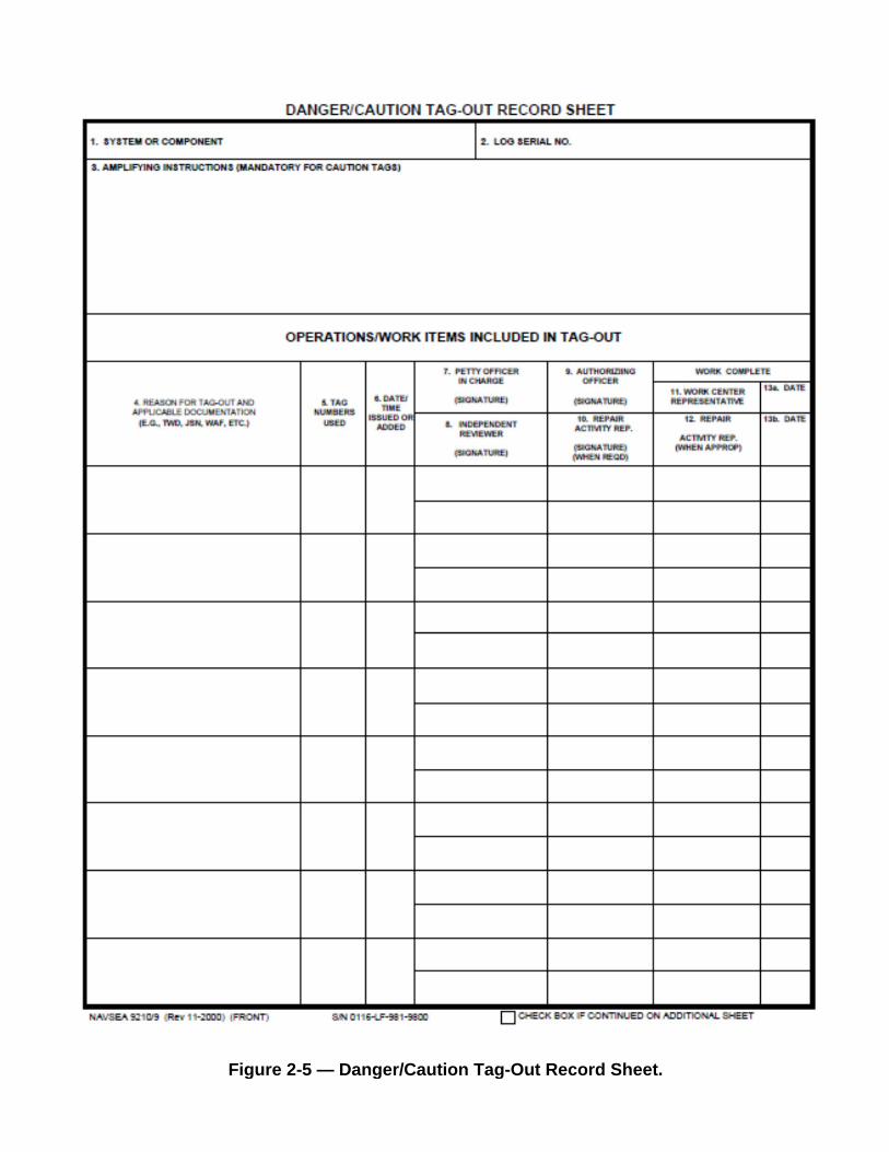
Figure 2-5 — Danger/Caution Tag-Out Record Sheet.
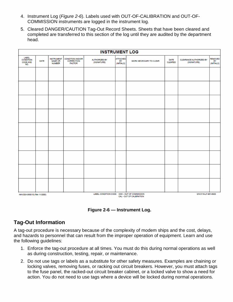
Figure 2-6 — Instrument Log.
4. Instrument Log (Figure 2-6). Labels used with OUT-OF-CALIBRATION and OUT-OF-COMMISSION instruments are logged in the instrument log.
5. Cleared DANGER/CAUTION Tag-Out Record Sheets. Sheets that have been cleared and completed are transferred to this section of the log until they are audited by the department head.
Tag-Out Information A tag-out procedure is necessary because of the complexity of modem ships and the cost, delays, and hazards to personnel that can result from the improper operation of equipment. Learn and use the following guidelines:
1. Enforce the tag-out procedure at all times. You must do this during normal operations as well as during construction, testing, repair, or maintenance.
2. Do not use tags or labels as a substitute for other safety measures. Examples are chaining or locking valves, removing fuses, or racking out circuit breakers. However, you must attach tags to the fuse panel, the racked-out circuit breaker cabinet, or a locked valve to show a need for action. You do not need to use tags where a device will be locked during normal operations.
3. Use tags to show the presence of, and the requirement for, freeze seals, blank flanges, or similar safety devices. When equipment or components are placed out of commission, use the tag-out procedures to control the status of the affected equipment. Examples are disconnecting electrical leads, providing jumpers, or pulling fuses for testing or maintenance.
4. Never use tag-outs to identify valves, to mark leaks, or for any purpose not specified in the tag-out procedure.
5. The absence of a tag or label may not be taken as permission for unauthorized operation of equipment.
6. Whenever a tag or label is issued, correct the situation requiring the tag or label so it can be removed as soon as possible.
7. The tag-out procedure is for use by the ship’s personnel on the equipment and systems for which they are responsible. However, repair activity personnel should use the procedure to the maximum extent practicable with systems and equipment that are still under construction.
8. Standard Organization and Regulations of the U.S. Navy, OPNAVINST 3120.32(series), is also required when work is being done by an intermediate level maintenance activity on equipment or systems that are the responsibility of the ship’s force. Sometimes a ship is under construction or assigned to a repair activity not under the control of the TYCOM. When that happens, the ship’s force and the repair activity may have to agree on the use of tags and labels. In this case, the tag-out system should be formal in nature and familiar to both the repair activity and the ship’s force.
9. Any person who knows of a situation requiring tags or labels should request that they be issued and applied.
10. When using labels, you should list on the log any associated requirements specified for installation procedures, test procedures, work permits (rip outs or reentries), or system turnover agreements.
11. Make each decision on a case-by-case basis as to whether an OUT-OF-COMMISSION or an OUT-OF-CALIBRATION instrument label is to be used. In general, if the instrument error is small and consistent, you can use an OUT-OF-CALIBRATION label and the operator may continue to use the instrument. When you use an OUT-OF-CALIBRATION label, mark on the label the magnitude and units of the required correction. However, when you use an OUT-OF-COMMISSION label, the instrument should not be used.
12. Use enough tags to completely isolate a section of piping or circuit being worked on, or to prevent the operation of a system or component from all stations that can exercise control. Use system diagrams or circuit schematics to determine the adequacy of all tag-out actions.
13. Careful planning of tag-outs can significantly reduce the number of record sheets and tags. Planning can also reduce the effort required to perform audits, particularly during periods of overhaul or repair. When you initiate the tag-out, include all known work items in the Operations/Work Items Included in Tag-Out section. If you add work items to a tag-out record sheet after initial issue, take the following action:
a. If no additional tags are required for the new work, have the authorizing officer and, if required, the repair activity representative makes sure the work is consistent with the purpose of the tag-out. New work must be fully described in the Operations/Work Items Included in Tag-Out section of the record sheet. The authorizing officer should make a thorough review to ensure the completeness and accuracy of the existing tag-out. This is the same procedure used to initiate a new tag-out record sheet for the added work. The authorizing officer (and repair activity representative) should sign the appropriate blocks next to the added item.
b. Additional tags may be needed to provide enough isolation for work that is to be added. If so, you must follow the procedures described later in this chapter for adding tags to an existing record sheet.
Procedures Assume that a requirement for tags has been identified, and that the affected system will be out of commission. The authorizing officer must ask the CO and department head for permission to begin the tag-out. Notify the responsible division officer of the requirement for tag-out. On ships having damage control central (DCC), the authorizing officer must notify DCC if the affected system or component will be out of commission. The Authorizing Officer should have approval from either the OOD or the EOOW if the tag-out will affect systems under their responsibility. PREPARING TAGS AND THE RECORD SHEET. DANGER and CAUTION tags and the associated tag-out record should be prepared as follows:
1. The person designated to prepare the tag-out is normally the ship’s force petty officer in charge of the work. He or she fills out and signs the record sheet and prepares the tags.
2. A tag-out record sheet is prepared for a specific purpose. All tags used for that purpose are listed on an initial record sheet and additional sheets as necessary. Each record sheet is assigned a log serial number in sequence, from the index/audit record. Log serial numbers are also used to identify all tags associated with a given purpose. Each tag is given its own sequential number as it is entered in the record sheet. For example, tag 7-16 would be the 16th tag issued on a single record sheet with the log serial number 7.
3. The tag-out record sheet includes references to other documents that apply. Some examples are work permits, work procedures, repair directives, reentry control forms, test forms, and rip-out forms. Certain information should be obtained either from reference documents or from the personnel requesting the work. Some examples are the reasons for tag-out, the hazards involved, the amplifying instructions, and the work necessary to clear the tags. This information should be detailed enough to give watch standers a clear understanding of the purpose of, and necessity for, each tag-out action.
4. Use enough tags to completely isolate the system, piping, or circuit being worked on. Be sure you use tags to prevent the operation of a system or component from all the stations that can exercise control. Use system diagrams or circuit schematics to determine the number of tags needed. Indicate the location and position/condition of each tagged item by an easily identifiable means. Some examples are MS-l, STBD TG BKR, OPEN, SHUT, BLANK FLANGE INSTALLED.
5. After you have filled out the tags and the tag-out record sheet, have a second person make an independent check of the tag-out coverage and usage. That person should use appropriate circuit schematics and system diagrams. The second person verities the completeness of the tag-out action by signing the record sheet.
6. The authorizing officer then reviews the record sheet and tags for adequacy and accuracy. When satisfied, the officer signs the record sheet and the tags.
a. If a tag-out is requested by a repair activity, the repair activity representative (shop supervisor or equivalent) must sign the tag-out record sheet. This shows that the repair activity is satisfied with the completeness of the tag-out. Verified tags alert all personnel that the repair activity must approve the removal of the tags.
b. If the repair activity representative’s concurrence is not required, this space on the record sheet need not be filled in.
c. On ships with DCC, the authorizing officer annotates the tag-out record sheet in the upper right-hand corner with the words “DCC notified,” and then initials it. This ensures that DCC knows the extent of the tag-out and the status of the material condition of the unit.
d. The authorizing officer then authorizes installation of the tags. 7. The person attaching the tag must make sure the item tagged is in the prescribed position or
condition. If the item is not in the prescribed position or condition, he or she must get permission from the authorizing officer to change it to the prescribed condition or position. As each tag is attached and the position or condition is verified, the person attaching the tag must sign the tag and initial the record sheet.
8. After all tags have been attached, a second person must independently verify proper item
positioning and tag attachment, sign each tag, and initial the record sheet. If repair activity concurrence is required, a repair activity representative must witness the verification, sign the tags, and initial the tag-out record sheet.
9. Sometimes additional tags are required because of added work on an existing tag-out record
sheet. In that case, the person making the change must handle the DANGER and CAUTION tags and tag-out record sheet as follows:
a. Ensure that the purpose of the existing record sheet remains unchanged by the new work and its associated tags.
b. Fill out the tag-out record sheet to reflect the added work. Prepare whatever additional tags are required. Review the reason for the tag-out, the hazards involved, the amplifying instructions, and the work necessary to clear the tags. Do this on the existing tag-out record sheet to ensure that it reflects the old work and the new work being added to the record sheet. After completing the review of the record sheet, have the petty officer in charge of the work sign the first coverage check block next to the added work item.
c. Number each tag added to the existing tag-out sequentially, beginning with the number after the last number in the original tag-out. Annotate the serial numbers of the new tags next to the associated new work item on the record sheet. Enter the updated number of effective tags at the top of the record sheet by crossing through the previous number and writing in the new number.
d. After the new tags and the tag-out record sheet have been filled out and signed by the petty officer in charge of the work, have a second person make a review. The second person makes an independent check of the tag coverage and usage by referring to appropriate schematics and diagrams. This person should sign the record sheet in the
NOTE Only a qualified person from the ship’s force may position equipment and affix tags and labels. The tags should be attached so they will be noticed by anyone who wants to operate the component. Tags must NOT be attached to breaker covers or valve caps that may be removed later.
NOTE Only qualified ship’s force personnel may perform the
second check of tag installation.
block for the new work item to show satisfaction with the completeness of the tag-out actions. This includes both the additional and the previously issued tags.
e. Request that the authorizing officer and, when required, the repair activity representative review the entire record sheet and the new tags for completeness and accuracy. They should then sign their respective blocks for the added work item. The authorizing officer will then issue the tags.
f. Do not allow work to start until all the DANGER tags required for the protection of personnel or equipment have been attached according to established procedures.
ISSUING AND REMOVING LABELS. Labels are issued and removed in a manner similar to that required for tags.
1. The authorizing officer authorizes the use of labels by signing the label and the instrument log. When labels are required for reactor plant systems and reactor plant support systems, the repair activity representative concurs by signing on the label and in the instrument log next to the signature of the authorizing officer.
2. Second check signatures are not required on the label or on the instrument log. 3. When a label like one of those shown in Figure 2-3 is assigned, it must be affixed to the
exterior surface of the affected instrument, so operators can easily determine the status of the instrument.
4. A different procedure is used for installed instruments not associated with propulsion plants on nuclear-powered ships and for portable test and radical equipment. In these cases, the labels shown in Figure 2-3 may be replaced by those affixed by a qualified instrument repair or calibration facility.
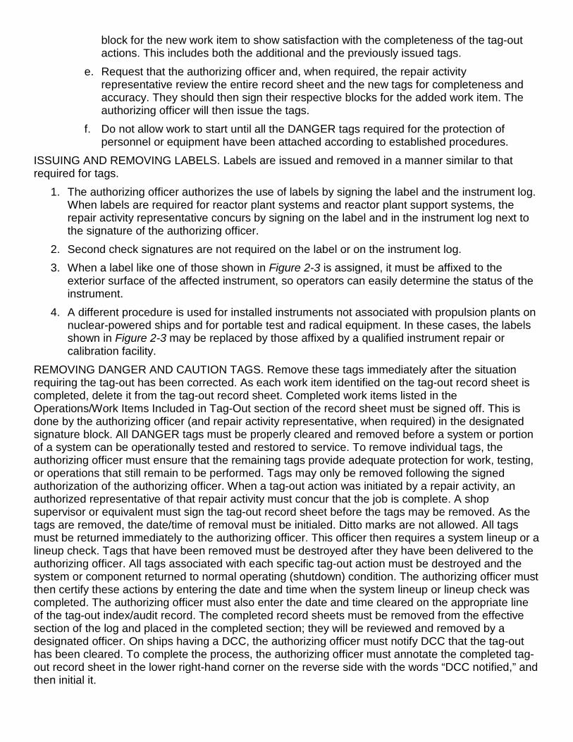
REMOVING DANGER AND CAUTION TAGS. Remove these tags immediately after the situation requiring the tag-out has been corrected. As each work item identified on the tag-out record sheet is completed, delete it from the tag-out record sheet. Completed work items listed in the Operations/Work Items Included in Tag-Out section of the record sheet must be signed off. This is done by the authorizing officer (and repair activity representative, when required) in the designated signature block. All DANGER tags must be properly cleared and removed before a system or portion of a system can be operationally tested and restored to service. To remove individual tags, the authorizing officer must ensure that the remaining tags provide adequate protection for work, testing, or operations that still remain to be performed. Tags may only be removed following the signed authorization of the authorizing officer. When a tag-out action was initiated by a repair activity, an authorized representative of that repair activity must concur that the job is complete. A shop supervisor or equivalent must sign the tag-out record sheet before the tags may be removed. As the tags are removed, the date/time of removal must be initialed. Ditto marks are not allowed. All tags must be returned immediately to the authorizing officer. This officer then requires a system lineup or a lineup check. Tags that have been removed must be destroyed after they have been delivered to the authorizing officer. All tags associated with each specific tag-out action must be destroyed and the system or component returned to normal operating (shutdown) condition. The authorizing officer must then certify these actions by entering the date and time when the system lineup or lineup check was completed. The authorizing officer must also enter the date and time cleared on the appropriate line of the tag-out index/audit record. The completed record sheets must be removed from the effective section of the log and placed in the completed section; they will be reviewed and removed by a designated officer. On ships having a DCC, the authorizing officer must notify DCC that the tag-out has been cleared. To complete the process, the authorizing officer must annotate the completed tag-out record sheet in the lower right-hand corner on the reverse side with the words “DCC notified,” and then initial it.
• When any component is tagged more than once, the DANGER tag takes precedence over all other tags. All DANGER tags must be removed and cleared before the equipment may be operationally tested or operated.
• A missing or damaged tag is reissued by indicating on the tag-out record sheet, on the line corresponding to the damaged or missing tag, that the tag was missing or damaged and that a replacement was issued. The new tag is issued using the next number in the tag-out record sheet. The authorizing officer should sign the tag-out record sheet to authorize the clearing of damaged or missing tags and to authorize their replacement.
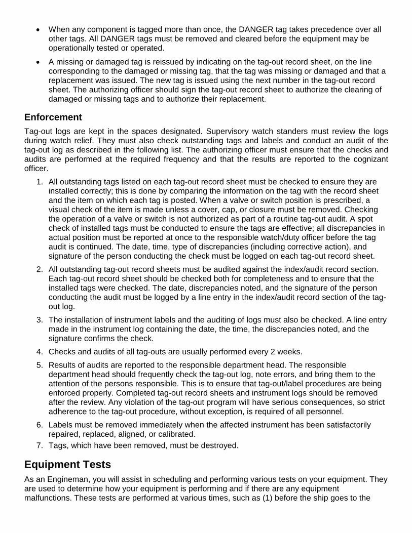
Enforcement Tag-out logs are kept in the spaces designated. Supervisory watch standers must review the logs during watch relief. They must also check outstanding tags and labels and conduct an audit of the tag-out log as described in the following list. The authorizing officer must ensure that the checks and audits are performed at the required frequency and that the results are reported to the cognizant officer.
1. All outstanding tags listed on each tag-out record sheet must be checked to ensure they are installed correctly; this is done by comparing the information on the tag with the record sheet and the item on which each tag is posted. When a valve or switch position is prescribed, a visual check of the item is made unless a cover, cap, or closure must be removed. Checking the operation of a valve or switch is not authorized as part of a routine tag-out audit. A spot check of installed tags must be conducted to ensure the tags are effective; all discrepancies in actual position must be reported at once to the responsible watch/duty officer before the tag audit is continued. The date, time, type of discrepancies (including corrective action), and signature of the person conducting the check must be logged on each tag-out record sheet.
2. All outstanding tag-out record sheets must be audited against the index/audit record section. Each tag-out record sheet should be checked both for completeness and to ensure that the installed tags were checked. The date, discrepancies noted, and the signature of the person conducting the audit must be logged by a line entry in the index/audit record section of the tag-out log.
3. The installation of instrument labels and the auditing of logs must also be checked. A line entry made in the instrument log containing the date, the time, the discrepancies noted, and the signature confirms the check.
4. Checks and audits of all tag-outs are usually performed every 2 weeks. 5. Results of audits are reported to the responsible department head. The responsible
department head should frequently check the tag-out log, note errors, and bring them to the attention of the persons responsible. This is to ensure that tag-out/label procedures are being enforced properly. Completed tag-out record sheets and instrument logs should be removed after the review. Any violation of the tag-out program will have serious consequences, so strict adherence to the tag-out procedure, without exception, is required of all personnel.
6. Labels must be removed immediately when the affected instrument has been satisfactorily repaired, replaced, aligned, or calibrated.
7. Tags, which have been removed, must be destroyed.
Equipment Tests As an Engineman, you will assist in scheduling and performing various tests on your equipment. They are used to determine how your equipment is performing and if there are any equipment malfunctions. These tests are performed at various times, such as (1) before the ship goes to the
shipyard for overhaul, (2) after post- deployment, (3) during a tender availability, or (4) as required by Planned Maintenance System (PMS). The tests are performed by the ship’s force, intermediate maintenance activity (IMA) personnel, shipyard personnel, or an inspection team (such as a Board of Inspection and Survey [INSURV]). Detailed types of inspections are described in COMNAVSURFLANT Maintenance Manual, COMNAVSURFLANTINST. 9000.1C or COMNAVSURFPAC Ship and Craft Maintenance Manual, Volumes 1 and 2, Planned Maintenance, COMNAVSURFPACINST. 4700.1B. two types of inspections and tests that can be used to “spot” impending trouble in an internal combustion engine are called trend and spectrographic analyses.
Engine Trend Analysis Preventive maintenance receives a great deal of attention from everyone in the field of diesel engine operation, since letting an engine run as long as it will run and fixing it only after a breakdown occurs is not only foolish, but extremely costly. You should know that vital parts of an engine last longer and operate better if they are not tampered with unnecessarily. One way to determine the condition of an engine is by monitoring its operation. This is done regularly obtaining certain engine operating data and by studying, analyzing, and comparing it with previous data. This information is then reduced to a form that all engineering personnel can interpret and decide whether the engine needs to be overhauled or just temporarily shut down for simple maintenance. For more detailed procedures, refer to NAVSEA S9233-C3-HBK-010 Rev 1, Diesel Engine, Over 400 BHP, and Trend Analysis Handbook.
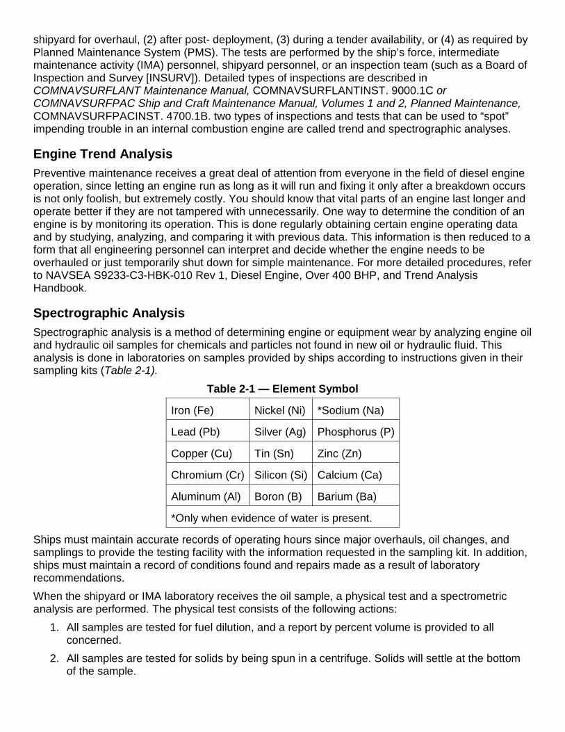
Spectrographic Analysis Spectrographic analysis is a method of determining engine or equipment wear by analyzing engine oil and hydraulic oil samples for chemicals and particles not found in new oil or hydraulic fluid. This analysis is done in laboratories on samples provided by ships according to instructions given in their sampling kits (Table 2-1).
Table 2-1 — Element Symbol
Iron (Fe) Nickel (Ni) *Sodium (Na)
Lead (Pb) Silver (Ag) Phosphorus (P)
Copper (Cu) Tin (Sn) Zinc (Zn)
Chromium (Cr) Silicon (Si) Calcium (Ca)
Aluminum (Al) Boron (B) Barium (Ba)
*Only when evidence of water is present.
Ships must maintain accurate records of operating hours since major overhauls, oil changes, and samplings to provide the testing facility with the information requested in the sampling kit. In addition, ships must maintain a record of conditions found and repairs made as a result of laboratory recommendations. When the shipyard or IMA laboratory receives the oil sample, a physical test and a spectrometric analysis are performed. The physical test consists of the following actions:
1. All samples are tested for fuel dilution, and a report by percent volume is provided to all concerned.
2. All samples are tested for solids by being spun in a centrifuge. Solids will settle at the bottom of the sample.
3. Allowable “use limits” are tested and recorded. When the physical test is completed, the shipyard/IMAs will make a spectrometric analysis of each used oil sample, then report to all concerned the concentrations of the elements listed in Table 2-1in parts per million (ppm).
Additional information on trend analysis and oil spectrometric analysis is contained in COMNAVSURFLANTINST 9000.1C or COMNAVSURFPACINST 4700.1B.
TRAINING The higher you progress as an Engineman; you will be responsible for passing your skills and knowledge on to other, lower-rated Engineman. Your level of experience and theoretical knowledge will be successful in training others. Success in training others requires that you have or develop certain additional skills as an instructor.
Training Responsibilities You must be technically competent before you can teach others, but your technical competence must be supplemented by the ability to organize information, to present it effectively, and to arouse and keep the interest of your trainees. You will find excellent general information on how to plan, carry out, and evaluate an instructional program in Military Requirements for Petty Officer Second Class, NAVEDTRA 12045, and in Military Requirements for Petty Officer First Class, NAVEDTRA 12046. Each person must be trained to perform not only as an individual but also as a member of a team. Take for instance the duties of the watch standers. They are very closely related, and the actions taken by one person depend in some way upon the actions taken by other persons. The teamwork required for engine-room operations can actually be turned to a training advantage. As a person is being trained for one specific duty, he or she will naturally learn something about the other duties. The procedures for training a new person in engine-room operations vary considerably, depending upon such factors as the ship’s steaming schedule, the condition of the engine-room machinery, the number of experienced personnel available to assist in the training, and the amount of time that can be devoted to the training. You will probably Begin by training the trainee to act as messenger. Then, before the trainee is assigned to any actual duty, he or she should be introduced to the engine room and become familiar with the location of all machinery, equipment, piping, and valves. The trainee must also be instructed in certain basic safety precautions and be specifically warned about the dangers of turning valve wheels or tampering with machinery. “IF IN DOUBT, ASK QUESTIONS!” is a good rule for any new person in the engine room to follow. A person ready to be trained in the duties of messenger should be shown all the gauges that are in use, told what the gauges indicate, and shown how to take readings. The trainee should understand why the readings are important, exactly how often each gauge must be read, and how to make accurate entries in the engine-room log. When you are sure the trainee understands everything about gauges, teach the trainee how to check lube oil levels and how to clean metal edge-type filters and basket strainer-type. For a while you will have to keep a close watch on the trainee’s performance of these duties. When the trainee becomes proficient in the duties of messenger, start the training in the throttleman’s duties. First, let the trainee observe the throttleman; then, if conditions permit, let the trainee start and secure machinery. Personnel should always start out under the supervision of an experienced throttleman and should remain under this supervision until the petty officer in charge of the engine room is fully satisfied that the trainee is completely qualified for this duty. In training engine-room personnel who have not had previous engine-room experience, remember that an engine room can be a complicated and confusing place to someone who walks into it for the first time. A lot of equipment is crammed into a small space, and a lot of complex actions are going on at the same time. When training new personnel, try to think back to the time when you first went into
an engine room. What aspects of engine-room operations were most confusing to you at first? What kind of training would have made your learning easier and faster? By analyzing your own early experience and reactions, you get a bearing on what a new person may experience and you may be able to provide more effective training. When you train new personnel, remember that they vary widely in their methods and rates of learning. Some people will learn most effectively if you give them an overall view of main engine operations, including a certain amount of theory, before going into the details of the hardware and the manual operations. Others will learn most effectively if they are taught some manual skills before getting too involved with theory. Some people learn manual skills rapidly but take a long time to absorb the theory; for others, the reverse is true. And, of course, some people learn everything slowly. Some trainees benefit from patient, almost endless repetition of information; others may become bored and restless if you go over the same point too often. The important thing to remember is that your training efforts will be most successful if you are able to observe and allow for the individual differences that are bound to exist. When training personnel who have already had some engine-room experience but who have been on some other type of ship, you may find that a certain amount of retraining is needed before the individual can qualify as an engine-room watch stander on your ship. No two engine rooms are precisely alike in all details, and no two main engines that appear to be identical behave in precisely the same way under all conditions. Each engine has its own individuality, and operating personnel must adjust to the engine to obtain the best results.
Safety Training Because of the necessity for strict observance of safety precautions, all engine-room operational training must be rigidly controlled and supervised. On-the-job training is necessary if an individual is to acquire the actual skills needed for main engine operation. Safety precautions should be taught from the very beginning and should be emphasized constantly throughout the training program. Many of the NSTMs, manufacturer’s technical manuals, and every PMS maintenance requirement card (MRC) include safety precautions. Additionally, Naval Occupational Safety and Health (NAVOSH) Program Manual for Forces Afloat OPNAVINST 5100.19B, and NAVOSH Program Manual, OPNAVINST 5100.23B, provide safety and occupational health information. The safety precautions are to protect you and the equipment During preventive and corrective maintenance, the procedures may call for personal protective equipment (PPE) such as goggles, gloves, hearing protection, and respirators. When specified, your use of PPE is mandatory. You must select PPE appropriate for the job since the equipment is manufactured and approved for different levels of protection. If the procedure does not specify the PPE, and you aren’t sure, ask your safety officer. Most machinery, spaces, and tools requiring you to wear hearing protection are posted with hazardous noise signs or labels. Eye hazardous areas requiring you to wear goggles or safety glasses are also posted. In areas where corrosive chemicals are mixed or used, an emergency eye wash station must be installed. All lubricating agents, oils, and cleaning materials are hazardous materials. Hazardous materials require careful handling, storage, and disposal. PMS documentation provides hazard warnings or refers the maintenance person to the Hazardous Materials User’s Guide (HMUG). Material Safety Data Sheets (MSDSs) also provide safety precautions for hazardous materials. All commands are required to have an MSDS for each hazardous material in their inventory. You must be familiar with the dangers associated with the hazardous materials you use in your work Additional information is available from your command’s hazardous material/hazardous waste coordinator. Workers must always consider electrical safety when working around any electrical or electronic machinery or equipment. Procedures normally include special precautions and tag-out requirements
for electrical safety. You should review your command’s electrical safety program instruction and procedures before beginning any work on electrical or electronic equipment or before working with portable electrical tools. In your work center or shop, there is equipment that will help you do your job easier and more quickly, requires special knowledge of safe operation and proper maintenance. As an Engineman you will be involved in providing training on how to use this equipment. All shop personnel, including you, must complete the Personnel Qualification Standard (PQS) for each piece of equipment before using it. You will assist your supervisor in providing the information and training. Normally in the shop or work center, every piece of equipment must have a posted operating procedure and a list of personnel who are qualified to use it. If a piece of equipment does not have posted operating procedures, post a copy of the procedures given in the manufacturer’s manual.
Training Programs As an Engineman, you are required to assist your supervisors in establishing or maintaining a training program for your work center. For this program you are required to teach the proper methods of equipment operation, repair, and safety. You should use all appropriate materials as teaching aids, such as manufacturer’s manuals, instructions, and NSTMs. For certain types of information, you may need to consult various kinds of engineering handbooks, such as the mechanical engineering handbooks, marine engineering handbooks, piping handbooks, and other handbooks that provide detailed, specialized technical data. In addition, you should know what schools are available. In recent years, one of the best ways to check on how well personnel retain the information being taught in the training program has been the use of the PQS. A PQS is a written list of knowledge and skills required to qualify for a specific watch station, maintain a specific piece of equipment or system, or perform as a team member within an assigned unit. Most standards are divided into four sections: Fundamentals, Systems, Watchstations, and a Qualification Card. The Fundamentals section contains the facts, principles, and fundamentals concerning the subject for which a person is qualifying. The Systems section deals with the major working parts of the installation, organization, or equipment with which the PQS is concerned. The Watchstation section defines the actual duties, assignments, and responsibilities needed for qualification. The Qualification Card has questions that match those in the Watchstation section and provides a space for the supervisor’s or the qualifying officer’s signature. In addition to qualifying under PQS, both you and your subordinates must satisfy Maintenance and Material Management (3-M) Systems and general damage control qualification requirements.
ENGINEERING OPERATIONAL SEQUENCING SYSTEM (EOSS) Each new ship that joins the Navy is more technically advanced and complex than the one before. The main propulsion plants call for engineering skills at ever higher levels of competence. That means more and better training of personnel who must keep the ships combat ready. The need for training and the problem of frequent turnover of trained personnel call for some kind of system that can be used to keep things going smoothly during the confusion. The Engineering Operational Sequencing System (EOSS) was developed for that purpose. It is designed to eliminate problems due to operator error during the alignment of piping systems and the starting and stopping of machinery. It involves the participation of all personnel from the department head to the fireman on watch. EOSS consists of a set of detailed written procedures, using charts, instructions, and diagrams. These aids are developed for safe operation and casualty control of a specific ship’s engineering plant and configuration. EOSS improves the operational readiness of the ship’s

engineering plant by providing positive control of the plant. This, in turn, reduces operational casualties and extends machinery life. EOSS is divided into two subsystems:
• Engineering Operational Procedures (EOPs)
• Engineering Operational Casualty Control (EOCC)
Engineering Operational Procedures (EOPs) EOPs are prepared specifically for each level of operation: plant supervision (level 1), space supervision (level 2), and component/system operator (level 3). The materials for each level or stage of operation contain only the information necessary at that level. All materials are interrelated. They must be used together to maintain the proper relationship and to ensure positive control and sequencing of operational events within the plant. Ships that do not have EOSS use operating instructions and a casualty control manual for plant operations.
Engineering Operational Casualty Control (EOCC) This subsystem of EOSS enables plant and space supervisors to RECOGNIZE the symptoms of a possible casualty. They can then CONTROL the casualty to prevent possible damage to machinery, and RESTORE plant operation to normal. The documents of the EOCC subsystem contain procedures and information that describe symptoms, causes, and actions to be taken in the most common engineering plant casualties.
Engineering Casualty Control The best form of casualty control is prevention. If you do not let a casualty happen, you will not have to fix it. Preventive maintenance is one of the principal factors of casualty control. Preventive inspections, tests, and maintenance are vital to casualty control. These actions minimize casualties caused by material failures. Continuous detailed inspections are necessary to discover worn or partly damaged parts, which may fail at a critical time. These inspections eliminate maladjustments, improper lubrication, corrosion, erosion, and other abnormalities that could cause early failure of a vital piece of machinery. The inspections, tests, and maintenance called for in the 3-M Systems must be performed conscientiously since they are based on the known requirements of preventive maintenance. Still, casualties do happen. When they do, the success of the mission, the safety of your ship, and the lives of your shipmates may depend on your ability to handle the situation. That means continuous training and frequent refresher drills to be sure you can do your part, and do it well. Engineering casualty control is used to prevent, minimize, and correct the effects of operational and battle casualties. These casualties will be on engineering space machinery, related machinery outside of engineering spaces, and the piping installations associated with the various pieces of machinery. The mission of engineering department personnel is to maintain all engineering services in a state of maximum reliability under all conditions. If you cannot provide these services, the ship may not be able to fight. Steps involved in handling engineering casualties can be divided into three general phases:
1. Immediate action to prevent further damage. 2. Supplementary action to stabilize the plant condition.
3. Restoration action to restore equipment to operation after a casualty. Where equipment damage has occurred, repairs may be necessary to restore machinery, plants, or systems to their original condition.
Communication of accurate information is one of the major problems in casualty control. Be sure you know the names and operations of the equipment at your normal watch station and your battle station. Be sure you know what the casualty is before you take corrective action. If you are reporting a casualty to the bridge or main control, be sure you use the correct terminology and ensure they understand what your casualty is. The primary sources of instructions used to handle any engineering casualty and to maintain the overall damage resistance to your ship are listed as follows:
• The EOCC procedure
• The ship’s casualty control manual (for a ship without EOCC)
• The ship’s damage control manual
• The ship’s damage control bills
• The ship’s organization and regulation manual (SORM)
Symptoms of Operational Casualties You must be on the alert for even the most minor sign of faulty operation of machinery. Pay particular and continuous attention to the following symptoms of malfunctioning:
• Unusual noises
• Vibrations
• Abnormal temperatures
• Abnormal pressures
• Abnormal operating speeds
• Leakage from systems or associated equipment You should become thoroughly familiar with the normal operating temperatures, pressures, and speeds of equipment specified for each condition of operation; departures from normal will then be readily apparent. NEVER assume that an abnormal reading on a gauge or other indicating instrument is due to a problem with the instrument. Investigate each case to learn the cause of the abnormal reading. Substitute a spare instrument or perform a calibration test to quickly show whether an instrument error exists. Trace abnormal readings that are not caused by faulty instruments to their source. Some specific advance warnings of failure are outlined in the following paragraphs. The safety factor commonly incorporated in pumps and similar equipment can allow a considerable loss of capacity before you see any external evidence of trouble. In pressure-governor-controlled equipment, view changes in operating speeds from normal for the existing load with suspicion. Variations from normal in chest pressures, lubricating oil temperatures, and system pressures indicate either improper operation or poor condition of the machinery. When a material failure occurs in any unit, promptly inspect all similar units to determine whether they are subject to the same type of failure. Prompt inspection may eliminate a wave of similar casualties. Abnormal wear, fatigue, erosion, or corrosion of a part may indicate that the equipment is not being operated within its designed limits of loading, speed, and lubrication. These symptoms also may indicate a design or material deficiency. If any of these symptoms have appeared, you should routinely carry out special inspections to detect damage unless you can take action to ensure that such a condition will not recur.
Engine-Room Casualties Even with the best-trained personnel and the best-planned maintenance programs, casualties will occur. WHEN COMBATING AN ENGINE-ROOM CASUALTY, USE YOUR EOCC.
Diesel Engine Casualties The Engineman’s duties concerning engineering casualties and their control depend upon the type of ship, which may be anything from a torpedo weapons retriever (TWR) to a carrier. An Engineman operates engines of various sizes, made by various manufacturers, and intended for different types of services. Some examples of the types of engineering casualties that may occur and the action to be taken are given in the sections that follow. The observance of all necessary safety precautions is essential in all casualty control procedures.
1. Inoperative speed governor. a. Control the engine manually, if possible. b. Notify the engineer officer and the bridge, and request permission to secure the engine
for repairs. c. When you get permission, check the governor control mechanism. d. Check the linkage for binding or sticking. e. Check the lubrication; flush the governor sump and refill it with proper oil. f. Check the setting of the needle valve. g. Make repairs. When you have completed the repairs, start the engine and check its
operation. When it is operating properly, notify the engineer officer and the bridge. 2. Engine cooling water temperature above the allowed limit.
a. Notify the bridge. b. Reduce the load and the speed of the engine. c. Check the freshwater level in the expansion tank. d. Check the saltwater discharge pressure. e. Check the sea suction and the discharge valves. f. Vent the freshwater and the saltwater pumps. g. Check the setting and operation of the temperature regulating valve.
3. Failed main engine lube oil pressure. a. Secure the engine immediately. b. Notify the engineer officer and the bridge. c. Check the sump oil level, the piping, the filters, the strainers, and the lube oil pump
capacity. Make the repairs. d. After you have completed the repairs, notify the engineer officer and the bridge.
For more generalized examples of main engine (diesel-drive) casualties, refer to Damage Control, Engineering Casualty Control, Chapter 079, Volume 3, of NSTM. To obtain detailed information on diesel engine casualty control procedures, refer to the manufacturer’s instructions, the pertinent TYCOM’s instructions, and the ship’s Engineering Casualty Control Manual.
Watch Standing You will spend much of your time aboard ship as a watch stander. How you stand your watch is very important to the reliability of the engineering plant and the entire ship. To be a successful watch stander, you must do the following:
• Have the skills to detect unusual noises, vibrations, or odors that may indicate faulty machinery operation.
• Take appropriate and prompt corrective measures.
• Be ready, in emergencies, to act quickly and independently.
• Know the ship’s piping systems and HOW, WHERE, and WHY they are controlled.
• Know each piece of machinery: how it is constructed, how it operates, how it fits into the engineering plant, and where related equipment is controlled.
• Be able to read and interpret measuring instruments.
• Understand how and why protective devices function (relief valves, speed limiting governors, overspeed trips, and cut-in and cutout devices).
• Recognize and remove fire hazards, stow gear that is adrift, and keep deck plates clean and dry.
• NEVER try to operate a piece of equipment that is defective.
• Report all unsafe conditions to the space or plant supervisor.
• Know the status of every piece of machinery at your station.
• Promptly handle any necessary change in speed or setup, and record correctly all data concerning the operation and maintenance of the machinery.
• Be sure the log is up to date and the status boards are current.
• Know what machinery is operating and what the night orders and standing orders are before you relieve the watch.
Above all, if you don’t know, ASK! A noise, odor, or condition may seem abnormal to you, but you may not be certain whether it is a problem. When that happens, call your immediate watch supervisor. You can best gain the respect and confidence of your supervisors and shipmates if you stand a good watch. Relieve the watch on time or even a little early if possible to be sure you know the condition of the machinery and what you need to do. DO NOT TRY TO RELIEVE THE WATCH FIRST AND FIGURE OUT THE SITUATION LATER. The same applies when you are being relieved; don’t be in a hurry to take off. Be sure your relief understands the situation completely. Before you are relieved, make sure your station is clean and squared away. These little considerations will strengthen your reputation and improve the overall quality of watch standing within the department.
QUALITY ASSURANCE PROGRAM The quality assurance (QA) program was established to provide personnel with information and guidance necessary to administer a uniform policy of maintenance and repair of ships and submarines. The QA program is intended to introduce discipline into the repair of equipment, safety of personnel, and configuration control, thereby enhancing readiness. The various QA manuals set forth minimum QA requirements for both the surface fleet and the submarine force. If more stringent requirements are imposed by higher authority, such requirements
take precedence. If a conflict exists between the QA manual and previously issued letters and transmittals by the appropriate force commanders, the QA manual takes precedence. The instructions contained in the QA manual apply to every ship and activity of the force. Although the requirements are primarily applicable to the repair and maintenance done by the force IMAs, they also apply to maintenance done aboard ship by ship’s force. In all cases where specifications cannot be met, a departure-from-specifications request must be completed and reported. Because of the wide range of ship types and equipment and the varied resources available for maintenance and repair, the instructions set forth in the QA manual are necessarily general in nature. Each activity must implement its own QA program to meet the intent of the QA manual. The goal should be to have all repairs conform to QA specifications.
Program Components The basic thrust of the QA program is to make sure you comply with technical specifications during all work on ships of both the surface fleet and submarine force. The key elements of the program are as follows:
• Administrative. This includes training and qualifying personnel, monitoring and auditing programs, and completing the QA forms and records.
• Job execution. This includes preparing work procedures, meeting controlled material requirements, requisitioning material, conducting in-process control of fabrication and repairs, testing and recertifying, and documenting any departure from specifications.
A properly functioning QA program points out problem areas to maintenance managers so they can take appropriate action in a timely manner. The following goals are common to all Navy QA programs:
1. To improve the quality, uniformity, and reliability of the total maintenance effort. 2. To improve work environment, tools, and equipment used in the performance of maintenance. 3. To eliminate unnecessary man-hour and dollar expenses. 4. To improve the training, work habits, and procedures of all maintenance personnel. 5. To increase the excellence and value of reports and correspondence originated by the
maintenance activity. 6. To distribute required technical information more effectively. 7. To establish realistic material and equipment requirements in support of the maintenance
effort.
Quality Assurance Organization The QA program for naval forces is organized into different levels of responsibility. For example, the COMNAVSURFPAC QA program is organized into the following levels of responsibility: TYCOM, readiness support group/area maintenance coordinator, and the IMAs. The QA program for the Naval Surface Force for the Atlantic Fleet is organized into five levels of responsibility: force commander, audits, squadron commanders, IMAs, and force ships. The QA program organization (Navy) begins with the commander in chief of the fleets, which provides the basic QA program organization responsibilities and guidelines. The TYCOMs provide instruction, policy, and overall direction for implementation and operation of the force QA program. TYCOMs have a force QA officer assigned to administer the force QA program.
The COs are responsible to the force commander for QA in the maintenance and repair of the ships. The CO is responsible for organizing and implementing a program within the ship to carry out the provisions of the TYCOM QA manual. The CO ensures that all repair actions performed by ship’s force conform to provisions of the QA manual as well as other pertinent technical requirements. The Quality Assurance Officer (QAO) is responsible to the CO for the organization, administration, and execution of the ship’s QA program according to the QA manual. The QAO is responsible for coordinating the ship’s QA training program, for maintaining ship’s QA records, and for test and inspection reports. The QAO conducts QA audits as required and follows up on corrective actions to ensure compliance with the QA program. The ship quality control inspectors (SQCIs), usually the work center supervisor and two others from the work center, must have a thorough understanding of the QA program. Some of the other responsibilities an SQCI will have are as follows:
1. Inspect all work for compliance with specifications. 2. Maintain ship records to support the QA program. 3. Ensure that only calibrated equipment is used in acceptance testing and inspection of work. 4. Witness and document all tests. 5. Ensure that all materials or test results that fail to meet specifications are recorded and
reported.
Ship-to-Shop Work Many repair jobs are designated by the ship or approved by the repair activity as “ship-to-shop” jobs. For example, the repair or renewal of a damaged pump shaft might well be written up as a ship-to-shop job. The ship’s force will disassemble the pump and remove the shaft. Then the shaft and any necessary blueprints or technical manuals are delivered to the designated shop of the repair activity. After the shaft has been repaired, or a new one has been made, it is picked up and brought back to the ship by the ship’s force. The pump is reassembled, inspected, and tested by the ship’s force to make sure it is operating satisfactorily. The important thing to remember is that the repair facility is responsible for ensuring that its personnel repair or manufacture this to the manufacturer’s specifications, perform all tests required by QA, and properly fill out all the required forms. You are responsible for witnessing any test required by QA, monitoring the status of the job at all times, and reassembling and test operating the pump properly. The end results will produce a reliable, operating piece of equipment.
Levels of Essentiality A level of essentiality is a range of controls, in two broad categories, representing a certain high degree of confidence that procurement specifications have been met. These categories are:
• Verification of material
• Confirmation of satisfactory completion of tests and inspections required by the ordering data Levels of essentiality are codes, assigned by the ship according to the QA manual, that indicate the degree to which the ship’s system, subsystem, or components are necessary in the performance of the ship’s mission. These codes indicate the impact that catastrophic failure of the associated part or equipment would have on the ship’s mission capability and personnel safety.
Levels of Assurance QA is divided into three levels: A, B, and C. Each level reflects certain quality verification requirements of individual fabrication in process or repair items. Level A assurance provides for the most stringent of restrictive verification techniques. This level requires both quality controls and test or inspection methods. Level B assurance provides for adequate verification techniques, requires limited quality controls, and may or may not require tests or inspections. Level C assurance provides for minimum or “as necessary” verification techniques and requires very little quality control of tests or inspections. The QA concept involves preventing the occurrence of defects. QA covers all events from the start of a maintenance action to its completion and is the responsibility of all maintenance personnel. By carefully following the methods and procedures outlined in your QA program manuals and by paying careful attention to the quality of work in your area, you will contribute greatly to the operational effectiveness of your ship as well as tended units.
SUMMARY In this chapter, we have discussed some of your important administrative and training responsibilities and the different methods you can use to properly perform these responsibilities. Remember, information is usually available when you need it. You just have to know where to look for it and make the effort to secure it.
End of Chapter 2
Basic Administration and Training
Review Questions 2-1. Which of following engineering department’s records must be preserved as permanent legal
records?
A. Engineering Log/Fuel and Water Report B. Engineering Bell Log/Monthly Summary C. Engineering Log/Engineering Bell Book D. Machinery History/Boiler Room Operating Record
2-2. What is the standard engine order telegraph symbol for back emergency speed?
A. Z B. 1 C. BF D. BEM
2-3. Which of the following documents indicates the amount of fuel on hand as of midnight, the
previous day?
A. Daily Boat Fueling Report B. Fuel and Water Account C. Fuel and Water Report D. Diesel Engine Operating Record
2-4. Information about engineering records that must be kept permanently, is contained in which of
the following publications?
A. NSTM Chapter 080 B. SECNAVINST P5212.5(series) C. NAVSHIPS 5084 D. NAVSHIPS 3648
2-5. When a piece of equipment fails, you must take which of the following actions before repairs
can begin?
A. Isolate and tag-out the system/equipment B. Notify the Type Commander C. Submit an OPNAV Form 4790K D. Request permission the relieve pressure from the system before isolation
2-6. When repairs have been completed on a piece of equipment, what must be accomplished
before the operational testing of equipment or system?
A. Complete the work request B. Warm up the system C. Align the equipment/system in accordance with EOP D. Clear the tags
2-7. What documents are used as a precautionary measure, providing special instructions and warning of unusual measures that must be used to operate the tagged item?
A. DANGER TAGS B. CAUTIONS TAGS C. OUT-OF-CALIBRATION LABELS D. OUT-OF-COMMISSION LABELS
2-8. What documents are used to identify instruments that will not give accurate readings because
they are either defective or isolated from the system?
A. Danger Tags B. Caution Tags C. Out-of-Calibration Labels D. Out-of-Commission Labels
2-9. What method is used to determine if an engine needs to be overhauled or just temporarily shut
down for sample maintenance?
A. The current engine operating data is compared with the previous operating data. B. The operating data of the engine is compared with same type. C. The temperature of the lube oil entering the cooler is compared to that leaving the
cooler. D. The present amount of lube oil consumption is compared with the previous lube oil
consumption. 2-10. If your ship is home-ported on the West Coast and you need additional information concerning
trend analysis and oil spectrometric analysis, to what Navy instruction should you refer?
A. OPNAVINST 43P1 B. COMNAVSURFLANTINST 9000.1C C. COMNAVSURFPACINST 4700.1B D. SECNAVINST P5212.5
2-11. Where would you be able to find the most information about Engine Trend Analysis?
A. NAVSEA S9233-C3-HB-010.010 B. COMNAVSURFLANTINST 9000.1C C. COMNAVSURFPACINST 4700.1B D. SECNAVINST P5212.5
2-12. Which of the following factors does NOT help in determining the procedures for training a new
person in engine-room operations
A. Ship’s operating schedule B. Number of experienced personnel available C. Condition of engine-room equipment D. Trainee’s manual skills level
2-13. What factors should be emphasized constantly throughout an engine-room training program?
A. Safety precautions B. Trial and error techniques C. Emergency repairs procedures D. Machinery characteristics
2-14. What section of the PQS deals with the major working parts of the installation, organization, or
equipment?
A. Fundamentals B. Systems C. Watchstations D. Qualification Cards
2-15. What is required of all commands to have on hand for every piece of hazardous material in
their inventory?
A. Material Safety Data Sheet B. Material Safety Document Sheet C. Material Safety Data List D. Maintenance Safety Data Sheets
2-16. Which of the following is contained in the Engineering Operational Casualty Control (EOCC)
subsystem?
A. Watch qualification B. Casualty symptoms C. Casualty reporting to the Type Commander D. Casualty reports to Fleet Commander
2-17. When combatting an engine-room casualty, which of the following items would you use?
A. EOP B. NSTM C. EOCC D. The Watch, Quarter, and Station Bill
2-18. In the Engineering Operational Procedures (EOPs), what level of operation is for the system
operators?
A. 1 B. 2 C. 3 D. 4
2-19. If a major piece of equipment has any material failure, which of the following pieces of information is essential to the Engineering Officer?
A. If there is similar failure in other pieces of equipment B. If it would be beneficial to exchange parts C. If there is a spare keep it operational D. If there are sufficient funds in the budget to cover the cost of repairs
2-20. To be a successful watch stander, you must be able do all of the following, EXCEPT……..
A. Operate equipment that you are qualified to operate. B. Be able to read and interpret measuring instruments. C. Recognize and remove hazards, stow gear that is adrift, and keep deck plates clean
and dry. D. Operate a pneumatic tool.
2-21. To get the best watch turnover information, when should you relieve the watch?
A. Right on time B. 15 minutes late C. A little early D. Whenever you decide to take the watch
2-22. Which of the following duties is NOT the responsibility of the Quality Assurance Officer?
A. Coordinating the ship’s QA training program B. Maintaining the ship’s record of test and inspection reports C. Conducting QA audits as required D. Monitoring work procedure for QA
2-23. Level B assurance provides which of the following levels of assurance?
A. Minimum verification B. Limited verification C. The most stringent verification D. Adequate verification
2-24. In regards to Ship-to-Shop work, who is responsible for witnessing any test requirements?
A. The ship’s QA personnel assigned to the Deck Department B. The work center representative who requested the work to be completed C. The repair facility supervisor D. The repair facility QA representative
RATE TRAINING MANUAL – User Update SWOS makes every effort to keep their manuals up-to-date and free of technical errors. We appreciate your help in this process. If you have an idea for improving this manual, or if you find an error, a typographical mistake, or an inaccuracy in SWOS manuals, please write or e-mail us, using this form or a photocopy. Be sure to include the exact chapter number, topic, detailed description, and correction, if applicable. Your input will be brought to the attention of the Technical Review Committee. Thank you for your assistance. Write: SWOS Project Manager
1534 Piersey Street Suite 321 Norfolk, VA 23511-2613 COMM: (757) 444-5332 DSN: 564-5332
E-mail: Refer to the Engineman Rating page under SWOS on the NKO Web page for current contact information.
Rate____ Course Name_____________________________________________
Revision Date__________ Chapter Number____ Page Number(s)____________
Description
_______________________________________________________________
_______________________________________________________________
_______________________________________________________________
(Optional) Correction
_______________________________________________________________
_______________________________________________________________
_______________________________________________________________
(Optional) Your Name and Address
_______________________________________________________________
_______________________________________________________________
_______________________________________________________________