Embed Size (px)
Citation preview
21
CHAPTER 2
AGENT BASED FUZZY LOGIC ROBOT NAVIGATION
AND OPTIMAL PATH PLANNING
2.1 INTRODUCTION
A pertinent problem in autonomous navigation is the need to cope
with the large amount of uncertainty that is inherent of natural environments
and responds reactively to unforeseen events as soon as they are perceived.
Moreover, uncertainty can occur in sensory data caused by environmental
features, and errors in the measurement interpretation process. Fuzzy logic
has features that make it an adequate tool to address this problem.
Applications in mobile robot navigation have been adopting fuzzy logic
approaches over the last two decades. However, this approach tries to prove
that it is enough just for the areas of highest danger coefficients to cause the
robot to change direction, which consequently reduces the number of fuzzy
rules that control the robot motion. The efficiency of the system is improved
by reducing the distance travelled by the robot to reach its goal position. The
proposed navigator consists of a Fuzzy-Based Collision Avoidance, pit
detection sensor and color sensor. The effectiveness of the proposed method
is verified by a series of simulations and real time implementation using
microcontroller in unknown environment.
Some important characteristics of fuzzy logic are as outlined by
Zadeh (1965).
22
Exact reasoning is viewed as a limiting case of approximate
reasoning.
Everything is a matter of degree.
Knowledge is interpreted as a collection of elastic, fuzzy
constraints on a collection of variables.
Inference is viewed as a process of propagation of elastic
constraints.
Any logical system can be “fuzzified.”
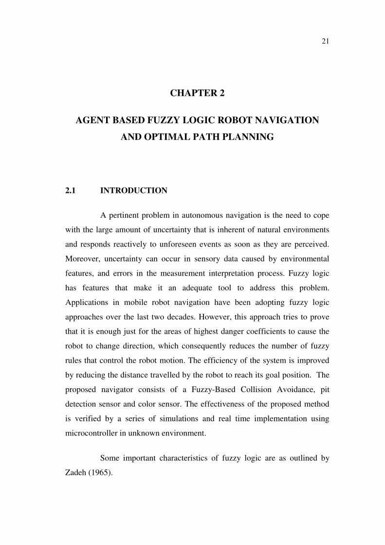
2.2 FUZZY SETS AND MEMBERSHIP FUNCTIONS
It should be reiterated that membership functions are subjective
measures for linguistic terms and are not probability functions. There are
many types of membership functions. Some of the more common ones
are triangular MFs, trapezoidal MFs, Gaussian MFs, and generalized bell
MFs. The figure below shows the definitions and graphs of these MFs
(Figure.2.1)
Figure 2.1 Types of Membership Functions
23
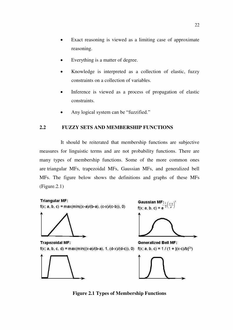
2.3 DEFUZZIFICATION
Defuzzification is the process of producing a quantifiable result in
fuzzy logic, given fuzzy sets and corresponding membership degrees. It is
typically needed in fuzzy control systems. These will have a number of rules
that transform a number of variables into a fuzzy result, that is, the result is
described in terms of membership in fuzzy sets.
A common and useful defuzzification technique is center of
gravity. First, the results of the rules must be added together in some way.
The most typical fuzzy set membership function has the graph of a triangle.
Now, if this triangle were to be cut in a straight horizontal line somewhere
between the top and the bottom, and the top portion were to be removed, the
remaining portion forms a trapezoid. The first step of defuzzification typically
"chops off" parts of the graphs to form trapezoids (or other shapes if the initial
shapes were not triangles). In the most common technique, all of these
trapezoids are then superimposed one upon another, forming a single
geometric shape. Then, the centroid of this shape, called the fuzzy centroid.
The x coordinate of the centroid is the defuzzified value. Formed by weighing
each functions in the output by its respective maximum membership value
(Figure 2.2)
Figure 2.2 Defuzzification
24
*
( ).
( )
C
C
z z
zz
* (.5) (.9)
.5 .9
a bz
2.4 PROPOSED SYSTEM
The proposed system has adopted methods such as following white
or magnetic lines using adequate sensors, and others. However, if the purpose
is to build robots with robust control that can be in any area of application
without having to engineer the area itself, the robot should be armed with
more intelligence, and should have its autonomy increased. Fuzzy logic has
features that make it an adequate tool to address this problem.
This approach divides the space into three categories range wise
and into six categories direction wise. However, this approach proved that it is
enough just for the areas of highest danger coefficients to cause the robot to
change direction, which consequently reduces the number of fuzzy rules that
control the robot motion. In the end, an optimization technique is applied for
the purpose of improving the system performance, where efficiency is
improved by reducing the distance traveled by the robot to reach its target. In
this system the robot will navigate in an unknown environment using fuzzy
logic. Sensors have been used to detect both the static and dynamic obstacles,
pits and the colors. The range depends on the type of sensors. Use of multi
agent approach and multi-agent optimal path planning make the system more
efficient in unknown environment.
2.4.1 System Structure
Figure 2.3 shows the integration of a microcontroller (89C52) with
the features of the robot. This architecture uses totally 5 sensors out of which
three proximity sensors are used to detect the obstacles, one to detect the color
and the other one to detect the pit in the navigation path. Two stepper motors
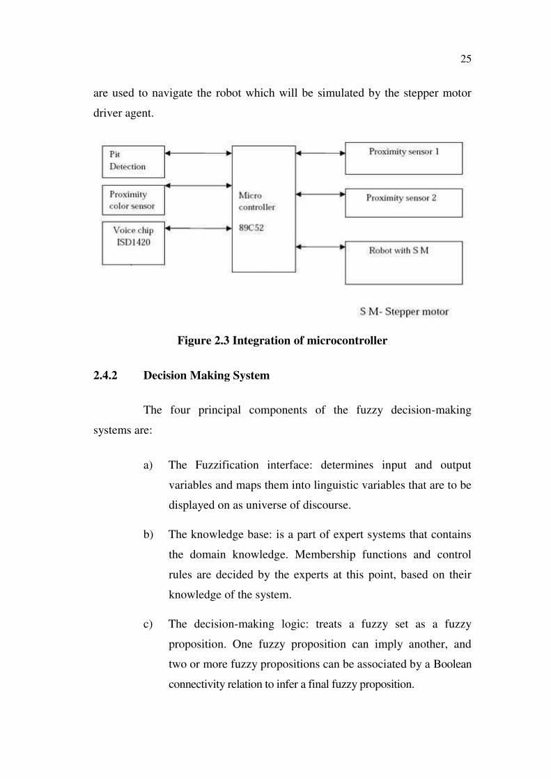
25
are used to navigate the robot which will be simulated by the stepper motor
driver agent.
Figure 2.3 Integration of microcontroller
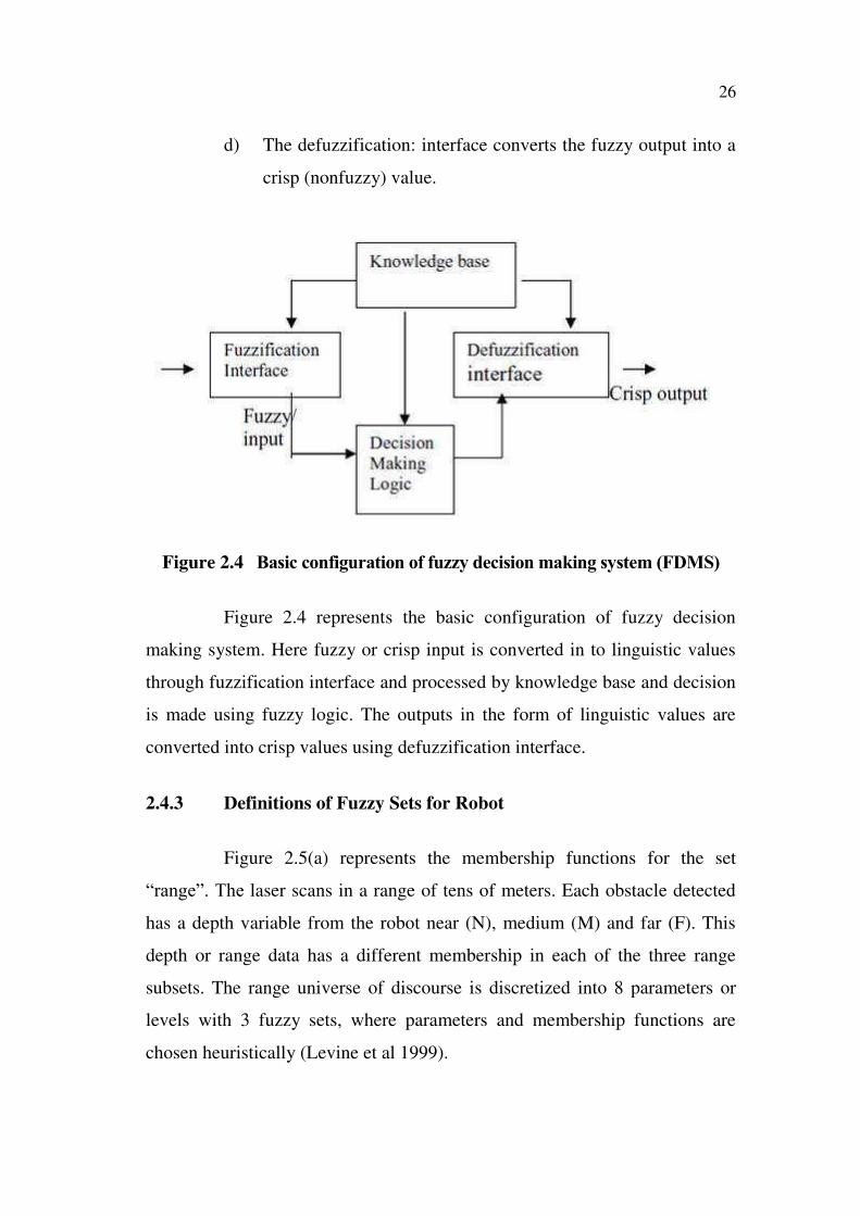
2.4.2 Decision Making System
The four principal components of the fuzzy decision-making
systems are:
a) The Fuzzification interface: determines input and output
variables and maps them into linguistic variables that are to be
displayed on as universe of discourse.
b) The knowledge base: is a part of expert systems that contains
the domain knowledge. Membership functions and control
rules are decided by the experts at this point, based on their
knowledge of the system.
c) The decision-making logic: treats a fuzzy set as a fuzzy
proposition. One fuzzy proposition can imply another, and
two or more fuzzy propositions can be associated by a Boolean
connectivity relation to infer a final fuzzy proposition.
26
d) The defuzzification: interface converts the fuzzy output into a
crisp (nonfuzzy) value.
Figure 2.4 Basic configuration of fuzzy decision making system (FDMS)
Figure 2.4 represents the basic configuration of fuzzy decision
making system. Here fuzzy or crisp input is converted in to linguistic values
through fuzzification interface and processed by knowledge base and decision
is made using fuzzy logic. The outputs in the form of linguistic values are
converted into crisp values using defuzzification interface.
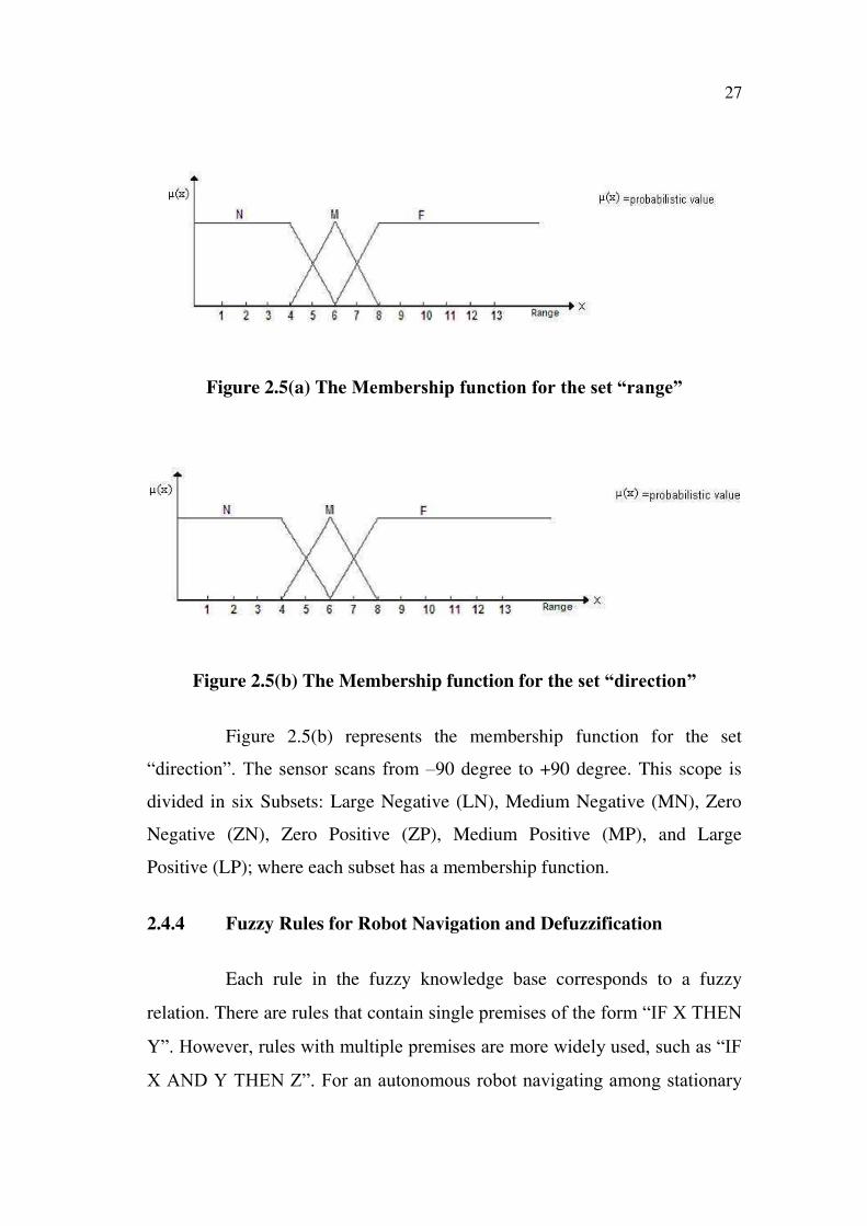
2.4.3 Definitions of Fuzzy Sets for Robot
Figure 2.5(a) represents the membership functions for the set
“range”. The laser scans in a range of tens of meters. Each obstacle detected
has a depth variable from the robot near (N), medium (M) and far (F). This
depth or range data has a different membership in each of the three range
subsets. The range universe of discourse is discretized into 8 parameters or
levels with 3 fuzzy sets, where parameters and membership functions are
chosen heuristically (Levine et al 1999).
27
Figure 2.5(a) The Membership function for the set “range”
Figure 2.5(b) The Membership function for the set “direction”
Figure 2.5(b) represents the membership function for the set
“direction”. The sensor scans from –90 degree to +90 degree. This scope is
divided in six Subsets: Large Negative (LN), Medium Negative (MN), Zero
Negative (ZN), Zero Positive (ZP), Medium Positive (MP), and Large
Positive (LP); where each subset has a membership function.
2.4.4 Fuzzy Rules for Robot Navigation and Defuzzification
Each rule in the fuzzy knowledge base corresponds to a fuzzy
relation. There are rules that contain single premises of the form “IF X THEN
Y”. However, rules with multiple premises are more widely used, such as “IF
X AND Y THEN Z”. For an autonomous robot navigating among stationary
28
obstacle in an unknown environment, it would be computationally expensive
to produce 3*6=18 rules as well as inefficient to divert the robot from its
trajectory for each fired rule. Hence, this thesis considers the zones of highest
risk which happen to be combinations of Near and Zero Negative as follows
(Shou-tao Li and Yuan-chun Li 2006):
1. If the range is near and angle is Zero Positive, then distance is
Medium and angle of deviation is Zero Negative
2. If range is near and angle is Zero Negative, then distance is
Medium and angle of deviation is Zero Positive.
3. If range is Medium and angle is Zero Positive, then distance is
near and angle of deviation is Zero Negative.
4. If range is Medium and angle is Zero Negative, then distance
is near and angle of deviation is Zero Positive.
The laser range finder upon detecting an obstacle, returns range and
orientation information to the fuzzy logic. A “Get Membership” routine is
applied iteratively to get different range and direction memberships. The
specified fuzzy rules are applied afterwards. In a crisp system, the intersection
of two sets contains the element that is common to both sets. This is
equivalent to the common logical AND operation. In conventional fuzzy
logic, the AND operator is supported by taking the minimum of the truth
membership grades. Range Outputs and Deviation Outputs from all the fired
rules are respectively multiplied in a Maximum relation so that final outputs
are converted back into crisp values. Here the technique inductive reasoning
is used for defuzzification (Miller 1998).
29
2.5 IMPLEMENTATION DETAILS
This system consists of two layers which constitute four task-
oriented agents. Each agent is composed of two functional layers, the
Hardware Layer and the Component Layer. The Hardware Layer is a
collection of modules communicating with the robot's hardware devices such
as the camera, infrared sensors and motors. One module can be shared by two
or more agents, which reduces redundancy in coding. The development tools
used is C language and Keil software, which is a part of Microsoft turbo C
and 89C52 IC. We have used 89C52 microcontroller as a controller circuit in
which the proximity sensors, stepper motor driver and the voice chip driver
were connected. Vector field histogram (VFH) algorithm is used for path
planning.
2.5.1 Multi Agent Systems
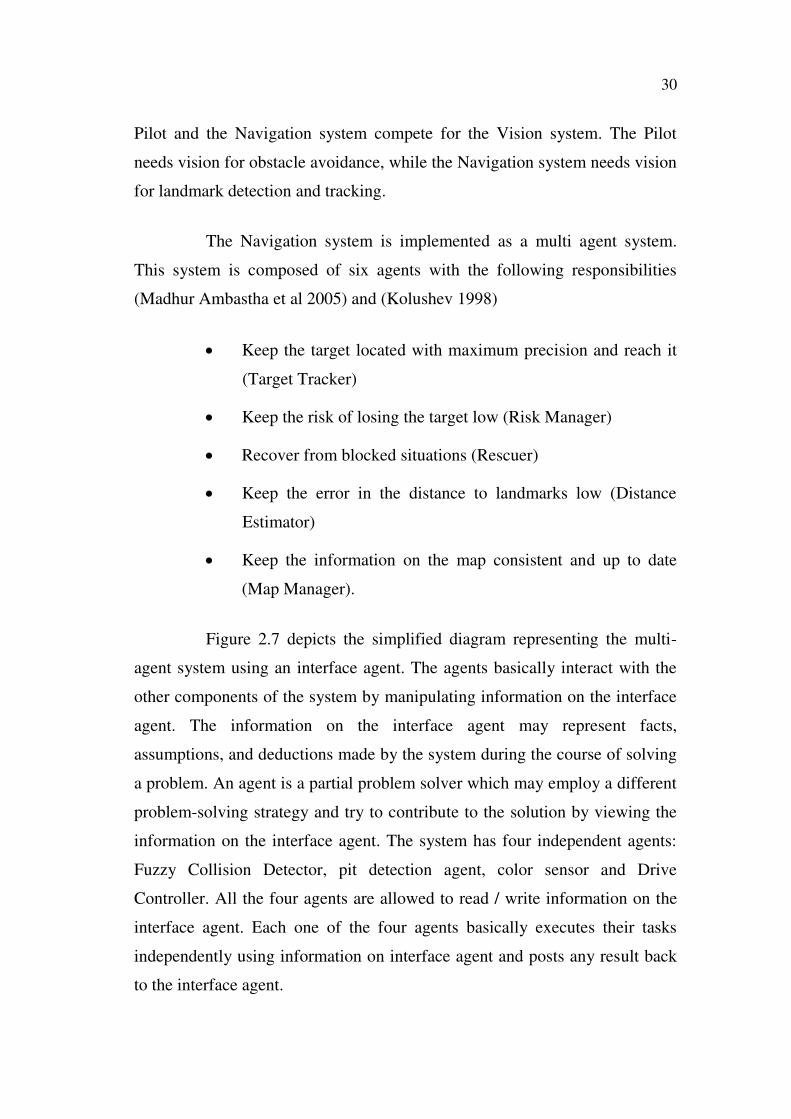
The architecture is composed of three systems (Figure 2.6). Each
system competes for two available resources: motion and vision. The Pilot is
responsible for all the motions of the robot. It selects these motions to carry
out commands from the Navigation system and to avoid obstacles. The Vision
system is responsible for identifying and tracking landmarks (including the
goal). Finally, the Navigation system is responsible for choosing higher level
robot motions to move the robot to a specified goal. This requires requesting
the Vision system to identify and track landmarks and to build a map of the
environment and requesting the Pilot to move the robot toward the goal
position or toward some intermediate target position. From this two
observations were made. First, these three systems must cooperate mutually to
achieve the overall task of reaching the goal landmark position. For instance,
the Pilot needs the Vision system to identify obstacles and it needs the
Navigation system to select a path to the goal. Second, the systems are also
competing - there are some trade-offs between them. For example, both the
30
Pilot and the Navigation system compete for the Vision system. The Pilot
needs vision for obstacle avoidance, while the Navigation system needs vision
for landmark detection and tracking.
The Navigation system is implemented as a multi agent system.
This system is composed of six agents with the following responsibilities
(Madhur Ambastha et al 2005) and (Kolushev 1998)
Keep the target located with maximum precision and reach it
(Target Tracker)
Keep the risk of losing the target low (Risk Manager)
Recover from blocked situations (Rescuer)
Keep the error in the distance to landmarks low (Distance
Estimator)
Keep the information on the map consistent and up to date
(Map Manager).
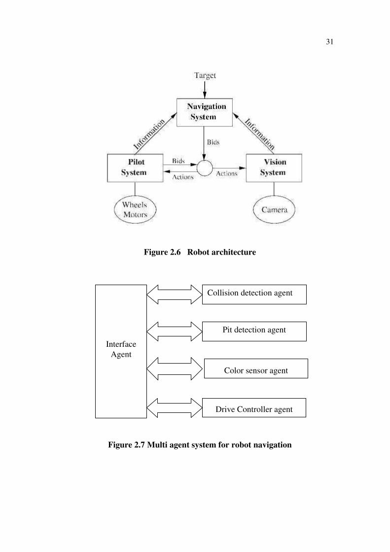
Figure 2.7 depicts the simplified diagram representing the multi-
agent system using an interface agent. The agents basically interact with the
other components of the system by manipulating information on the interface
agent. The information on the interface agent may represent facts,
assumptions, and deductions made by the system during the course of solving
a problem. An agent is a partial problem solver which may employ a different
problem-solving strategy and try to contribute to the solution by viewing the
information on the interface agent. The system has four independent agents:
Fuzzy Collision Detector, pit detection agent, color sensor and Drive
Controller. All the four agents are allowed to read / write information on the
interface agent. Each one of the four agents basically executes their tasks
independently using information on interface agent and posts any result back
to the interface agent.
31
Figure 2.6 Robot architecture
Figure 2.7 Multi agent system for robot navigation
Interface
Agent
Collision detection agent
Pit detection agent
Color sensor agent
Drive Controller agent
32
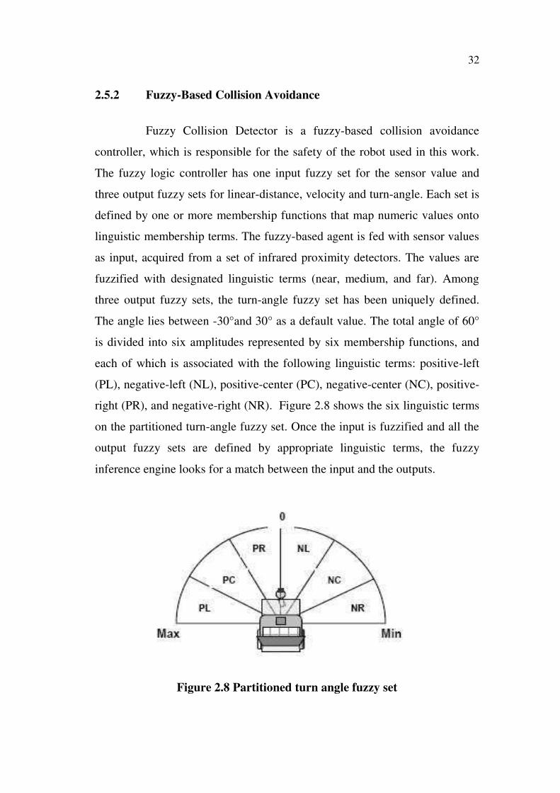
2.5.2 Fuzzy-Based Collision Avoidance
Fuzzy Collision Detector is a fuzzy-based collision avoidance
controller, which is responsible for the safety of the robot used in this work.
The fuzzy logic controller has one input fuzzy set for the sensor value and
three output fuzzy sets for linear-distance, velocity and turn-angle. Each set is
defined by one or more membership functions that map numeric values onto
linguistic membership terms. The fuzzy-based agent is fed with sensor values
as input, acquired from a set of infrared proximity detectors. The values are
fuzzified with designated linguistic terms (near, medium, and far). Among
three output fuzzy sets, the turn-angle fuzzy set has been uniquely defined.
The angle lies between -30°and 30° as a default value. The total angle of 60°
is divided into six amplitudes represented by six membership functions, and
each of which is associated with the following linguistic terms: positive-left
(PL), negative-left (NL), positive-center (PC), negative-center (NC), positive-
right (PR), and negative-right (NR). Figure 2.8 shows the six linguistic terms
on the partitioned turn-angle fuzzy set. Once the input is fuzzified and all the
output fuzzy sets are defined by appropriate linguistic terms, the fuzzy
inference engine looks for a match between the input and the outputs.
Figure 2.8 Partitioned turn angle fuzzy set
33
2.5.2.1 Pit Detection Sensor
An apparatus and method for uniquely detecting pits on a smooth
surface by irradiating an area of the surface separately sensing radiation
scattered from the surface in the near-specular region is indicative of a pit and
in the far-specular region indicative of a flaw. It produces signals that are
representative of normalizing the near-specular signal with respect to the far-
specular signal to indicate a pit; and discriminating the near-specular
components of the normalized signal representative of surface pits by Prassler
et al (2001).
2.5.2.2 Color Sensor
The proximity color sensor application development kits combine
ready-to-use integrated color sensor modules with detailed application
information. The kits are designed to provide a quick and easy way for
engineers to discover how color detection, measurement and control
Capabilities can be integrated into their applications. Proximity offers these
application kits in versions for transitive and reflective color sensing
applications. Applications for proximity color sensor can be divided into three
categories:
1. Color detection: Identifying the presence or absence of a
specific color
2. Color measurement: Identifying a color based on its red, green
and blue components
3. Color control: Using the color sensor as part of a closed-loop
feedback system to produce and maintain a required color.
34
2.5.2.3 Drive Controller Agent
This agent primarily holds responsibility for the robot's actuator via
the device driver that controls motors through the stepper control module. The
Drive Controller monitors the interface agent uses the navigational
information for locomotion. The agent is made of modules responsible for the
motor initialization and termination, the communication between layers, and
the maneuvering of the robot. A decent number of motion parameters such as
velocity, acceleration, turn-angle, straight distance, and driving duration are
arranged for achieving flexible movements (Bogdanov and Kolushev 1997).
2.5.2.4 Interface Agent
The interface agent operates as a central repository for all shared
information and a communication medium for all the agents. Rather than co-
ordinating all the agents, the role of interface object is Multi-agent Optimal
Path Planning for Mobile Robots in Environment with Obstacles by using the
information from the other agents.
2.5.3 Multi-agent Optimal Path Planning
Multi-agent robot system has some transport subsystem, which
consists of several mobile robots. Problem of controlling such mobile robot
group can be divided into two main parts:
Optimal global (general) task decomposition into subtasks, and
their optimal distribution between separate robots in the group.
Path planning, control and movement correction for each
mobile robot.
In this work a novel approach to path planning and motion
programming for mobile robots is proposed. The method is based on graph
35
optimization algorithms. Novelty of the developed multi-agent path planning
algorithm is as follows:
All mobile robots are considered as dynamic obstacles.
Graphic representation of common environment models is
used for path planning.
Each edge of the graph has two weights: distance and motion
time (speed).
Weights of edges can be modified during path planning.
The quickest path is planned (time optimization).
Expert rules for speed and path correction are synthesized to
provide collision avoidance.
Using graph of possible paths, algorithms were developed for of
robot path planning abstract to environment model, thus improving their
application capacity. These algorithms provide global optimality while
planning the path according to various given optimum criteria: least motion
time, least path length, etc. Multi-agent path planning algorithm also provides
robots collision avoidance. The algorithm automatically plans safe robot
paths, which do not intersect each other in time-space continuum. Simulation
results proved effectiveness of synthesized algorithms.
2.5.3.1 Vector Field Histogram (VFH) Algorithm
The VFH method uses a two-dimensional Cartesian histogram grid
as a world model. This world model is updated continuously with range data
sampled by on-board range sensors. The VFH method subsequently employs
a two-stage data-reduction process in order to compute the desired control
commands for the vehicle. In the first stage the histogram grid is reduced to a
one-dimensional polar histogram that is constructed around the robot's
36
momentary location. Each sector in the polar histogram contains a value
representing the polar obstacle density in that direction. In the second stage,
the algorithm selects the most suitable sector from among all polar histogram
sectors with a low polar obstacle density, and the steering of the robot is
aligned with that direction.
Obstacle avoidance is one of the key issues for the successful
applications of mobile robot systems. All mobile robots feature some kind of
collision avoidance, ranging from primitive algorithms that detect an obstacle
and stop the robot short of it in order to avoid a collision, through
sophisticated algorithms, that enable the robot to detour obstacles. Usually,
this procedure requires the robot to stop in front of the obstacle, take the
measurements, and only then resume motion. Obstacle avoidance (also called
reflexive obstacle avoidance or local path planning) may result in non-optimal
paths, since no prior knowledge about the environment is used.
VFH Algorithm – Principles
1. A two-dimensional Cartesian histogram grid is continuously
updated in real-time with range data sampled by the on-board
range sensors.
2. The histogram grid is reduced to a one-dimensional polar
histogram that is constructed around the temporary location of
the robot. The polar histogram is the most significant
distinction between the Virtual Force Field (VFF) and the
VFH method as it allows a spatial interpretation (called polar
obstacle density) of the robot's instantaneous environment.
3. Consecutive sectors with a polar obstacle density below
threshold are called "candidate valleys." The candidate valley
closest to the target direction is selected for further processing.
37
4. The direction of the center of the selected candidate direction
is determined and the steering of the robot is aligned with that
direction.
5. The speed of the robot is reduced when approaching obstacles
head-on
2.6 EXPERIMENTATION RESULT
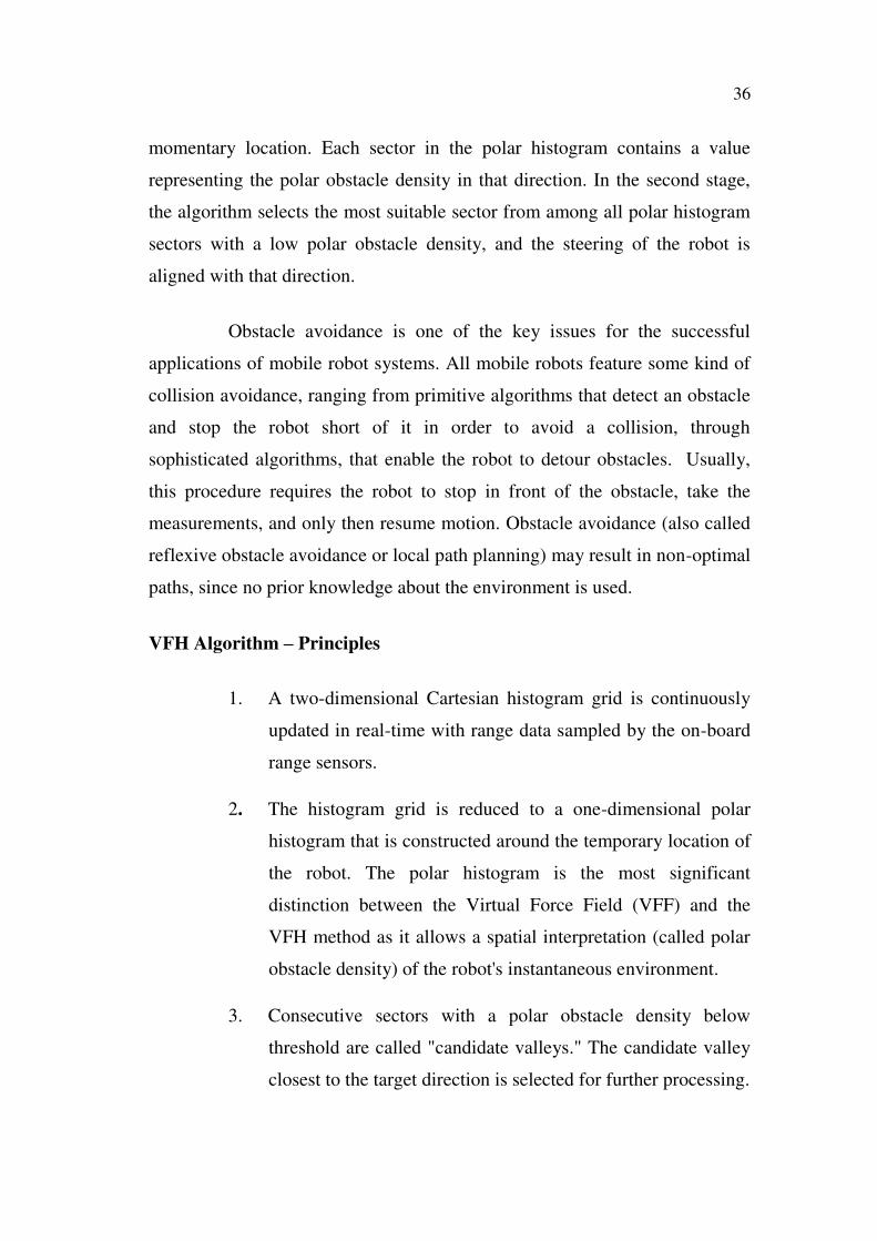
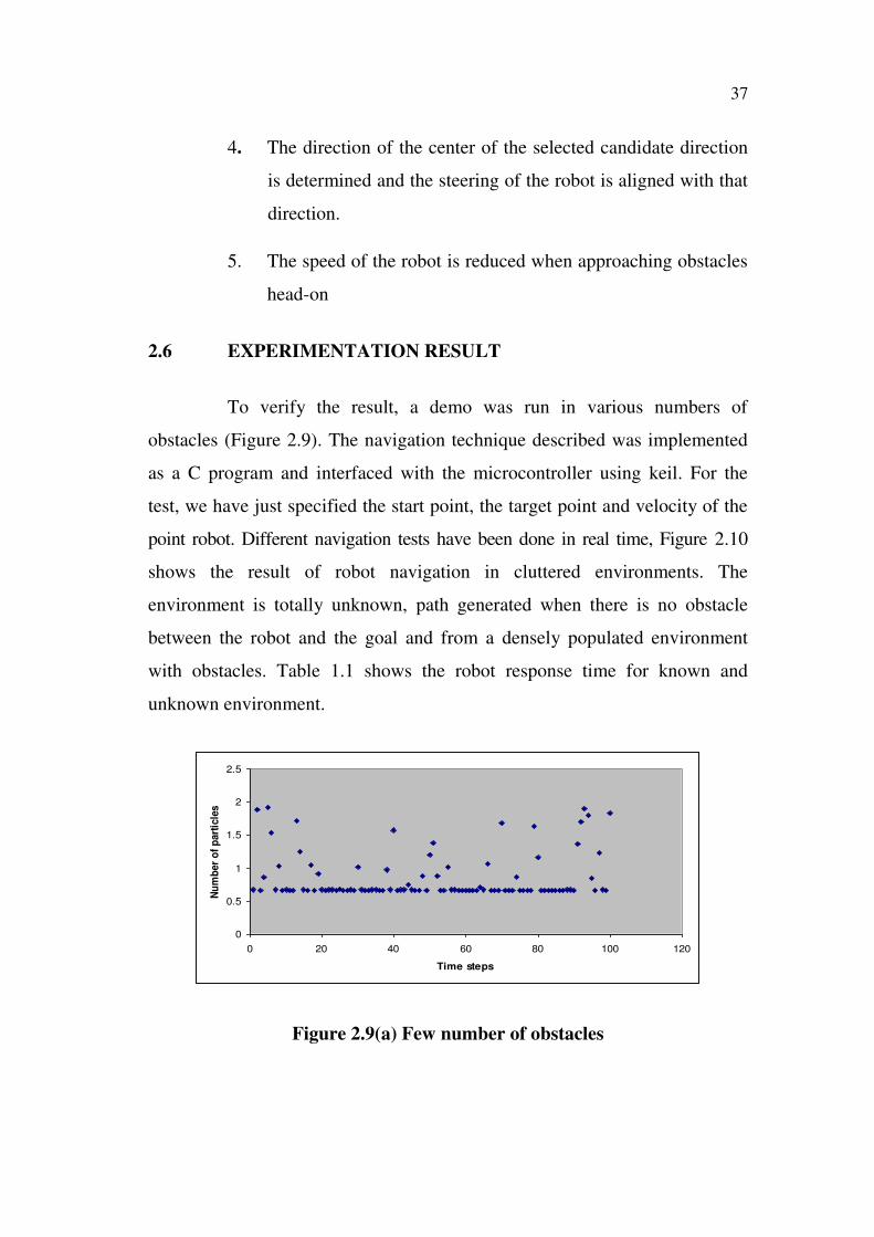
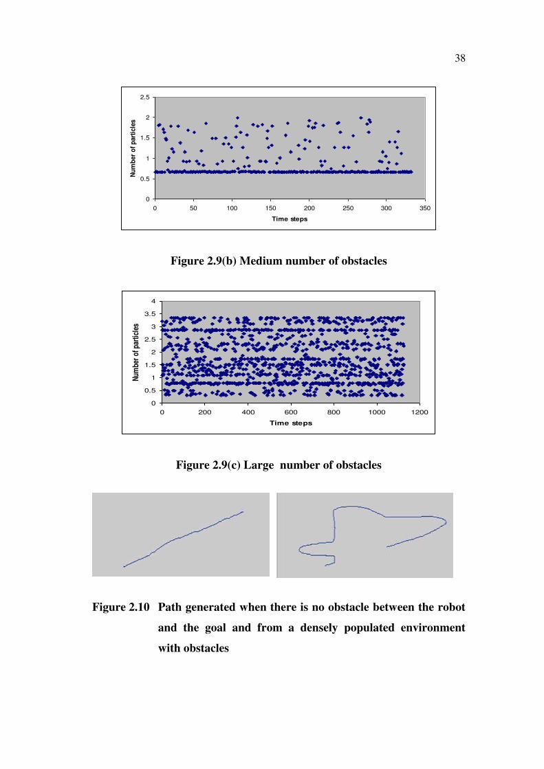
To verify the result, a demo was run in various numbers of
obstacles (Figure 2.9). The navigation technique described was implemented
as a C program and interfaced with the microcontroller using keil. For the
test, we have just specified the start point, the target point and velocity of the
point robot. Different navigation tests have been done in real time, Figure 2.10
shows the result of robot navigation in cluttered environments. The
environment is totally unknown, path generated when there is no obstacle
between the robot and the goal and from a densely populated environment
with obstacles. Table 1.1 shows the robot response time for known and
unknown environment.
0
0.5
1
1.5
2
2.5
0 20 40 60 80 100 120
Time steps
Nu
mb
er
of
part
icle
s
Figure 2.9(a) Few number of obstacles
38
0
0.5
1
1.5
2
2.5
0 50 100 150 200 250 300 350
Time steps
Nu
mb
er
of
part
icle
s
Figure 2.9(b) Medium number of obstacles
0
0.5
1
1.5
2
2.5
3
3.5
4
0 200 400 600 800 1000 1200
Time steps
Num
ber
of p
artic
les
Figure 2.9(c) Large number of obstacles
Figure 2.10 Path generated when there is no obstacle between the robot
and the goal and from a densely populated environment
with obstacles
39
Table 2.1 Response time for known and unknown environment
Fuzzy and VFH
Memory
(Kb)
Time in sec for
Known
environment
Time in sec
for Unknown
environment
10 0.6 5
20 0.8 4.3
30 0.9 3.7
40 1.0 3.2
50 1.1 2.8
60 1.3 2.6
70 1.5 2.5
80 2.0 2.5
90 2.4 2.4
100 2.7 2.2
110 3.0 2
120 3.3 1.9
130 3.3 1.9
2.7 CONCLUSION
The multi-agent and multi-agent optimal path planning approach
provides an extra level intelligence. These techniques deal with the real-time
navigation of a mobile robot in a totally unknown environment. It applies
fuzzy reasoning to endow a mobile robot with ability of the human being to
reason and perceive danger. Based on fuzzy logic, a collision free technique
has been developed that partitions a robot space into eighteen zones of
danger, where just four of them trigger the fuzzy rules. This development had
been validated in different unknown environments cluttered with static and
40
dynamic obstacles and has proven to give the robot, a means of safely
reaching the target. Thus using the different types of sensors the navigation
has been successful even in an unknown environment and the goal has been
reached by the robot without any collisions. The system can be enhanced
further in the future by introducing image processing technique using a
wireless camera to store the navigation path which will be helpful to judge the
navigation path. Also we can implement high range sensors which are capable
of detecting obstacles made up of any material.


![Mobile Robot Navigation using Fuzzy Limit- Cycles in ... · of fuzzy logic in mobile robot navigation, namely, behavior-based approach [22] and classical fuzzy rule based approach](https://img.pdfslide.us/doc/110x75/5eda087bbb309434ee032343/mobile-robot-navigation-using-fuzzy-limit-cycles-in-of-fuzzy-logic-in-mobile.jpg)