Embed Size (px)
Citation preview
Physics Including Human Applications
Chapter 19- Wave Properties of Light
414
Chapter 19 WAVE PROPERTIES OF LIGHT
GOALS When you have mastered the contents of this chapter, you will be able to achieve the following goals: Definitions Define each of the following terms, and use it in an operational definition:
interference optical path length diffraction optical activity dispersion
coherent source polarization noncoherent source birefringence
Application of Wave Properties Explain the physical basis for: thin film colors, polarimetry, diffraction grating spectrometry, holography and resolving power of optical systems Problems Involving Wave Properties Solve problems involving interference, diffraction, and polarization. Optical Activity Design an experimental system capable of measuring the optical activity of a solution. Lasers Compare the laser with other light sources in terms of their optical characteristics.
PREREQUISITES Before you begin this chapter you should have achieved the goals of Chapter 16, Traveling Waves, and Chapter 18, Optical Elements.
Physics Including Human Applications
Chapter 19- Wave Properties of Light
415
Chapter 19 WAVE PROPERTIES OF LIGHT
19.1 Introduction Can you list some of your everyday experiences that are based on the wave properties of light? The colors observed in a soap bubble or an oil film on water are some examples. What wave property of light is involved in these observations? Polaroid sun glasses are designed to reduce glare from reflected light. What wave property of light is used in these glasses? The laser is a new light source that has unique properties; can you name some of these properties? In this chapter we will explore the experimental basis of the wave phenomena of light. We will discuss the questions mentioned here and point out some applications of the wave nature of light.
19.2 Light Waves Light is another example of an interaction-at-a-distance. Once again, as we discussed in Chapter 2, we postulate that the source of light is the source of a field that fills the space between the source and the receiver. We know of properties of light that can be explained as interference or diffraction phenomena. Hence, we construct a model of light as a wave. We shall begin by introducing you to the properties of our wave model of light, and then we shall discuss how this model helps in understanding the various properties of light. In our model light is a transverse electromagnetic wave. Light waves consist of electric and magnetic fields perpendicular to each other oscillating with the wave frequency at right angles to the direction of propagation. The speed of light in a vacuum c is the maximum possible speed for the transmission of energy. (c ≅ 3.0 x 10⁸ m/sec) The speed of light in matter is less than c. The index of refraction of a material is c divided by the speed of light in the material. Since our model for light satisfies the wave equation we have the following relationships: c = fλ, n =c/v = fλo/ (fλ) = λo / λ (19.1) where λ is the wavelength in medium, n is the index of refraction of the medium, f is the frequency of the light wave, and λ 0 is its wavelength in a vacuum. The traditional units
for light wavelengths are angstroms ( ), 1 = 10-10 m, and millimicrons (mµ), 1 mµ = 10-9 m. However in the approved SI, nanometers (1 nm = 10-9
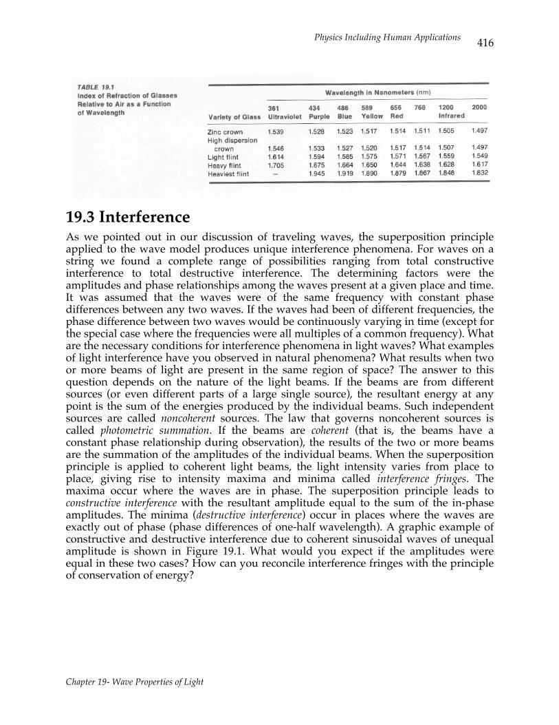
m) are the proper unit to use. The index of refraction for various types of glass is shown in Table 19.1 as a function of the wavelength. The change in the refractive index of a glass with wavelength is called dispersion and shows that light of different wavelengths travels with different speeds in glass. Such glasses are called dispersive media.
Physics Including Human Applications
Chapter 19- Wave Properties of Light
416
19.3 Interference As we pointed out in our discussion of traveling waves, the superposition principle applied to the wave model produces unique interference phenomena. For waves on a string we found a complete range of possibilities ranging from total constructive interference to total destructive interference. The determining factors were the amplitudes and phase relationships among the waves present at a given place and time. It was assumed that the waves were of the same frequency with constant phase differences between any two waves. If the waves had been of different frequencies, the phase difference between two waves would be continuously varying in time (except for the special case where the frequencies were all multiples of a common frequency). What are the necessary conditions for interference phenomena in light waves? What examples of light interference have you observed in natural phenomena? What results when two or more beams of light are present in the same region of space? The answer to this question depends on the nature of the light beams. If the beams are from different sources (or even different parts of a large single source), the resultant energy at any point is the sum of the energies produced by the individual beams. Such independent sources are called noncoherent sources. The law that governs noncoherent sources is called photometric summation. If the beams are coherent (that is, the beams have a constant phase relationship during observation), the results of the two or more beams are the summation of the amplitudes of the individual beams. When the superposition principle is applied to coherent light beams, the light intensity varies from place to place, giving rise to intensity maxima and minima called interference fringes. The maxima occur where the waves are in phase. The superposition principle leads to constructive interference with the resultant amplitude equal to the sum of the in-phase amplitudes. The minima (destructive interference) occur in places where the waves are exactly out of phase (phase differences of one-half wavelength). A graphic example of constructive and destructive interference due to coherent sinusoidal waves of unequal amplitude is shown in Figure 19.1. What would you expect if the amplitudes were equal in these two cases? How can you reconcile interference fringes with the principle of conservation of energy?
Physics Including Human Applications
Chapter 19- Wave Properties of Light
417
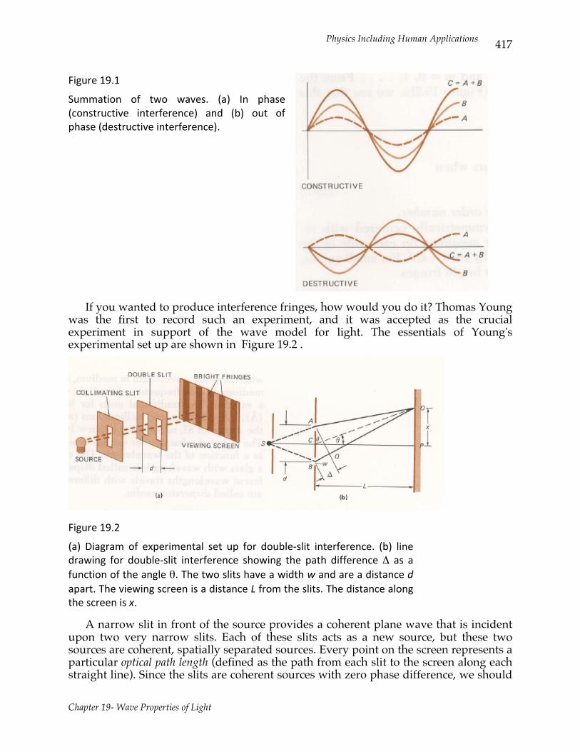
Figure 19.1
Summation of two waves. (a) In phase (constructive interference) and (b) out of phase (destructive interference).
If you wanted to produce interference fringes, how would you do it? Thomas Young was the first to record such an experiment, and it was accepted as the crucial experiment in support of the wave model for light. The essentials of Young's experimental set up are shown in Figure 19.2 .
Figure 19.2
(a) Diagram of experimental set up for double-‐slit interference. (b) line drawing for double-‐slit interference showing the path difference Δ as a function of the angle θ. The two slits have a width w and are a distance d apart. The viewing screen is a distance L from the slits. The distance along the screen is x.
A narrow slit in front of the source provides a coherent plane wave that is incident upon two very narrow slits. Each of these slits acts as a new source, but these two sources are coherent, spatially separated sources. Every point on the screen represents a particular optical path length (defined as the path from each slit to the screen along each straight line). Since the slits are coherent sources with zero phase difference, we should
Physics Including Human Applications
Chapter 19- Wave Properties of Light
418
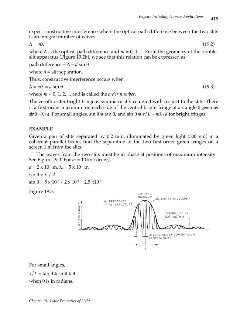
expect constructive interference where the optical path difference between the two slits is an integral number of waves. Δ = mλ (19.2) where Δ is the optical path difference and m = 0, 1, ... From the geometry of the double-slit apparatus (Figure 19.2b), we see that this relation can be expressed as: path difference = Δ = d sin θ where d = slit separation. Thus, constructive interference occurs when Δ = mλ = d sin θ (19.3) where m = 0, 1, 2, ... and is called the order number. The zeroth order bright fringe is symmetrically centered with respect to the slits. There is a first-order maximum on each side of the central bright fringe at an angle θ given by sinθ =λ/d. For small angles, sin θ ≅ tan θ, and sin θ ≅ x/L = mλ/d for bright fringes. EXAMPLE Given a pair of slits separated by 0.2 mm, illuminated by green light (500 nm) in a coherent parallel beam, find the separation of the two first-order green fringes on a screen 1 m from the slits. The waves from the two slits must be in phase at positions of maximum intensity. See Figure 19.3. For m = 1 (first order), d = 2 x 10⁻⁴ m, λo = 5 x 10⁻⁷ m sin θ = λ / d sin θ = 5 x 10⁻⁷ / 2 x 10-4 = 2.5 x10⁻³
Figure 19.3.
For small angles,
x/L = tan θ ≅ sinθ ≅ θ when θ is in radians.
Physics Including Human Applications
Chapter 19- Wave Properties of Light
419
We want to find two times the distance between central bright and the first maxima on either side of the central bright fringe, 2x = 2 x 102 cm x 2.5 x 10-3
x = 5 x 10⁻¹ cm = 5 mm
19.4 Effective Optical Path Lengths Young's experiments show that it is possible to set up interference fringes by introducing optical path differences between coherent wave trains. In Young's experiments the path differences were in air, and we did not correct for the difference of the wavelength in a vacuum and the wavelength in air. (If n = 1.0003 for air, what is the error in neglecting this wavelength change?) Effective optical path lengths in materials involve the wavelength of white light in the medium. For example, the path differences for constructive interference must be an integral number of waves in the given material. Since the wavelength of light in a material with an index of refraction n is given by its wavelength in a vacuum λ0 divided by n, then a thickness t of this material is equivalent to nt/λ0 wavelengths. This means that the effective optical path length for a sample of thickness t with an index of refraction n is nt: optical path length = nt (19.4) EXAMPLE Compare the effective optical path of 10-6 m in a vacuum, air and water. 10-6 m (vacuum) = 1.0003 x 10⁻⁶ m (air) = 1.3333 x 10⁻⁶ m (water)
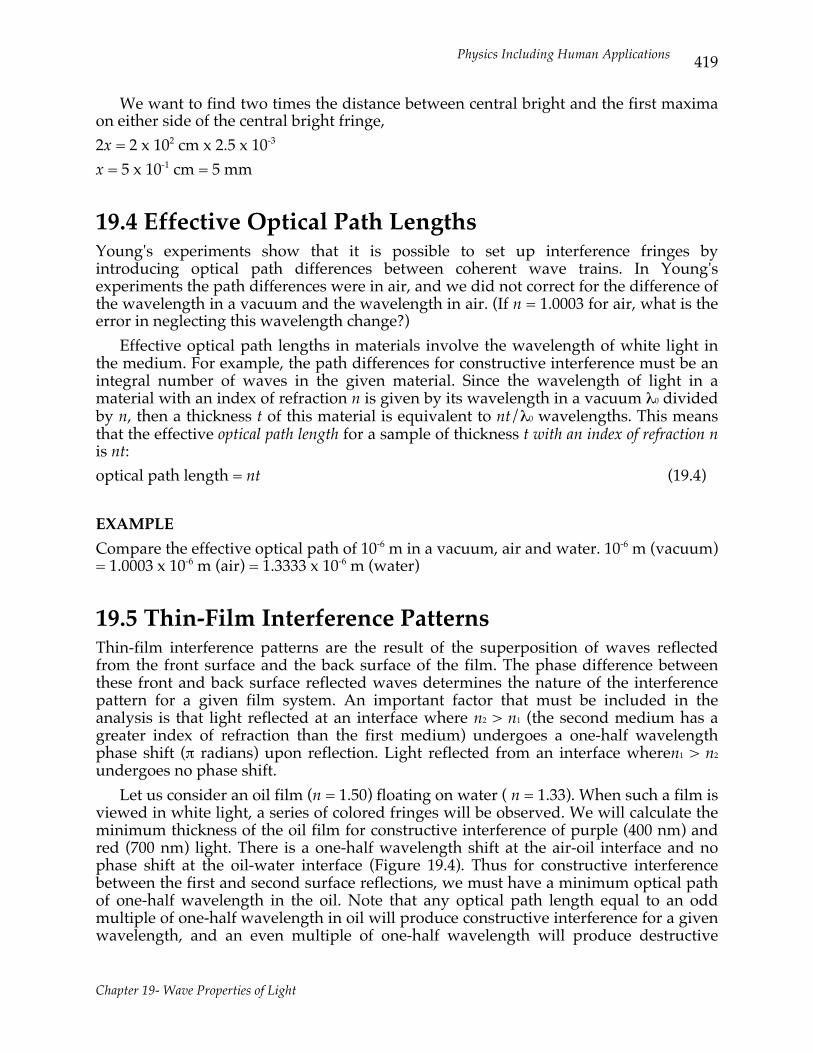
19.5 Thin-Film Interference Patterns Thin-film interference patterns are the result of the superposition of waves reflected from the front surface and the back surface of the film. The phase difference between these front and back surface reflected waves determines the nature of the interference pattern for a given film system. An important factor that must be included in the analysis is that light reflected at an interface where n2 > n1 (the second medium has a greater index of refraction than the first medium) undergoes a one-half wavelength phase shift (π radians) upon reflection. Light reflected from an interface wheren1 > n2 undergoes no phase shift. Let us consider an oil film (n = 1.50) floating on water ( n = 1.33). When such a film is viewed in white light, a series of colored fringes will be observed. We will calculate the minimum thickness of the oil film for constructive interference of purple (400 nm) and red (700 nm) light. There is a one-half wavelength shift at the air-oil interface and no phase shift at the oil-water interface (Figure 19.4). Thus for constructive interference between the first and second surface reflections, we must have a minimum optical path of one-half wavelength in the oil. Note that any optical path length equal to an odd multiple of one-half wavelength in oil will produce constructive interference for a given wavelength, and an even multiple of one-half wavelength will produce destructive
Physics Including Human Applications
Chapter 19- Wave Properties of Light
420
interference. The effective optical path difference between the front and back surface reflections is 2tnoil, where t is the film thickness. Light reflected from the second surface travels a distance of 2t in the oil. Thus the condition for constructive interference can be expressed as 2tn = (m/2)λo (19.5) for m = 1, 3, 5, ... (constructive) and m = 2, 4, 6, ... (destructive), where t = film thickness andn is the index of refraction of the film, or t(purple) = λo/4n = 400 nm/6 = 66.7 nm t(red) = 700 nm /6 = 116 nm
Consider the similar problem for an oil film suspended on a wire frame in air. The colors of some insect wings are due to such interference phenomena. (What information about insect wings could you obtain by studying these color fringes? What experiments would you do?)
19.6 The Interference Microscope The interference microscope is designed to convert the phase difference introduced by the different optical path length through the specimen and through the surrounding fluid into a difference in intensity that can be detected by the observer. This is done by taking a parallel coherent beam that passes only through the air and making it π radians (1/2 wavelength) out of phase with the beam passing through the fluid alone. These two beams produce destructive interference on a view screen. Any light passing through the specimen will introduce an additional phase shift. The phase shift Δθ is given by
Physics Including Human Applications
Chapter 19- Wave Properties of Light
421
Δθ = 2π (ns -nf) t/λo (19.6) where ns = specimen index and n f = fluid index. At places where Δθ = 2π there will be constructive interference and as the specimen thickness varies, intensity variations occur that make the specimen visible on the screen.
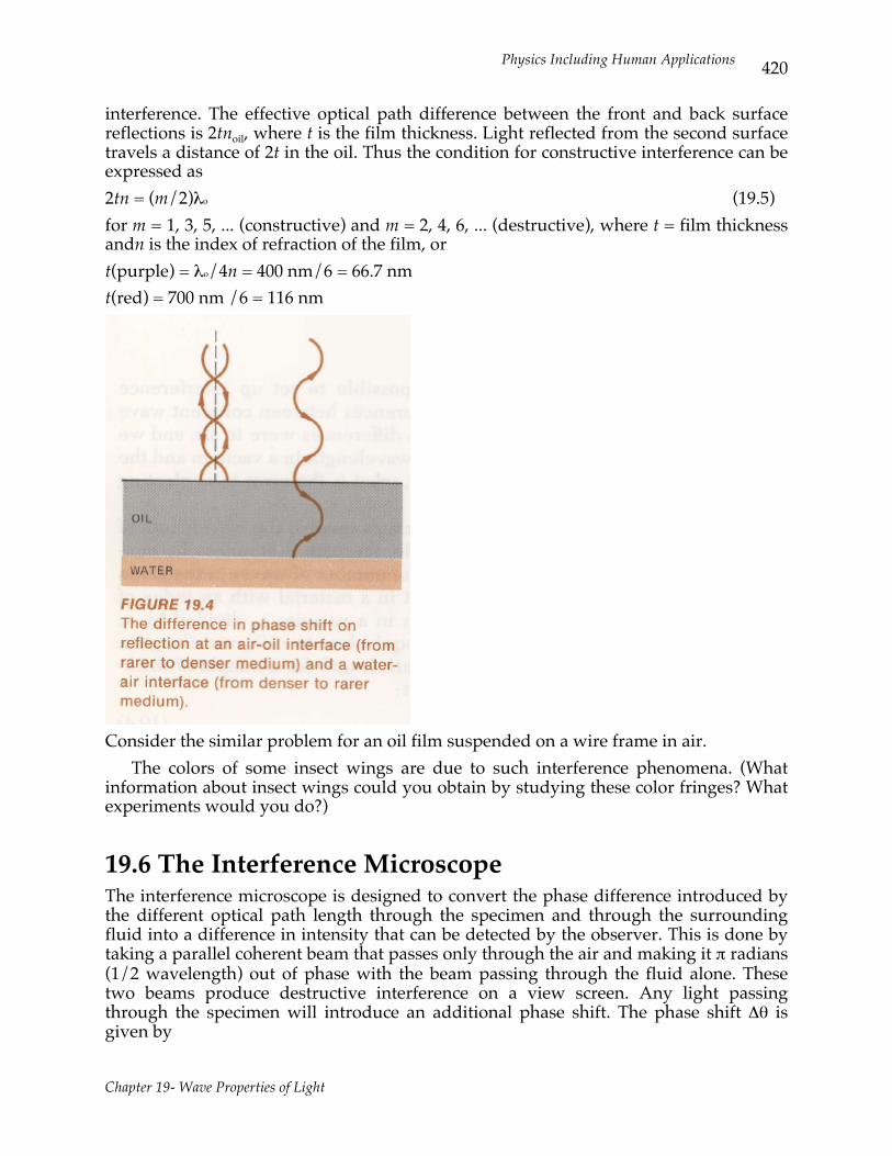
19.7 Diffraction The bending of waves around objects is common to all wave motion. This wave phenomenon is called diffraction. Diffraction patterns result from the interference of waves that travel different distances around objects or through apertures. Consider the diffraction due to a single slit as shown in Figure 19.5a . To derive the conditions for destructive interference we divide the slit of width w into two equal zones (see Figure 19.5b). For destructive interference the waves from zone A cancel the waves from zone B in pairs. The path difference for these cancelling pairs results in the following condition for first-order minima: (w/2) sinθ = λ/2 for the first-order minima on either side of the central bright band.
Higher-order minima are given by path differences equal to odd multiples of one-half wavelength. This general condition for single- slit diffraction minima can be expressed as w sin θ = mλ (19.7) where m = 1,3,5, ... is the order of the minimum and w is the width of the slit.

Physics Including Human Applications
Chapter 19- Wave Properties of Light
422
EXAMPLE Find the separation of the two second-order minima for red (600 nm) parallel light incident on a slit of 0.100 mm width which is 1.00 m from the viewing screen. w sin θ = 2λ sin θ = 2 x 6.00 x 10-7 m/10-4 = 12.0 x 10-3
Let x2 be the distance along the screen from the central maximum to the second order minimum, for small angles
sin θ ≅ x2 / L so x2 = 12.0 x 10⁻³ m and the separation between the two second-order minima is 2x2 = 24 x 10-3 m = 0.024 m.
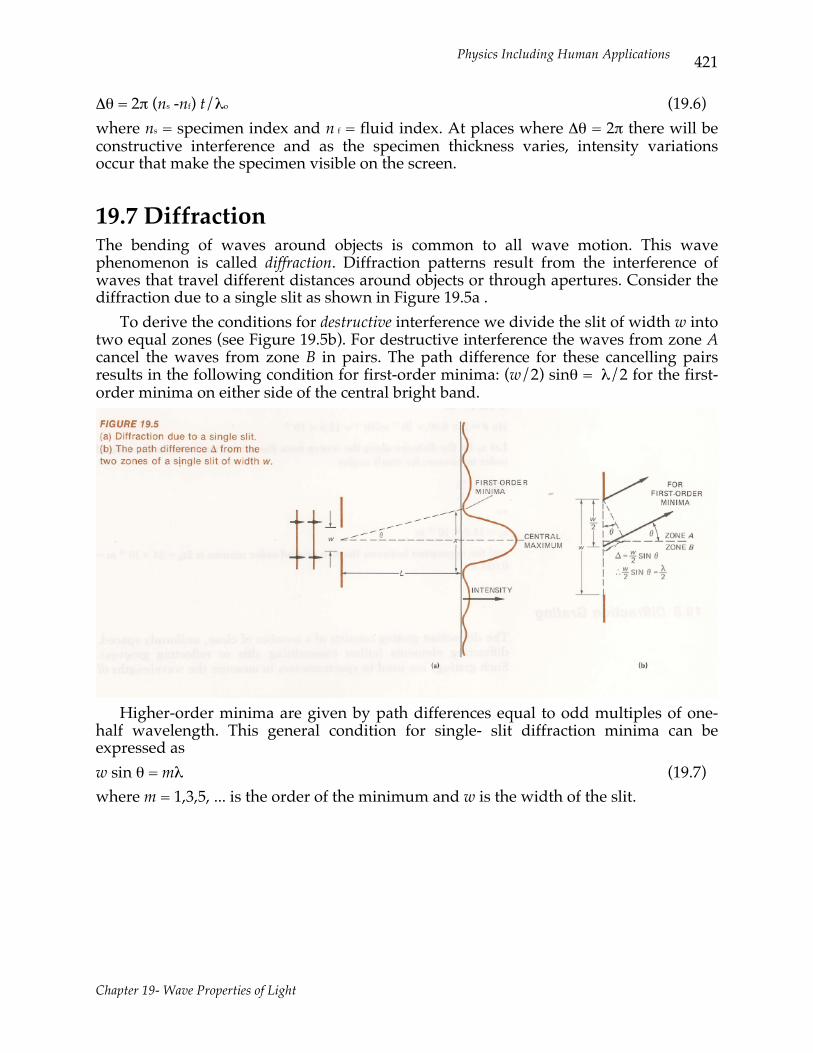
19.8 Diffraction Grating The diffraction grating consists of a number of close, uniformly spaced, diffracting elements (either transmitting slits or reflecting grooves). Such gratings are used in spectrometers to measure the wavelengths of spectra. The diffraction pattern produced by a granting is the result of the interference of the waves from the different diffracting elements. A diagram of a diffracting grating is shown in Figure 19.6. Constructive interference occurs when the waves from adjacent elements have path differences of an integral number of wavelengths between the grating and screen. The equation expressing this condition is: d sin θ = mλ (19.3) where m = 1, 2, 3,... and is the order of the diffraction maxima, where d is the distance between the slits and is considered to be much larger than the width of each slit.
Physics Including Human Applications
Chapter 19- Wave Properties of Light
423
Figure 19.6
A diffraction grating, a screen with many fine slits equally spaced a distance d apart.
EXAMPLE Find the angular spread of the first-order visible spectrum from a grating with a number of lines per unit length N of 10,000 lines/cm. The visible spectrum range is from 400 nm (purple) to 700 nm (red). d = 1/N = 10-4 cm sin θ (purple) = 4 x 10⁻⁵ cm/10-4 cm = 0.4 θ (purple) = 23.6° sin θ (red) = 7 x 10⁻⁵ cm/10-4 cm = 0.7 θ (red) = 44.6° Δθ = θ (red) - θ (purple) = 21° angular spread of first-order visible spectrum
19.9 Resolution Factors The ability of a grating to separate two wavelengths increases as the order increases. However, there are problems concerning intensity and orders that overlap in high-order spectra. The intensity of the diffraction decreases with increasing order. In addition, the overlap for a given grating produces a higher-order, shorter- wavelength line between lower-order, longer-wavelength lines in the spectra under observation. For example, third-order 400-nm light will be at same angle as second-order 600-nm light. Thus, the use of higher orders to improve resolution involves a compromise to solve the resolution problem. We have ignored the single slit patterns that are superimposed for the actual grating. Our treatment has assumed that the individual slits have widths approximately equal to the wavelength of light. The limiting factor in the resolving power of an optical instrument is the diffraction pattern produced by the system. The apertures of optical instruments produce diffraction patterns of point sources. The resolving power of an optical system is measured by the minimum angle subtended by two just resolvable sources of light. The "just resolvable" criterion we use is called the Rayleigh criterion. Lord Rayleigh suggested that two images are just resolvable if the central maximum of one source is
Physics Including Human Applications
Chapter 19- Wave Properties of Light
424
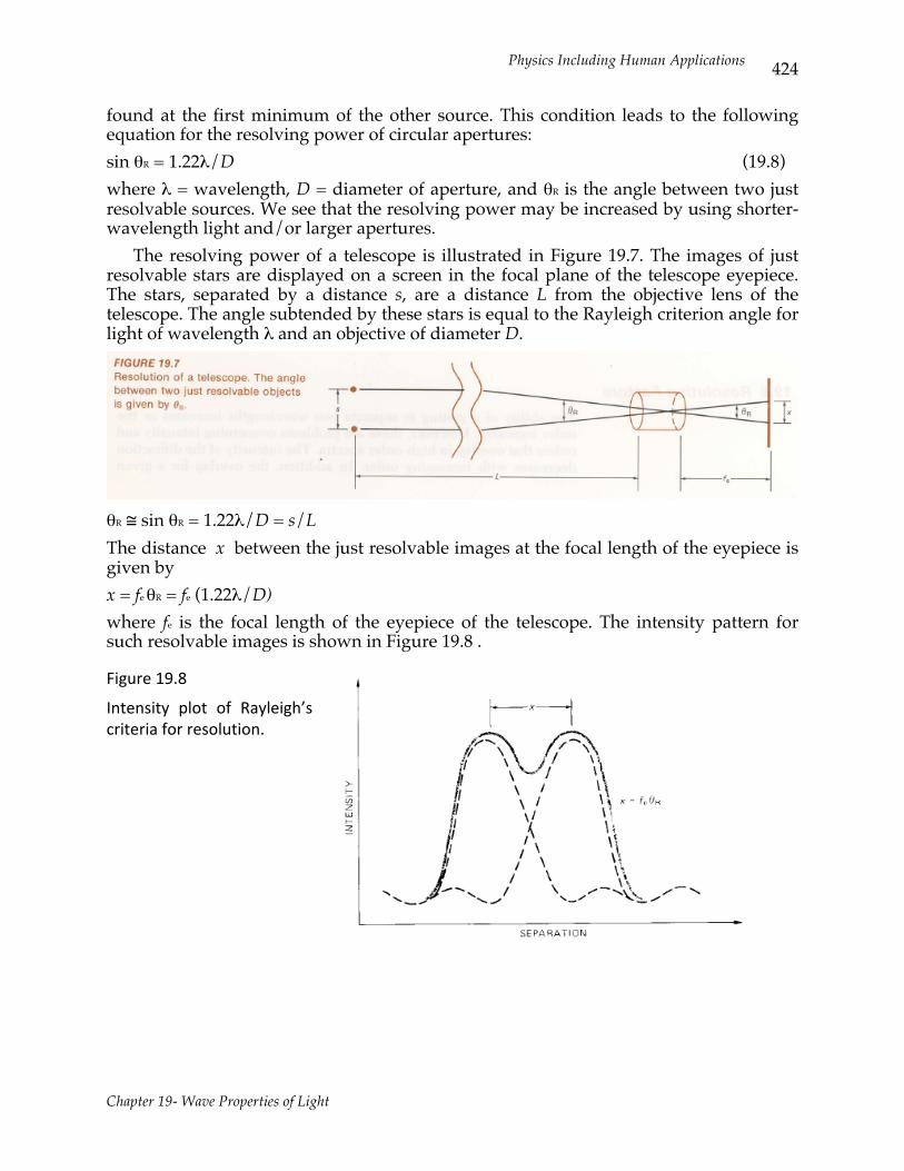
found at the first minimum of the other source. This condition leads to the following equation for the resolving power of circular apertures: sin θR = 1.22λ/D (19.8) where λ = wavelength, D = diameter of aperture, and θR is the angle between two just resolvable sources. We see that the resolving power may be increased by using shorter-wavelength light and/or larger apertures. The resolving power of a telescope is illustrated in Figure 19.7. The images of just resolvable stars are displayed on a screen in the focal plane of the telescope eyepiece. The stars, separated by a distance s, are a distance L from the objective lens of the telescope. The angle subtended by these stars is equal to the Rayleigh criterion angle for light of wavelength λ and an objective of diameter D.
θR ≅ sin θR = 1.22λ/D = s/L The distance x between the just resolvable images at the focal length of the eyepiece is given by x = fe θR = fe (1.22λ/D) where fe is the focal length of the eyepiece of the telescope. The intensity pattern for such resolvable images is shown in Figure 19.8 .
Figure 19.8
Intensity plot of Rayleigh’s criteria for resolution.
Physics Including Human Applications
Chapter 19- Wave Properties of Light
425
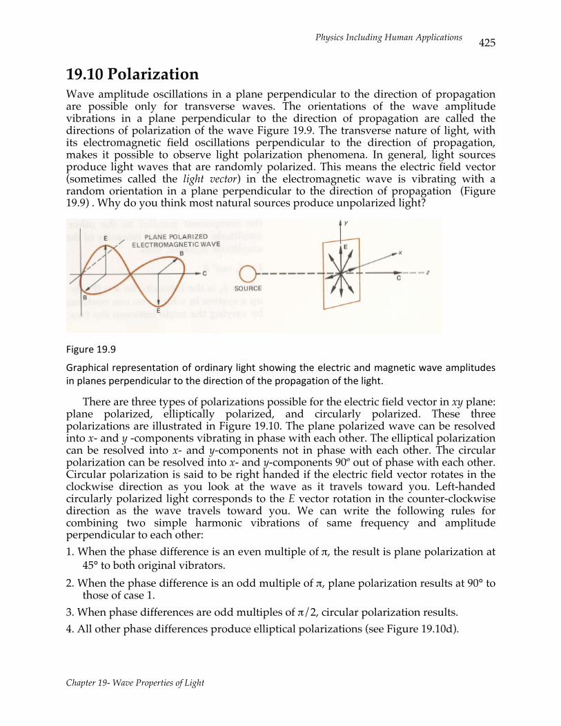
19.10 Polarization Wave amplitude oscillations in a plane perpendicular to the direction of propagation are possible only for transverse waves. The orientations of the wave amplitude vibrations in a plane perpendicular to the direction of propagation are called the directions of polarization of the wave Figure 19.9. The transverse nature of light, with its electromagnetic field oscillations perpendicular to the direction of propagation, makes it possible to observe light polarization phenomena. In general, light sources produce light waves that are randomly polarized. This means the electric field vector (sometimes called the light vector) in the electromagnetic wave is vibrating with a random orientation in a plane perpendicular to the direction of propagation (Figure 19.9) . Why do you think most natural sources produce unpolarized light?
Figure 19.9
Graphical representation of ordinary light showing the electric and magnetic wave amplitudes in planes perpendicular to the direction of the propagation of the light.
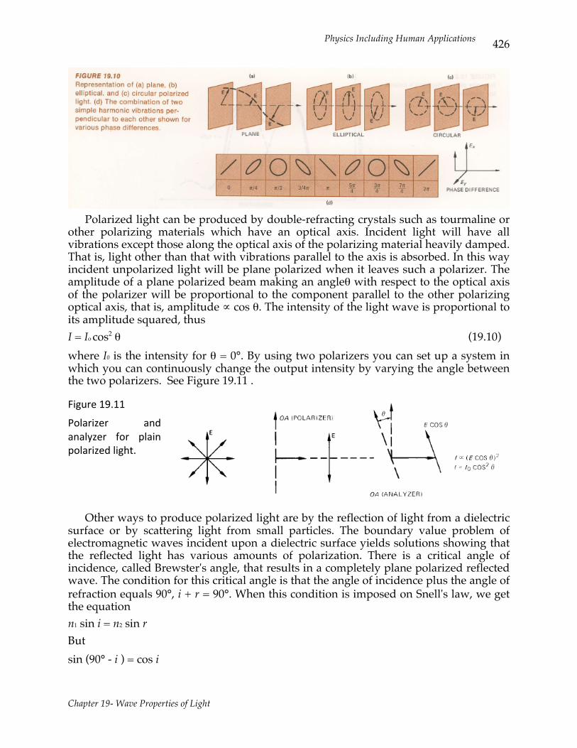
There are three types of polarizations possible for the electric field vector in xy plane: plane polarized, elliptically polarized, and circularly polarized. These three polarizations are illustrated in Figure 19.10. The plane polarized wave can be resolved into x- and y -components vibrating in phase with each other. The elliptical polarization can be resolved into x- and y-components not in phase with each other. The circular polarization can be resolved into x- and y-components 90ø out of phase with each other. Circular polarization is said to be right handed if the electric field vector rotates in the clockwise direction as you look at the wave as it travels toward you. Left-handed circularly polarized light corresponds to the E vector rotation in the counter-clockwise direction as the wave travels toward you. We can write the following rules for combining two simple harmonic vibrations of same frequency and amplitude perpendicular to each other: 1. When the phase difference is an even multiple of π, the result is plane polarization at
45° to both original vibrators. 2. When the phase difference is an odd multiple of π, plane polarization results at 90° to
those of case 1. 3. When phase differences are odd multiples of π/2, circular polarization results. 4. All other phase differences produce elliptical polarizations (see Figure 19.10d).
Physics Including Human Applications
Chapter 19- Wave Properties of Light
426
Polarized light can be produced by double-refracting crystals such as tourmaline or other polarizing materials which have an optical axis. Incident light will have all vibrations except those along the optical axis of the polarizing material heavily damped. That is, light other than that with vibrations parallel to the axis is absorbed. In this way incident unpolarized light will be plane polarized when it leaves such a polarizer. The amplitude of a plane polarized beam making an angleθ with respect to the optical axis of the polarizer will be proportional to the component parallel to the other polarizing optical axis, that is, amplitude ∝ cos θ. The intensity of the light wave is proportional to its amplitude squared, thus I = Io cos2 θ (19.10) where I0 is the intensity for θ = 0°. By using two polarizers you can set up a system in which you can continuously change the output intensity by varying the angle between the two polarizers. See Figure 19.11 .
Figure 19.11
Polarizer and analyzer for plain polarized light.
Other ways to produce polarized light are by the reflection of light from a dielectric surface or by scattering light from small particles. The boundary value problem of electromagnetic waves incident upon a dielectric surface yields solutions showing that the reflected light has various amounts of polarization. There is a critical angle of incidence, called Brewster's angle, that results in a completely plane polarized reflected wave. The condition for this critical angle is that the angle of incidence plus the angle of refraction equals 90°, i + r = 90°. When this condition is imposed on Snell's law, we get the equation n1 sin i = n2 sin r But sin (90° - i ) = cos i
Physics Including Human Applications
Chapter 19- Wave Properties of Light
427
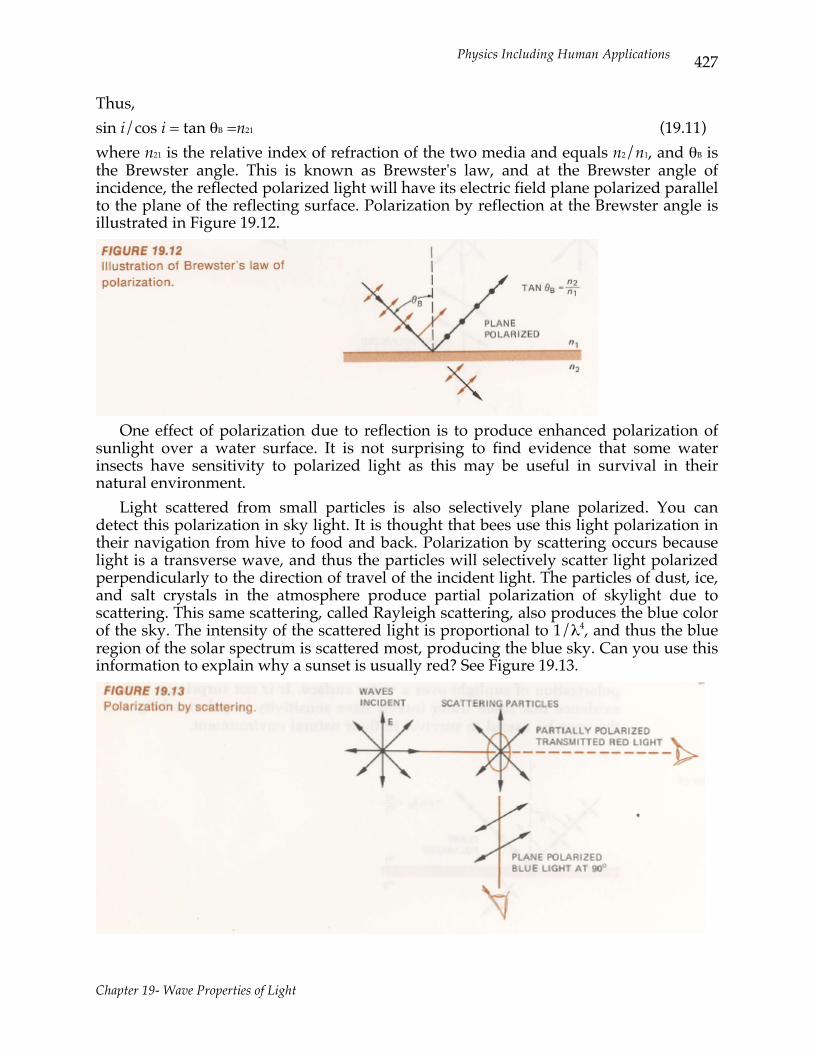
Thus, sin i/cos i = tan θB =n21 (19.11) where n21 is the relative index of refraction of the two media and equals n2/n1, and θB is the Brewster angle. This is known as Brewster's law, and at the Brewster angle of incidence, the reflected polarized light will have its electric field plane polarized parallel to the plane of the reflecting surface. Polarization by reflection at the Brewster angle is illustrated in Figure 19.12.
One effect of polarization due to reflection is to produce enhanced polarization of sunlight over a water surface. It is not surprising to find evidence that some water insects have sensitivity to polarized light as this may be useful in survival in their natural environment. Light scattered from small particles is also selectively plane polarized. You can detect this polarization in sky light. It is thought that bees use this light polarization in their navigation from hive to food and back. Polarization by scattering occurs because light is a transverse wave, and thus the particles will selectively scatter light polarized perpendicularly to the direction of travel of the incident light. The particles of dust, ice, and salt crystals in the atmosphere produce partial polarization of skylight due to scattering. This same scattering, called Rayleigh scattering, also produces the blue color of the sky. The intensity of the scattered light is proportional to 1/λ4, and thus the blue region of the solar spectrum is scattered most, producing the blue sky. Can you use this information to explain why a sunset is usually red? See Figure 19.13.
Physics Including Human Applications
Chapter 19- Wave Properties of Light
428
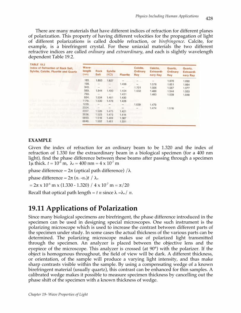
There are many materials that have different indices of refraction for different planes of polarization. This property of having different velocities for the propagation of light of different polarizations is called double refraction, or birefringence. Calcite, for example, is a birefringent crystal. For these uniaxial materials the two different refractive indices are called ordinary and extraordinary, and each is slightly wavelength dependent Table 19.2.
EXAMPLE Given the index of refraction for an ordinary beam to be 1.320 and the index of refraction of 1.330 for the extraordinary beam in a biological specimen (for a 400 nm light), find the phase difference between these beams after passing through a specimen 1µ thick. t = 10-6 m, λ0 = 400 nm = 4 x 10⁻⁷ m phase difference = 2π (optical path difference) /λ phase difference = 2π (nc -no)t / λo = 2π x 10-6 m x (1.330 - 1.320) / 4 x 10⁻⁷ m = π/20 Recall that optical path length = t n since λ =λo/ n.
19.11 Applications of Polarization Since many biological specimens are birefringent, the phase difference introduced in the specimen can be used in designing special microscopes. One such instrument is the polarizing microscope which is used to increase the contrast between different parts of the specimen under study. In some cases the actual thickness of the various parts can be determined. The polarizing microscope makes use of polarized light transmitted through the specimen. An analyzer is placed between the objective lens and the eyepiece of the microscope. This analyzer is crossed (at 90°) with the polarizer. If the object is homogenous throughout, the field of view will be dark. A different thickness, or orientation, of the sample will produce a varying light intensity, and thus make sharp contrasts visible within the sample. By using a compensating wedge of a known birefringent material (usually quartz), this contrast can be enhanced for thin samples. A calibrated wedge makes it possible to measure specimen thickness by cancelling out the phase shift of the specimen with a known thickness of wedge.
Physics Including Human Applications
Chapter 19- Wave Properties of Light
429
19.12 Optically Active Materials Some substances (especially in living systems) have the property which causes the plane of polarization of light to be rotated as it passes through them. Such materials are called optically active materials. There are both right- and left-handed substances that rotate the plane of polarization in opposite directions. Sugar is found in both forms, right-handed dextrose and left-handed levulose. The optical activity is demonstrated by solutions of these materials. The optical activity of a solution is proportional to the concentration of optically active molecules in the solution and the length of the light path through the solution. The angle of rotation of plane of polarization θ is given by θ = KLc (19.12) where K = proportionality constant for a given substance, L = path length, and c = concentration of optically active material. This equation can be used with appropriate instruments such as a polarimeter or saccharimeter to measure unknown concentrations of optically active substances. Polarized light is passed through the sample and the angle through which the analyzer must be rotated to achieve extinction is measured. EXAMPLE A concentration of dextrose of 1.00 g/cm3 produces a rotation of 5.3°/cm of path. If light passing through 10.0 cm of an unknown dextrose solution is rotated through 8.3 degrees, find the concentration of the unknown. If 5.3° = K x 1 (cm) x 1.00 (g/cm3), and 8.3° = K x 10.0 (cm) x c (g/cm3) then 5.3 / 8.3 = 1.00 (gm/cm3) / 10.0 c or c = 8.30 / 53.0 = 0.156 g/cm3
19.13 Lasers and Laser Applications In general, the light from a single light source consists of a series of random wave trains. Each wave train lasts for about 10-9 sec, and thus a wave train is approximately 30 cm long. Since these wave trains are uncorrelated with each other in phase, they are noncoherent. Light from different sources is also noncoherent. The development of the laser has provided a high intensity, monochromatic, highly directional, coherent source of light. The laser produces a continuous train of waves. The actual wave train from a laser is approximately 30 m long. The laser beam is highly correlated in space and time. Laser is an acronym for light amplified by the stimulated emission of radiation. There are many different kinds of lasers available today, but the physical basis of each is essentially the same. We will outline the basic physics involved in the operation of the laser in the chapter on atomic physics (Chapter 28). There are many applications of lasers because of their unique properties as light sources. Their high intensity and extreme directionality has made them ideal for alignment and communication applications. The laser beam can be focused by optical lenses. It is possible to produce power concentrations greater than 109 watts/cm3 at the focal point of a lens. Such power levels enable lasers to be used for cutting materials (for
Physics Including Human Applications
Chapter 19- Wave Properties of Light
430
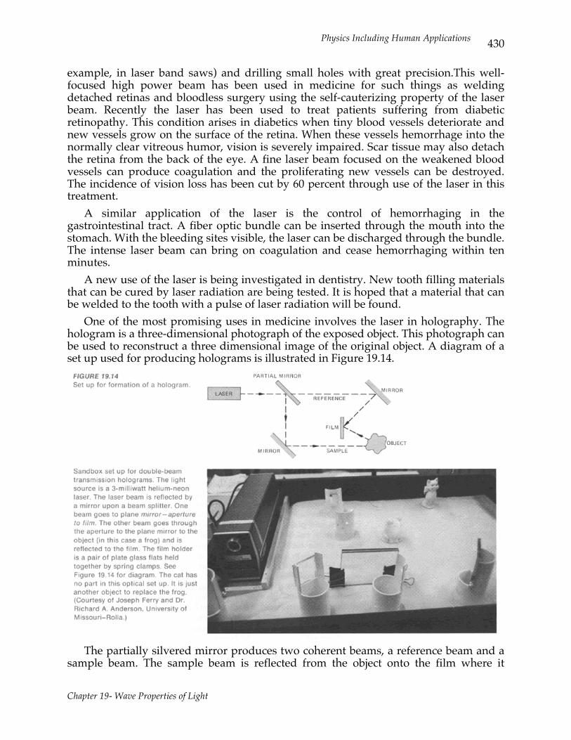
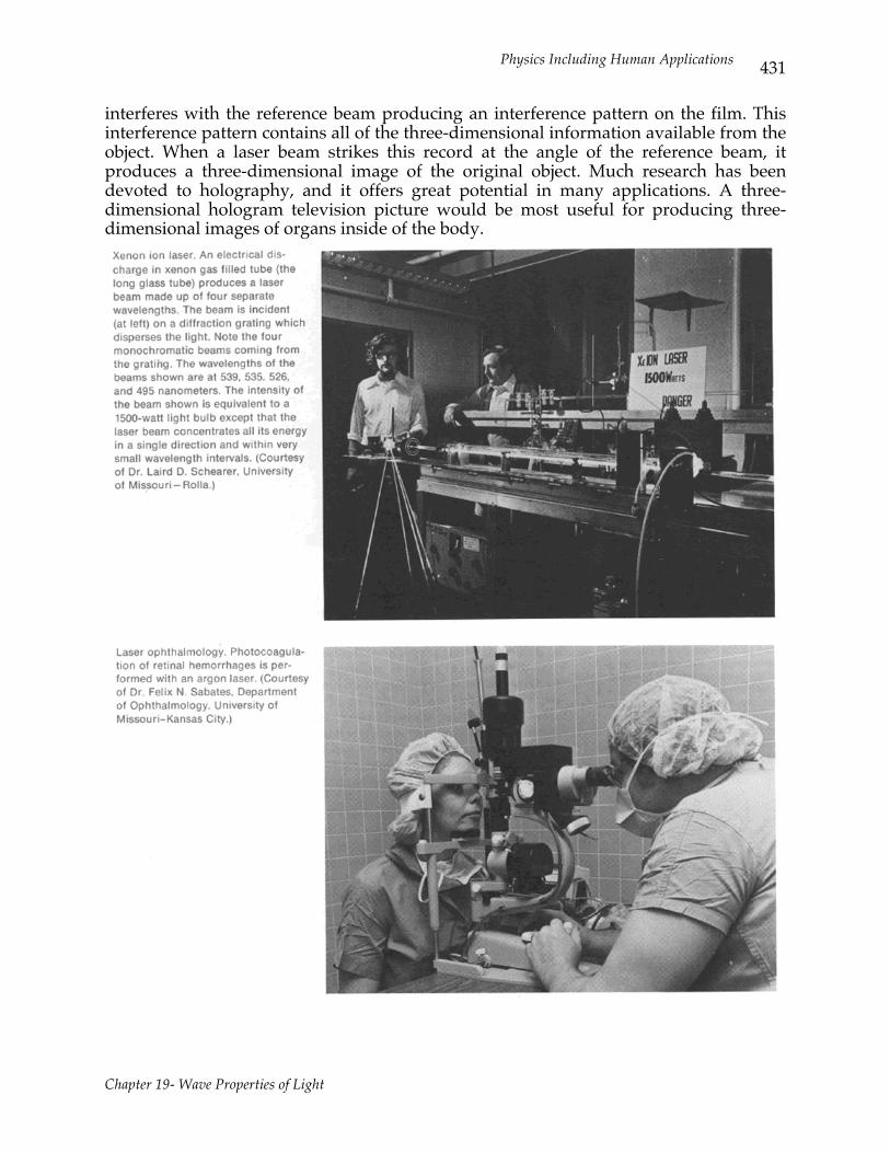
example, in laser band saws) and drilling small holes with great precision.This well-focused high power beam has been used in medicine for such things as welding detached retinas and bloodless surgery using the self-cauterizing property of the laser beam. Recently the laser has been used to treat patients suffering from diabetic retinopathy. This condition arises in diabetics when tiny blood vessels deteriorate and new vessels grow on the surface of the retina. When these vessels hemorrhage into the normally clear vitreous humor, vision is severely impaired. Scar tissue may also detach the retina from the back of the eye. A fine laser beam focused on the weakened blood vessels can produce coagulation and the proliferating new vessels can be destroyed. The incidence of vision loss has been cut by 60 percent through use of the laser in this treatment. A similar application of the laser is the control of hemorrhaging in the gastrointestinal tract. A fiber optic bundle can be inserted through the mouth into the stomach. With the bleeding sites visible, the laser can be discharged through the bundle. The intense laser beam can bring on coagulation and cease hemorrhaging within ten minutes. A new use of the laser is being investigated in dentistry. New tooth filling materials that can be cured by laser radiation are being tested. It is hoped that a material that can be welded to the tooth with a pulse of laser radiation will be found. One of the most promising uses in medicine involves the laser in holography. The hologram is a three-dimensional photograph of the exposed object. This photograph can be used to reconstruct a three dimensional image of the original object. A diagram of a set up used for producing holograms is illustrated in Figure 19.14.
The partially silvered mirror produces two coherent beams, a reference beam and a sample beam. The sample beam is reflected from the object onto the film where it
Physics Including Human Applications
Chapter 19- Wave Properties of Light
431
interferes with the reference beam producing an interference pattern on the film. This interference pattern contains all of the three-dimensional information available from the object. When a laser beam strikes this record at the angle of the reference beam, it produces a three-dimensional image of the original object. Much research has been devoted to holography, and it offers great potential in many applications. A three-dimensional hologram television picture would be most useful for producing three-dimensional images of organs inside of the body.
Physics Including Human Applications
Chapter 19- Wave Properties of Light
432
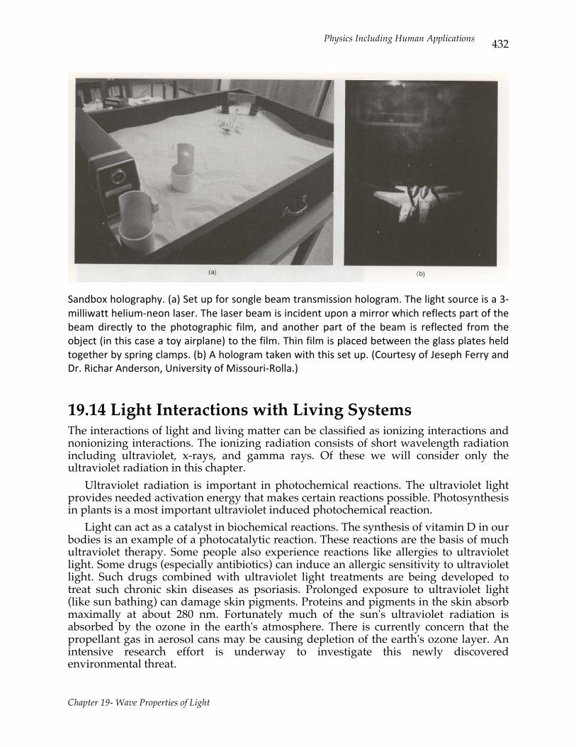
Sandbox holography. (a) Set up for songle beam transmission hologram. The light source is a 3-‐milliwatt helium-‐neon laser. The laser beam is incident upon a mirror which reflects part of the beam directly to the photographic film, and another part of the beam is reflected from the object (in this case a toy airplane) to the film. Thin film is placed between the glass plates held together by spring clamps. (b) A hologram taken with this set up. (Courtesy of Jeseph Ferry and Dr. Richar Anderson, University of Missouri-‐Rolla.)
19.14 Light Interactions with Living Systems The interactions of light and living matter can be classified as ionizing interactions and nonionizing interactions. The ionizing radiation consists of short wavelength radiation including ultraviolet, x-rays, and gamma rays. Of these we will consider only the ultraviolet radiation in this chapter. Ultraviolet radiation is important in photochemical reactions. The ultraviolet light provides needed activation energy that makes certain reactions possible. Photosynthesis in plants is a most important ultraviolet induced photochemical reaction. Light can act as a catalyst in biochemical reactions. The synthesis of vitamin D in our bodies is an example of a photocatalytic reaction. These reactions are the basis of much ultraviolet therapy. Some people also experience reactions like allergies to ultraviolet light. Some drugs (especially antibiotics) can induce an allergic sensitivity to ultraviolet light. Such drugs combined with ultraviolet light treatments are being developed to treat such chronic skin diseases as psoriasis. Prolonged exposure to ultraviolet light (like sun bathing) can damage skin pigments. Proteins and pigments in the skin absorb maximally at about 280 nm. Fortunately much of the sun's ultraviolet radiation is absorbed by the ozone in the earth's atmosphere. There is currently concern that the propellant gas in aerosol cans may be causing depletion of the earth's ozone layer. An intensive research effort is underway to investigate this newly discovered environmental threat.
Physics Including Human Applications
Chapter 19- Wave Properties of Light
433
Ultraviolet light is used in treating jaundice in newborn babies. The condition develops because of poor liver functioning in newly born babies. It has been found that ultraviolet light can be used as a treatment until the baby matures and its liver functions properly. Ultraviolet radiation is also used to kill bacteria. Special lamps with high ultraviolet output are sold as bactericidal lamps. Recent studies have shown a dramatic effect of ultraviolet light combined with a dye (hematoporphyrin) that accumulates preferentially in malignant tissue. Studies with rats have given kill rates of 75 to 90 percent for malignant brain tumors. This interaction, like others between ultraviolet light and tissue, is not completely understood. There remains much to learn about the interaction of ultraviolet radiation and living matter. Infrared light is a form of nonionizing radiation. Infrared radiation is associated with the heating effects in molecular systems. The absorption of infrared light increases the energy of molecules in the absorbing material. When infrared radiation penetrates tissue, the associated warming effect is the basis of infrared therapy. The visible spectrum (400-700 nm) is that part of the solar spectrum that is used in human vision. This important electromagnetic interaction with our environment is the subject of a separate chapter (Chapter 20). Another effect associated with visible light is the entrainment of the individual's daily temperature cycle. Changing the light cycle for an individual changes the phase of the body temperature cycle. Photobiology offers an exciting area for research by biologists, chemists, and physicists. There are many unanswered questions concerning the interaction of light with living matter. EXAMPLE It is known that approximately 14 x 10-13 joule is required to kill a single bacterium. Find the kill rate ΔN/Δt for a 20 watt uv bacterial light if 20 percent of its output is lethal for bacteria. effective killing power = 0.2 x 20 J/sec = ΔN/Δt x 14 x 10-13 J/bacterium Thus ΔN/Δt = 2.9 x 10¹² bacteria/sec
Physics Including Human Applications
Chapter 19- Wave Properties of Light
434
SUMMARY Use these questions to evaluate how well you have achieved the goals of this chapter. The answers to these questions are given at the end of the summary with the number of the section where you can find related content material. Definitions 1. Assign the correct term to each of the following physical phenomenon:
a. color of a soap bubble b. solar spectrum produced with a prism c. intensity pattern of light after passing through a pin hole d. two beams of laser light used in holography e. light characteristic when reflected from a dielectric surface f. the rotation of the plane of polarization by sugar solutions
Applications of Wave Properties 2. Thin-film colors involve the superposition of reflected waves. Phase differences
involved arise from ______ and ______. 3. A diffraction grating spectrometer designed for high resolving power should have a
_______ number of lines/mm. 4. The resolving power of a telescope is improved by increasing the size of ______ used. 5. Holography results in a two dimensional ______ on photographic film that produces
a ______ when viewed with laser light under the proper conditions. Problems Involving Wave Properties 6. If a soap film appears bright when viewed in 600 nm light, find its minimum
thickness if n = 3/2. 7. A diffraction grating with N lines per meter is L meters from a screen. For wavelength
λ find the separation between first-and second-order fringes on the screen. Assume L>>d.
8. Light reflected from a surface at 53° is noted to be plane polarized. a. If you look at this reflected light through Polaroid sun glasses find the fraction of
this light reaching your eyes if you tilt your head 45° from the vertical. b. Find the index of refraction of the dielectric material. Optical Activity 9. Sketch a system that could be used to measure optical activity.
Physics Including Human Applications
Chapter 19- Wave Properties of Light
435
Lasers 10. List three important characteristics of laser light. Answers
1. a. interference (Section 19.3) b. dispersion (Section 19.2) c. diffraction (Section 19.7)
d. coherent (Section 19.13) e. polarization (Section 19.10) f. optical activity (Section 19.12)
2. reflection, optical path differences (Section 19.5)
3. large (Section 19.8) 4. objective lens (Section 19.9)
5. interference pattern, three- dimensional image (Section 19.13)
6. 100 nm (Section 19.5) 7. LNλ (Section 19.8)
8. 50 percent, n = 1.33 (Section 19.10) 9. source polarizer, sample, analyzer, detector (Section 19.12) 10. coherence, monochromicity, directionality, intensity (Section 19.13) ALGORITHMIC PROBLEMS Listed below are the important equations from this chapter. The problems following the equations will help you learn to translate words into equations and to solve single concept problems. Equations n = λo/ λ, n =c/v (19.1) d sin θ = mλ m = 1,2,3,... (19.3) optical path length = nt (19.4) 2nt = m/2λo m = 1, 3, 5, ..., constructive, m = 2, 4, 6, ..., destructive (19.5) Δθ = 2π (ns -n f) t / λo (19.6) sin θR = 1.22λ / D (19.8) I = Io cos2 θ (19.10) tan θB = n21 (19.11) θ = KLc (19.12) Problems 1. The wavelength of one of the lines in the emission spectrum of sodium is 589 nm is a
vacuum. What is its wavelength in heavy flint glass?
Physics Including Human Applications
Chapter 19- Wave Properties of Light
436
2. A coherent parallel beam of the green light (546 nm) of mercury is incident upon a pair of slits. The separation of the first-order interference pattern is 2 mm from the central image on a screen 1 meter from the plane of the slits. What is the distance between the slits? (Hint: sin θ ≅ θ.)
3. What is minimum thickness of an oil film on water that will give destructive interference for 546-nm light by reflection from the surfaces of the film? n = 1.50.
4. What is the sine of the angle of diffraction for the second-order maxima for the 546 nm light of the mercury spectrum incident upon a diffraction grating with 5000 lines/cm?
5. What is Brewster's angle for water? m = 1.33. 6. A polarizer and an analyzer are set for maximum intensity of transmission. If the
analyzer is turned through 37°, what is the new intensity of transmission? 7. An optically active material of a given concentration c 0 and path length 10 cm
produces a rotation of 10° of the plane of polarization. What would be the concentration of the same material that would produce the same angle of rotation for an optical path length of 15 cm?
Answers
1. 357 nm 2. 0.273 mm 3. 182 nm 4. 0.546
5. 53° 6. 0.64 I 0 7. 2/3 c 0
EXERCISES These exercises are designed to help you apply the ideas from one section to physical situations. When appropriate the numerical answer is given in brackets at the end of the exercise. Section 19.2 1. Plot the index of refraction as a function of wavelength for higher dispersion crown
glass and for heavy flint glass. What is the physical meaning of the slope of the curve? Compare the slopes at 400 and 600 nm. What is the index of refraction of each for the 546-nm green light from mercury? [~ 1.523 at 546 nm, ~ 1.656 at 546 nm]
2. If the wavelength of the green line of mercury is 546 nm in a vacuum, what is it in water? In heavy flint glass? [410 nm, 331 nm]
Physics Including Human Applications
Chapter 19- Wave Properties of Light
437
Section 19.3 3. Two narrow slits are spaced 0.25 mm apart and are 60 cm from a screen. What is the
distance between the second and third bright lines of the inference pattern if the source is the 546 nm light from mercury? [0.13 cm]
4. Given a double slit with a separation of 0.2 mm, find the separation of consecutive bright fringes on a screen 1 m from the slits for red (600 nm) parallel light incident on the slits. [0.3 cm]
Section 19.5 5. What is the minimum thickness of the film of a soap bubble with a refractive index of
1.33 if the film shows constructive interference for the reflection of the yellow sodium light (589 nm) at normal incidence in air? [110 nm]
6. What is the minimum thickness of a plastic film (index of refraction 1.4) on your eye glasses which will give destructive inference for the reflection of light of wavelength 560 nm? [200 nm]
Section 19.8 7. What is the wavelength of a line which is diffracted 20° in the first order for normal
incidence upon a transmission grating? What is the second-order diffraction angle for this wavelength? Assume the grating has a ruling of 6000 lines/cm. [570 nm, 43.2°]
8. For orders greater than one, there is an overlap of orders in the visible spectrum from a diffraction grating. What is the basic relationship that shows this? What third-order line coincides with the second-order line of 589-nm light? [393 nm]
Section 19.9 9. Find the resolving power of the 508-cm Mount Palomar telescope. Use 550 nm for the
wavelength of light. Find the separation of just resolvable objects near Jupiter (6.5 x 10⁶ km from earth). [1.32 x 10⁻⁷ rad, 0.86 km]
PROBLEMS Each of the following problems may involve more than one physical concept. When appropriate, the answer is given in brackets at the end of the problem.
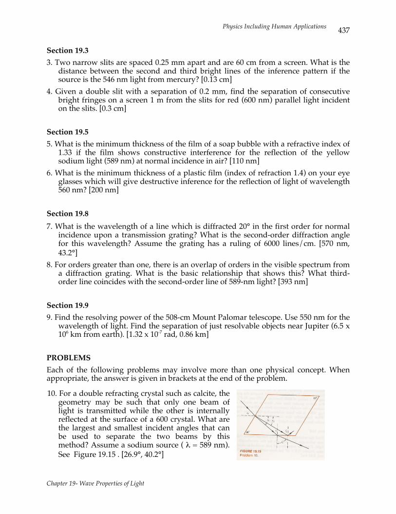
10. For a double refracting crystal such as calcite, the geometry may be such that only one beam of light is transmitted while the other is internally reflected at the surface of a 600 crystal. What are the largest and smallest incident angles that can be used to separate the two beams by this method? Assume a sodium source ( λ = 589 nm). See Figure 19.15 . [26.9°, 40.2°]
Physics Including Human Applications
Chapter 19- Wave Properties of Light
438
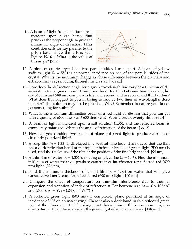
11. A beam of light from a sodium arc is incident upon a 60ø heavy flint prism at the proper angle to give the minimum angle of deviation. (This condition calls for ray parallel to the prism base inside the prism; see Figure 19.16 .) What is the value of this angle? [51.2°]
12. A piece of quartz crystal has two parallel sides 1 mm apart. A beam of yellow sodium light (λ = 589) is at normal incidence on one of the parallel sides of the crystal. What is the minimum change in phase difference between the ordinary and extraordinary rays in going through the crystal? [96 rad]
13. How does the diffraction angle for a given wavelength line vary as a function of slit separation for a given order? How does the diffraction between two wavelengths, say 546 nm and 589 nm, compare in first and second and in second and third orders? What does this suggest to you in trying to resolve two lines of wavelengths close together? This solution may not be practical. Why? Remember in nature you do not get something for nothing!
14. What is the maximum diffraction order of a red light of 656 nm that you can get with a grating of 6000 lines/cm? 600 lines/cm? [Second order, twenty-fifth order]
15. A beam of light is incident upon a salt solution (1.36), and the reflected beam is completely polarized. What is the angle of refraction of the beam? [36.3°]
16. How can you combine two beams of plane polarized light to produce a beam of circularly polarized light?
17. A soap film (n = 1.33) is displayed in a vertical wire loop. It is noticed that the film has a dark reflection band at the top just before it breaks. If green light (500 nm) is used, find the thickness of the film at the position of the first bright band. [94 nm]
18. A thin film of water (n = 1.33) is floating on glycerine (n = 1.47). Find the minimum thickness of water that will produce constructive interference for reflected red (600 nm) light. [226 nm]
19. Find the minimum thickness of an oil film (n = 1.50) on water that will give constructive interference for reflected red (600 nm) light. [100 nm]
20. Compare the effect of temperature on thin-film interference due to thermal expansion and variation of index of refraction n. For benzene Δn/ Δt = -6 x 10⁻⁴/°C and Δ(vol)/Δt = αV0 = (.24 x 10-3V0/°C)
21. A reflected green light (500 nm) is completely plane polarized at an angle of incidence of 53° on an insect wing. There is also a dark band in this reflected green light at the thinnest part of the wing. Find this minimum thickness, assuming it is due to destructive interference for the green light when viewed in air. [188 nm]

Physics Including Human Applications
Chapter 19- Wave Properties of Light
439
22. For objects that are not self illuminating the criterion for resolution is given in terms of the radius of the first dark fringe of the diffraction of a circular aperture. The diffraction fringe radius r is given by r = 0.61 λ/n sin i, where i is the angle subtended by the aperture at the object, λ is the wavelength and n is the index of refraction of the object space. Two objects are said to be resolved when the separation of images is equal to the diffraction fringe radius.
a. Find the percent improvement in resolving power of a microscope that is obtained by using an oil immersion lens system with n = 1.5.
b. Find the separation of just resolvable objects in green light (500 nm) if n sin i (called the numerical aperture) is one. [33 percent, 305 nm]
23. A standard sugar solution (1 g/cm3) is found to rotate the plane of polarization of light by 5.4° per cm of path length. A sugar sample of unknown concentration rotates the plane of polarization through 10.6° in a 5 cm long sample tube. Find the concentration of the sample. [0.4 g/cm3]
24. The Brewster angle for a specimen is 55° for 500-nm light. If the specimen is 0.001 mm thick, find the phase shift introduced by this specimen as compared with an equal thickness of water. [72°]
25. A thin wedge of air is formed between a sheet of glass 5 cm long and a horizontal glass plate. One end of the sheet of glass is in contact with a glass plate. The other end is supported by a thin metal film 0.05 mm thick. The horizontal plate is illuminated from above with light 589 nm. How many dark interference fringes are observed per cm in the reflected light? [17 fringes/cm]
26. Given a single slit of width D =kλ, where k = constant, find the angle of the first-order minimum for each of the following values of k: a. 1; b. 10; c. 100; d. 1000.
[a. 90° b. 5.7° c. 0.57° d. 0.0057°] 27. Given a diffraction grating with 5000 lines per cm, find the diffraction angles for
bluish-purple (400 nm) light in the first and second order. At which order does the 400 nm light overlap the reddish-orange light (600 nm)? [11.5°, 23.6°, third]
28. A helium-neon laser source produces a second-order spectrum for light of wavelength 632.8 nm at an angle of 30° using a certain diffraction grating.
a. Find the angle for the first-order sodium yellow (λ = 589 nm). b. Assume the grating is a reflection grating of 1-m focal length. Find the second-
order separation in the focal plane for the sodium doublet lines of λ equal to 589.0 and 589.6 mm. [a. 13.5° b. 0.7 mm]
29. The axes of a polarizer and an analyzer are oriented at 60° to each other. a. If polarized light of intensity I is incident on the analyzer system, find the
intensity of the transmitted light. b. If the incident light (intensity I )is plane polarized at an angle of 30° with respect
to the polarizer axis, find the intensity of the transmitted light. [a. 0.25 I ; b. 0.188 I ] 30. What is the minimum thickness of a water film on glass that will give destructive
interference for 546-nm light by reflection from surfaces of the film? [102.4 nm]